5. 3D Printing and Scanning#
Group A (Thursday Session)#
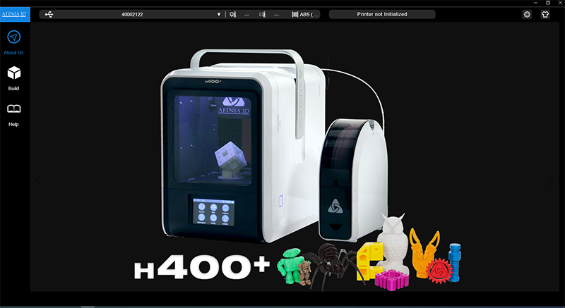
Test the design rules of Afinia H400#
FabLab Kamakura has some of Afinia H400 printers.
In order to detect the design rules of it, we, three members of Thursday session, each printed the same model in the different combinations of the printing parameters, materials and also another 3D model.
The test result is as follows.
Test plan
| test A | test B | test C | test D | test E | test F | |
|---|---|---|---|---|---|---|
| High Quality | Yes | |||||
| Middle Quality | Yes | Yes | Yes | Yes | ||
| Low Quality | Yes | |||||
| setting : LayerThickness | 0.35 | 0.25 | 0.15 | 0.25 | 0.25 | 0.25 |
| setting : Infill | 0% | 65% | 99% | 65% | 65% | 65% |
| setting : Quality | Fast | Normal | Fine | Normal | Normal | Normal |
| setting : Support | None | None | None | None | None | Yes |
| setting : Raft | Yes | Yes | Yes | Yes | Yes | Yes |
| setting : Unsolid Model | Yes | Yes | Yes | Yes | Yes | Yes |
| Material : ABS | Yes | Yes | Yes | |||
| Material : PLA | Yes | |||||
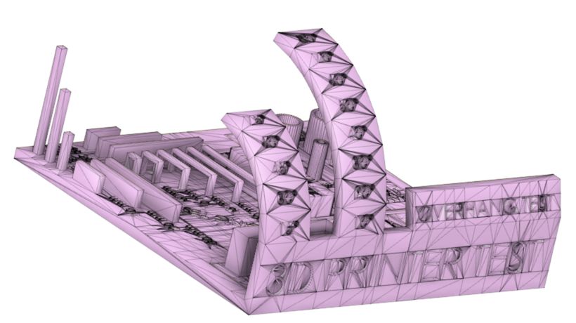
| Model : All In One 3D Printer test | Yes | Yes | Yes | Yes | ||
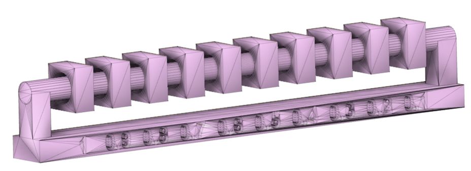
| Model : clearance test | Yes | Yes |
| All In One 3D Printer test *1) | clearance test *2) |
|---|---|
 |
 |
*1) thingiverse site
*2) fab academy ( design rules, supports, clearance, stl )
Results of “test B” and “test D” ( Oka )#
I printed All In One 3D Printer test model with the parameter below twice.
One was for ABS and the other was for PLA for comparison the outcome between two different materials.
1 2 3 | |
test B (ABS)#
it seemed that the good shape was printed as the outcome except overhang testing. If the angle gets larger than 60 degree at overhang test, it would be entangled. the bridge test got similar outcome to overhang test because they did almost same thing between the bridge test and the overhang test at 90 degree.
test B (PLA)#
the surface of it was shinier than the one printed by ABS. the things successfuly printed were not so different from the one printed by ABS. but it seemed that the outcome got more entangled at overhang testing than ABS. I guessed it was because the PLA started fixing faster than ABS.
Results of “test C” (Tsuchiyama)#
Output Test Sample of Afinia H400#
Since FabLab Kamakura has multiple Afinia H400s, I had decided to test samples of low, medium and high quality to verify the accuracy differences.
(1) Download Test Samples#
I downloaded test data from Thingiberse in order to check design rule on the Afinia H400.
(2) Reading date#
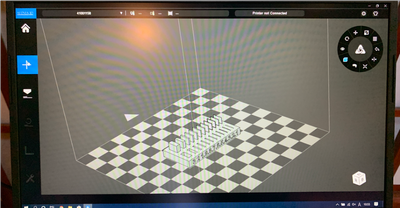
Open the software for the Afinia H400.
Open “Build” and load 3D files from “+”.

↓
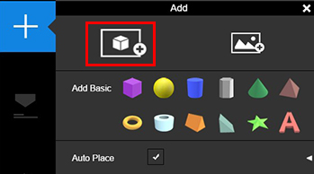
Select “3D_Printer_test_fixed_stl_3rd_gen.STL” to open the file.
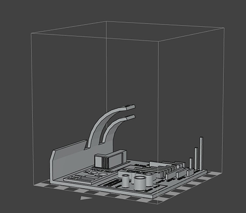
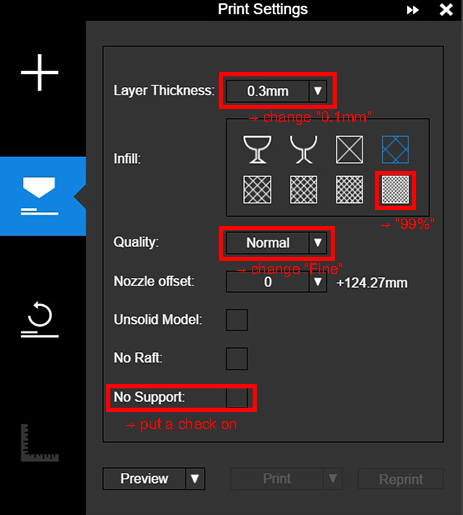
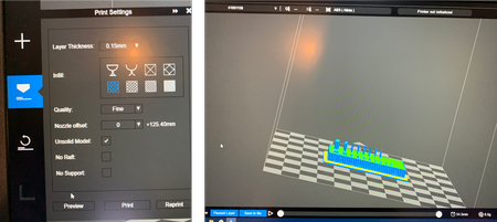
An output accuracy is set from the “nozzle” icons. This time - Layer Thickness : 0.1mm - Infill : 99% - Quality : Fine - No Support
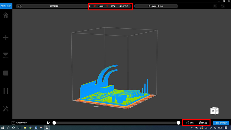
Click “Preview” to display the time until actually outputting and the amount of filaments consumed.
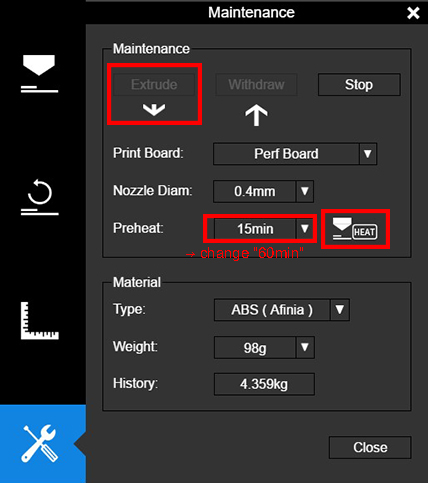
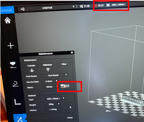
Further, it is preferable to set the temperature of the table to 50℃ or higher when using the filament of the ABS.
The reason for this is that ABS is easy to shave, so if this temperature setting is not performed, the probability of failure is increased.
The temperature of the table can be set from the “panner and driver” icons.
Set the Preheat time to “60min” and click “HEAT”, and wait for 30 minutes to one hour before the table gets warm enough.
Press the print button to display the detailed time required for printing and start printing.

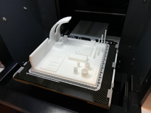
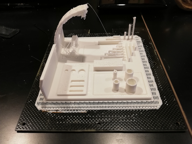
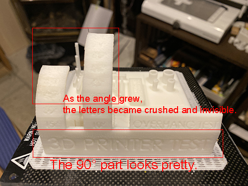
(3) Result#
About nine hours later, it succeeded in outputting the test sample.
By setting the infill to 99%, it is a fairly robust model.
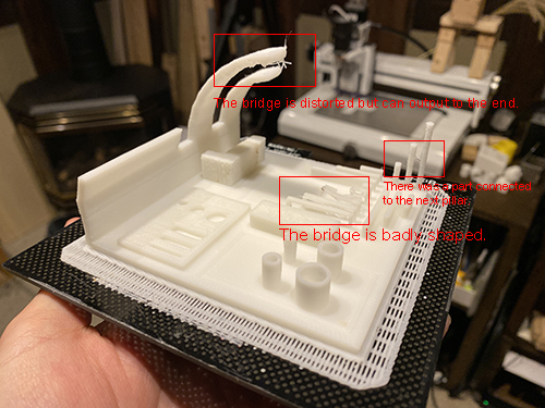
The bridge is distorted but has output to the end.
The shape of the arch is almost printed out.
However, the letters indicating the angle of the arch to the letters on the vertical wall were crushed and invisible.
(4) Evaluate#
I tried the high quality output this time, but I couldn’t output it well for the time being.
However, the strength of the model was so strong that it was difficult to remove it from the table.
Quality settings are not recommended.
Results of “test A”, “test E” and “test F” ( Oguri )#
I tried “test A”, “test E” and “test F” in the above table.
test A#
This is a ” fast but low quality ” trial.
LayerThickness was set to be 0.35mm which the largest number in the printer driver,
Infill was set to be 0%, which might lead a problem.
And, the quality was set to be “Fast”, although the actual meaning of this was not sure.
| printing parameter setting | print preview ( estimated time is 2 hours ) |
|---|---|
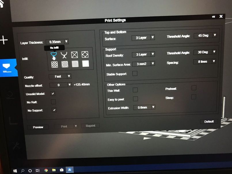 |
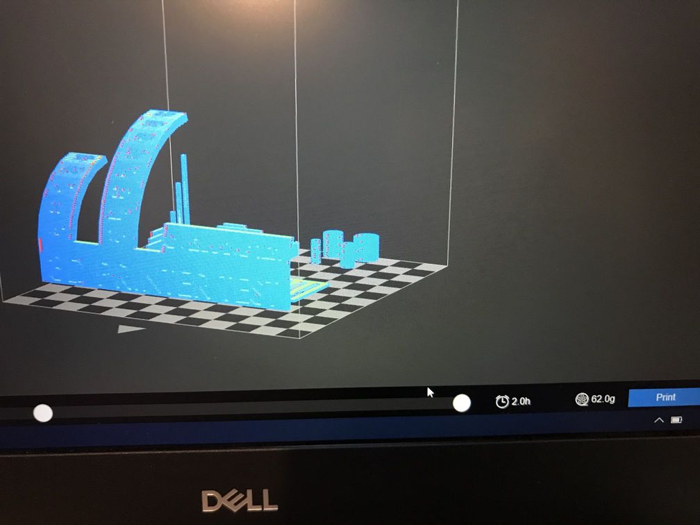 |
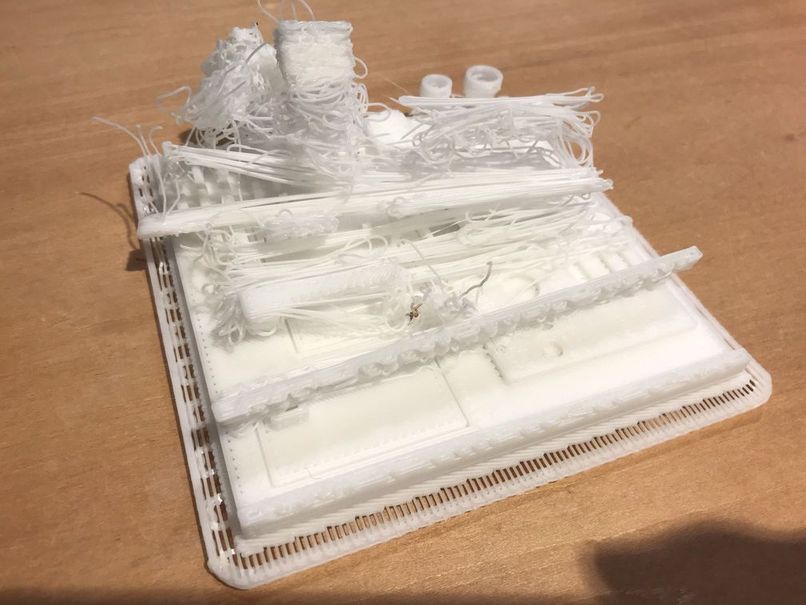
The most portion of this model was not printed properly.
test E#
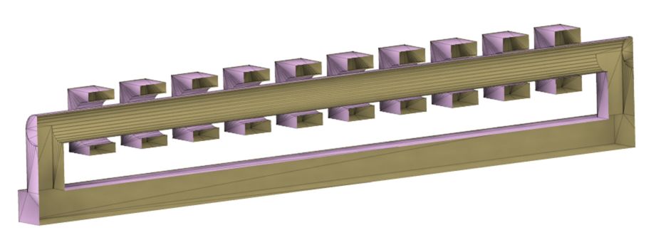
This model has the shaft & hole (square washers) structure, which is preferable to check printing performance for the clearance between two or more items.
Printing parameters were set to be the same as the “Middle Quality (test B)”, therefore, no support.
The result was no good, because the square washers were moving with the printer head before the shaft part was printed. So, I stopped the printing process.
| section of the model | |
|---|---|
 |
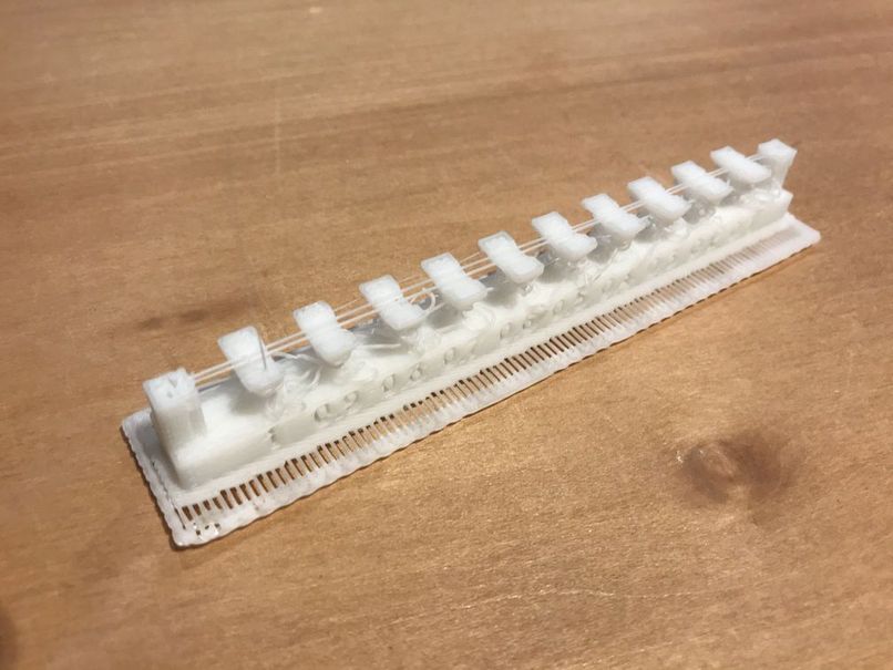 |
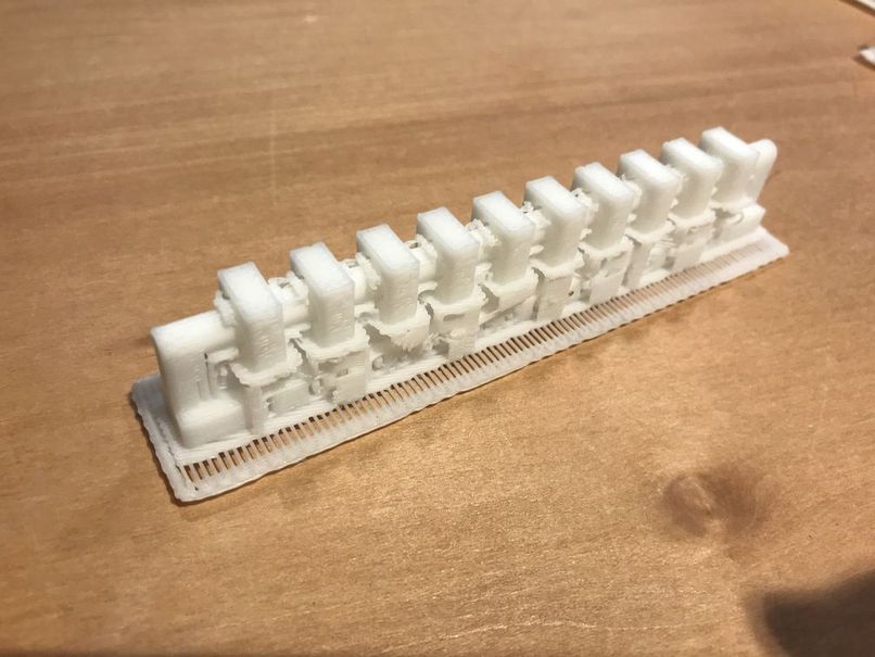
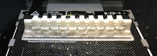
test F#
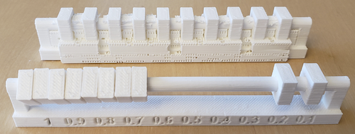
The support was added, the result was fine.
As shown in the right photo, all square washer except the right end (0.1mm clearance) could move.
So, with this printing parameters, 0.2 mm or larger clearance is enough to activate the shaft & hole structure.
| before removing the support | after finishing |
|---|---|
 |
 |
Group B (Saturday Session)#
Yume#
I tested the design rules for Afinia H400+.
Since I wanted to make a ball shaped structure with skeletons, I used existing design data to test dimensions and wall thickness, and designed data of a structure to test how thin can it go to build a 90 degrees bend.
Testing wall thickness#
I started with wall thickness. The stl data is downloaded from here.
After connecting the printer to the laptop, I opened AFINIA 3D software, and opened the stl data.
I set the layer thickness as 0.15mm, and selected the filling rate as the image below. And it showed the preview and the printing time (54 minutes).
Before starting the printing, I preheated the printing bed. For other printers, when you start printing, it usually heats up the bed, then the nozzle to 270 degrees C, then start printing. However, for AFINIA H400+, it starts printing once it heats up the nozzle without much attention to the bed. If the bed is not heated enough, it might cause the printed item to bend especially when it has bigger bottom area.
After pressing the pre-heat button and set the time to 60min, you can obeserve the bed temperature raising on the top of the interface.
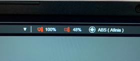
I started printing once it reached approximately 50 degrees C.
Once started, the temperature’s unit turns to percentage. 100% is 100 degree C so 48% represents 48 degrees C.
This is how it is printed:
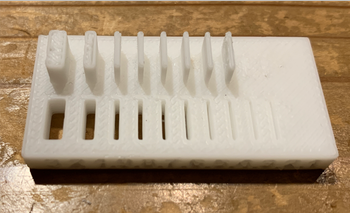
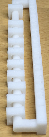
As seen in the printed item, this printer with this setting can print slit down to 0.5mm (0.3 & 0.4 still recognisable, but not cut through), and a wall down to 0.5mm.
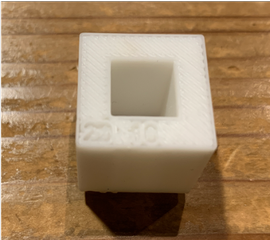
Testing dimensions#
I also printed the dimentions calibration structure. The stl file is here.
I set up the 3D printer as before, and printed the structure.
It turned out to be like this:
I used a caliper to measure the inside and outside of the structure.
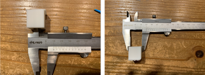
The inside was 9.9mm while the outside was 19.95mm. They were set to be 10mm and 20mm so the difference is the error of this printer.
Testing overhang#
This test is to see down to what thickness can the printer handle an 90 dgrees arc. s
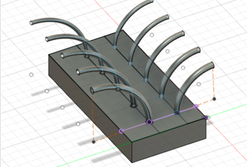
Creating 3D data#
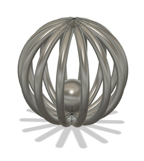
I created 3D data for a structure to test overhang of different thickness.
I firstly drew the base and the arcs’ basis with a range of diameters from 3.3 to 2.1mm with 0.3mm difference each. There were 2 rows because one is for an arc with radius of 20mm and the other of 30mm.
Then I drew arcs from the center of each circle. There radius of arc are 20mm and 30mm of different rows.
I used “sweep” feature from “create”.
Type > Single Path
Profile > the circle on the base
Path > the arc
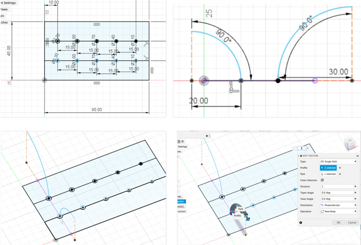
After extruding the basis, the model is built!
I used the same settings for the printer and it’s printed like this:
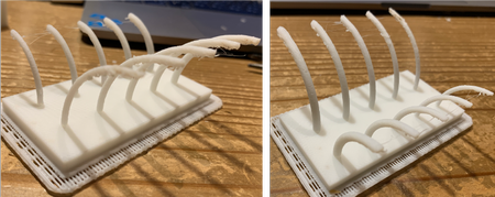
From the picture on the left, it can be seen that all of those made into arc with 30mm radius has some unstable structure, while the 20mm arcs on the right showed better performance - 3.3mm seems stable, 3.0mm rather stable, but some unstable structure for diameters under 2.7mm.
The file I created to test overhang is linked in my individual page.
clearance(Kimura)#
I selected “clearance” from the sample test file and printed it.
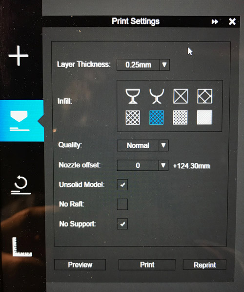
- Configuration
- Layer Thickness –> 0.25mm
- Infill –> Roughest
- Quality –> Fast
- Nozzle offset –> 0
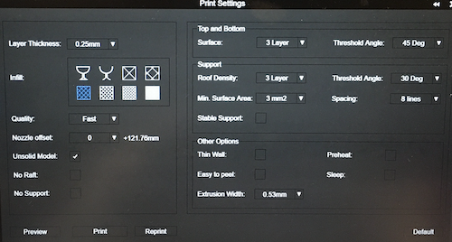
-
Materials used –> ABS resin
-
Test started
I think it took 37 minutes to print.
I was able to print well.
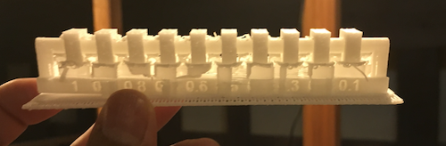
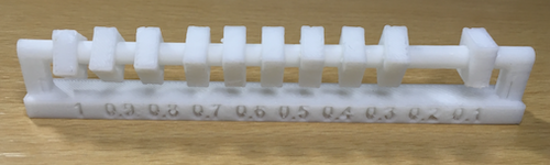
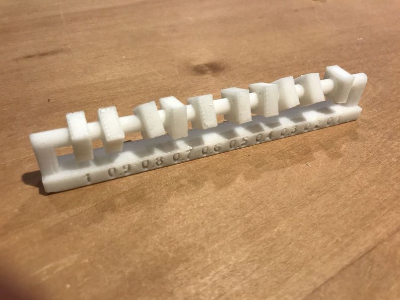
- Evaluation of clearance results
Everything was rotatable except for the 0,1 mm clearance.
The 0,2 mm clearance (second from right) is a bit caught.
Depending on the accuracy of the parts used, I thought the 0,3 mm setting (third from right) was the best.
Angle (Yanome)#
I wanted to make the below object, but I’m not sure that I can make it without support. So I downloaded “Angle” sample from here and checked until how much angles the support is needed.
The process of printing things using 3D printer is written in my week05 page.
Build the model into the workspace.
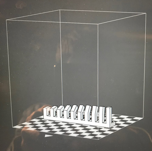
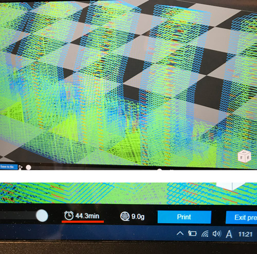
I set the printing condition with Layer Thickness = 0.25 mm, Infill = 60 %, Raft, No Support.
Printing time was calculated as 44.3 min as I previewed at the above printing condition (Note that the size of your object also affects the printing time.)
Print!!
Finished~
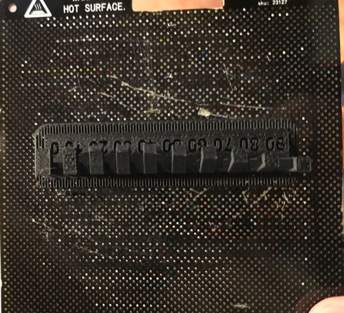
Assess the angles!!
At all the angles (0 - 90°), the arms could be printed. My Expectation is that the arm fall down or bend at a certain angle. So the instructor told me the if the size of the parts in vertical is small, it can be printing vertically. It’s based on th e experience.
But the point is that the bottom of the arm parts collapses with increasing the angle (60° - 90°).
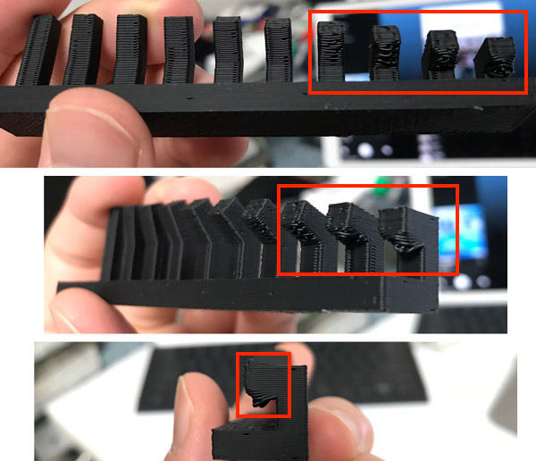
It also affected the design of my ring object…
So I need to consider this breakdown of the bottom in the case of printing without support.
Additinal tips
In the Asia review, Rico and who are the instructors in Kamakura, told me I should do Bridge Test for the sphere shapes like my object.
And then Jun Kawahara shared me the really great tips article about how to make the bridge without support.
Thank you all for teaching me!
I’ll apply those tips to the next time!!
Tips for making bridge without support
- Increasing Cooling
- Decrease Flow Rate
- Decrease Temperature
- Decrease Print Speed
- Adjust Model Orientation