Electronics Production
In this week's assignment we had:
Group assignment:
Characterize the design rules for your PCB production process
Individual assignment:
Make an in-circuit programmer by milling and stuffing the PCB,
test it, then optionally try other PCB processes
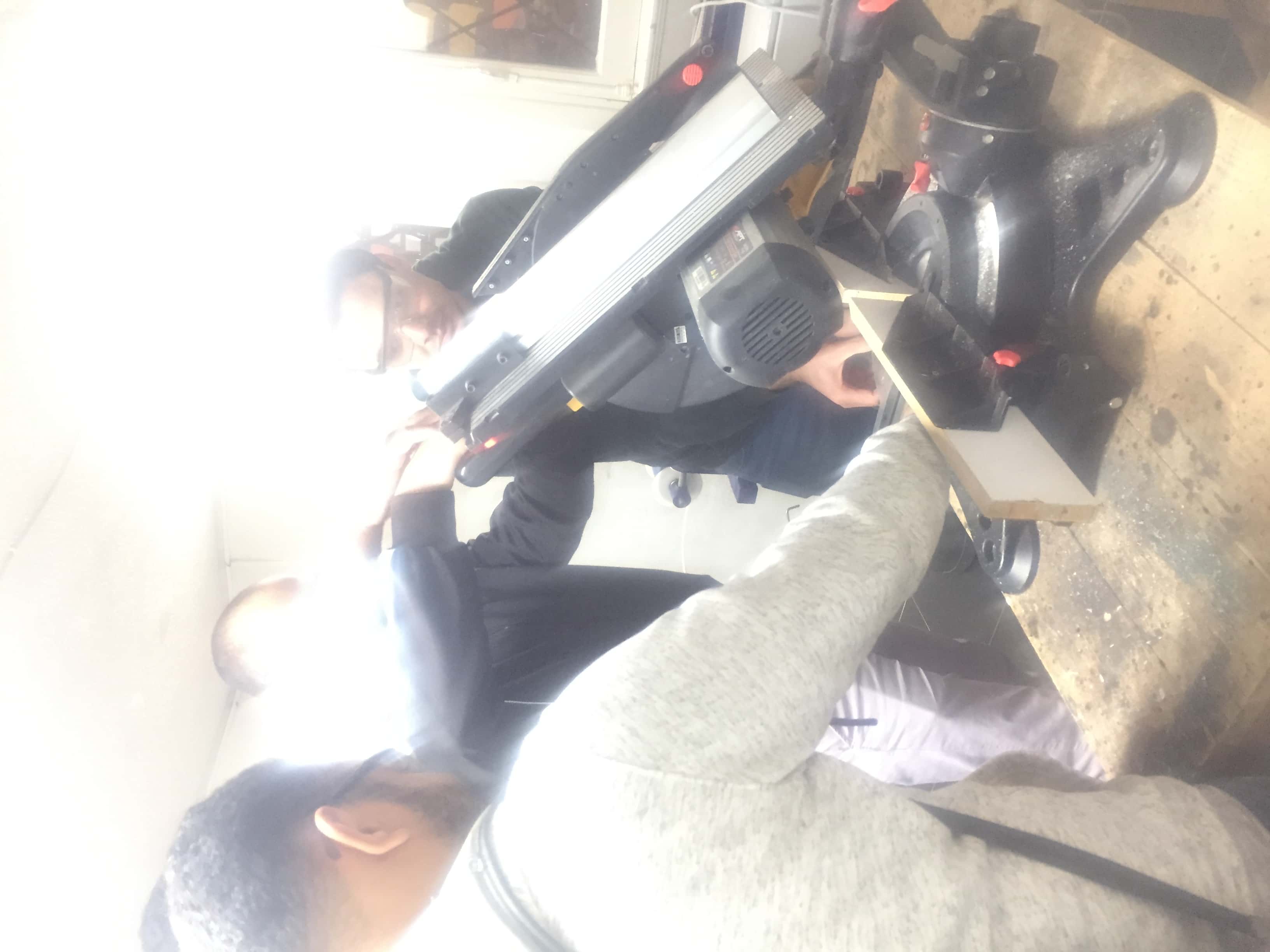
For the group assignment
Our great mentor
Mohamed Kamel introduced to us the PCB milling process and how to use the machine and the software.We did a test on the milling machine to check the precision of the machine and tools.Here are the steps:
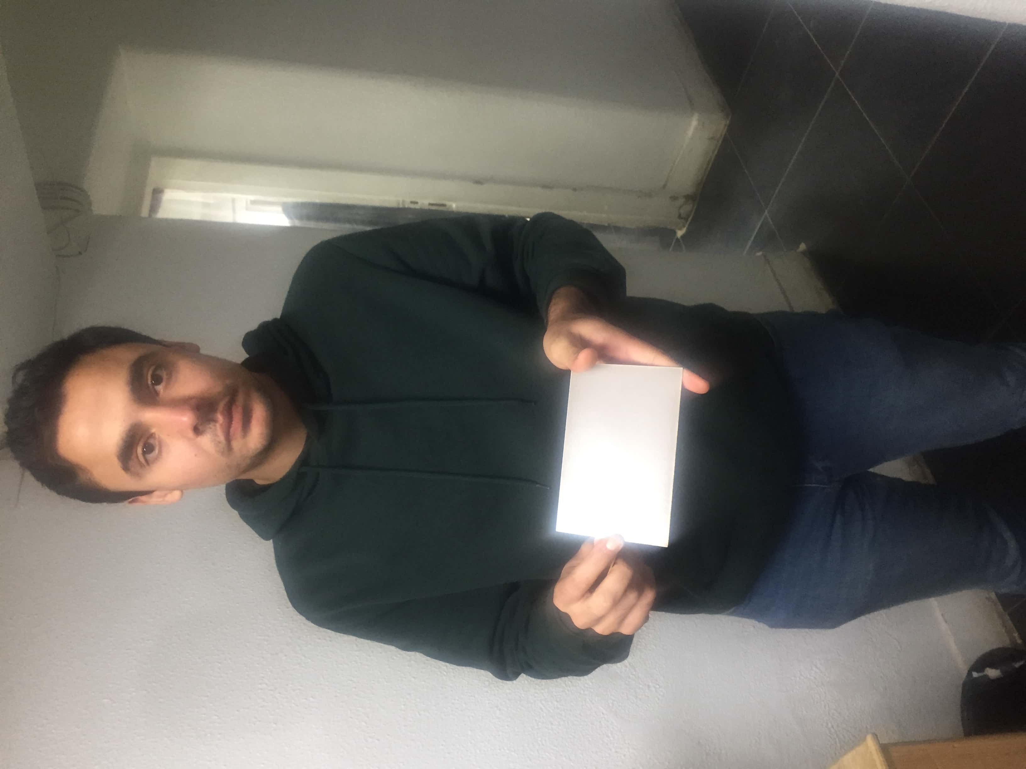
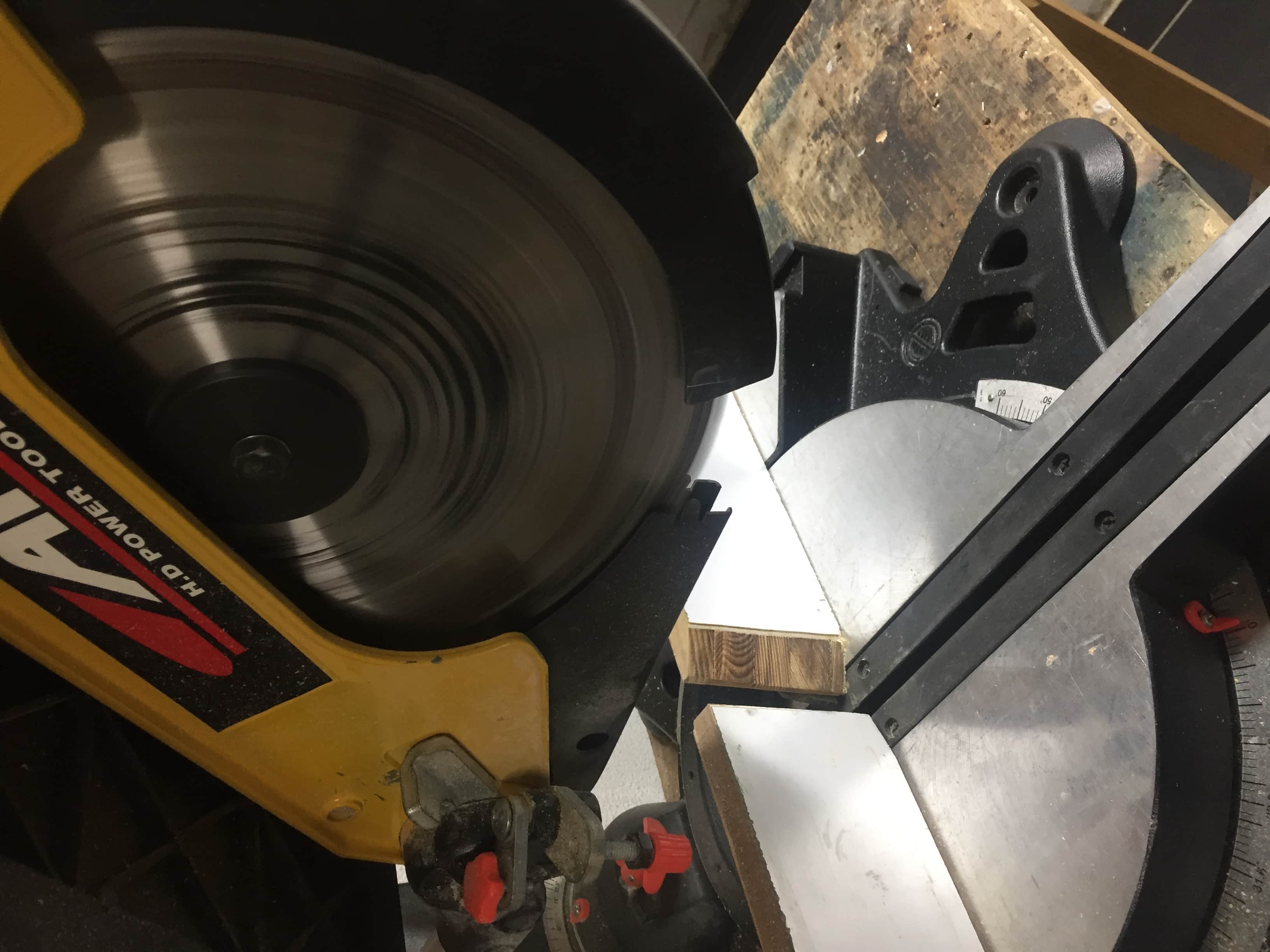
1)We took an FR1 and cut it to the desired dimensions.
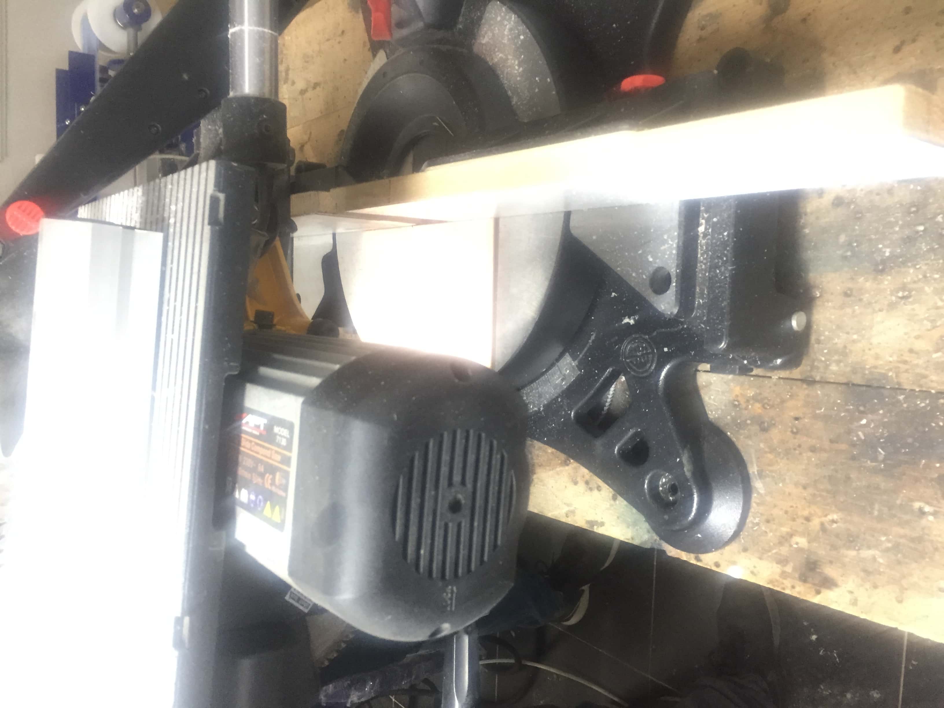

2)We used a double face tape and pin tape to hold the board on the machine.


3) Our mentor
Mohamed Kamel
configured the settings of the software (it will be explained in details in the individual assignment as it is the same process).
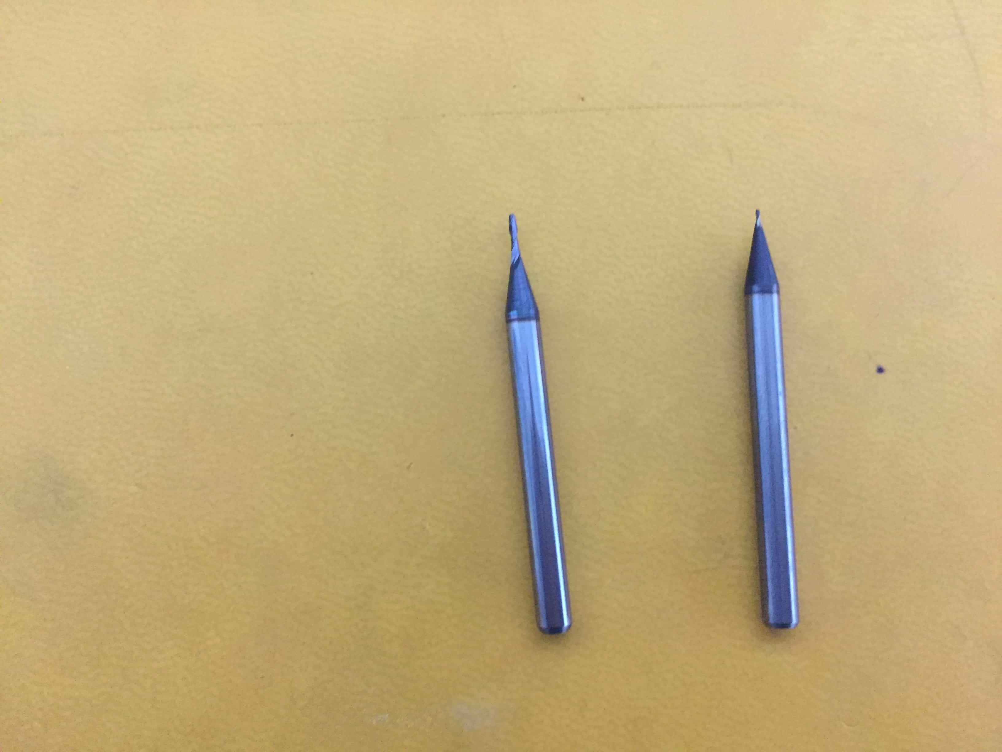
4) He installed the tool for traces 1/64.
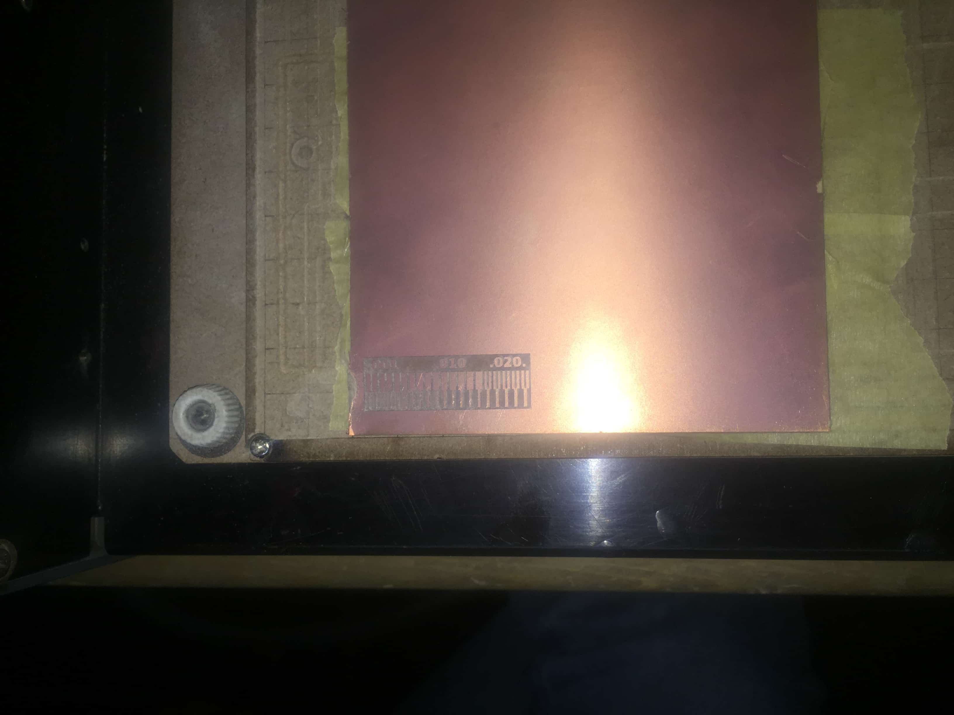
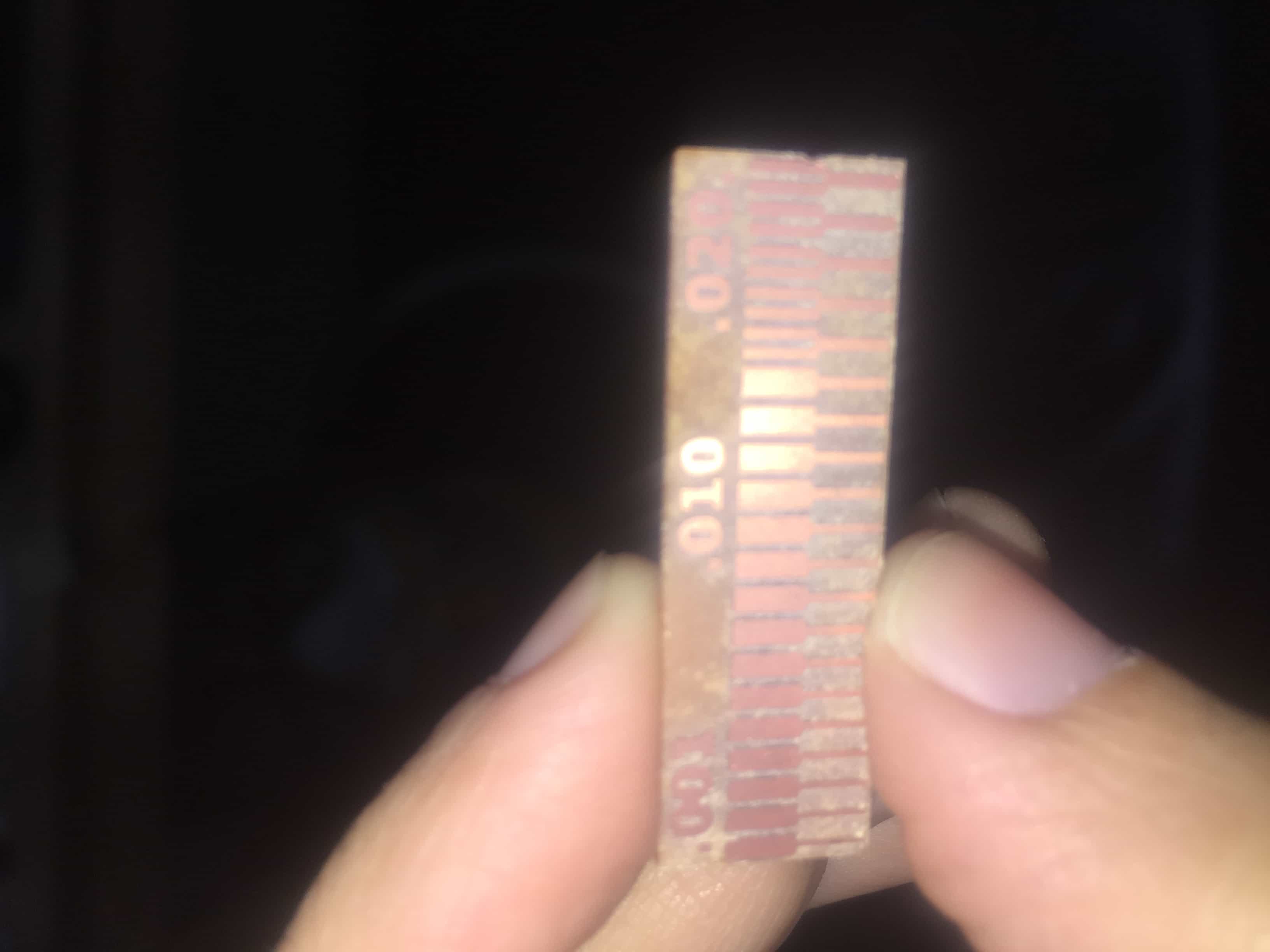
5)We tried to make the traces test board as advised in the lecture to check the precision of the tool.

6)Then he changed the tool to cut the board 1/32.

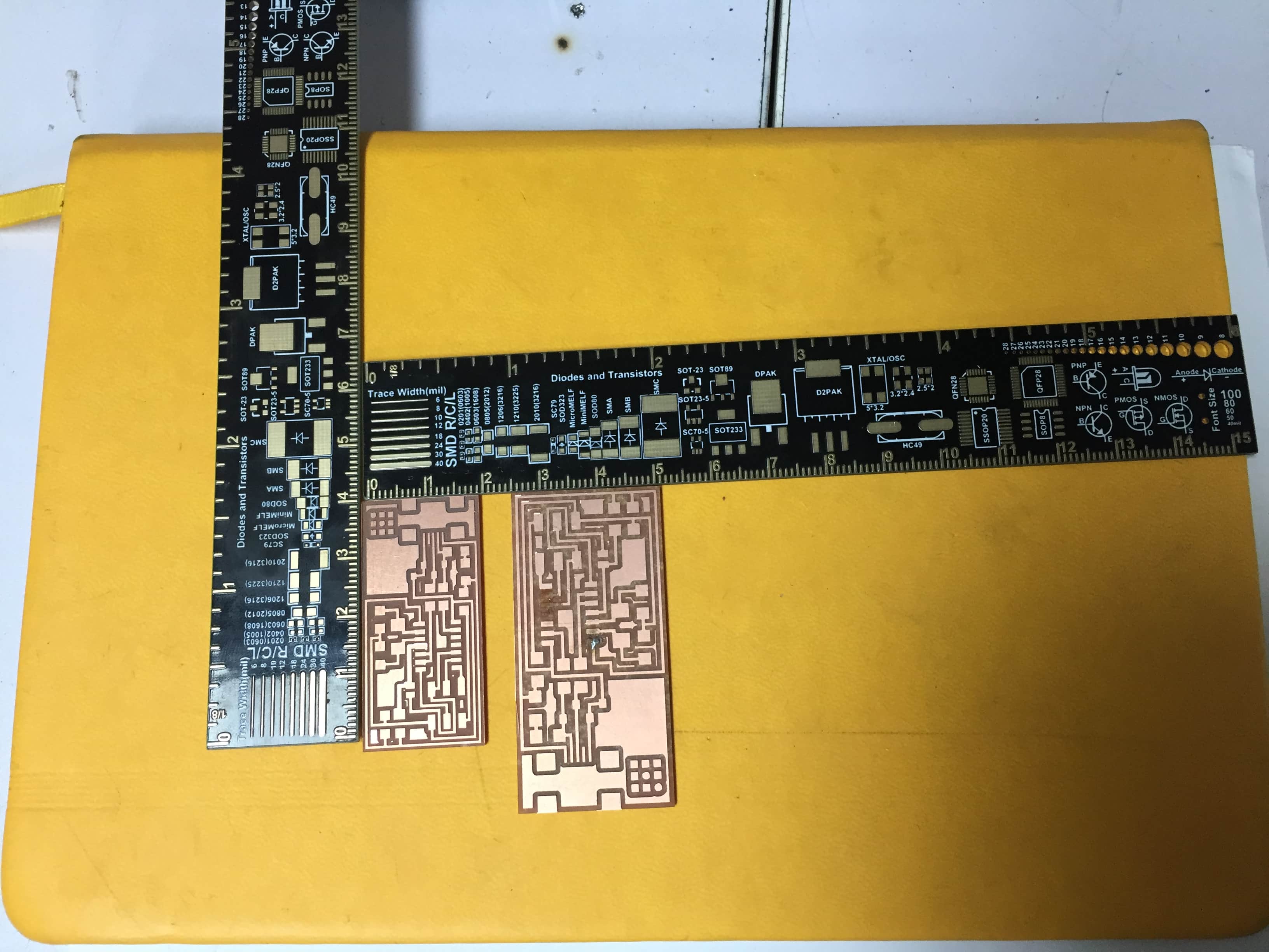
Here is the test board finished:
Used tools:
7) Then he repeated the process to make another example board to show us soldering techniques.
We are supposed to solder from the middle out ,and the short and small components first:

For the individual assignment:
So this week's assignment is doing the brain of the system,I'm making an in Circuit programmer to program other circuits.
I would like to thank
Ahmed Ibrahim
,
Ahmed Saeed and Amani Ayman for helping me out.
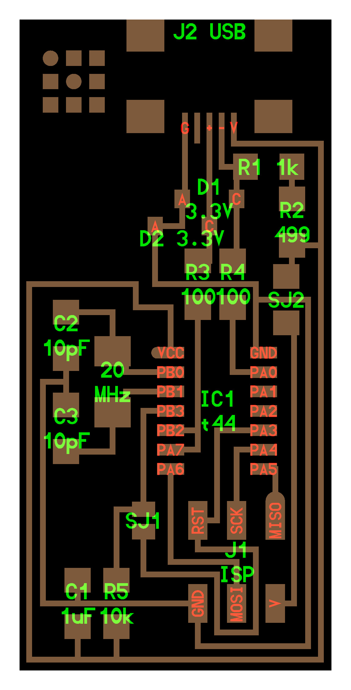
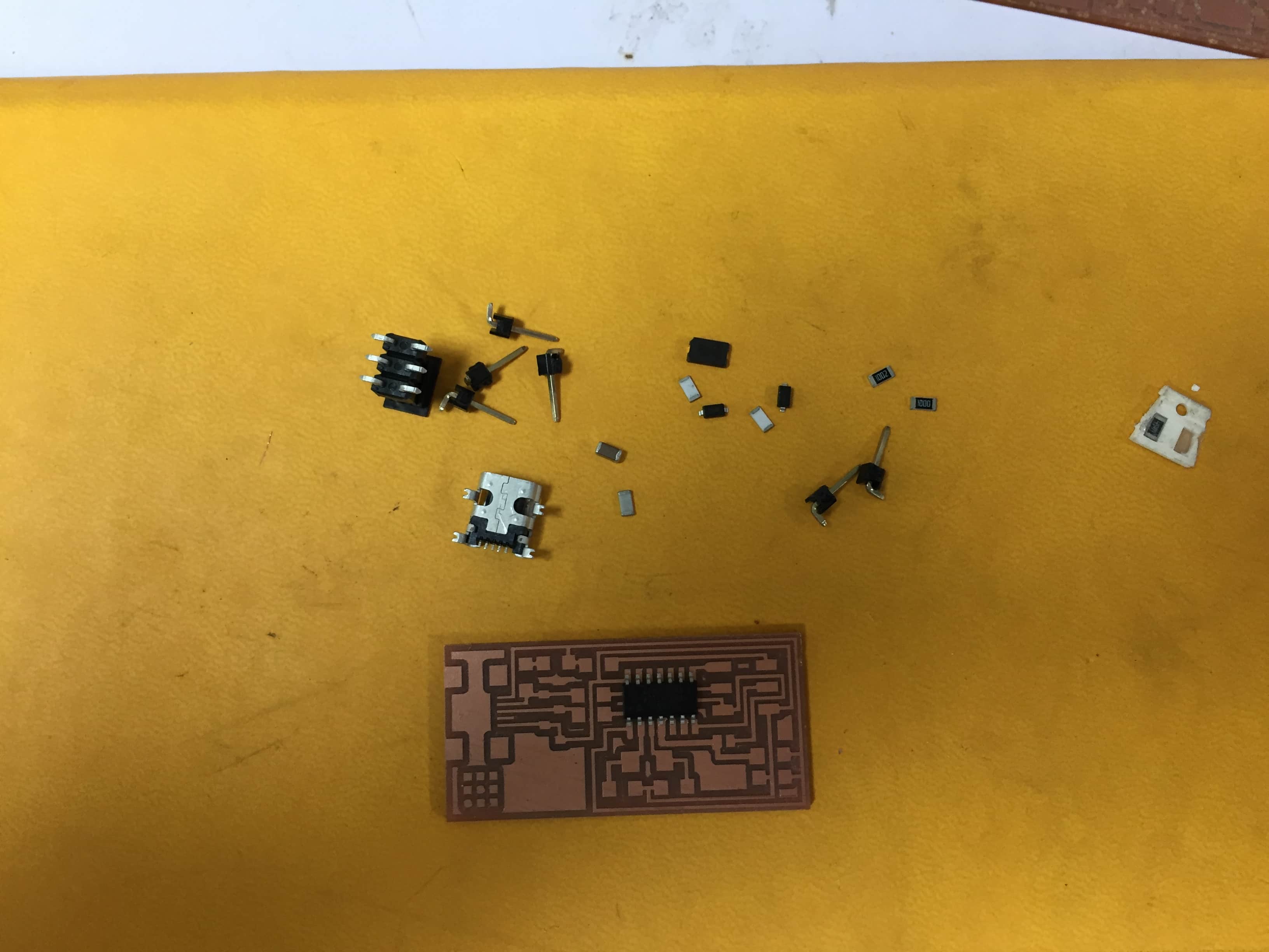
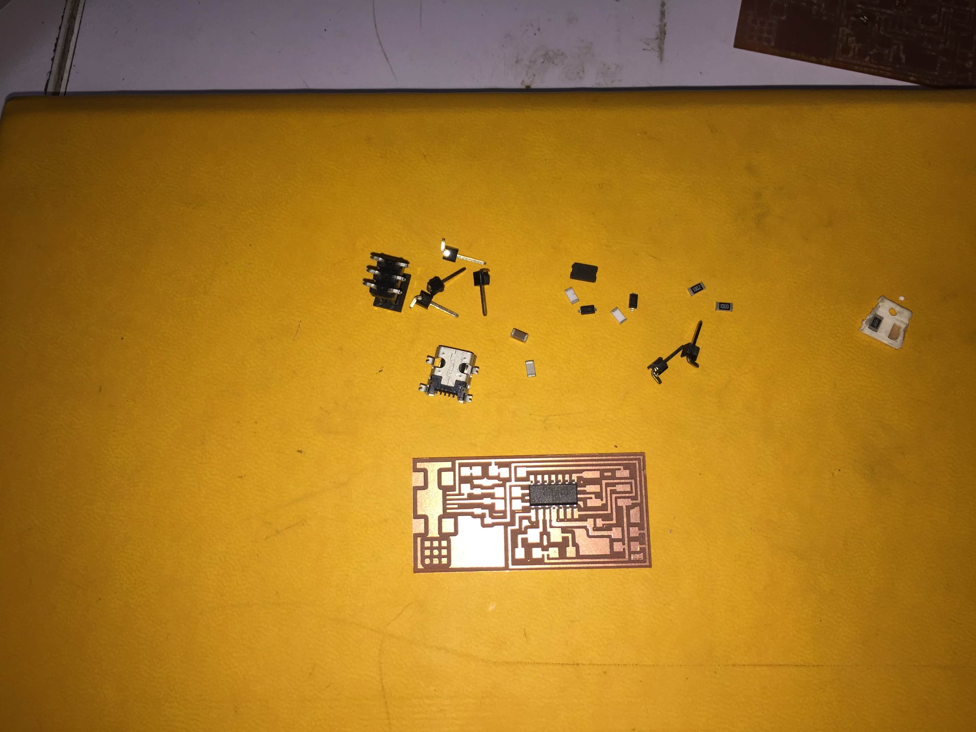
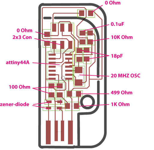
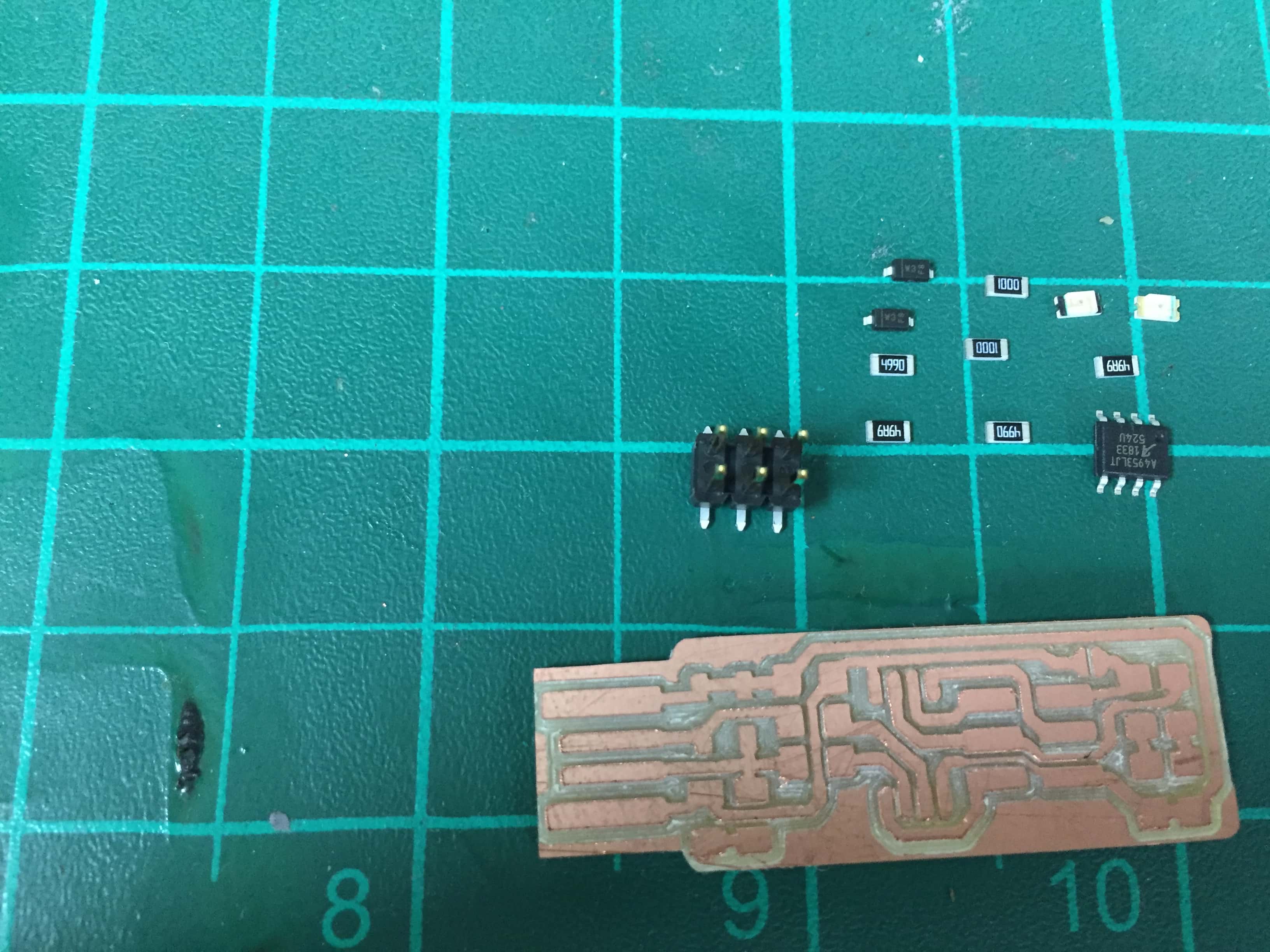
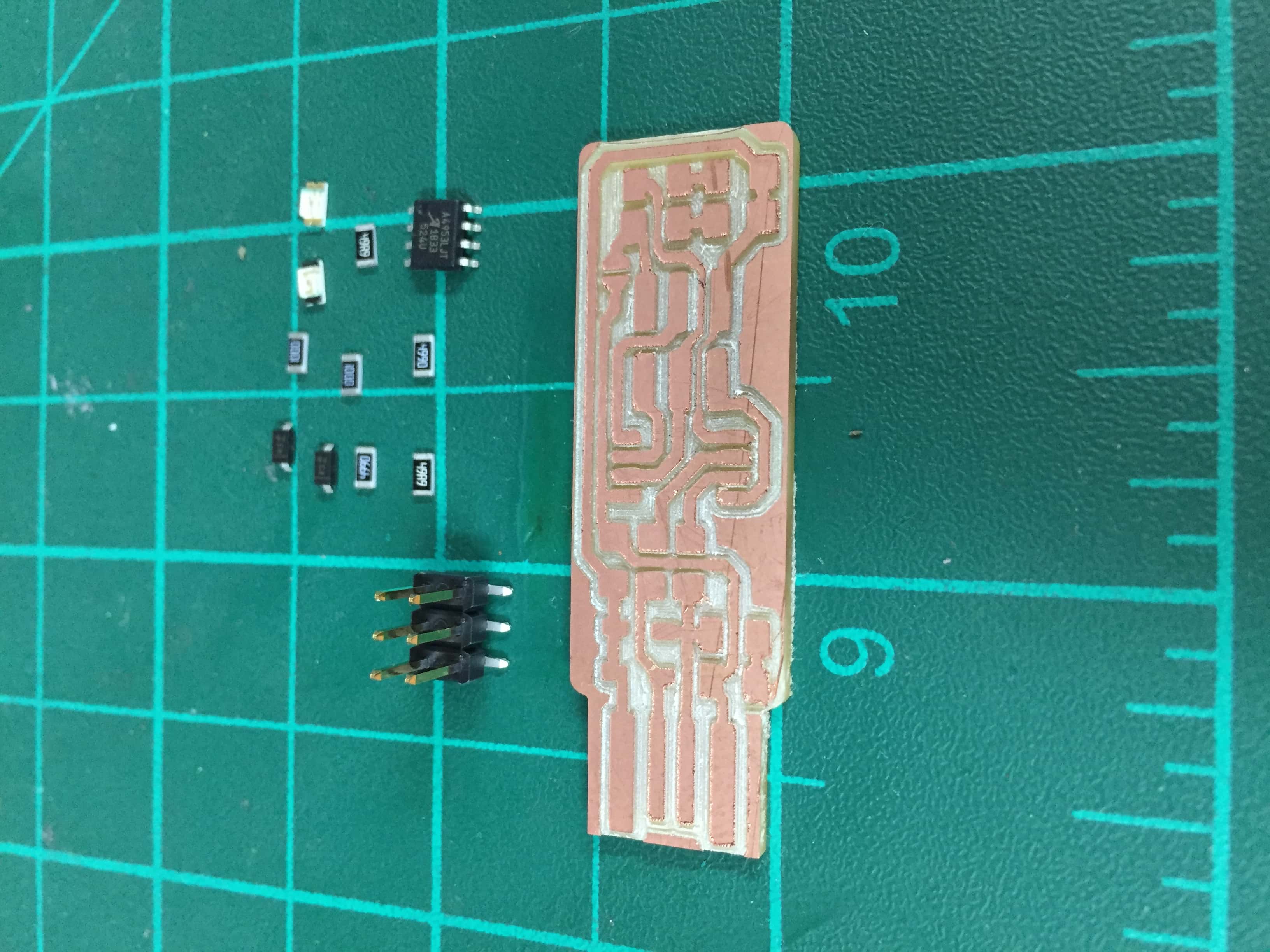
I chose to do an ISP44,here are the components:
ISP44 components :
-1 capacitor 1 uf
-2 capacitors 10 pf
-1 Low-frequency Crystal Oscillator 20 MHZ
-2 diodes 3.3 V
-1 resistor 10 Kohm
-1 resistor 1 Kohm
-1 resistor 499 ohm
-2 resistors 100 ohm
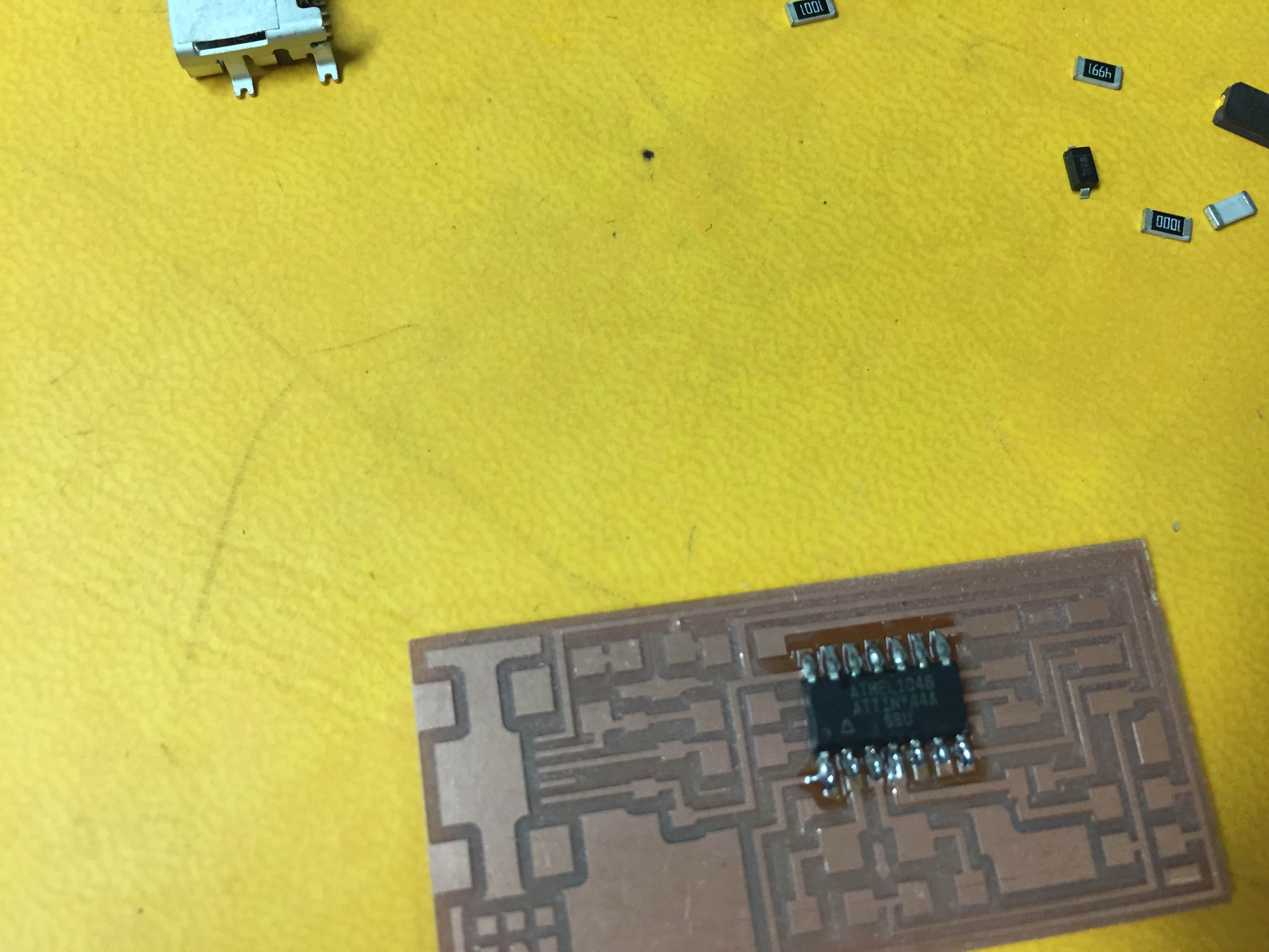
-ATtiny 44
-J2 USB
-J1 ISP
-SJ1
Here is a brief explaination on the components
Inside the microcontroller ATtiny 44 there is internal clock ,as written in the datasheet ,but as you see in the circuit we can find
crystal oscillator ,
we can always use external clock to be compatible with the given application or the other connected circuits.
There are resistors that are used as pull up or pull down, also we can use resistors
for safety to make sure the voltage wouldn't burn the connected pin or components.
In addition ,there are bypass capacitors.
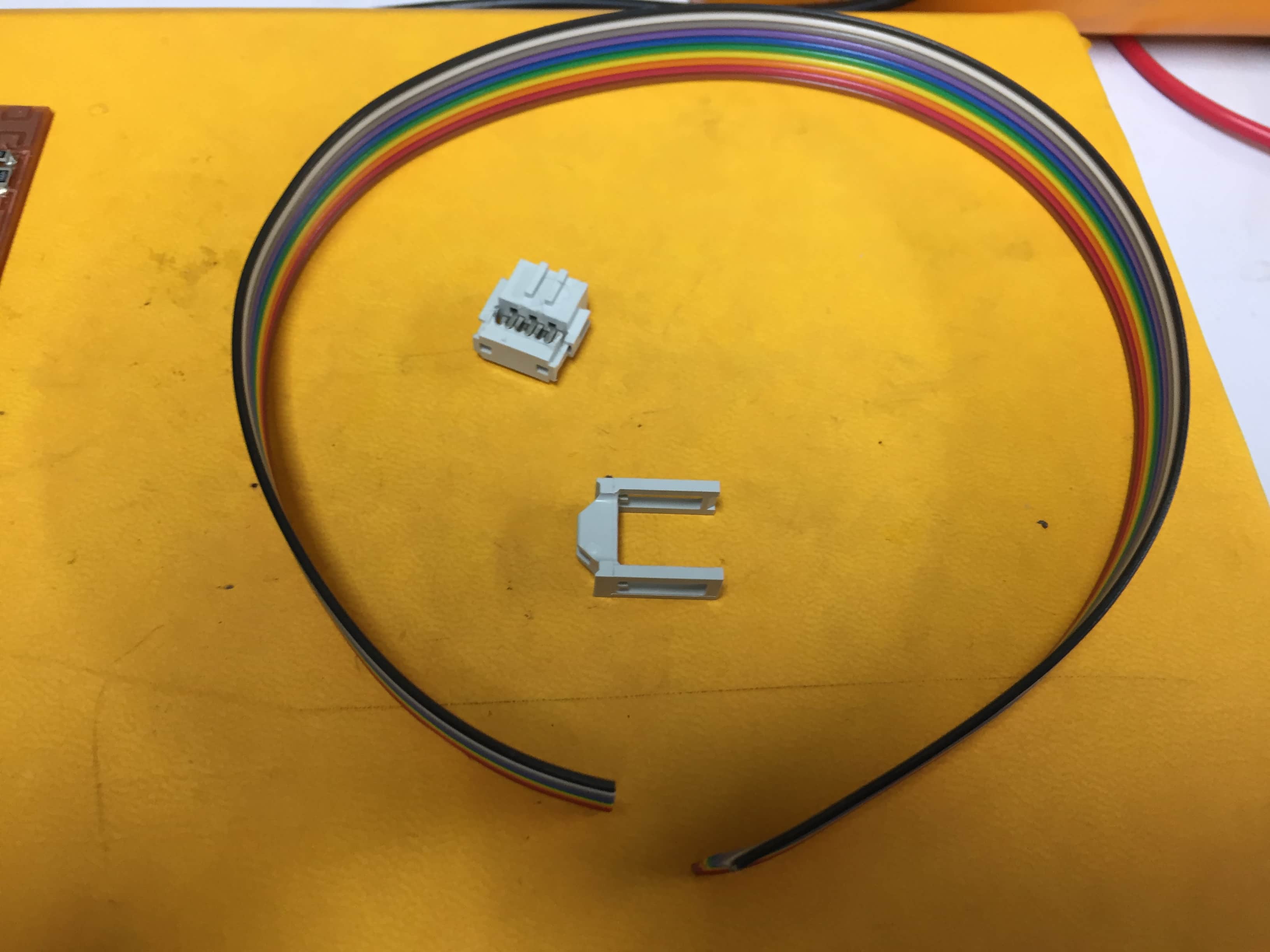
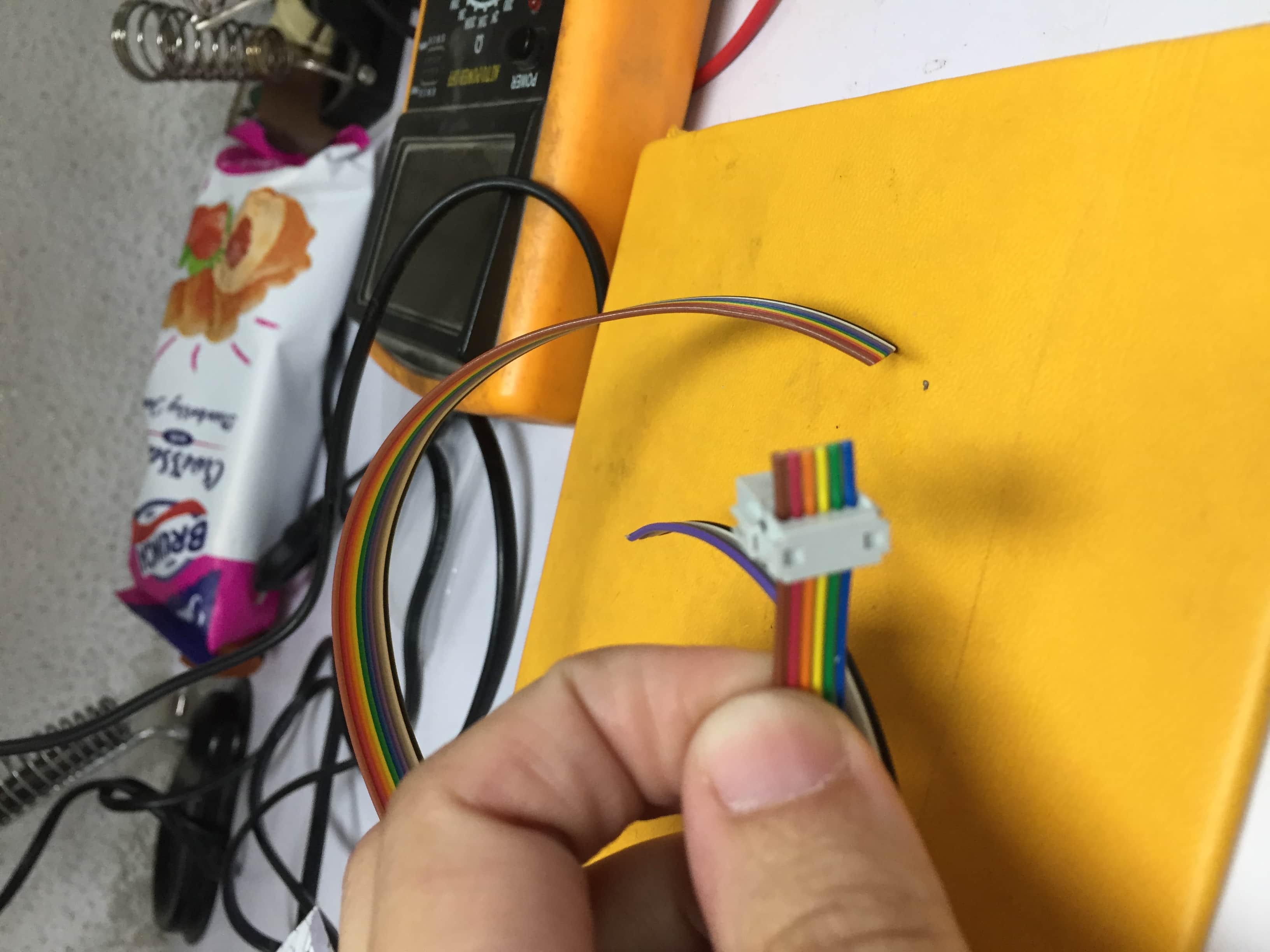
There are the ISP pins for communicating with other circuits.
For ATtiny 44 I searched about it to figure it out.
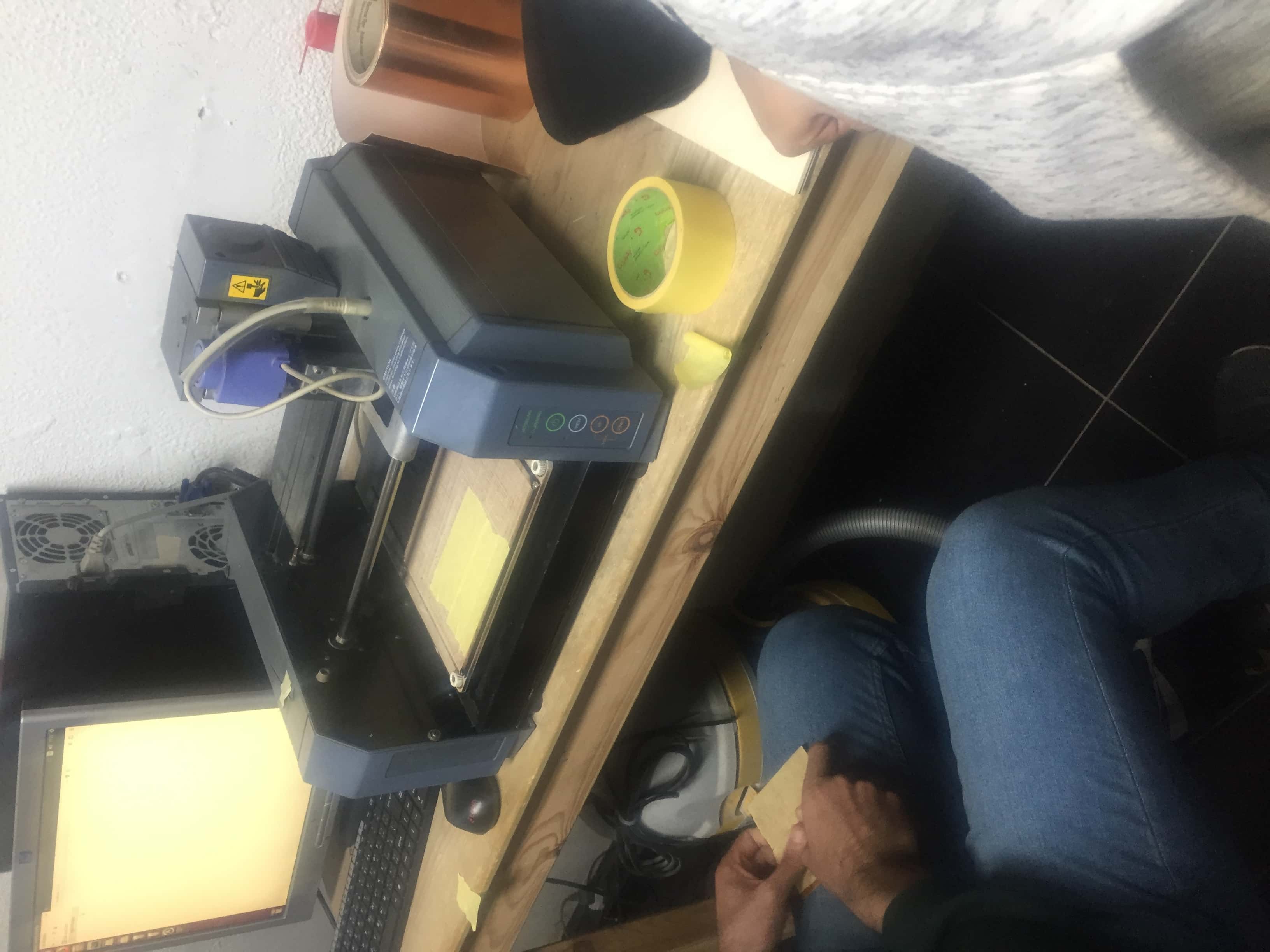
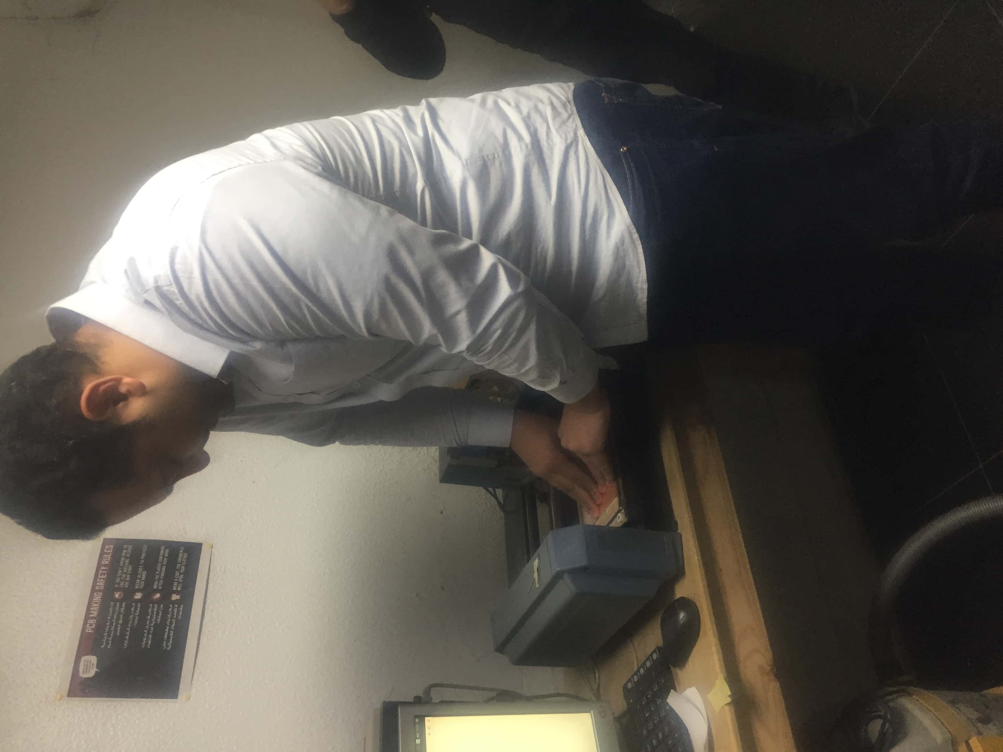
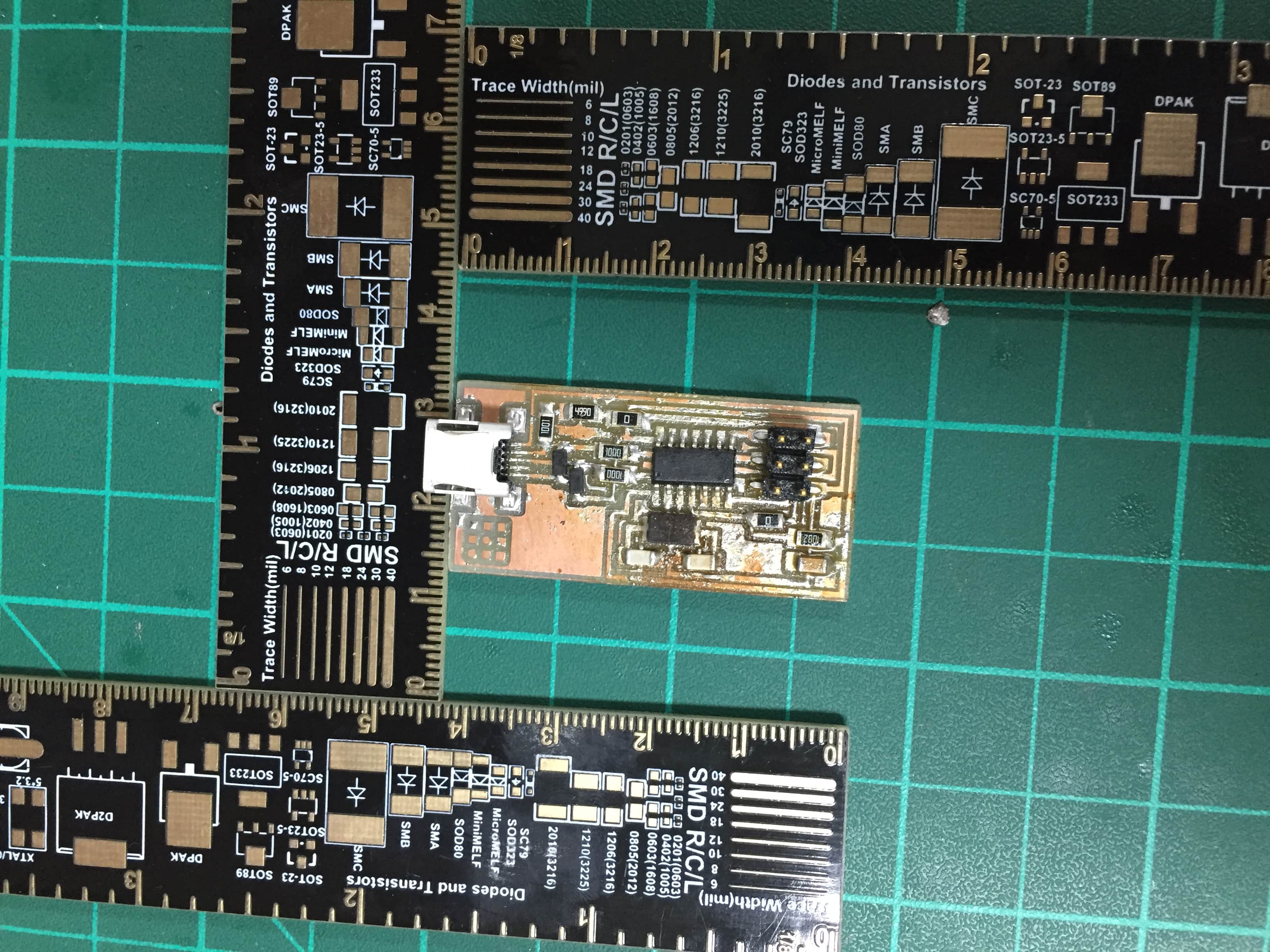
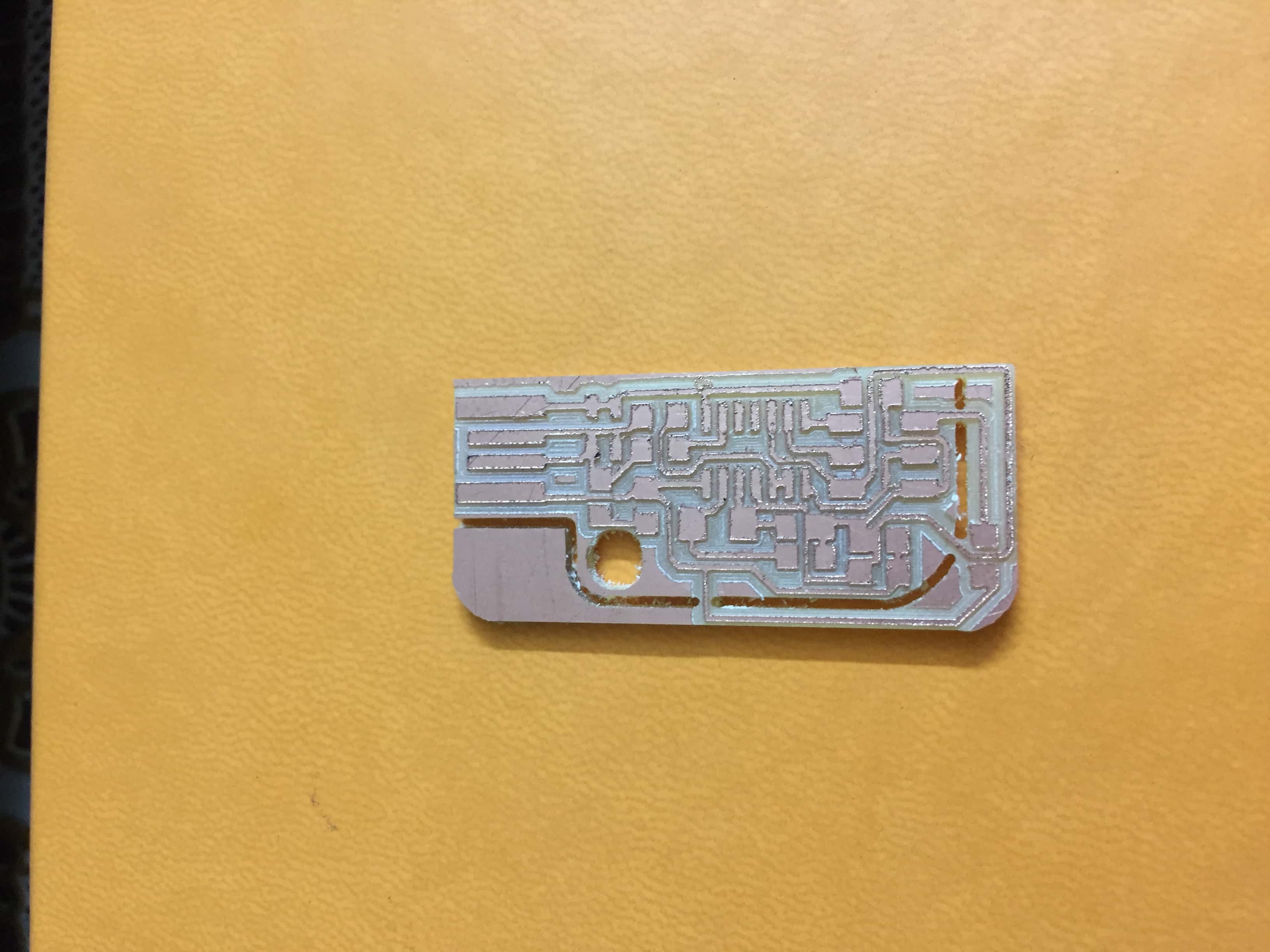
The process used to do this PCB is mainly milling on Rolland Modela MDX-20 Milling Machine.
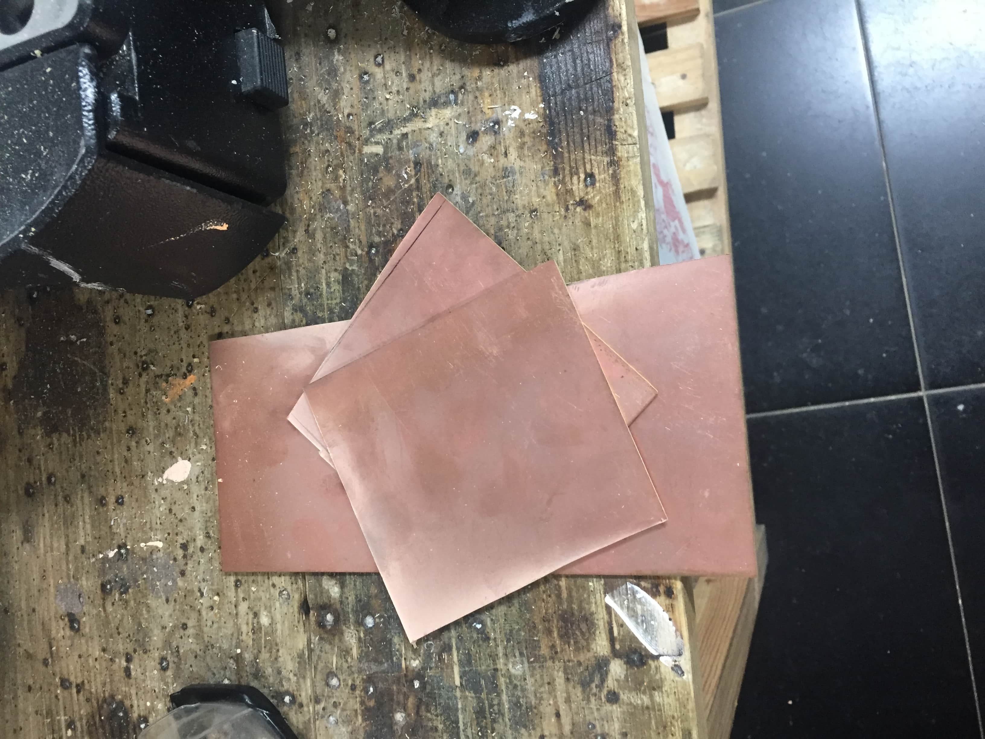
First ,I searched for the available components to see if I should proceed with this controller.So I used an FR1 single side that I cut into the needed dimensions.


I put pin tape and double face to hold the PCB into the bed of the machine.
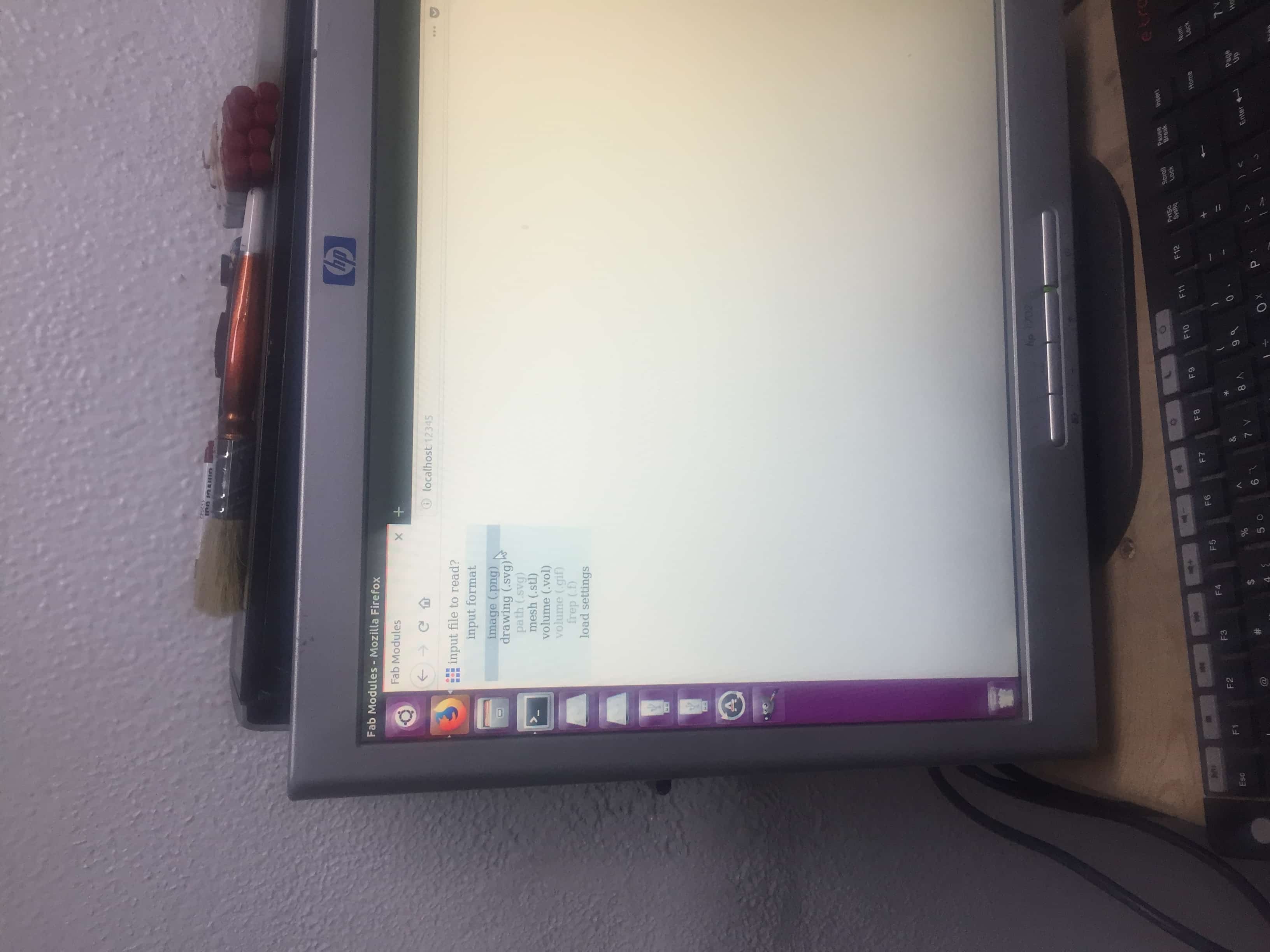
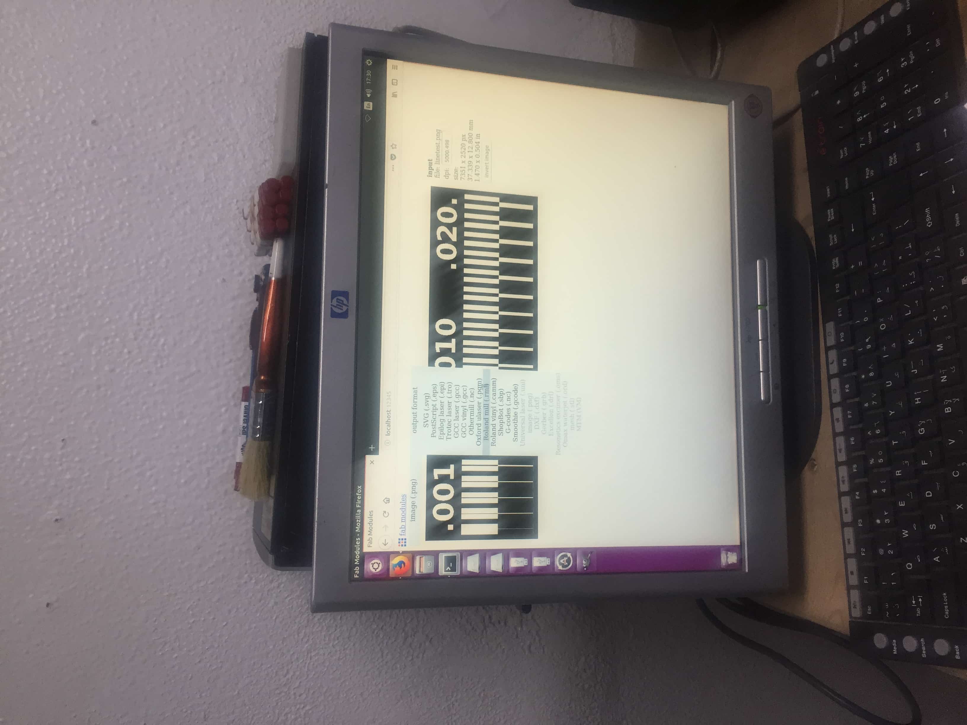
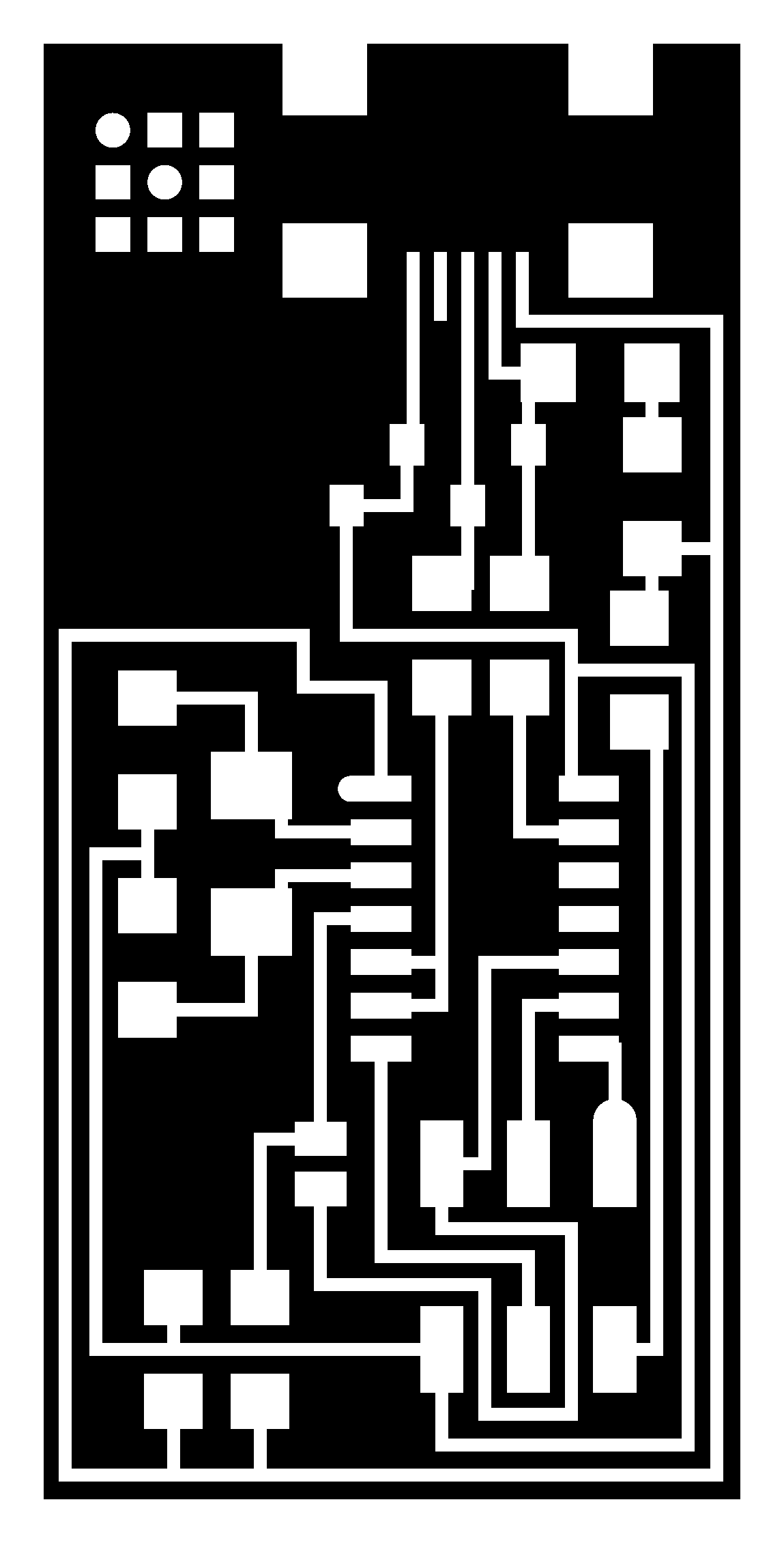
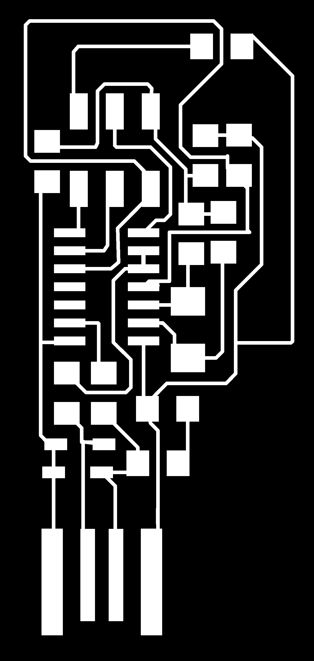
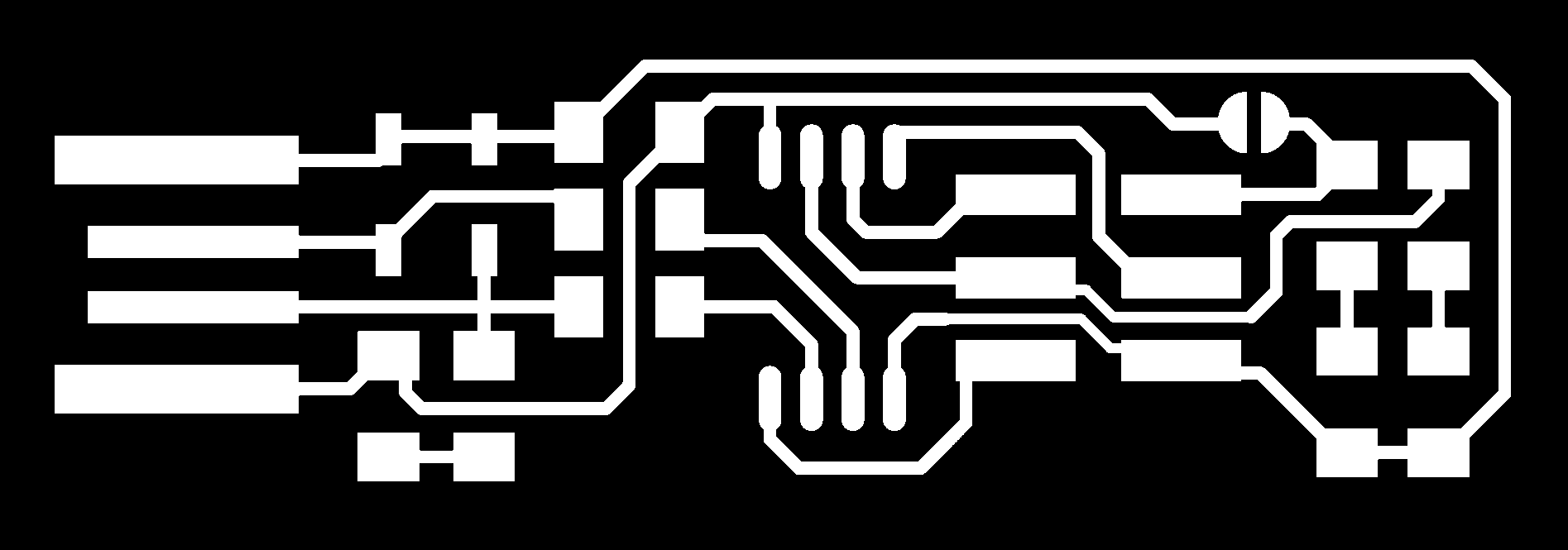
Then I downloaded the PNG files of the circuit.I opened the PC and Fab modules.

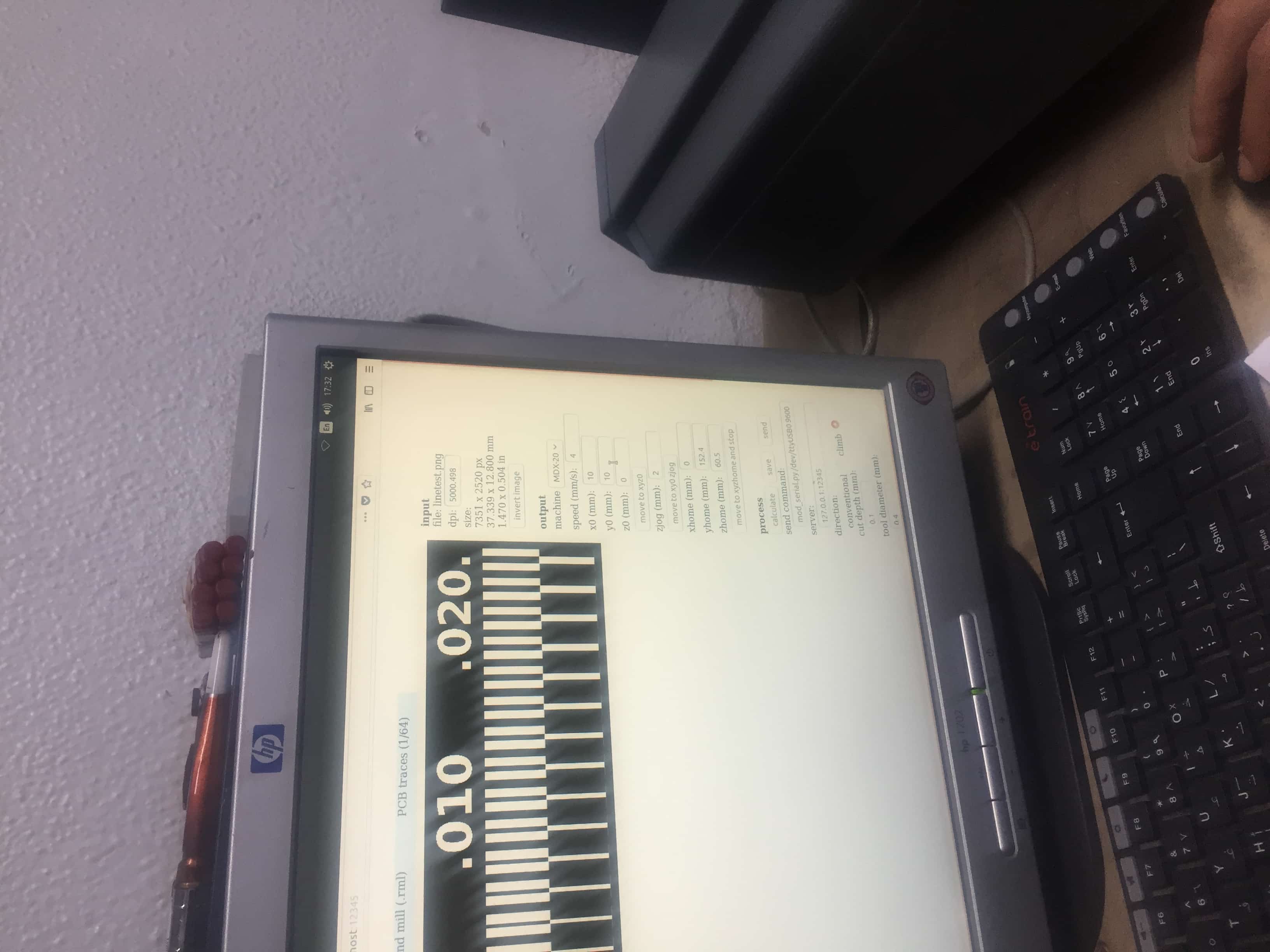
I chose the PNG image/pic,Output Format Roland mill/pic,Process PCB traces 1/64 ,Output machine MDX-20.
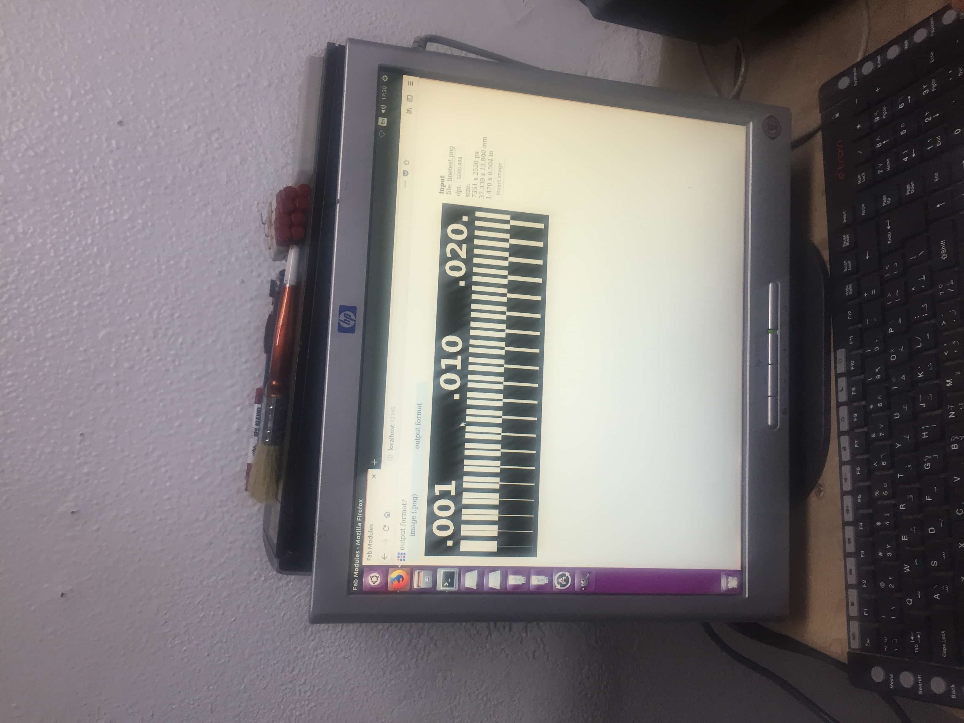
And to get a good finish I made the speed 3 mm/s,cut depth 0.6,climb.

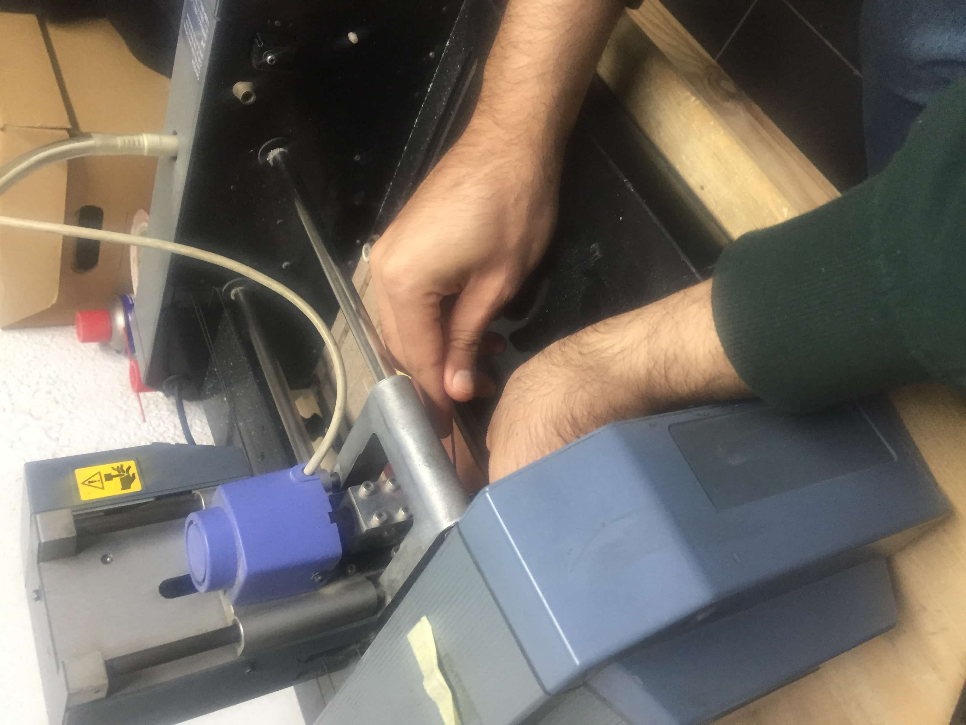
The origin of the tool was set by adjusting in the Output settings.

Then I installed the tracing tool 1/64 and calibrated the tool in the Z-axis.
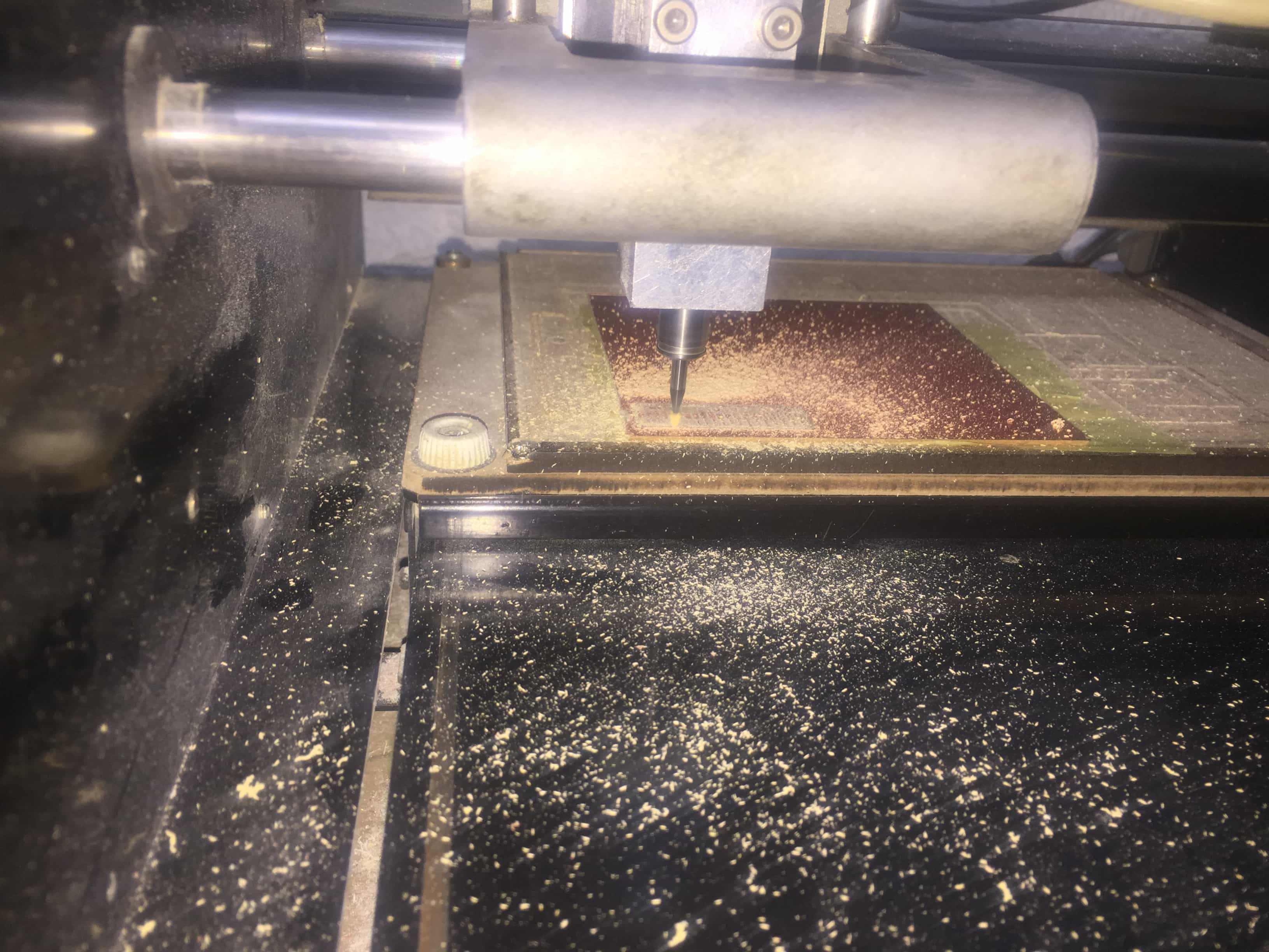
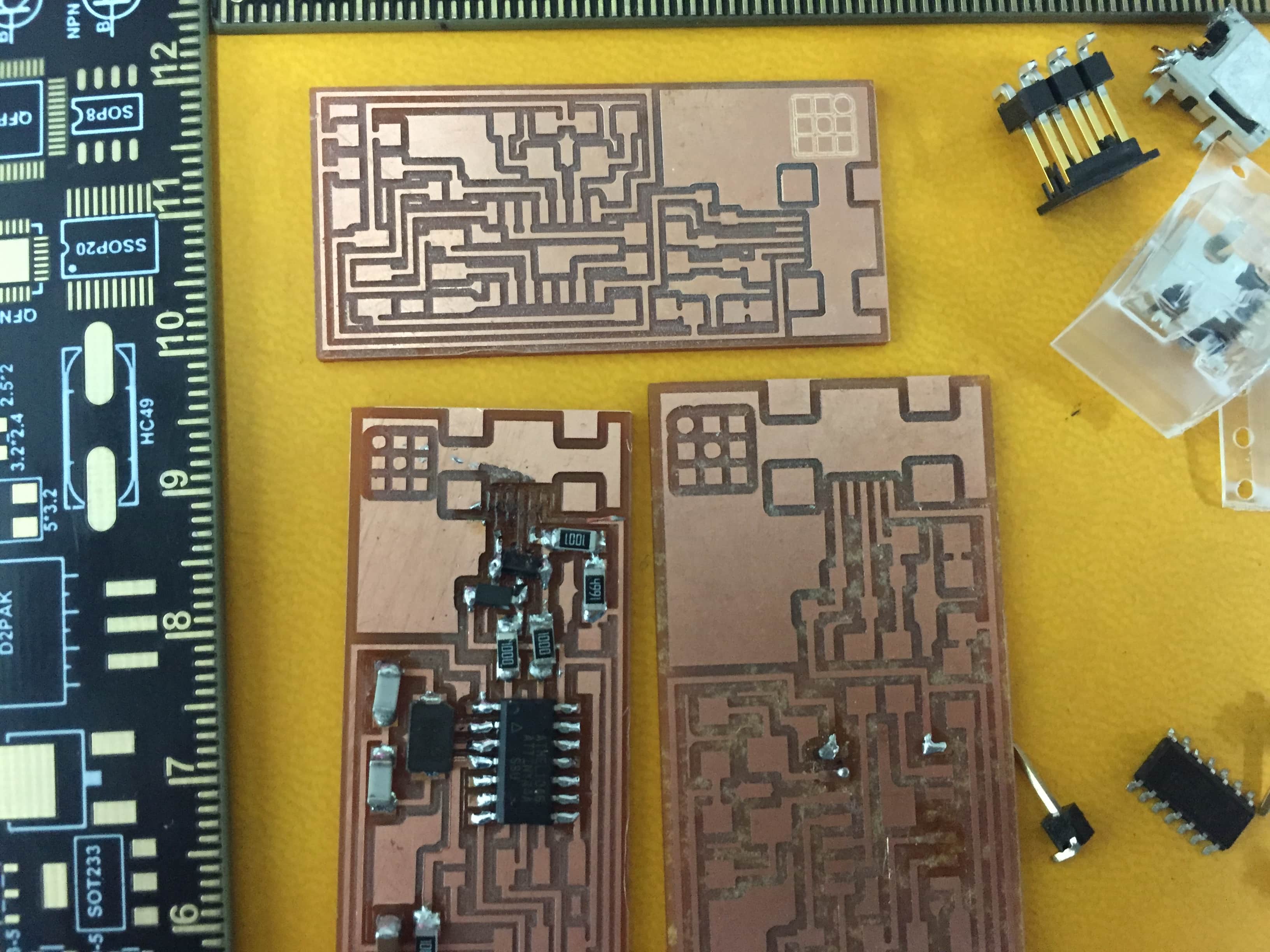
I configured the settings as I was exploring the program .I made a first trial but I changed the dpi so the PCB came out bigger and the components didn't fit.
So I calibrated it.
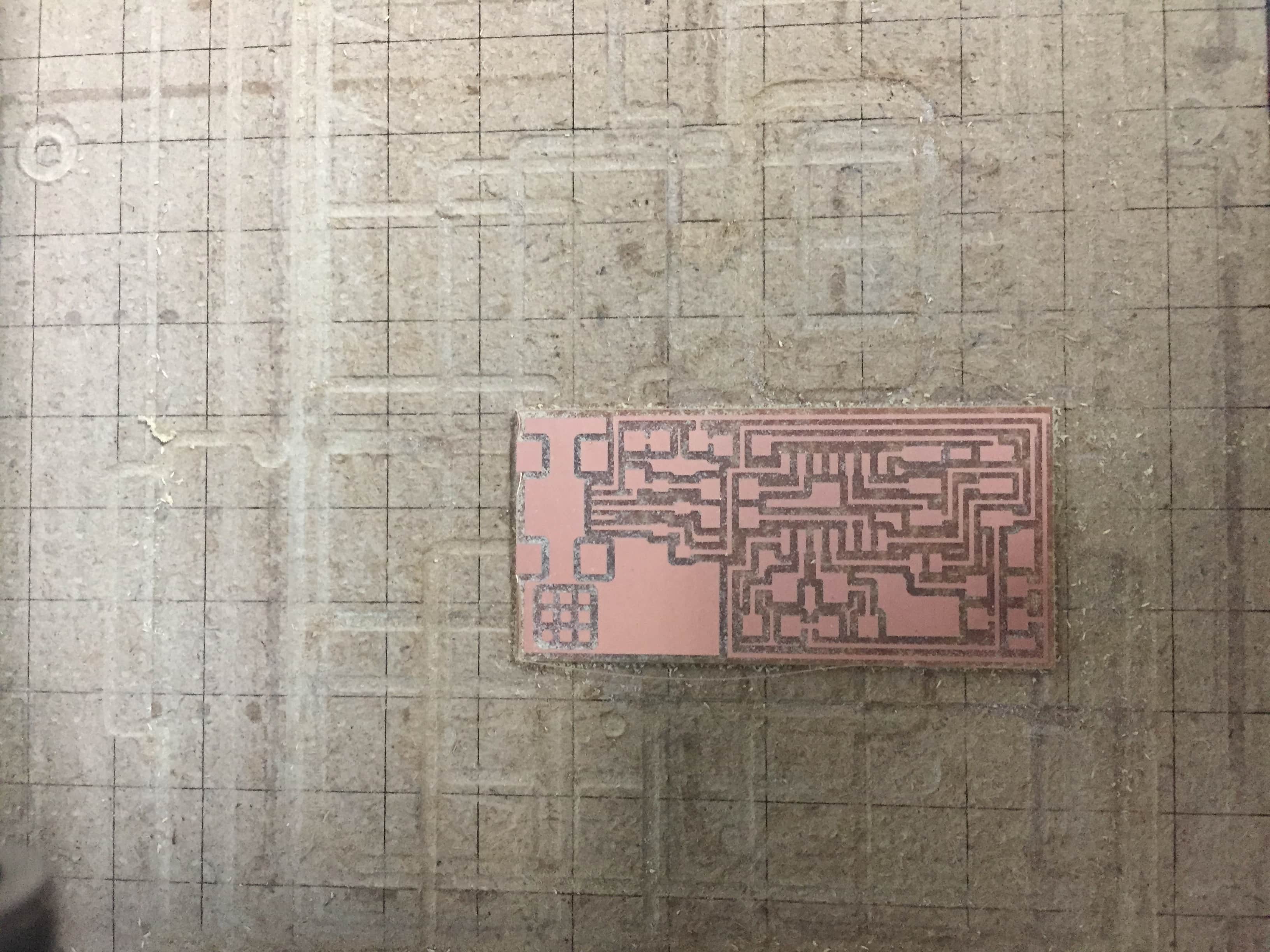
Then for the second trial the PCB wasn't properly leveled so it came out like this.

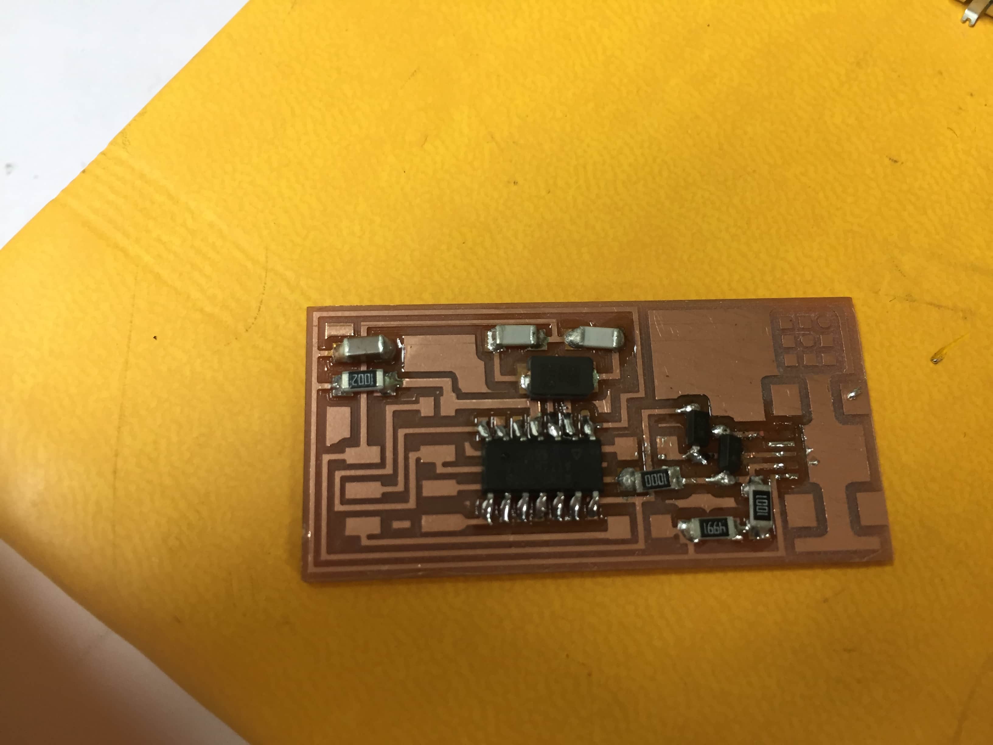
I levelled the pcb on the bed of the milling machine and it came out perfect.
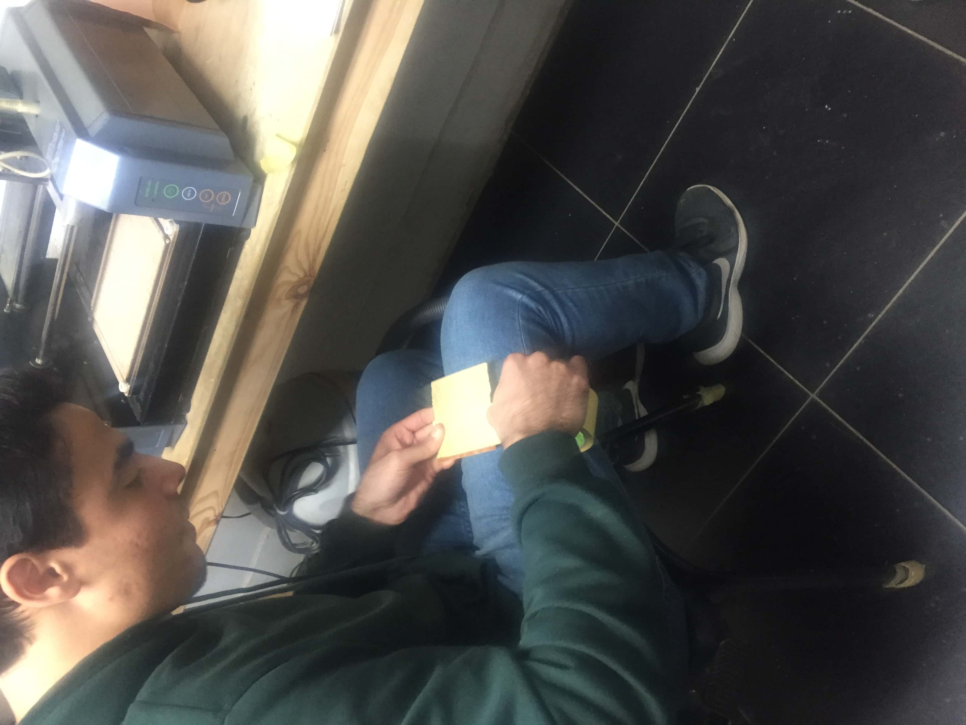
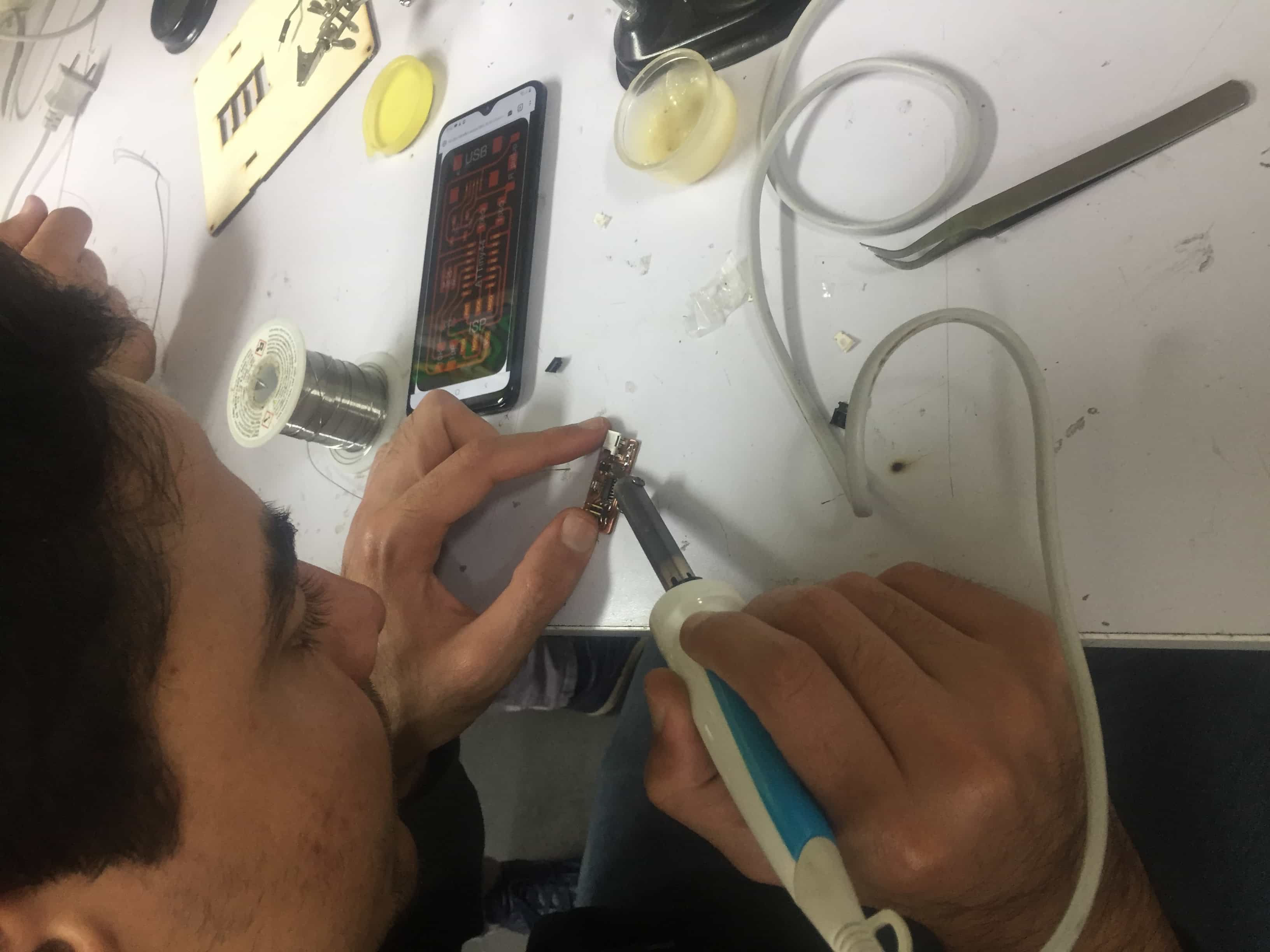
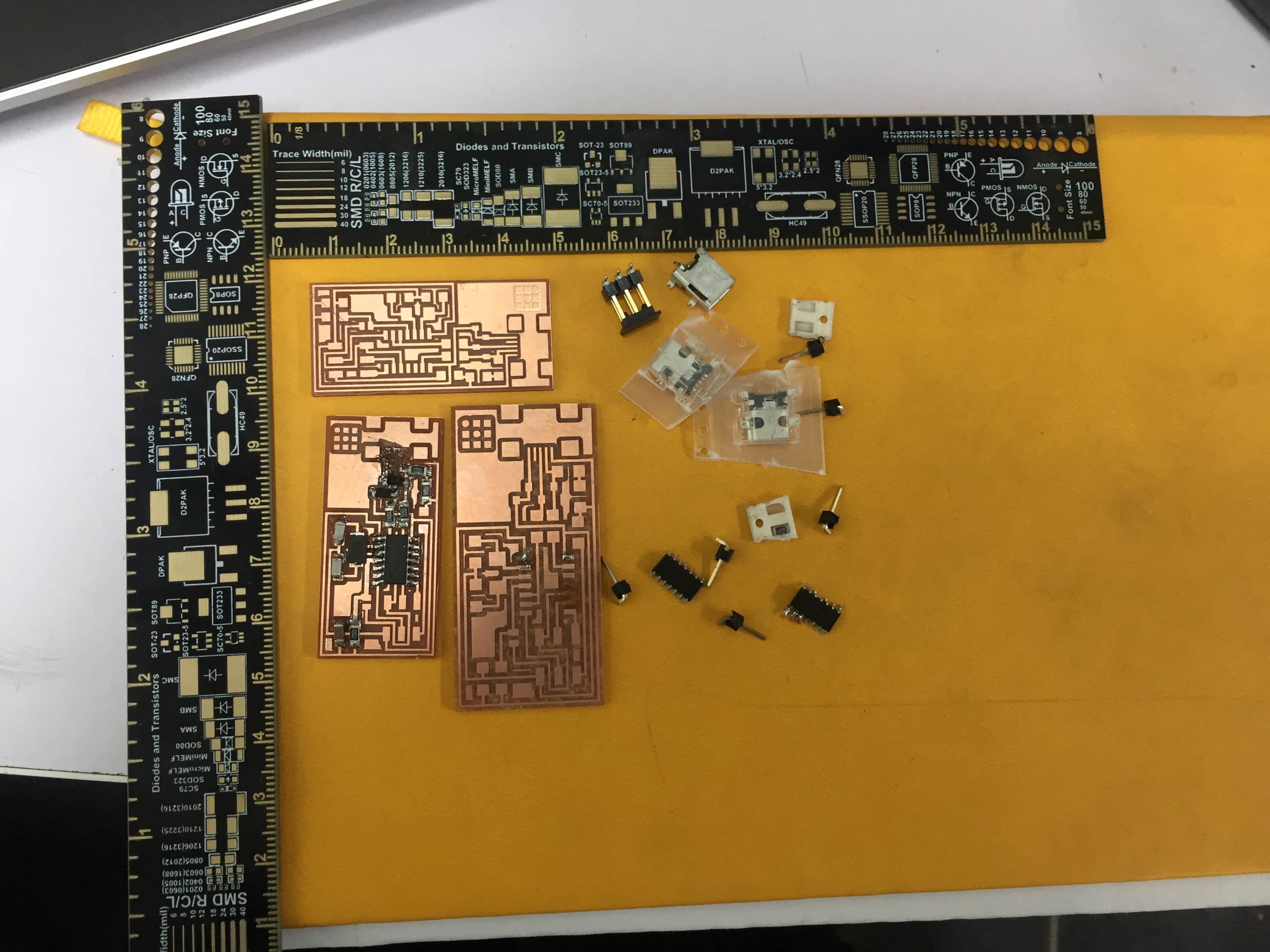
For soldering the components I made trials on the meesed up PCB's so the last one would come out properly soldered.

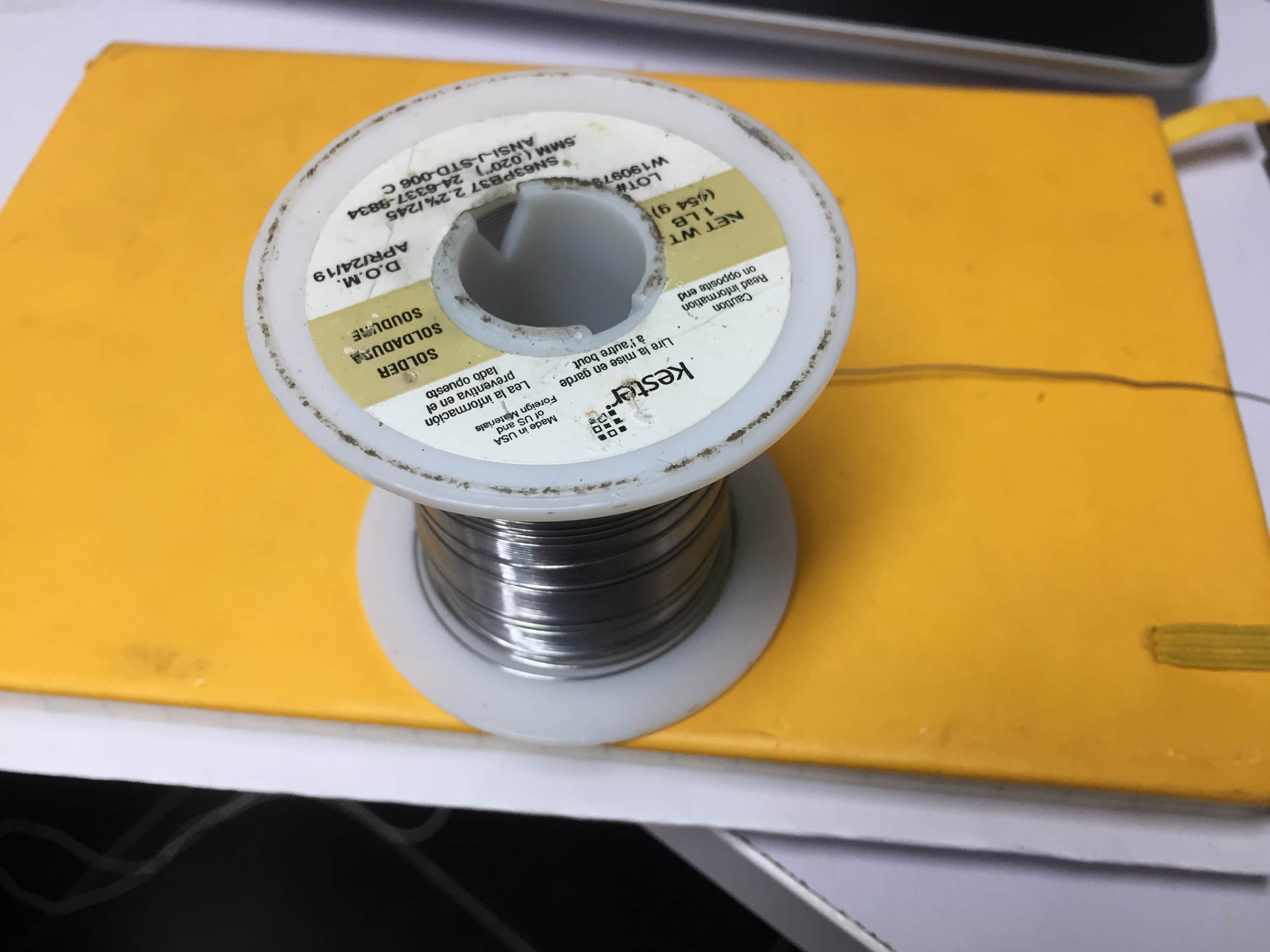
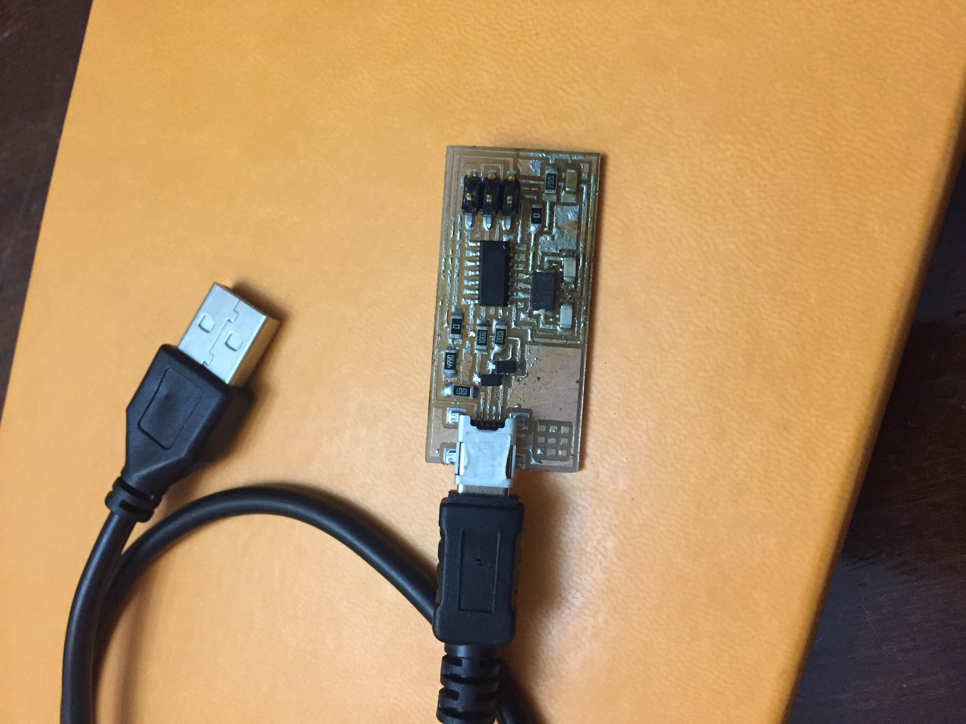
I tried soldering with coper filament.
But for the USB soldering it was hard to use this techninque So
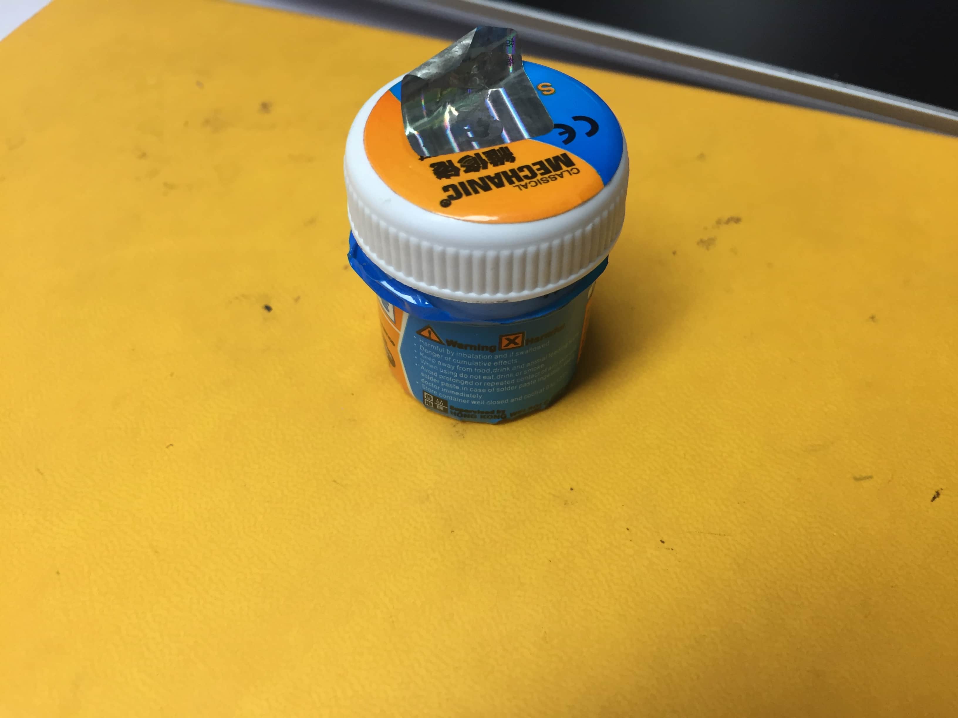
Ahmed Ibrahim advised me to use solder past,I tried it and it was much easier and more efficient.

After that I tried some desoldering techninques using wick and heat,I have to admit after doing some reaserch I learned new trics to desolder without ruining the components and here are some refrences I used.
https://www.youtube.com/watch?v=htrcZuK_ZsY
https://www.youtube.com/watch?v=FV_hmrzD5Uc
https://www.youtube.com/watch?v=mcPpUyOhPr4

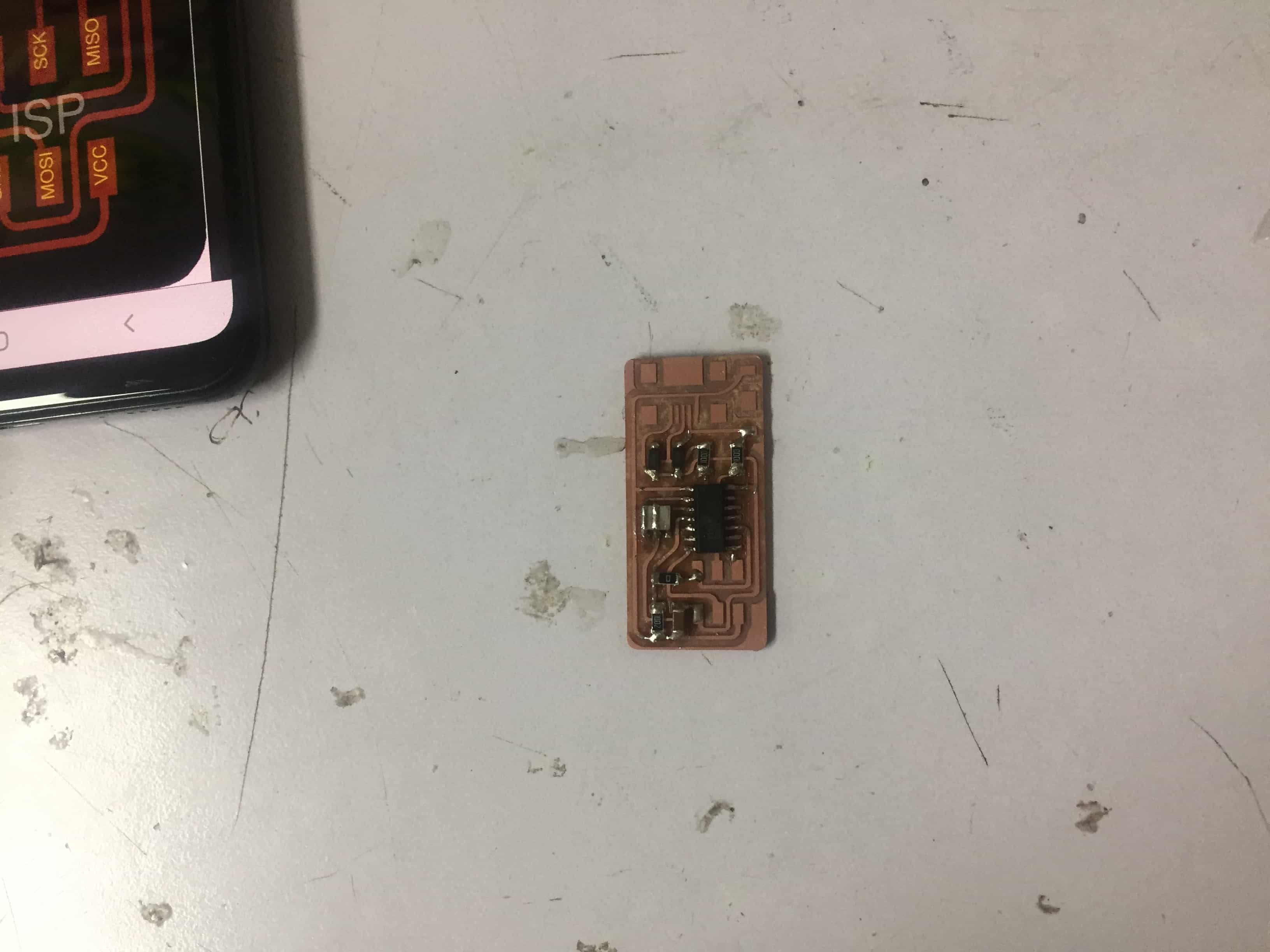
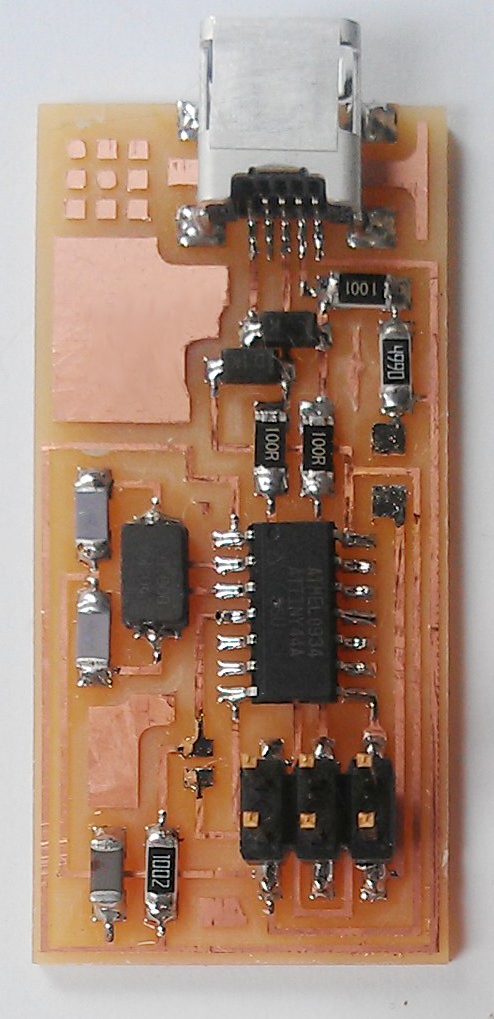
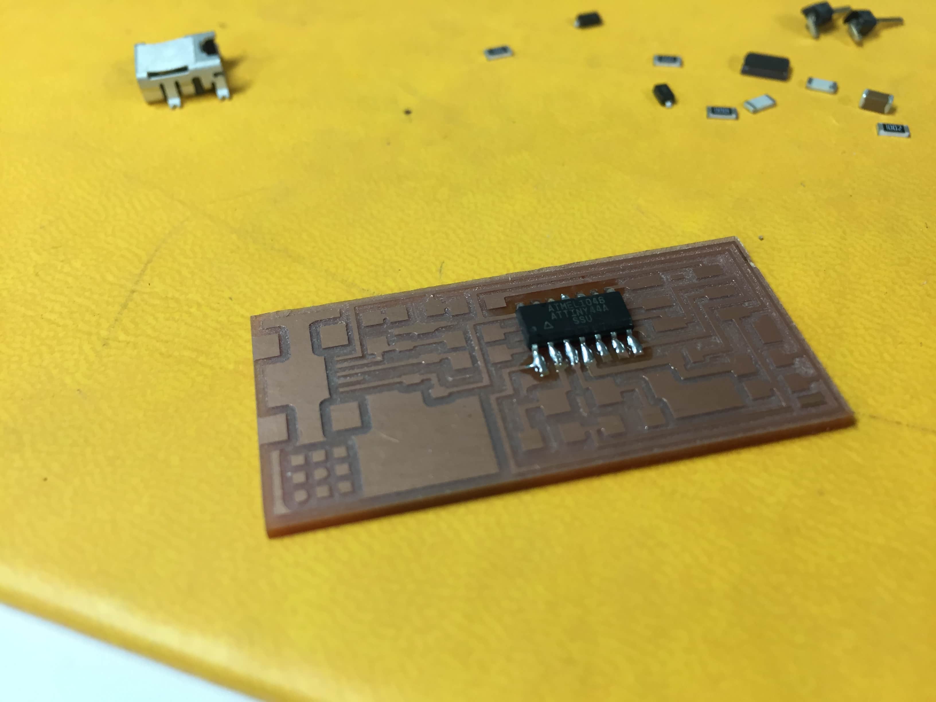
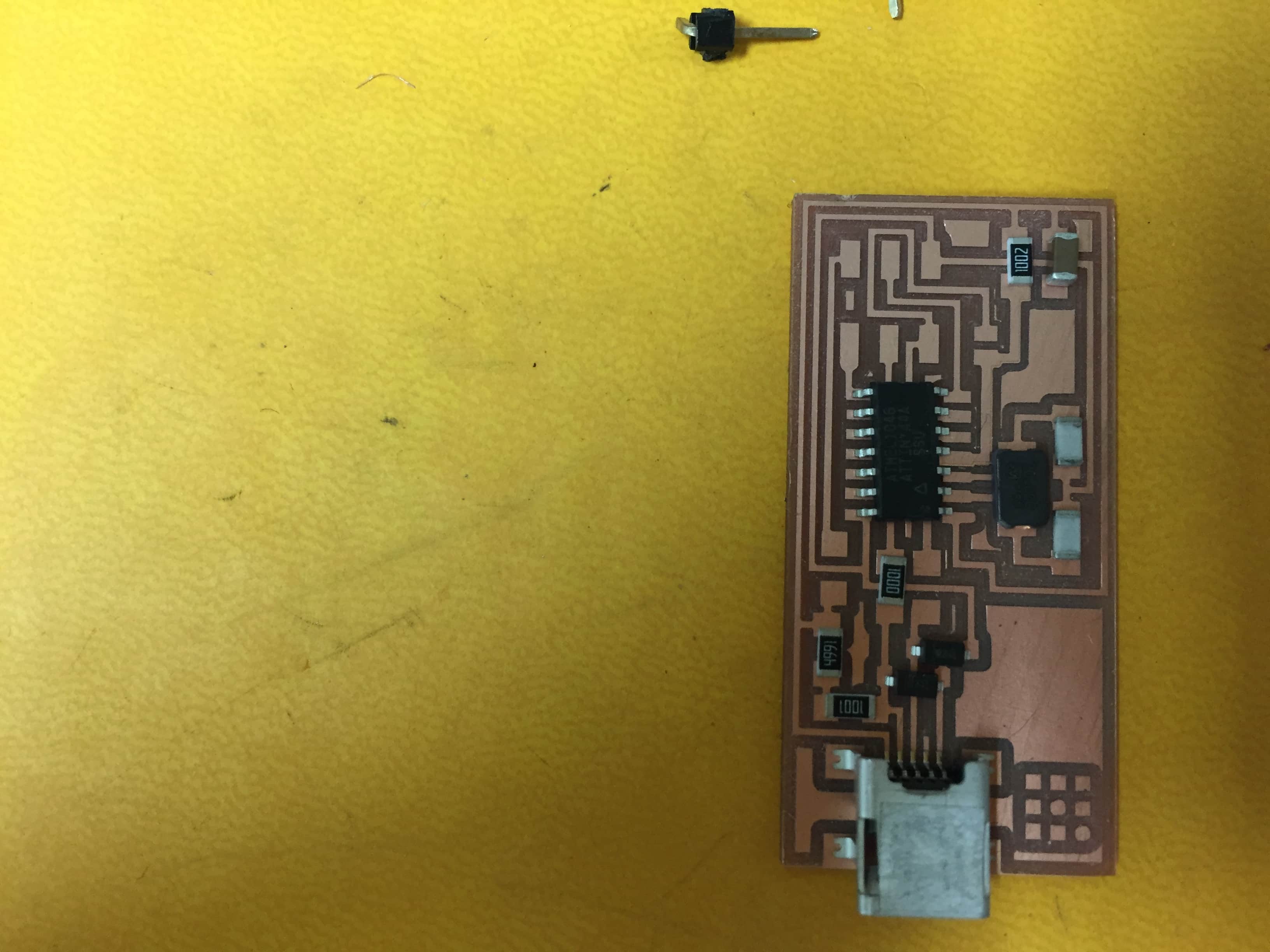
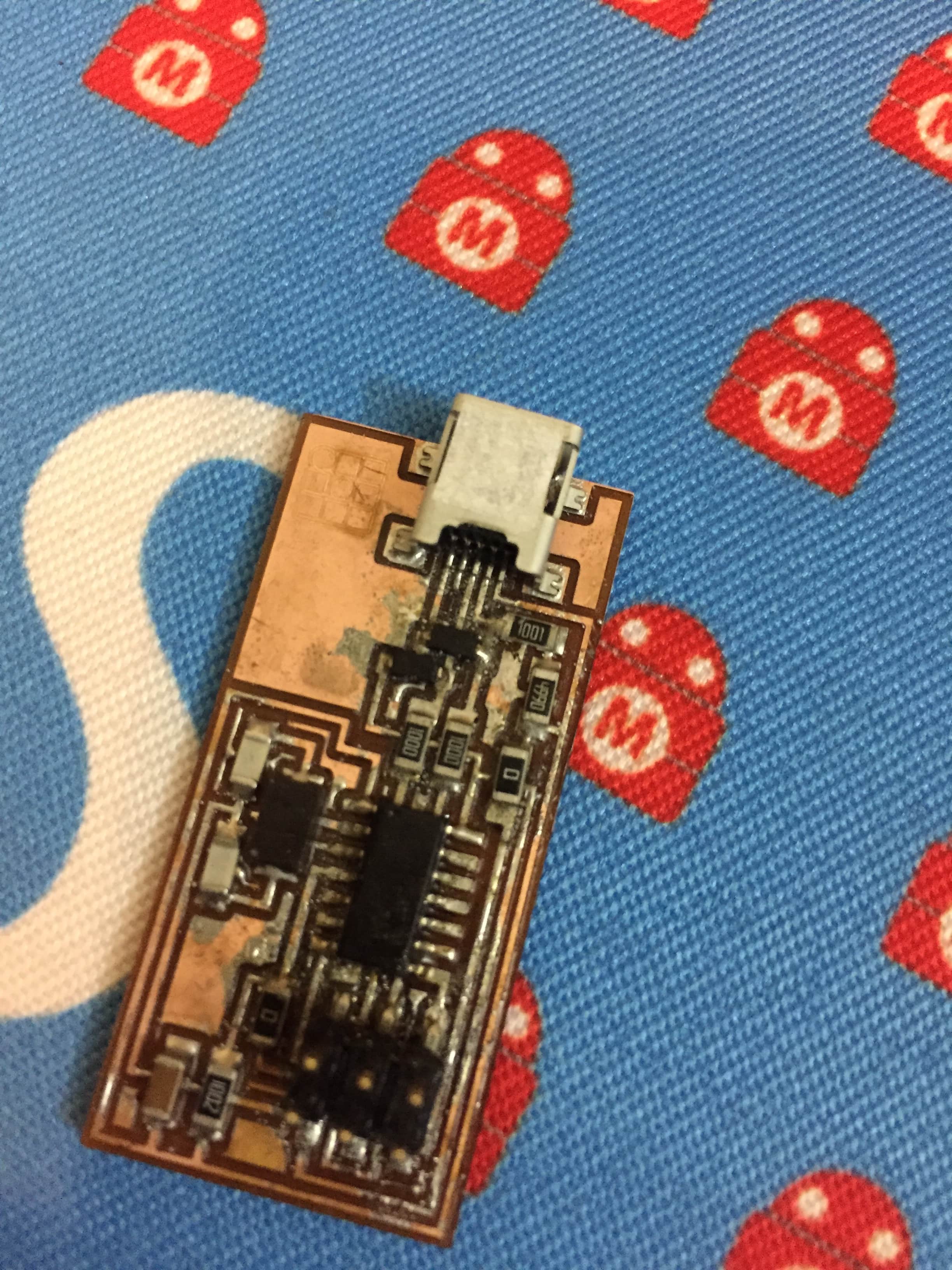
The last PCB came out perfect,it needed to be cleaned up and there was a little bit excess solder.


Now it's time to programe it.I searched the archive on how to program ISP44 and it was helpfull as I had the same dificulteies previous students had and in the documentation they mentioned how they overcome it ,like Nada's page.
This is why I would like to thank them for their brillinat documentation.
I had the same problem that the driver is not compatible with my windows after research I found LibUSB... that worked from the documentation of Nada who faced the same issue last year.
I installed it and programmed the controller with arduino uno to set up the firmware.

After that I want to try to program with the ISP44 to see if it works.
So I followed the steps in this tutorial:
I downloaded Winavr.
Also the Firmaware
and Zadig from Nada's documentaion but after many trials the ISP44 just does not get recognized.I followed many documentations like :
Mrehan El Shahawy ,
Nada,
Lamia,
I consulted our mentor
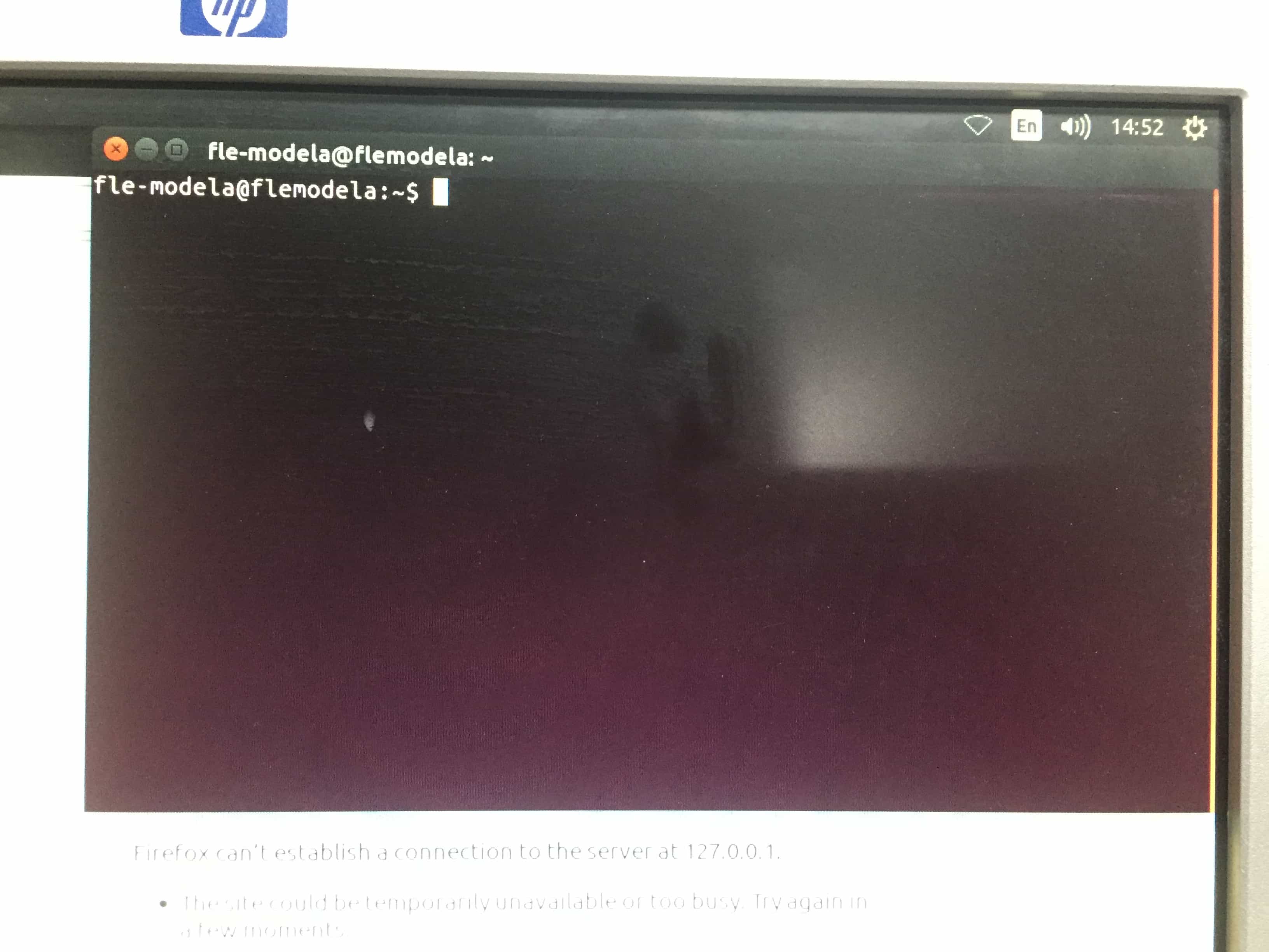
Mohamed Kamel ,he advised me to connect the ISP to a pc that have linux or ubuntu,to know if the issue in the board or in my PC,Maichal Rezkallah proposed that maybe the zener diodes are mounted in reverse.
To sum up the problem is: the ISP44 does not get recognized on my PC ,possible reasons:
1) Maybe it's my PC.
-I connected my ISP to a PC that have linux and checked:
2) Diodes mounted in reverse.
-So I reviewd the diodes polarity, it was correct also to be sure I reversed it and it didn't work at all, so this is not the reason.
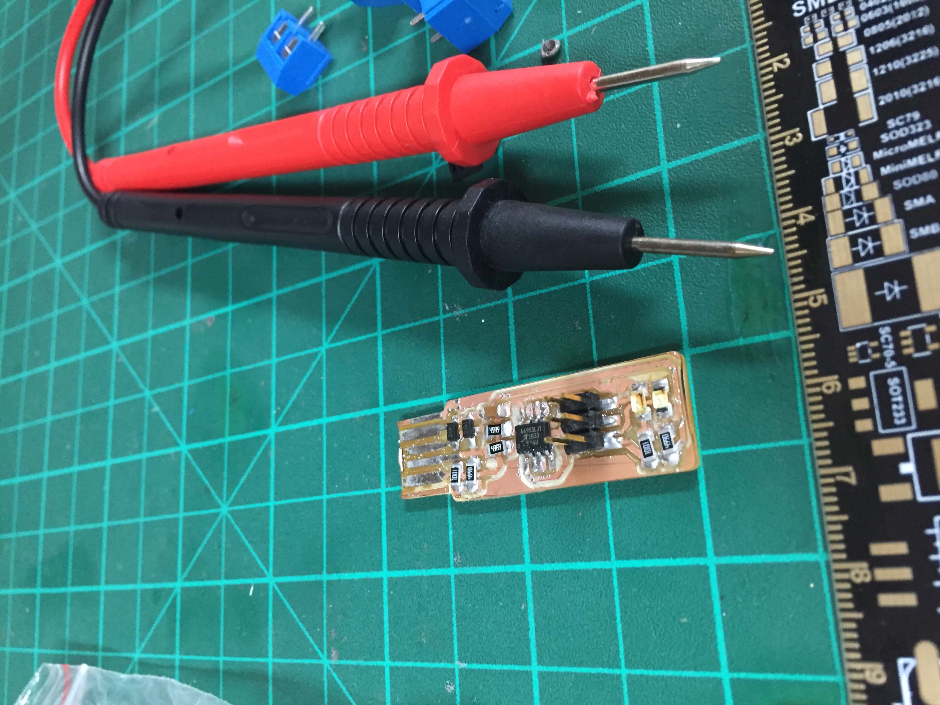
3)Soldering issue.
-I tested with multimeter the joints, it was fine,not that one also.
4)I'm doing something wrong in the programming phase maybe I missed a step.
-I redid the steps following the link:...
- I doubted that maybe I'm doing it wrong or I missed a step ,so my little sister Mayar she is in her final year engineering computer science she helped me out redoing the steps,still that is not the reason
5)One or Some of the components are damaged.
Actually I viewd the documentaion of fellow colleages at Fab Academy I sent an e-mail to
Row'a Othman : she is a fellow student at Fab Academy this cycle from Fab Lab New Cairo, I asked her to send me the tutorial she followed to do this assignment ,she was graceful and replied to me and sent me the link,I'm so gratefull for her.
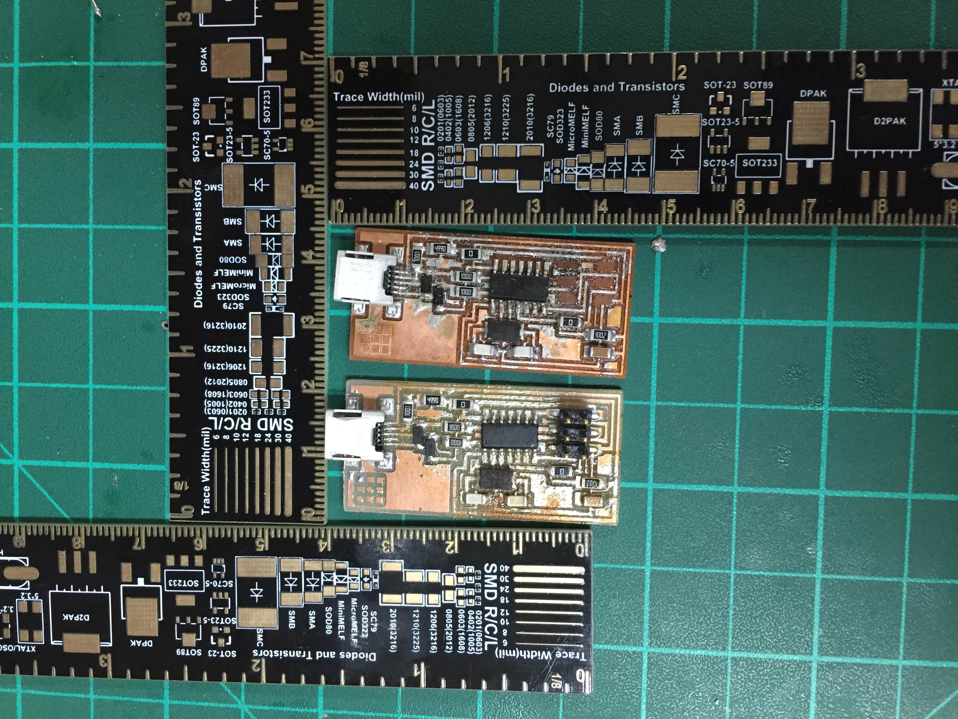
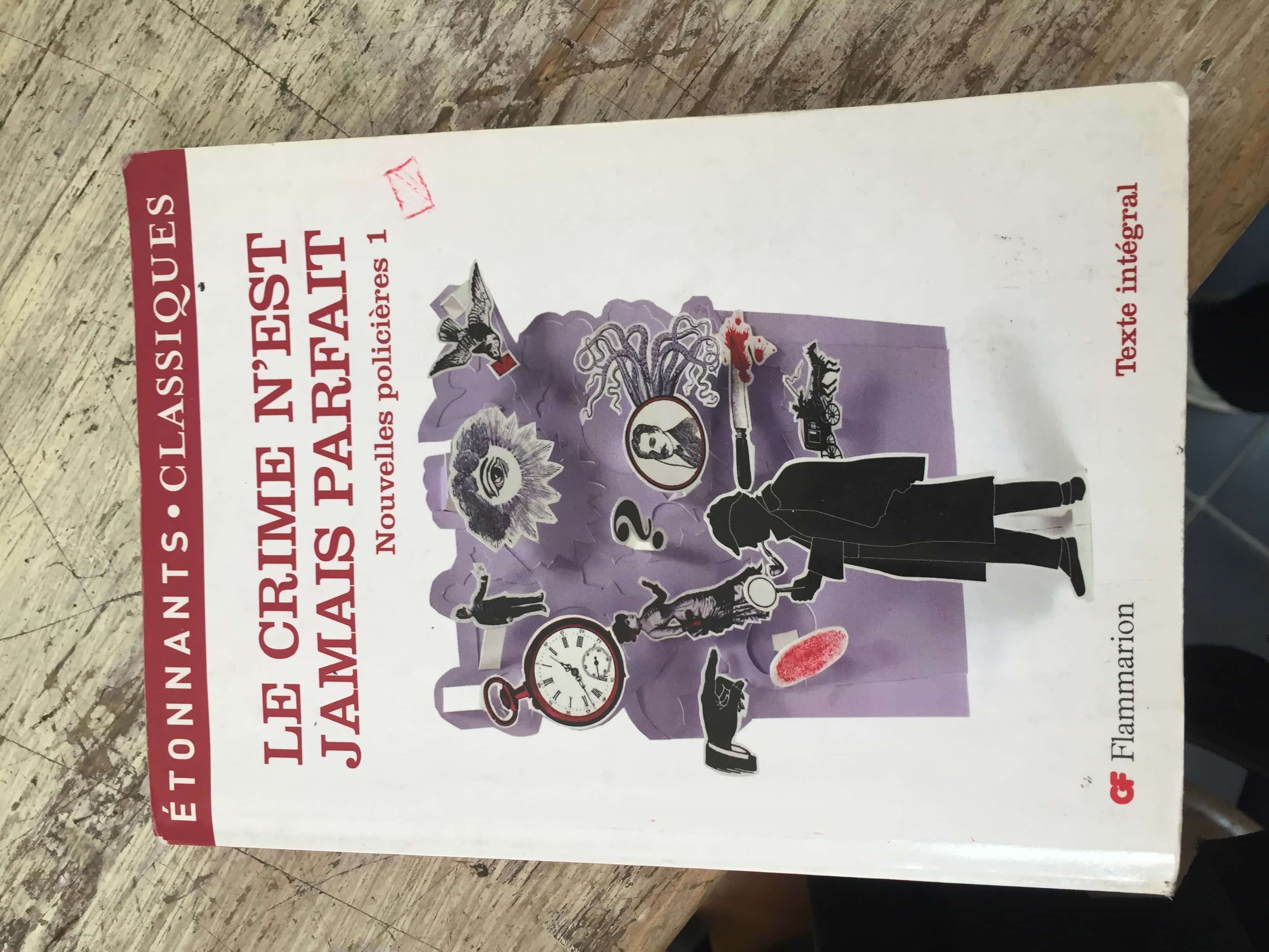
To proceed I made a new ISP 44 also I made 3 other programmers not all of them using ATtiny 44 and I will try them and for the sake of limited time I will use Atmel ICE to program and if there is time left I should redo the procedure just to make sure what am I doing wrong: As Fran said in the debugging recitation :"You are the detective in the crime you did "
IS it a sign I was just reading this book !!!
Those are some tips and tricks I learnt in the debugging process:
-Begin debugging with a clear mind.
-Patiance is a virtue in this process,you could be lucky and solve the problem from the first trial or you could spent hours debugging :"make it work" as Neil says "It either works or not".
-Don't drink coffee before it, your hand will shiver while soldering.
-At the begining ,list all the possible reasons for the problem and possible solutions and write them down on a paper.
-After every solution you try ,check it on the paper, just to be organized and not to get lost.
-The most important thing is to know: why it does not work and why it worked this is crucial in the learning process.
After some time of debugging
I figured out why it didn't work and here is why:
I used solder paste and heat gun to solder the components.While soldering the ATtniny 44A and resonator I kind of did excess heating and during my research for the bug I read that extra heat ruins the resonator ,I should have been more careful.So I changed the microcontroller and resonator and it worked : by worked I mean that the board wasn't recognized by atmel studio in addition to not being read from the PC but when I figured the reason and corrected it , the microcontroller's signature was read by atmel studio.
I just have to say the following :
All the time I spent debugging this controller saved me a lot of time in the upcomming PCB's .I got to know the common mistakes and debugging strategies,I was introduces to some intersting blogs for debuging.
The other 3 programmers I produced are :
-Valentine
-Zaerc
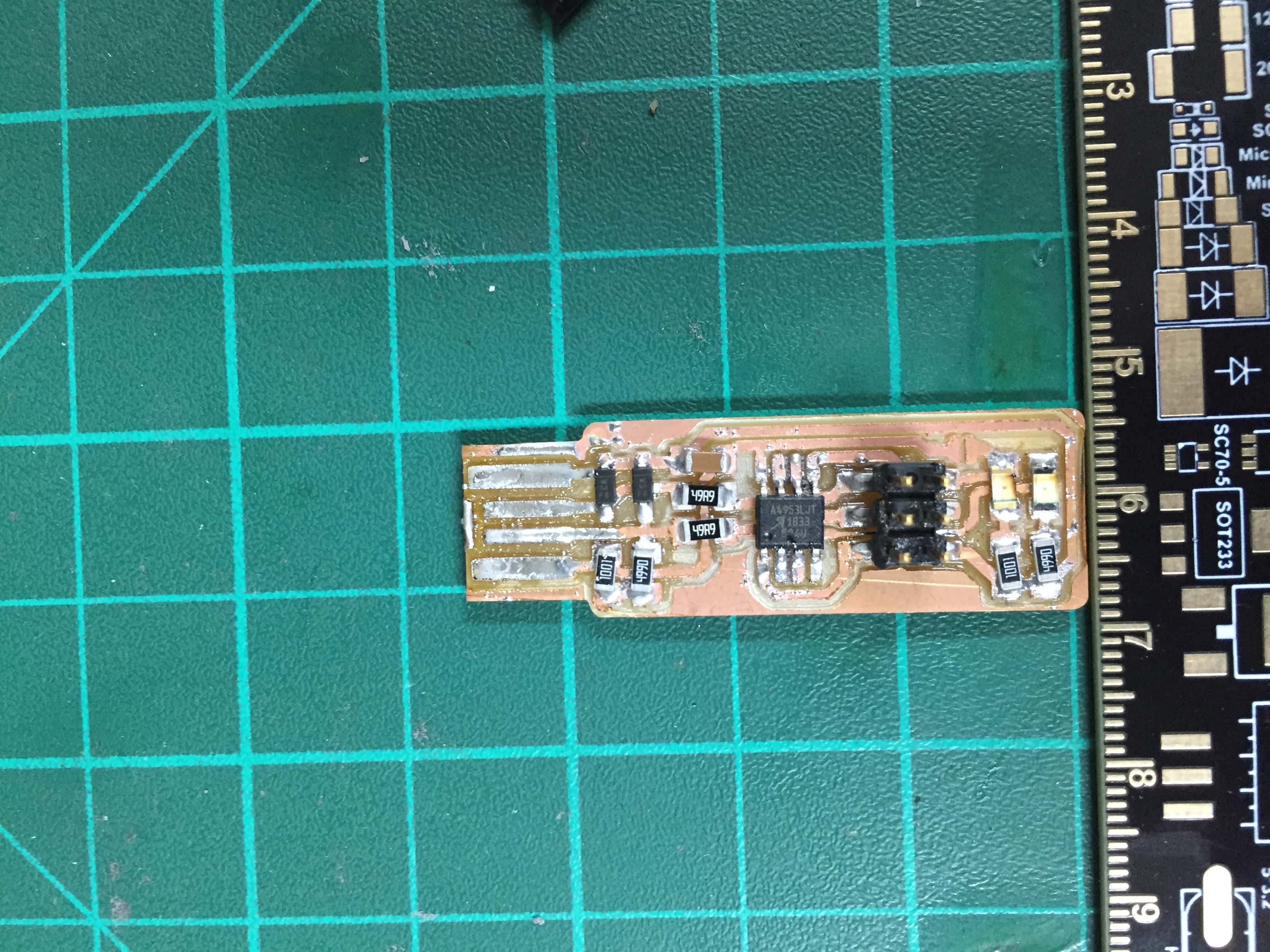
-Alex

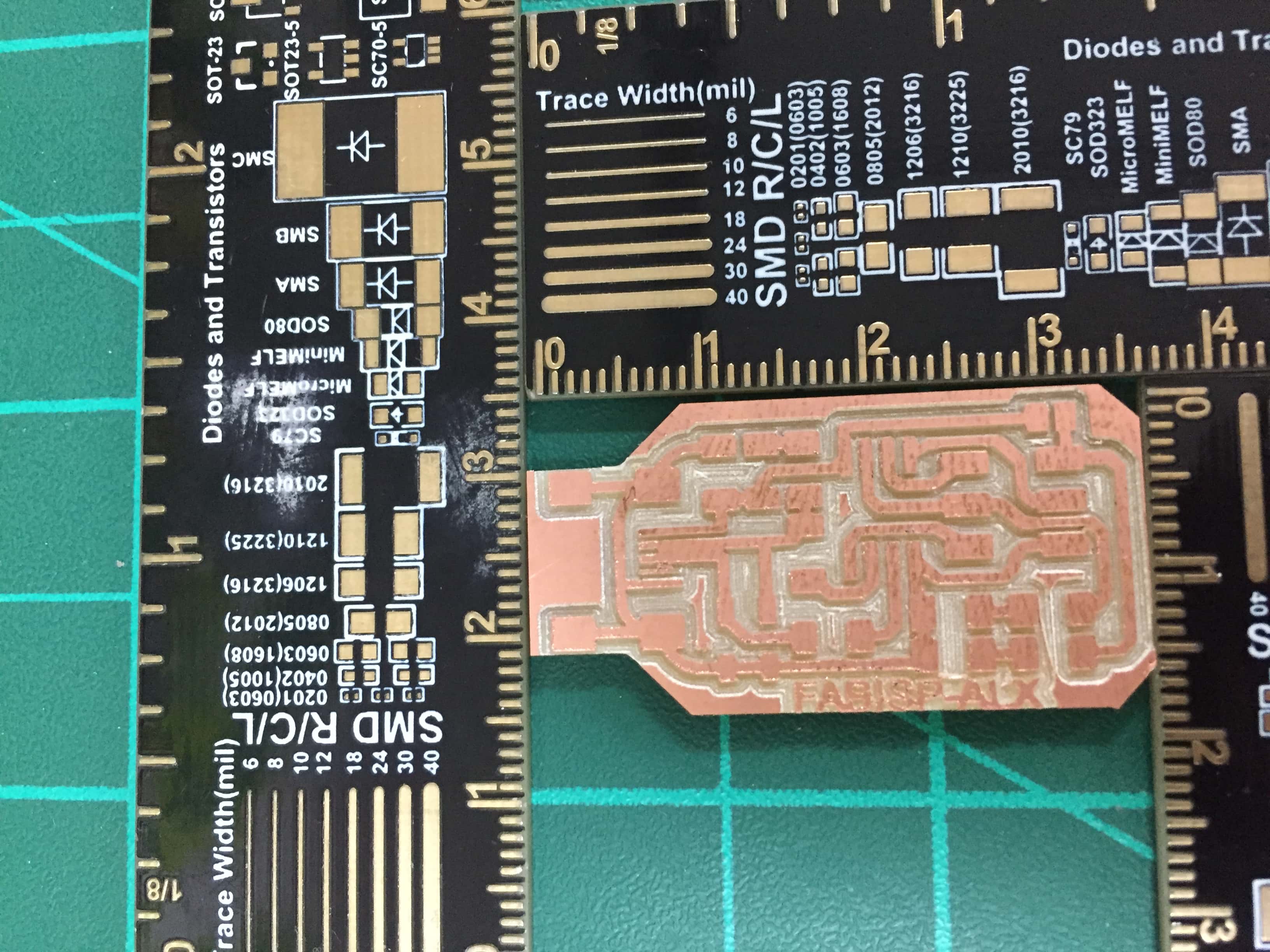
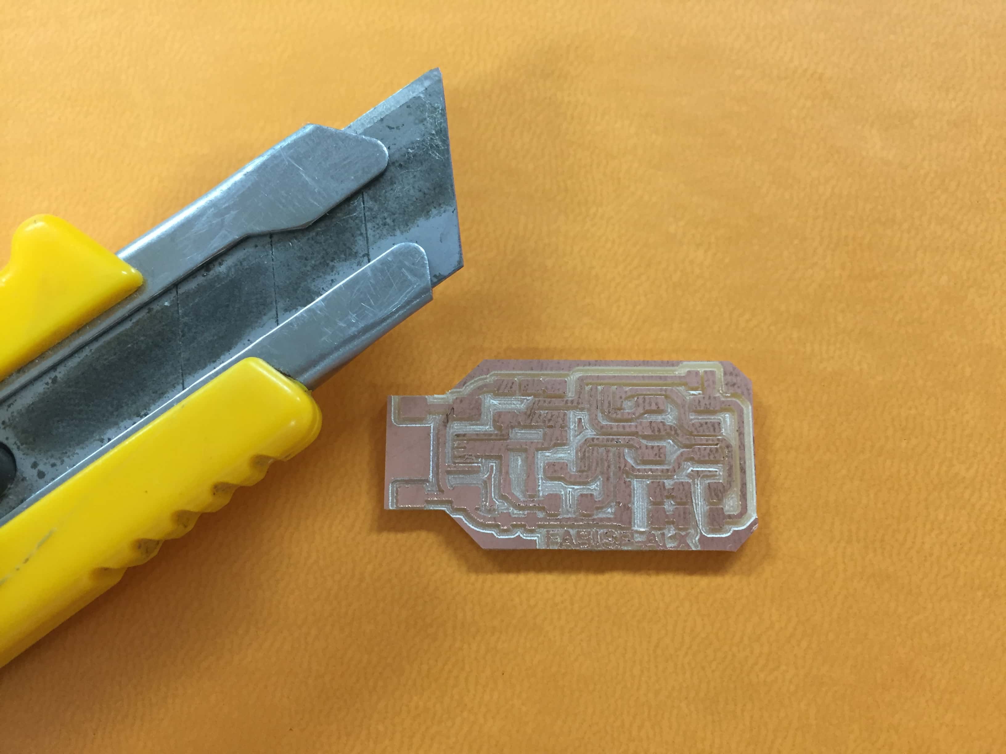
Same producing steps as before.