Mechanical Design.
So I discovered at the last moment that I will make this assignment totally with myself so I decided to make a simple 1-week project as professor Neil has said.
So after a lot of thinking I decided to make a camera slider with a Bluetooth module so I can control the movement position and the movement speed.
Bill of Materials
- NEMA 17 stepper motor
- Arduino Uno
- CNC shield v3
- A4988 driver stepper motor driver
- 2x 8mm hard chrome rods 400mm length
- 3D printed GT2 gear
- 3D printed 2x LM8UU linear Bearing
- 624ZZ*1
- 3mm and 4mm screws with nuts
- 8mm threaded rod with nut*4
- camera mount screw
- HC-05 or HC-06 Bluetooth module
CAD
For the Cad design, I had been inspired by Drawing Robot design and Mahmoud Alaa CameraSlider.
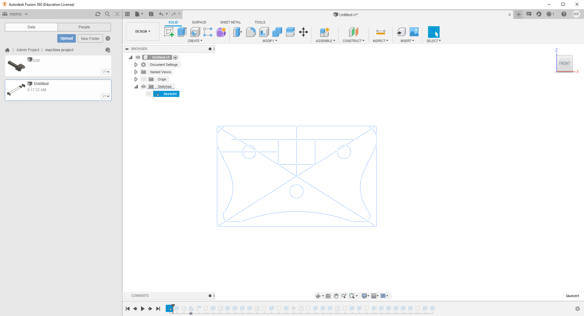
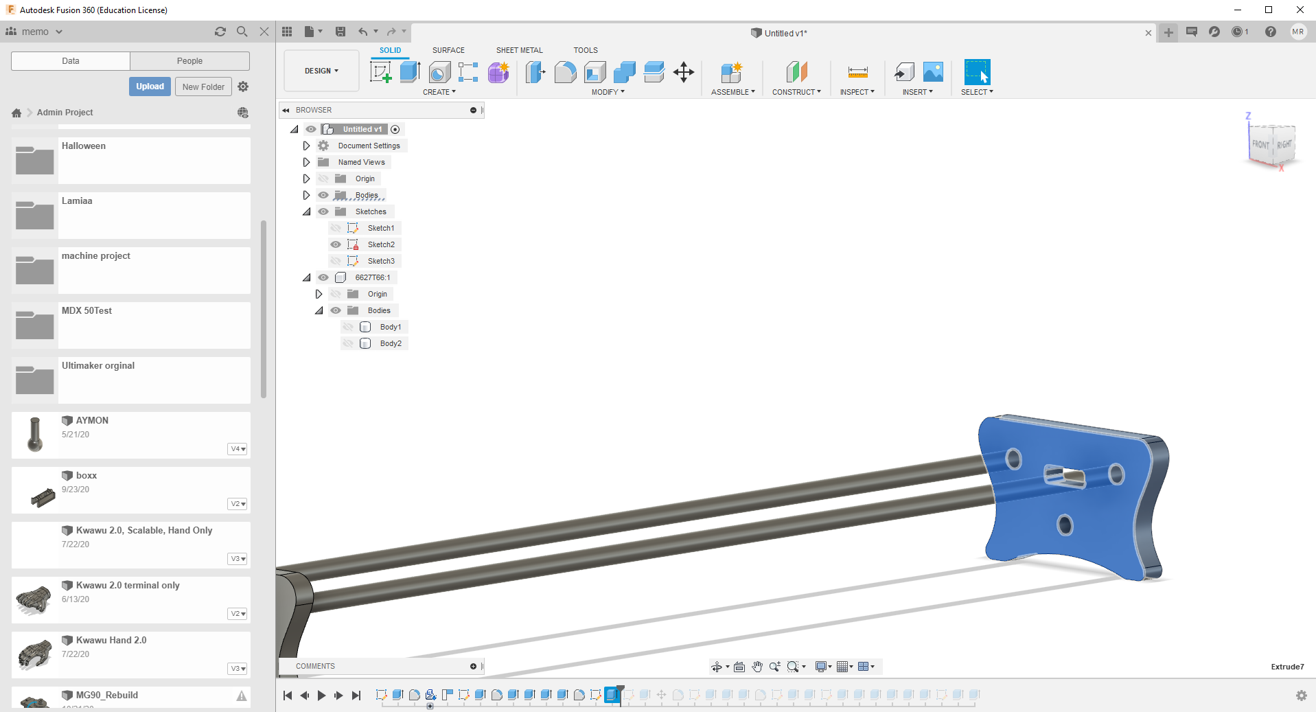
For a start, I scratched the Face of the axes I want to make I started with Basic Shabe I added the smooth rod size and the size between the rods because it will control the size of the phone or the camera mount
I add an 8mm threaded rod to stable the camera slider and give it more weight.
Next the motor holder, so I added a Nema 17 stepper motor from “McMaster-Carr” tool in fusion,
Next is to move the motor and create a scratch to make the motor holder.
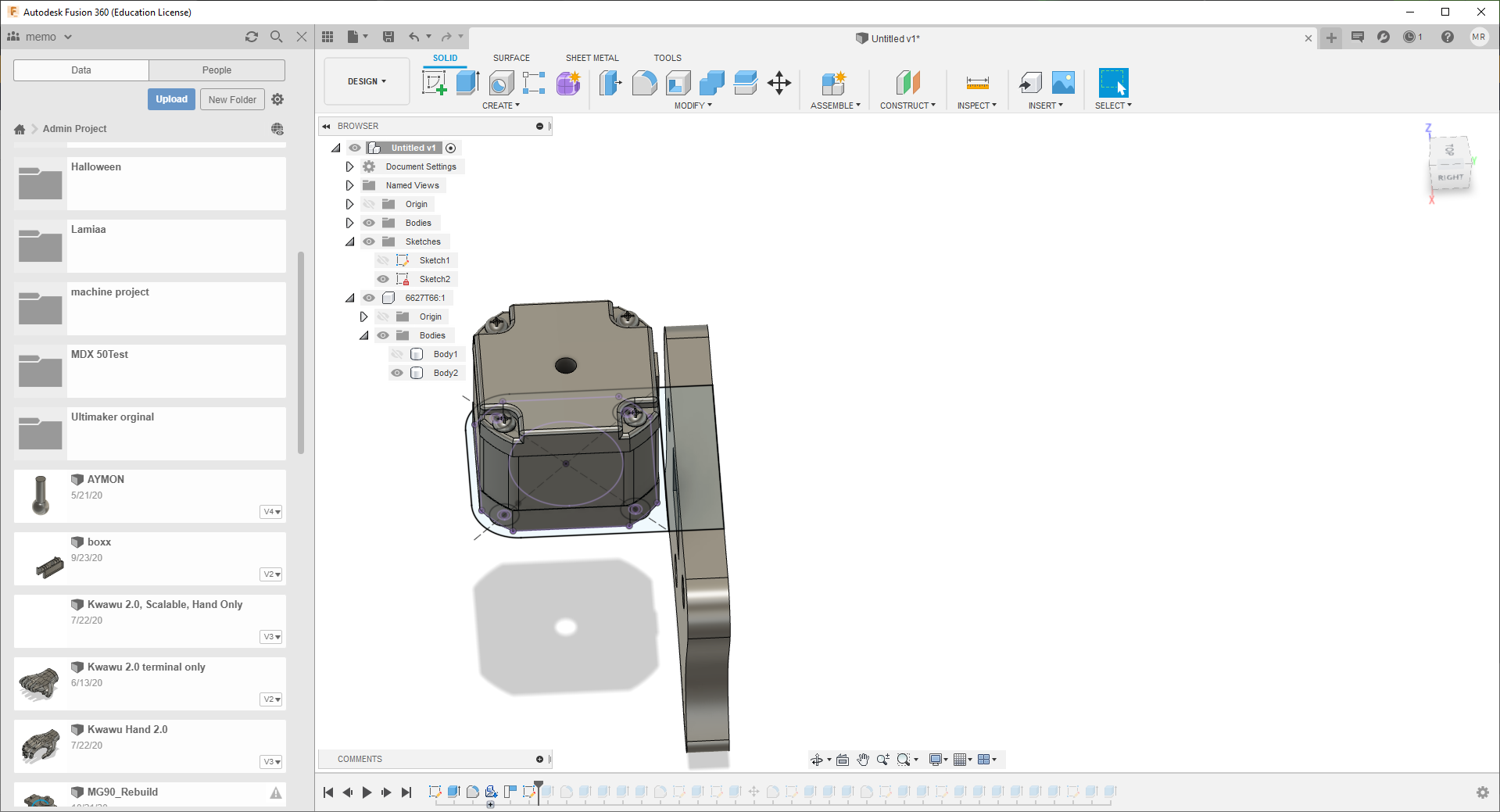
I Used the “Fillet” tool to make some strings on the stepper motor holder.

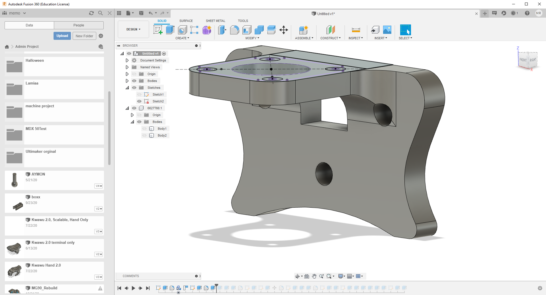
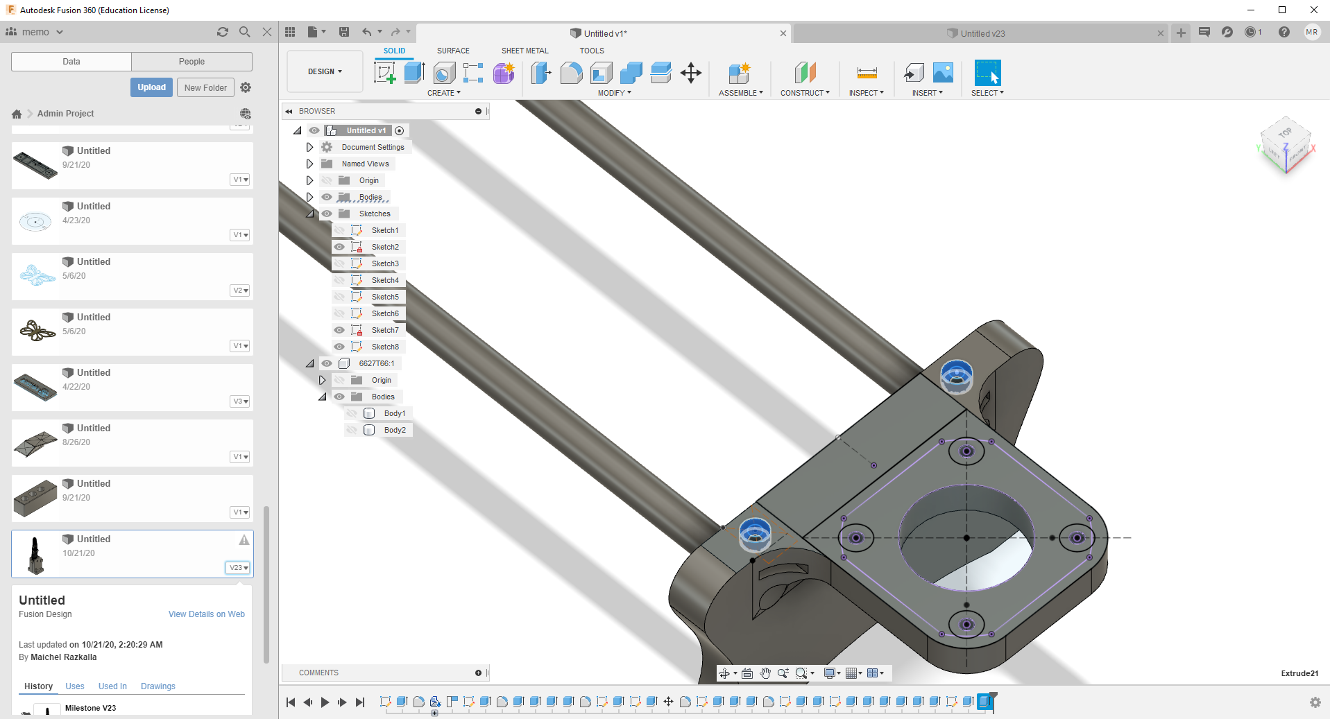
Now for the next part so I used the same face scratch of the first part with small details like adding a place for the 624ZZ to hold the Gt2 belt.
Next, I add some holes and nuts in the four corners to hold the smooth rod.
Now for the camera holder, what was in mind is to make a holder for the LM8UU 8mm Linear Ball Bearing with a flat surface to add the camera holder.
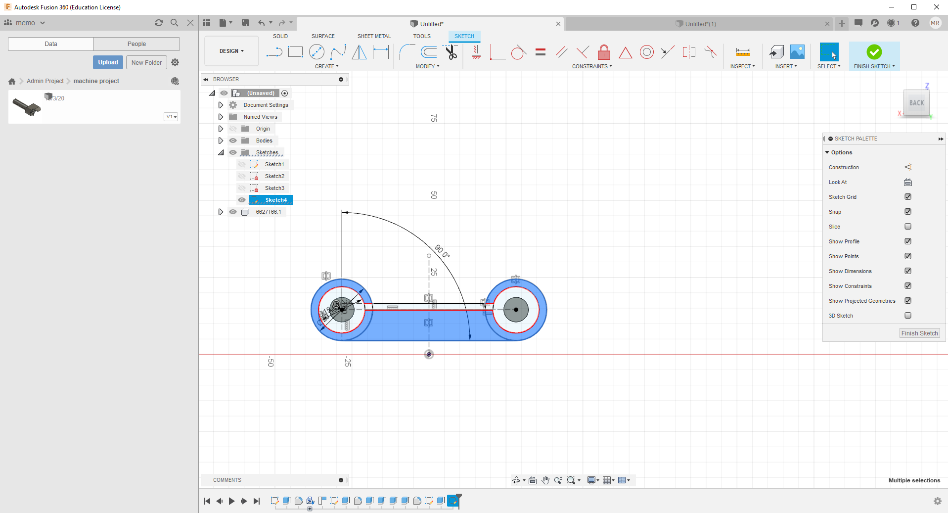
so i decided to make a small shaft to hold the GT2 Belt
Now the CAD Design in completed
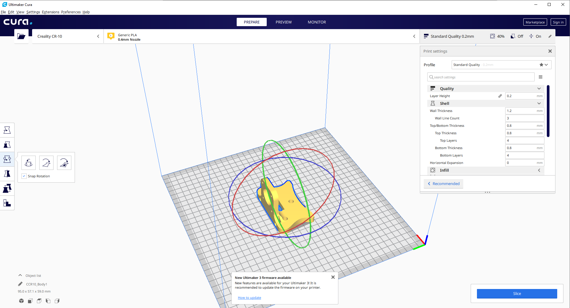
Printing settings
I didn’t need high quality in these prints because mostly its basic shapes the printer can handle it easily as I understand for that I will make the layer hight 0.2.
For the wall thickness, I make it 1.2 to be hard and could handle hammer knock, last is for Infill structure I make it 40% for the same reasons
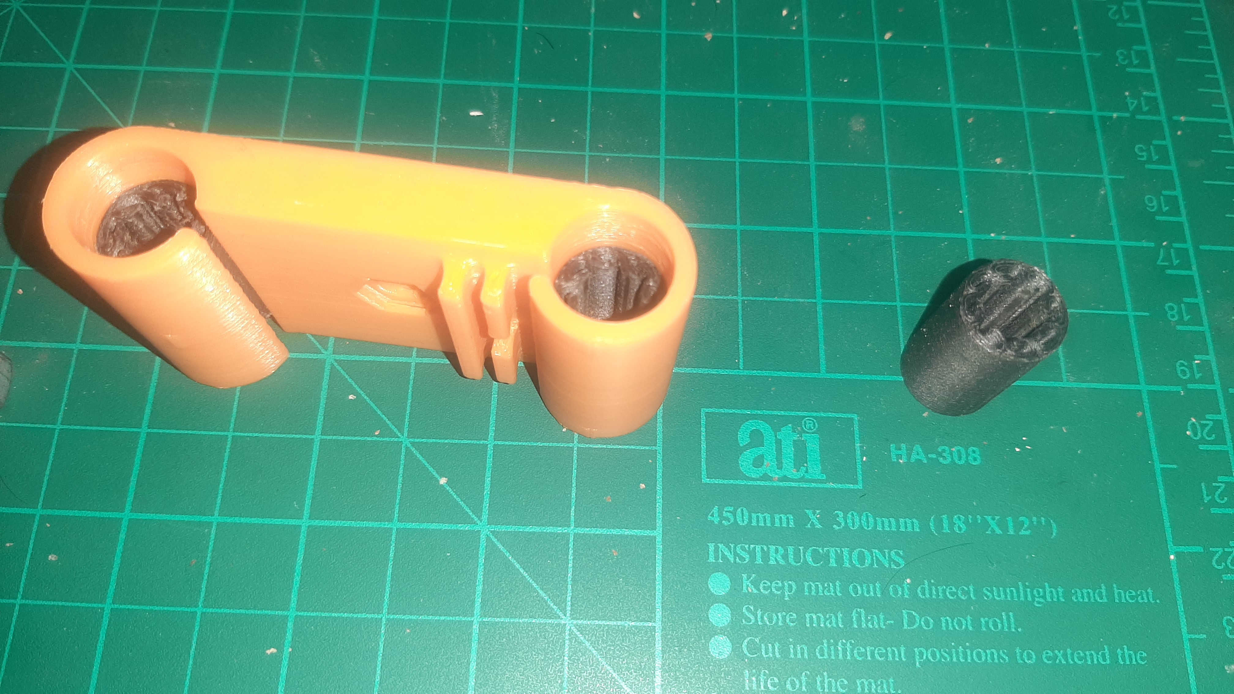
Because I didn’t have time and money to buy an LM8UU 8mm Linear Ball Bearing so I decided to print them along with the GT2 Gear
Because I didn’t have time and money to buy an LM8UU 8mm Linear Ball Bearing so I decided to print them along with the GT2 Gear.
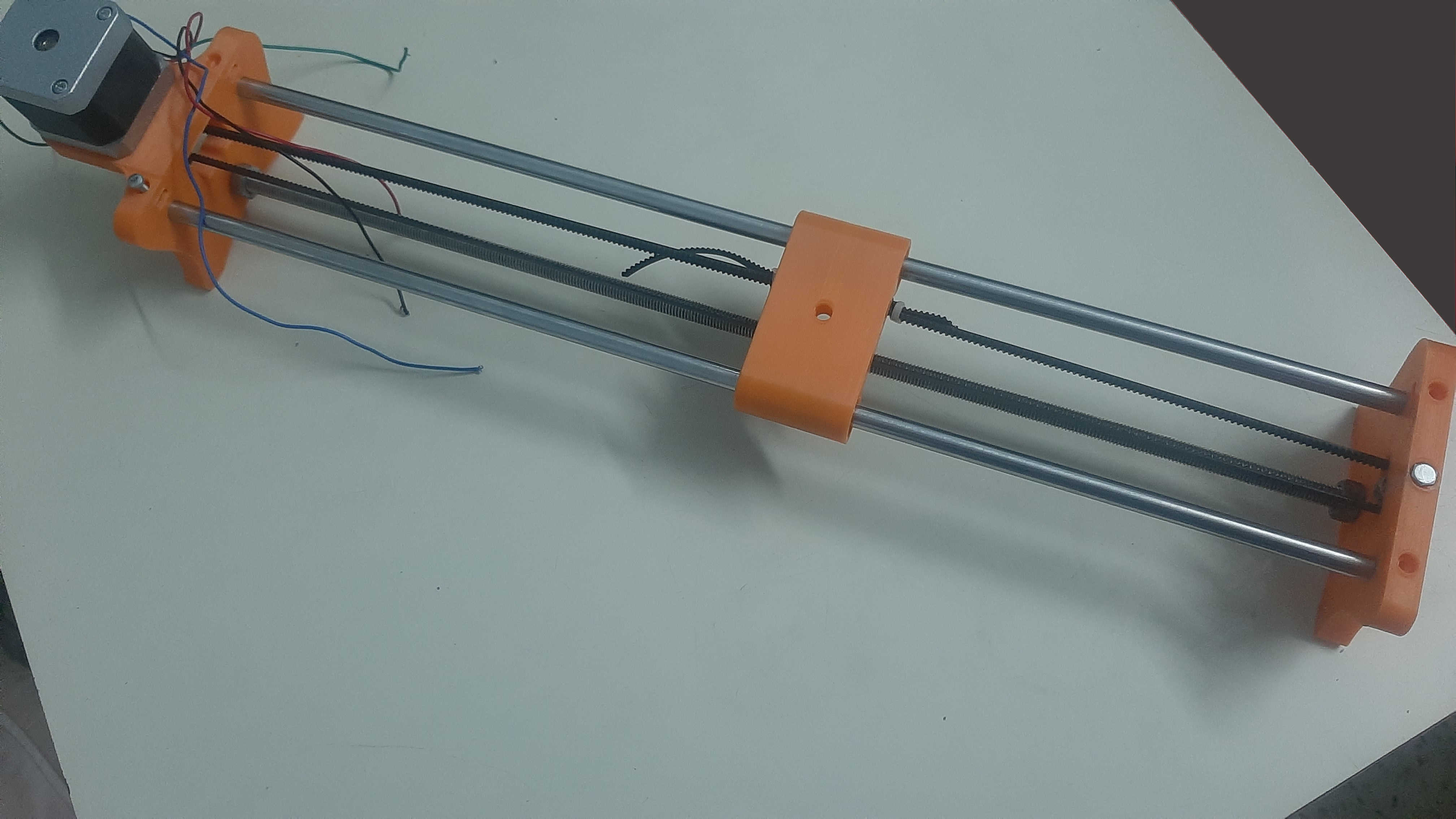
Assembling
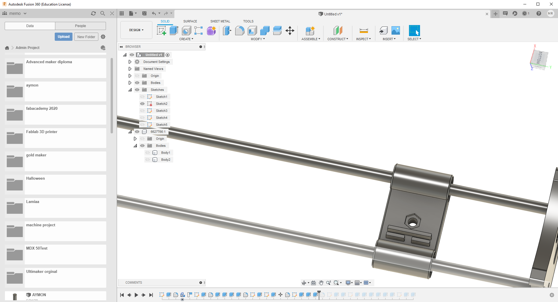
So the Assembling was very easy and everything fit perfectly and I didn’t need to use the fixation holes that I make for the smooth rod.
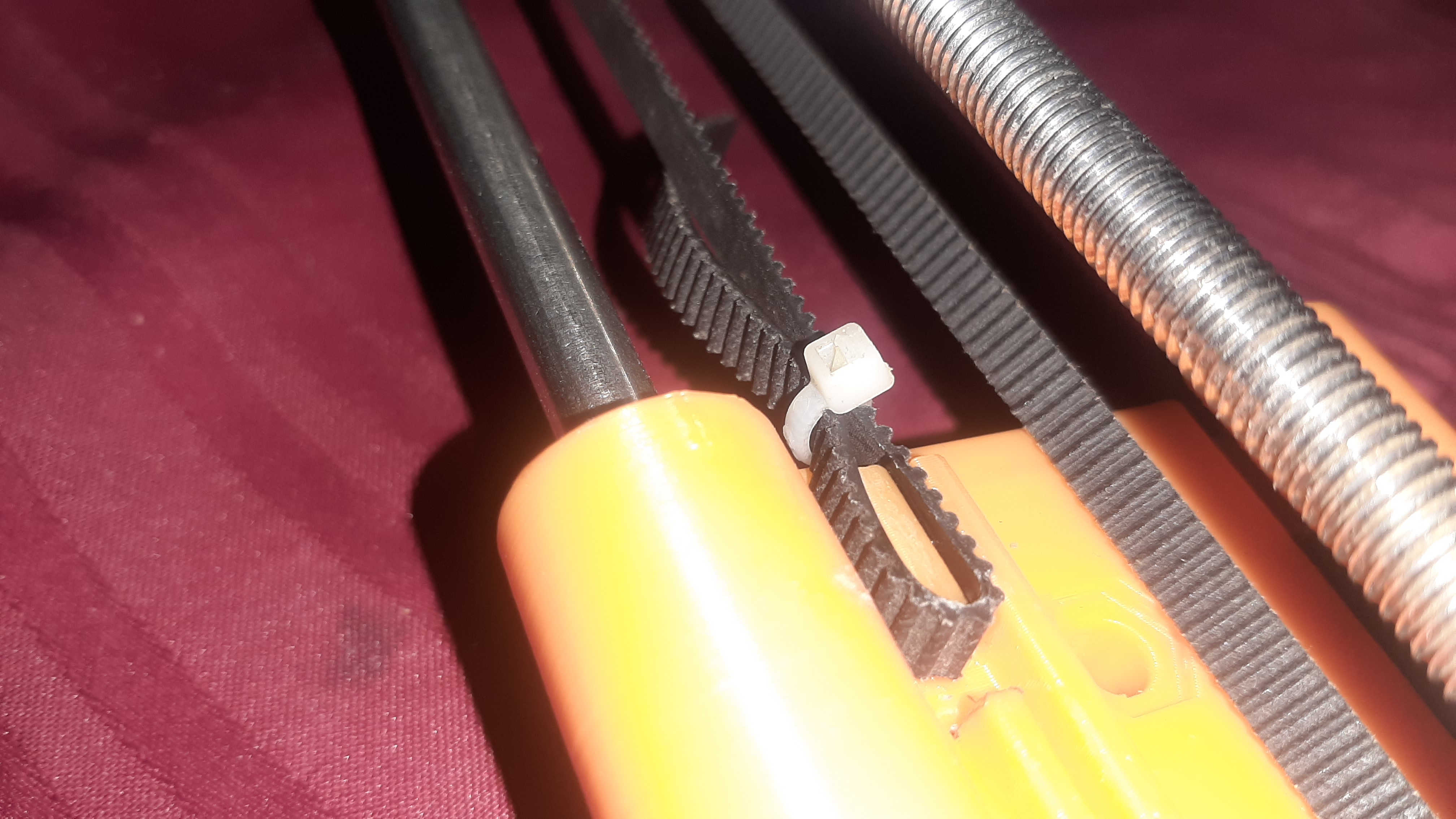
For the Linear Bearing, I had to smooth them first by hock the to the rod and move the bearing back and forth and after I assembled them they were a little bit tight on the rod but it works just fine, and I used a Cable tie fo fix the GT2 belt.
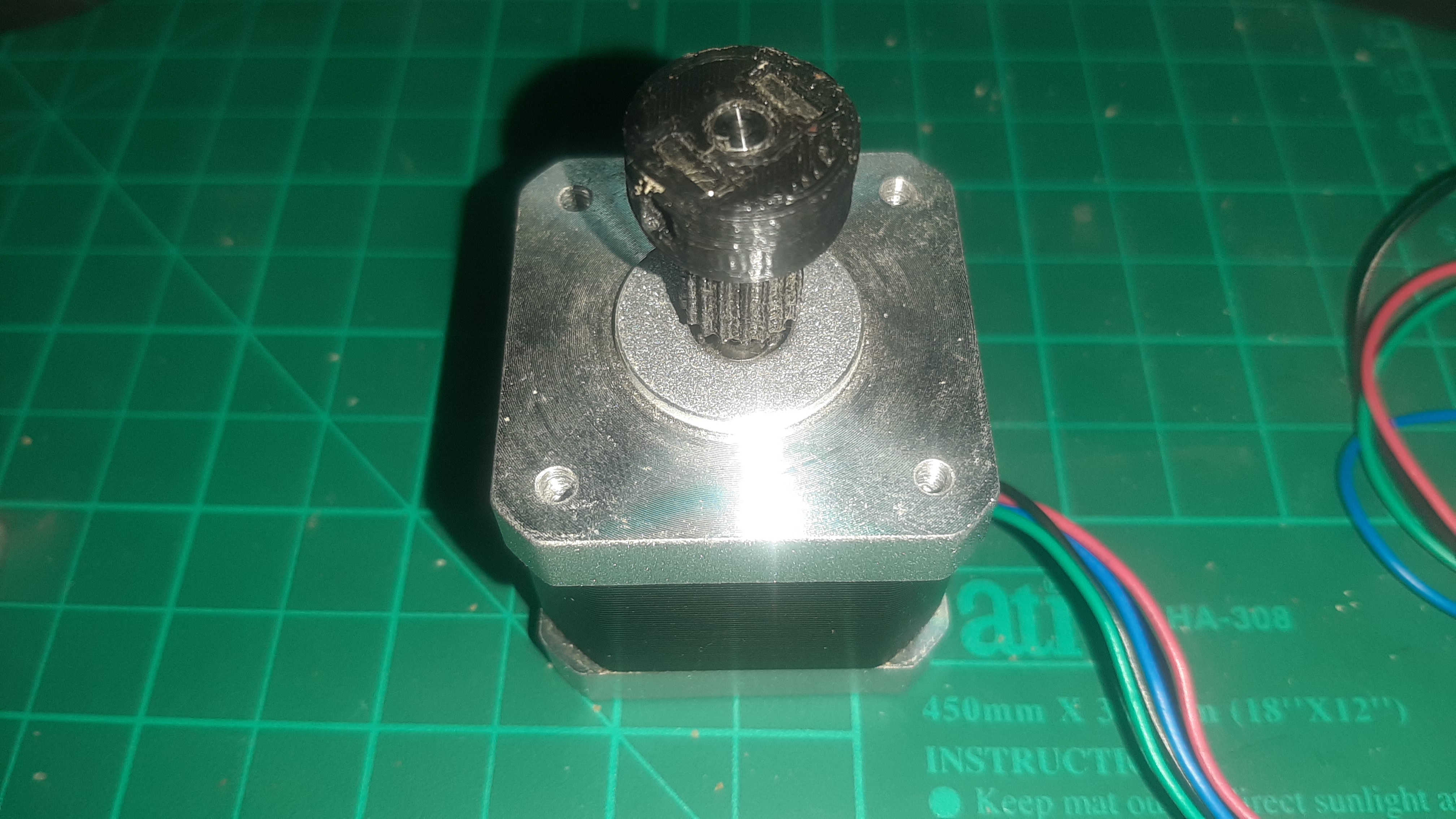
Last for the GT2 Gear I expected it to fail but Surprisingly It works Like the GT2 gear Yes I don't recommend To use it on something needs accuracy Like a 3d printer but it will work fine for me because I don't need accuracy, and I have some worries like how long it's going to work before the gears are completely destroyed, but this kind of question it will answer itself by time.
Assembling
In this section, my plan is to use CNC shield v3 with a4988 driver board but the bord didn’t work so after multiple tests I found the safety fuse was blown, I couldn't fix the problem I tried to connect a4988 directly to the breadboard as this diagram shows.
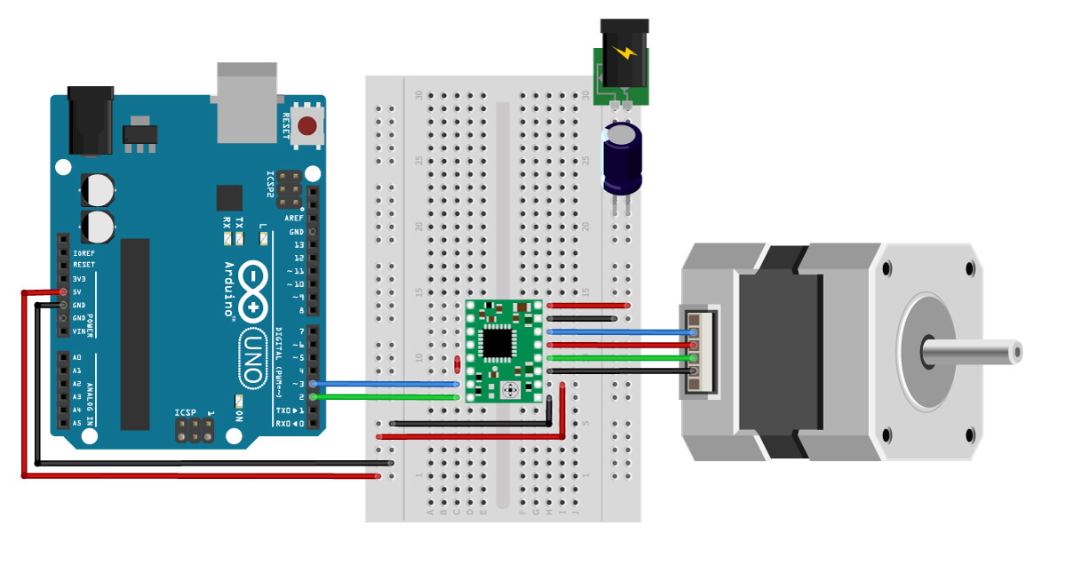
But I didn’t have any jumpers so I used internet solid wire cable but it didn't work I used the multimeter to check the voltage everything seems legit but it didn’t work either the hardware was a total failure for me.
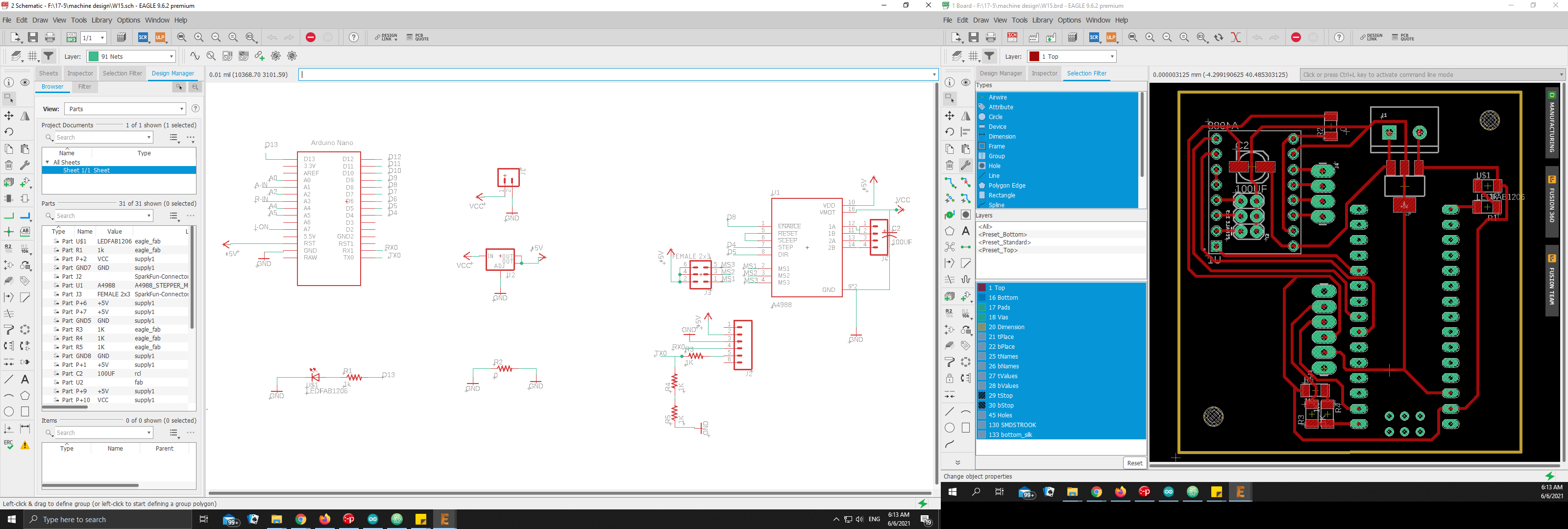
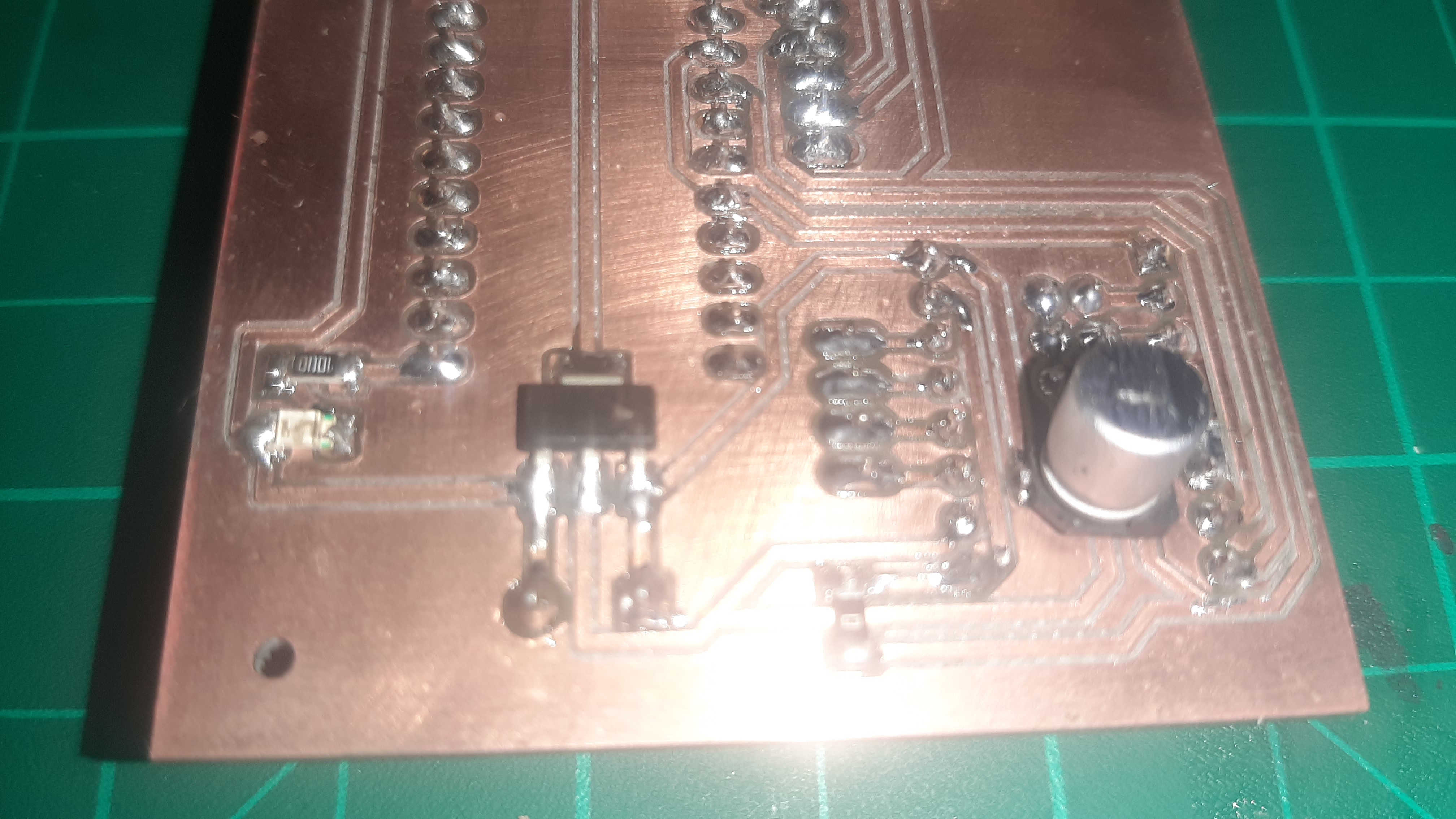
I started with my own version for the driver using Arduino nano with a4988, PS - I flipped all the bottom components so I can solder them easily at the bottom surface.
After I design and soldering the pcb it didn't work X" D, after some debugging I discovered that the serial froze I can send messages but without any response from the microcontroller and it works fine when I powered it separately using the USB.
After a lot of debugging, I accidentally damaged the voltage regulator in the circuit when I was using the multimeter to try to debug the problem, at this point I decided to use my DIY 3d printer Arduino mega 2560 with ramps shield to drive my camera slider, Desperate times calls for desperate measures "D
I was going to use Grbl firmware to control the camera slider but The Arduino mega already have marlin firmware so I decided to continue working with marlin firmware
what is grbl firmware and what is the difference between marlin firmware ?
GRBL is a firmware for arduino boards(uno,nano,Duemillanove) that controls stepper motors and spindles/lasers. GRBL uses gcode as input and outputs signals via the arduino pins.
Marlin is an open source firmware for the RepRap family of replicating rapid prototypers — popularly known as “3D printers.” It was derived from Sprinter and grbl, and became a standalone open source project, mostly use for controlling 3d printer.
in my case I just need to drive one axies so any of thim will work any way.
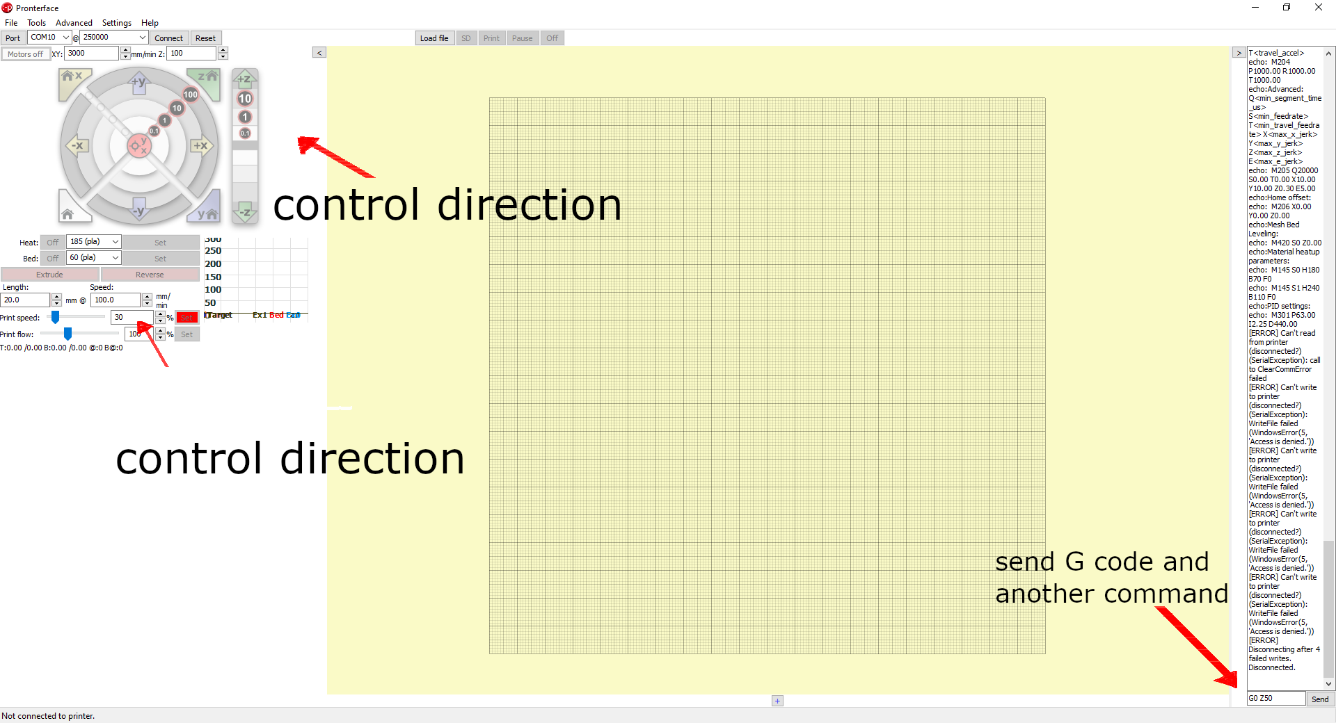
now for the most important question, how I'm going to control the camera slides movement, and It heat me I was using program called "pronterface" control any axies of my 3d printer and to debug if it was having any problem.
In pronterface I can control one axis I can control direction and speed, and I think that's the only two function that I need right now oh and last move the slider to a specific position..
After I connected my slider motor to the Z axes, I will give it a try to see If it will work or not spoiler alert It will work ْ"]
So yes I can move it really slow now I will hook my phone and try to take a shot with the slider, and this is the final result.