Embedded Networking and Communications
-
Group assignment:
- Send a message between two projects
-
Individual assignment:
- design, build and connect wired or wireless node(s) with network or bus addresses
Group assignment.
Individual assignment
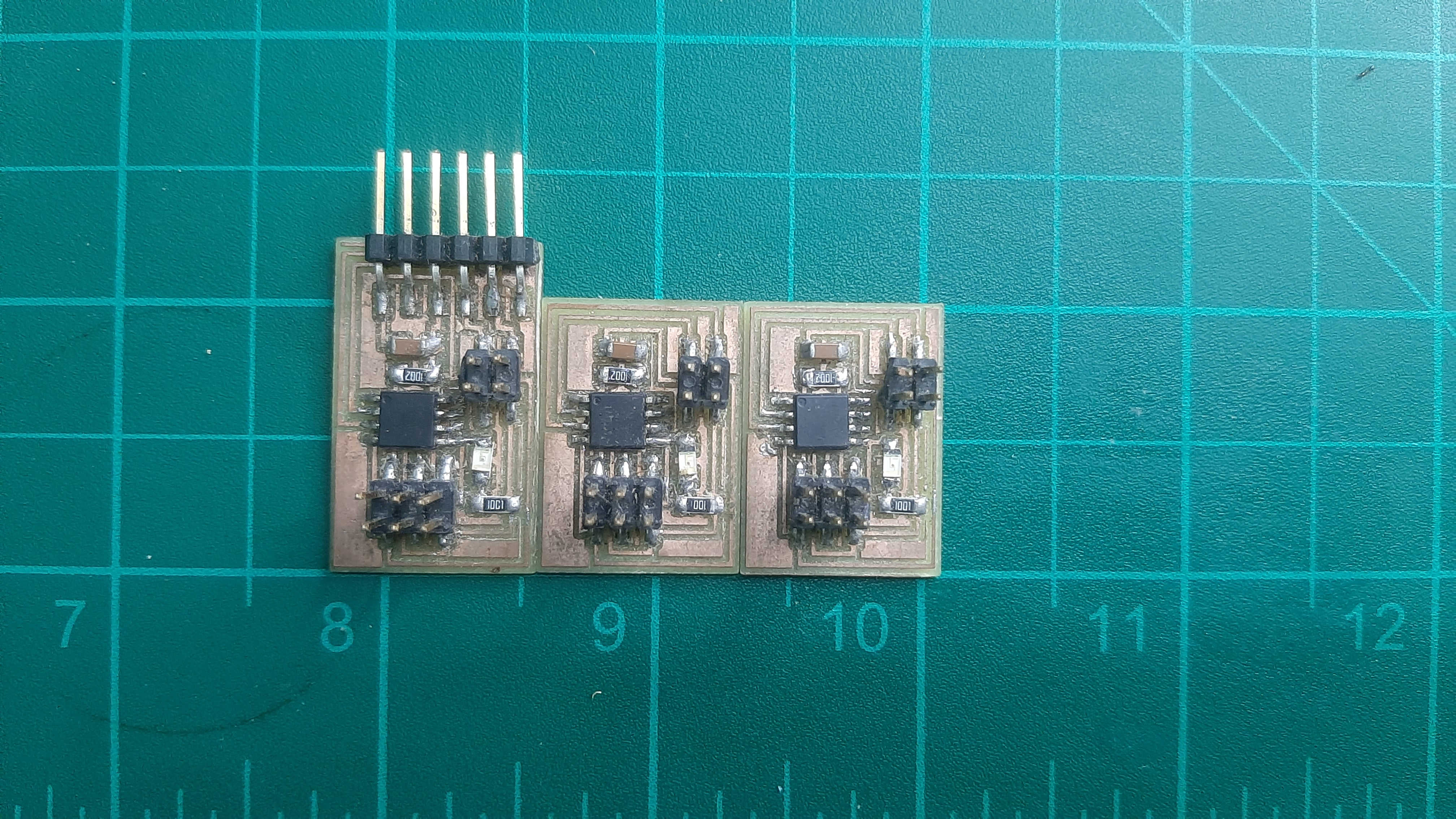
for this week I decided to remake professor Neil example because it's my first time using the communication method to understand the example and the next step is to make my own design.
I start, by downloading the pcb design first with the main PCB next PCB was the node, after milling, cutting, and soldering the PCB.
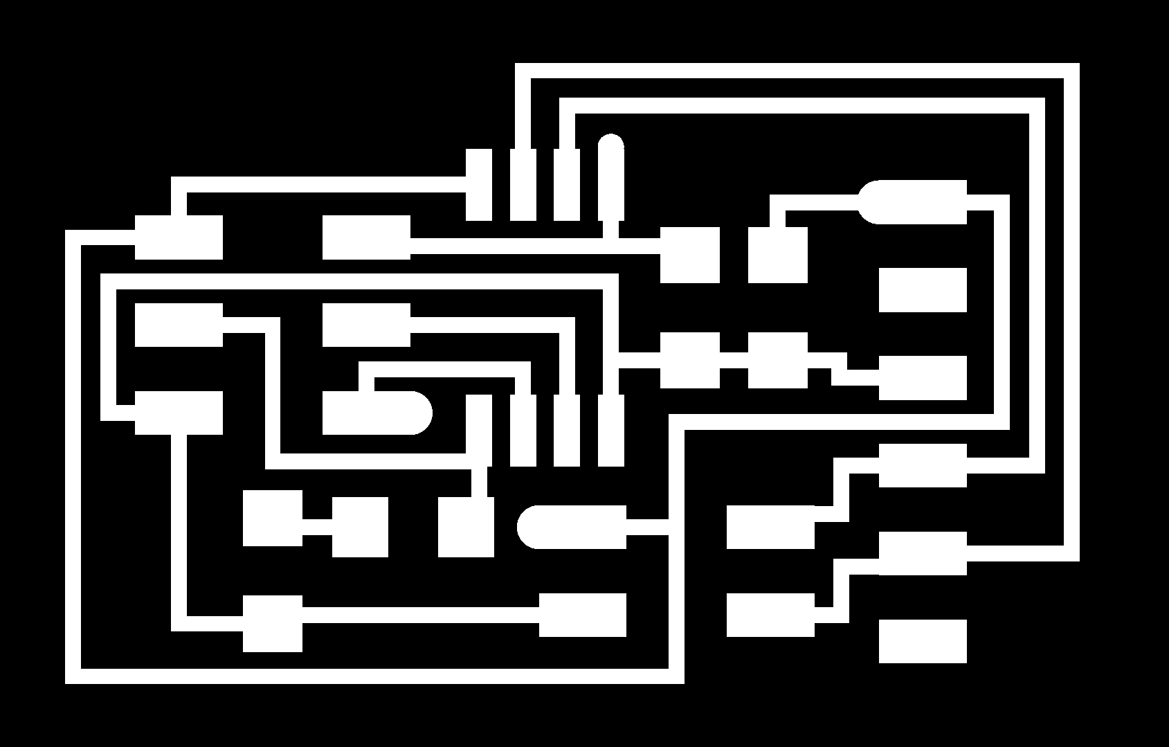
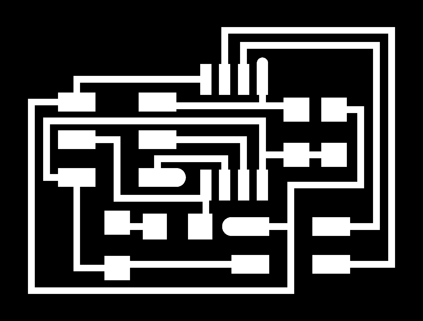
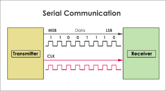
I know this PCB's use Serial Communication to communicate so I start reading about this method, and I found this great article to explain how Serial Communication works."The article"
But for short serial communication is the process of sending data one bit at a time, sequentially, over a communication channel or computer bus. This is in contrast to parallel communication, where several bits are sent as a whole, on a link with several parallel channels.
Next for the code, I started with reading the code and after implementing the example code it works just fine but most of the time I couldn't recognize the led flashing, so I decided to make a small change in the code to keep the led on and change with the node changes.
so what I make is basically I add a function to change the state of the led to on every time you call the node number and change with node chinging.

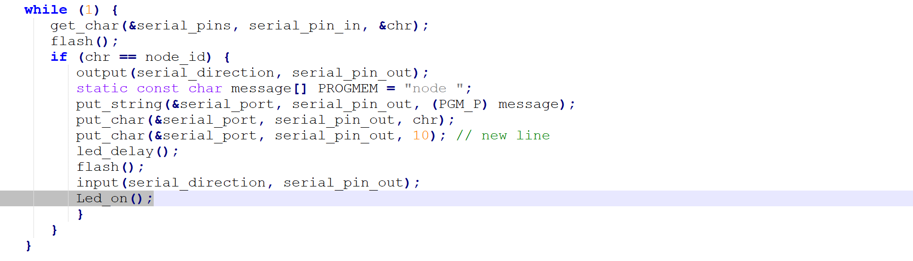
so what I did is basically I to change the last state of the "led_pin" function by using bitwise operators XOR, next I recall the function in "void flash()"
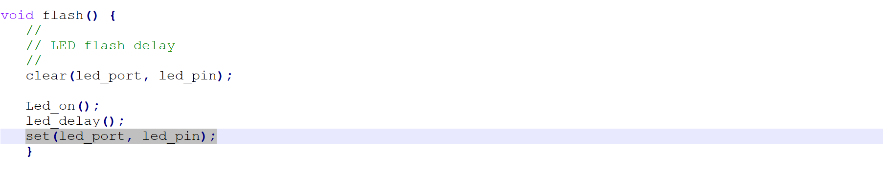
last I recall it at the end of the main while loop.
Note.
you need to change the node number, so you have a special number for every node you have.

After uploading the code I will use Arduino "serial monitor" to communicate with the nods, to do that you have to select ports from tools and select your "FTDI" port, last to set the baud rate to "9600" then we good to go.
So I used in this assignment two Protocols I2c in the assignment and UART in the group assignment and I would like to expand the Advantages and Disadvantages to Using I2C vs UART
UART
UART stands for Universal Asynchronous Receiver and Transmitter, UART can perform only asynchronous serial communication.
Asynchronous mode, this protocol makes use of only two wires i.e. Rx and TX. Since no clock is needed here, both the devices have to make use of their independent internal clocks to work. Yet there is a term called baud rate which helps these devices to remain in sync by fixing the speed of data exchange. Baud rate refers to the number of data bits transmitted per second, so both devices should work on the same baud rate in order to maintain their proper functioning.
Advantages:
1. Provides both synchronous as well as asynchronous serial communication
2. Availability of various baud rates making it suitable for wide applications and devices
3. One of the easiest form of serial communication
Disadvantages:
1. Can connect only two devices at a time
I2C
Another very useful synchronous serial communication protocol is I2C or Inter-Integrated Circuit protocol, I2C uses only two wires for the entire process, maybe that’s why it is also known as Two Wire Interface (TWI) protocol. These two wires are SDA (Serial Data) and SCL (Serial Clock). I2C protocol can support multiple slave devices.
Advantages:
1. Multiple masters and multiple slaves can be interfaced together
2. Only two wires are required for this communication
Disadvantages:
1. It is slower as compared to other Protocols because a lot of framing work is done within this protocol.