Input Devices
INDIVIDUAL ASSIGNMENT
So my objective for this week
- Try to make my magnetic field circuit successfully.
- Program the Cricut and run the python script .
- Make something creative .
So I didn’t know how I’m going to start this week after the pandemic and the stress at work so I decided at first to make a simple thing
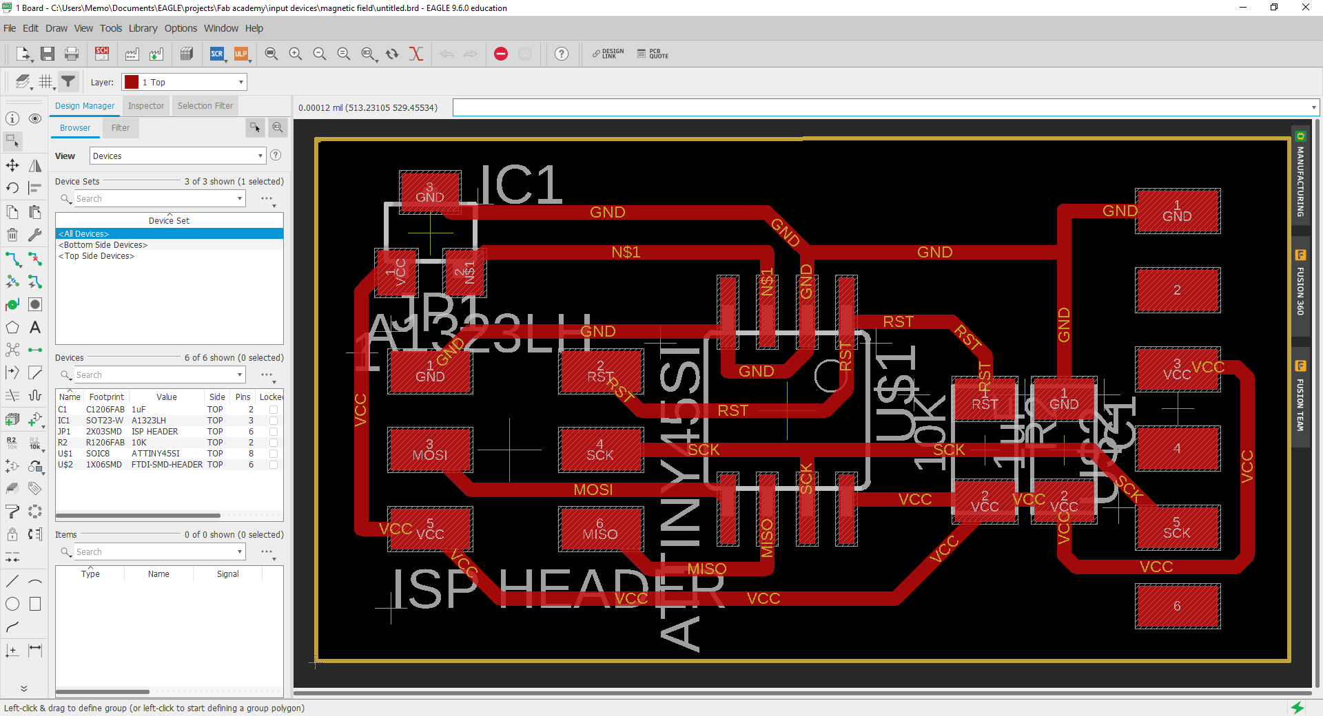
I was interested in the hall effect sensor so simple I said to my self, ok that’s it I will make the hall effect sensor so I start as always with eagle to draw my schematics and the layout.
And it was easy when I found the example PCB board
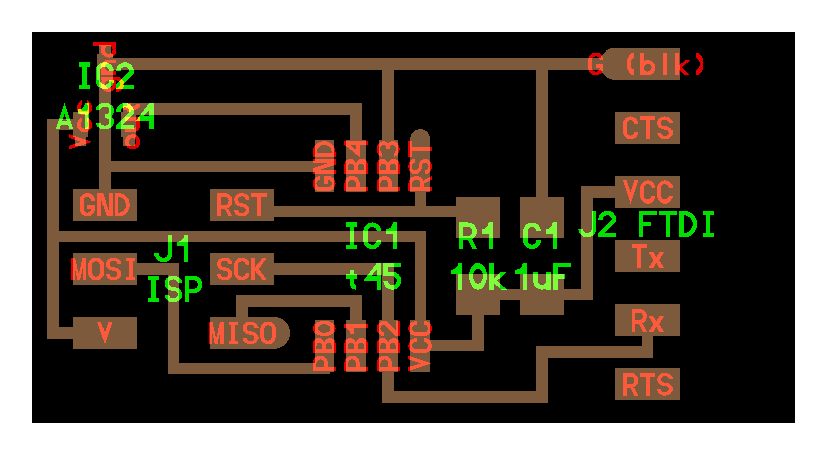
After redrawing the PCB I mill and solder the PCB so to not repeat myself so I repeated the mailing and soldering steps from Electronics Production week.
Programing the circuit.
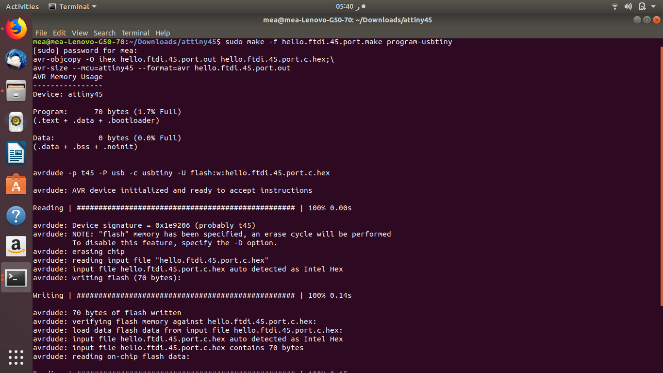
After hoking up the isp programmer to the circuit & downloading the c and make files, Now we will type.
sudo make -f hello.mag.45.make program-usbtiny"
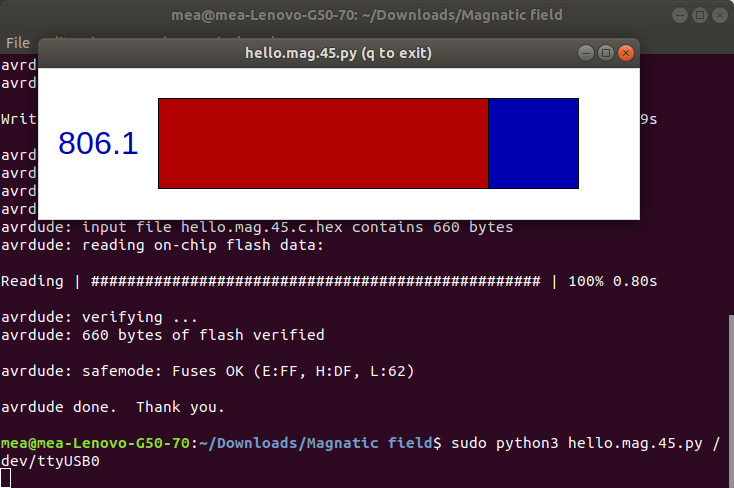
And now everything looks good it’s time to run python code, to run the py code I need to type.
Sudo Python hello.mag.45.py /dev/ttyUSB0
But it didn’t work and I saw this error.
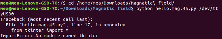
So I start with searching first I found that I need to make the “tkinter” statement in py code lowercase to work, but when I found that the in the py file has tkinter is lowercase and back to searching again X””D
So I found out it was a missing tool or library so I need to install it by typing.
sudo apt-get install python-tk
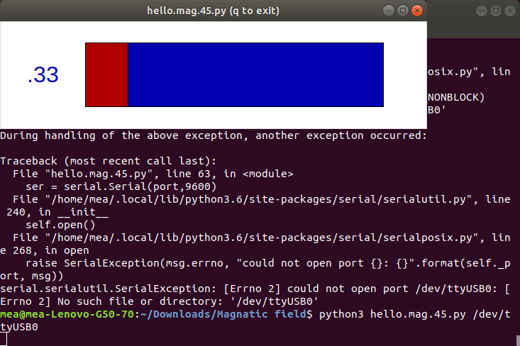
And it didn’t work either with the same error so after a lot of searching that the solution was in using python 3, And it work I think the error has changed and now the windows cannot find ttyUSB0 X”D
$ python term.py /dev/ttyUSB0 115200
Traceback (most recent call last):
File "term.py", line 92, in
ser = serial.Serial(port,speed)
File "/usr/lib/python2.7/dist-packages/serial/serialutil.py", line 240, in __init__
self.open()
File "/usr/lib/python2.7/dist-packages/serial/serialposix.py", line 268, in open
raise SerialException(msg.errno, "could not open port {}: {}".format(self._port, msg))
serial.serialutil.SerialException: [Errno 13] could not open port /dev/ttyUSB0: [Errno 13] Permission denied: '/dev/ttyUSB0'
But I try to restart my laptop and it finally worked
But I didn’t read any data so at this moment I was thinking this project was cursed at this point, so I will start the debugging process so I start with the oscilloscope so I hocked the ground with PCB GND and probe with the “RX” pin so I did get voltage it was 3.6 with a lot of noise without any changes from the sensor when I close it to the magnet
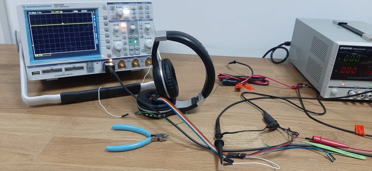
So what I have in my case was programmable ATtiny 45 and no output from the RX and everything powered of course it will be the sensor problem but Kamel said to me hmm maybe not, so as a final test I opened the sensor datasheet so I see ho it operate and it came to me, I can power the PCB with the FTDI and try to see if I can get readings directly from the output sensor pin.
And so I don’t have access to the oscilloscope at this time so I used instead my old digital Multimeter so I was doing that as a last prove that the sensor doesn’t work but what I didn’t expect that I get readings from the sensor.
And now I didn’t know which part has the problem I trayed to reprogram the microcontroller and it programmed successfully and same, so how it comes that I don’t get reading’s from the RX and at this point I have wasted a lot of time and effort and I was expecting to try more than one input.
Make something creative.
Now after a lot of thinking and searching on the input circuit I found out all the circuits have something common they all use the VCC, GND, and pin” PB4 and PB3” and also I can reprogram the microcontroller more than 10000 times.
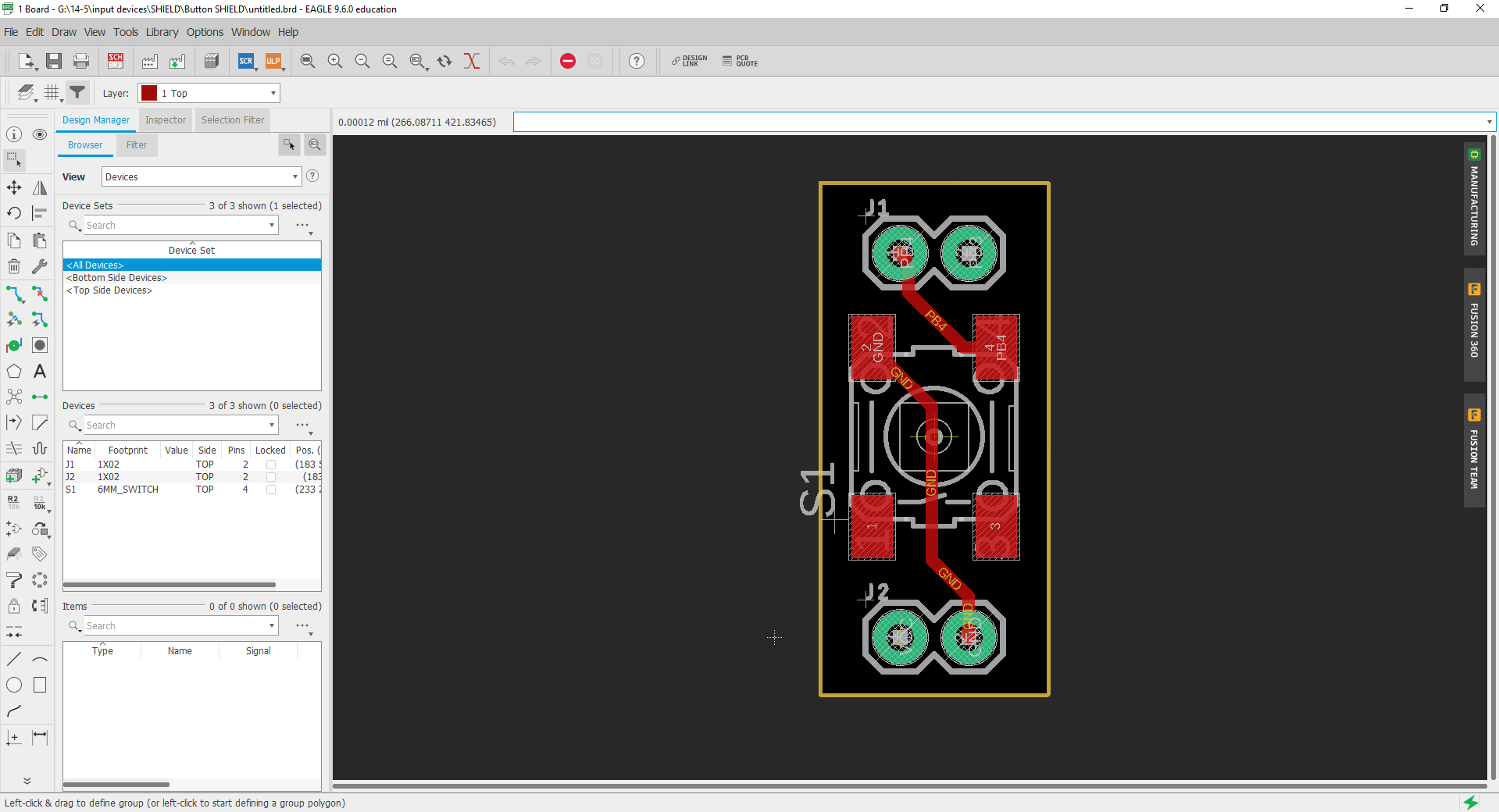
So what I don’t make the PCB have some sort of shield so I don’t waste a lot of component’s at my trails and I can make something like a small input test bench so if I have a project I can finger out easily witch sensor will fit perfectly with my project.
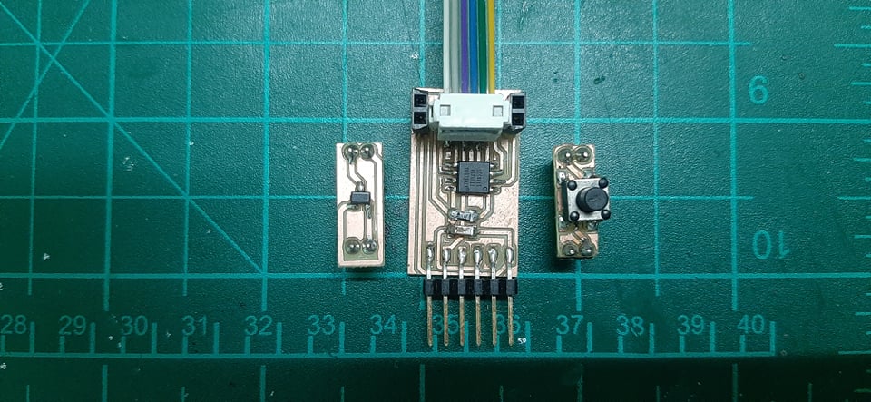
So I started with the most basic input the “Push-button” as I said I wasted a lot of time without any result so I need to test with the bare minimum of components and get a result, And I started with my main PCB.
So after drawing the PCB I ended up with this shape.
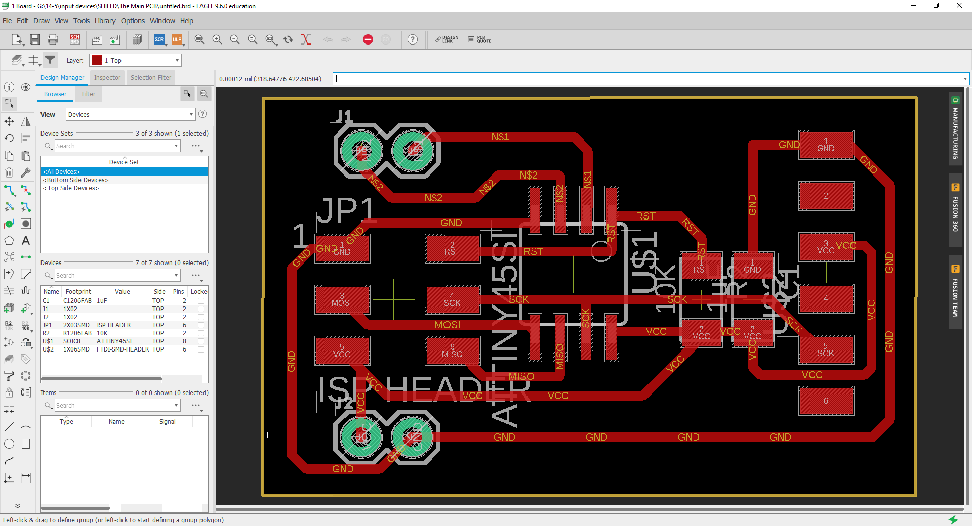
So for making the sheld to Avoid making errors so I just coped the main PCB and I just deleted and adjust the components to make the sheld without moving the pin header so everything can fit perfectly, Now after I finished my first it’s time to cut and test my circuit, it’s time for milling and soldering.
Now for programing the PCB and test our first sheld so after downloading the c & making files and FUSE them with this command.
sudo make -f hello.button.45.make program-usbtiny"
So for connecting the FTDI with the terminal or to be specific I need to read from the terminal the data that has been sent from the FTDI, So to do that first I will need to install a tool called “pyserial” this tool will handle the communication with the FTDI.
So to install the tool, run this command.
Sudo apt-get install python-pip
pip install pyserial
So now I’m ready to connect everything and test the shield, now I will run the tool by typing.
python -m serial.tools.miniterm /dev/ttyUSB0 9600
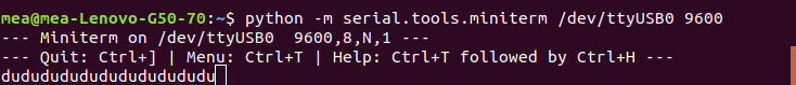
Finally, I have an output so the next thing that came to my mind is to make a shield using Hall effect from the old circuit so I used the hot air to disorder the sensor from the PCB and added to the hall effect sensor shield and repeated the programming steps from before, and Surprise it worked I was very happy and sad because I didn’t have an answer for the way my first PCB doesn’t work.
So I will try to make more shields and try new inputs at the soon future but after I finish the late assignment’s X”D