Electronics Production
Electronics production
Group assignment:
- Characterize the design rules for your PCB production process: document feeds, speeds, plunge rate, depth of cut (traces and outline) and tooling.
- document your work (in a group or individually)
Individual Assignment:
- Make an in-circuit programmer by milling and stuffing the PCB, test it, then optionally try other PCB fabrication process.
My objectives for this week
- Learn how to use the milling machine
- To set up the program machine on my laptop
- Make and program the PCB
- Make my own version of the PCB
- Try to make a green mask with a milling machine
Group assignment.
First I will start with the group assignment so because we still don't have a group assignment website so I will add "Ahmad Saeed" group assignment documentation link ...
Individual assignment:
Electronics Production.
So this isn't the first time I use MDX-20 but professor Neil has mentioned a way to fix the PCB to the machine with two layers Paper Masking Tape and one layer of Double-Sided between them. It will make PCB cleaning easier for me and I will not use the sacrificial layer every time I need to change the PCB.
spoilers alert, it worked perfectly actually I was amazed by this simple trick it saves time and resources.
Moving one after I seat the new PCB on the machine now I have to generate the G-code, so I will use http://fabmodules.org/ but from the local server.
So to initiate the program first we need to open fab modules directory from the terminal.
mine was.
cd home/fablabegypt/mono\ fab/fabmodules/
Next is to run the program by typing.
npm start
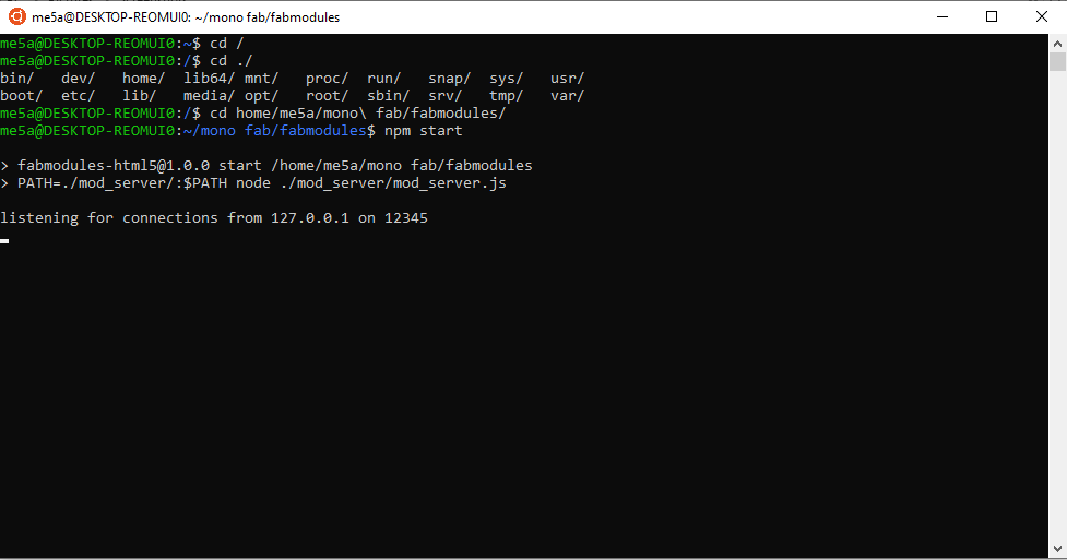
Now we have to go to the link shown in the terminal, normale it will be like http://127.0.0.1:12345/
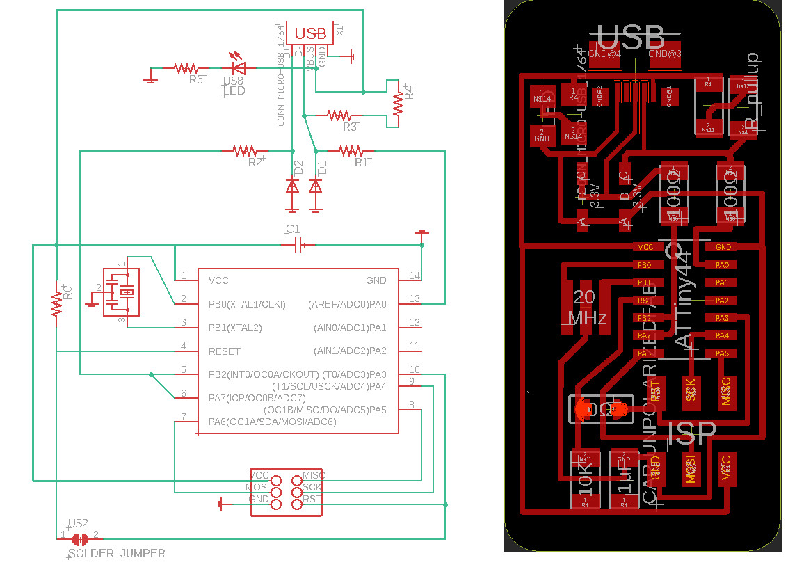
Next is to generate the ISP trace G-code from the ISP IMG.
input format > image (.png)
output format > Roland mill (.rml)
Process > PCB traces (1/64)
Now I will select the machine type “MDX-20” and the place I want to cut the PCB in, last numbers of offsets.
Ok for the place I but a new PCB on the machine so any place will do so you need to type you place coordinates fot the fab modules
x0 (mm):
y0 (mm):
z0 (mm):
And click “move to xy0 zjog”.
For the milling tools what I like to do is to close the Z to the PCB and lose the end mill screw and let the end mill touch the PCB and tighten the end mill screw again.
Now we are ready to calculate the track distance but before that about “ numbers of offsets”
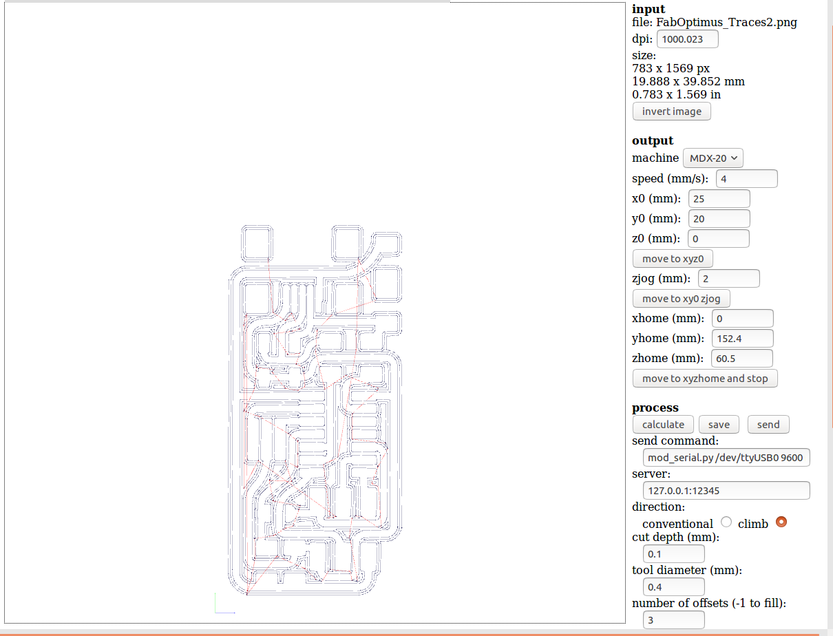
Note if we right -1 we will remove all the copper between the PCB except the tracks but I will leave it with 4 offsets to make it easier with soldering.
Last to cut our PCB outline.
we will do basically the same steps the only change is select in " Process > PCB traces (1/32) instead of (1/64)
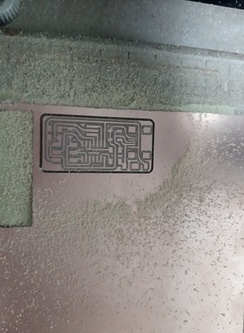
this is the final result.
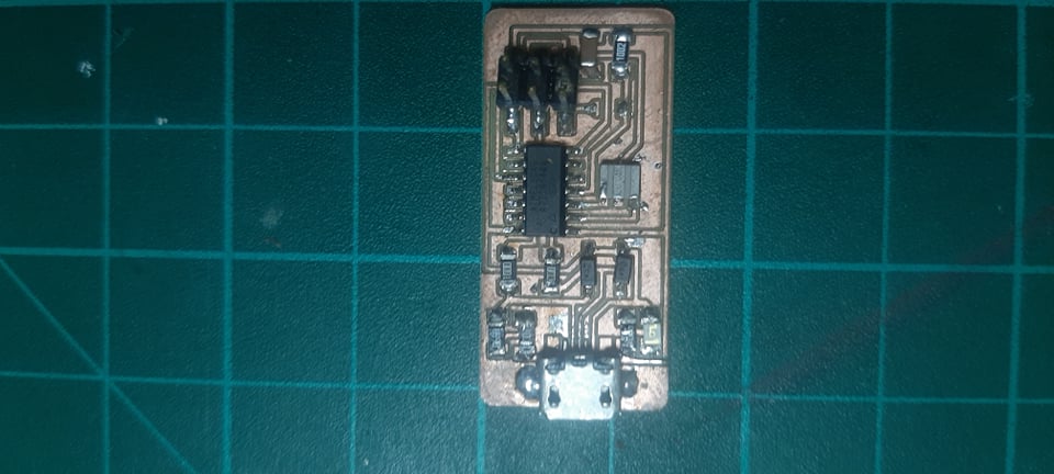
Soldering the ISP.
So I make two mistakes.
First, I didn’t check for the components that the instructor gave me so 1k ohm instead of 10k ohm.
Second, I didn’t prepare the place that I was soldering at so I ended up losing more components.
So Second time I used the double face tape to set the SMD components I found this way more easier for handling the components.
Programing the ISP
Really for the last two months, I have been bouncening from Linux to windows back and forth So I to install windows for cad and I tried to use Linux subsystem as a replacement from Linux it sounds great at first but not really I was having a problem with configuring any tube of USB and nothing.
So again I installed Linux distribution again.
So for programing the ISP I followed the Programming tutorial it was very useful
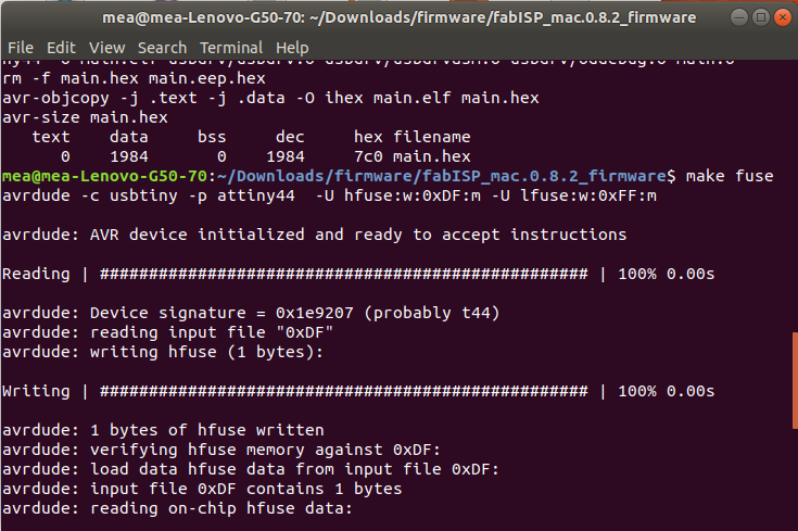
So I used Ahmed Ibrahim ISP to program mine but after following the guideline I get when i “make fuse” I get error 1
So at first, I tested the circuit for any short circuit but nothing, and by Ahmed help, I figured the error out
At first, I was thinking that the code can be fused without any modifications but the truck was to choose the programer type and remove the hash before attiny and rehash the other line.
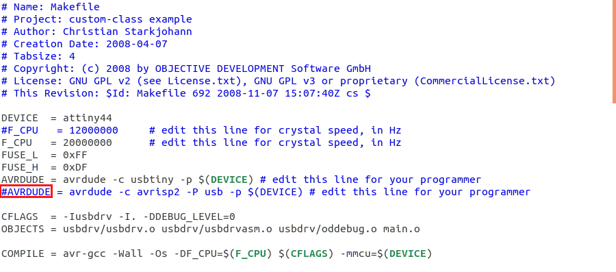
Now for the programming command.
sudo apt-get install flex byacc bison gcc libusb-dev avrdudesudo apt-get install gcc-avrsudo apt-get install avr-libcsudo apt-get install libc6-devcd ~/Desktopcd fabISP_mac.0.8.2_firmwaremake cleanmake hexmake fusemake program
Ali has mentioned a note at his tutorial that I have to remove the 0-ohm resistor so our board cannot be reprogrammed. For this, we could use either a jumper (0Ω resistor) that can be removed once the board has been programmed.
The last step is to cut the trace leading to the VCC pin on the 6-pin, So we don’t overdraw the current from the USB port.
Now let's test the "fab ISP" to see if the PC could recognize it.
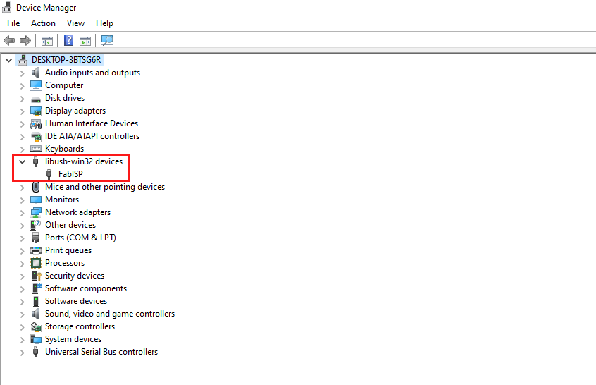
It's alive it's alive!!!
green mask.
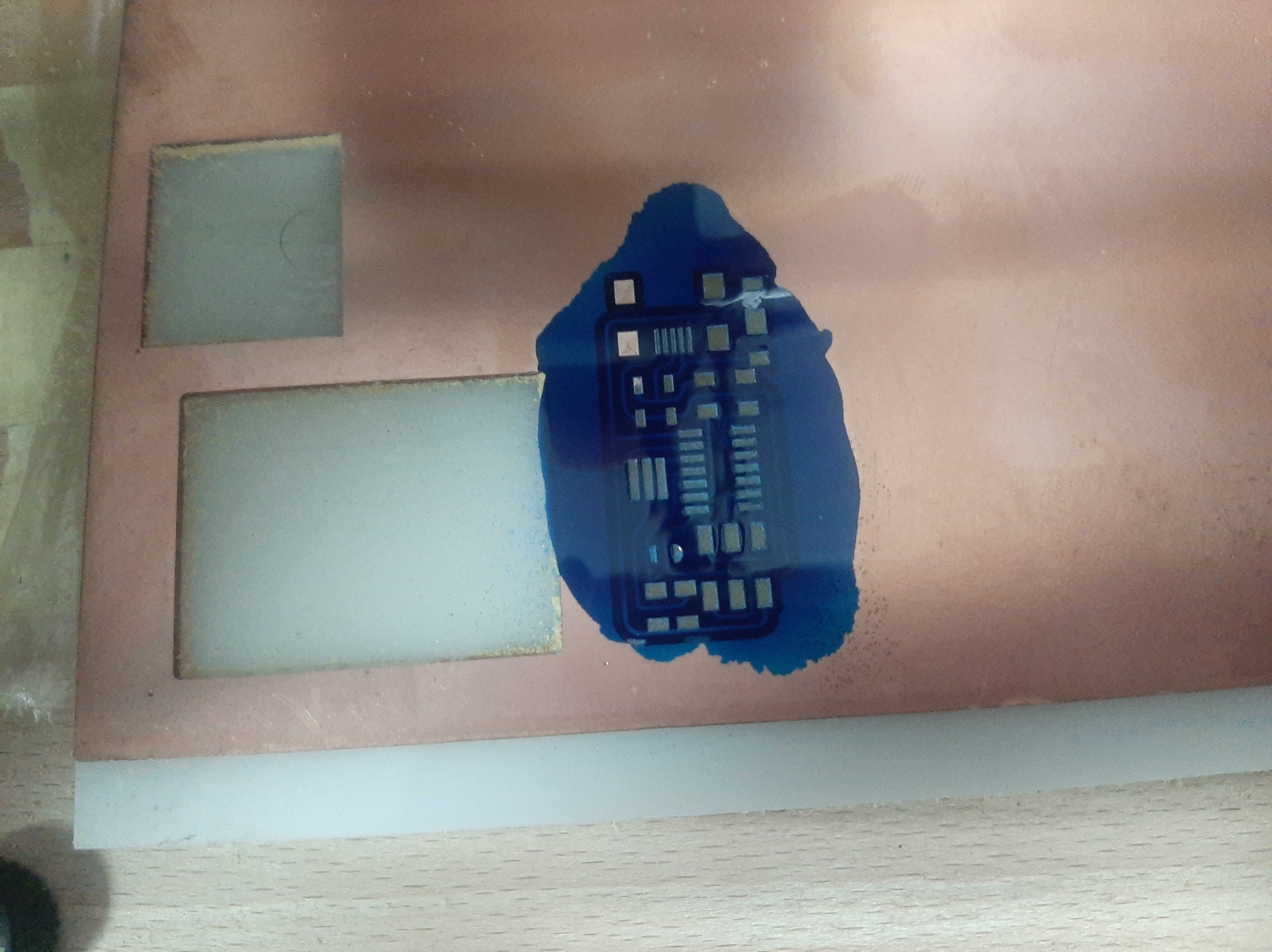
I saw a video of milling machine that etching the green mask with the endmill so I tried to do the same"D , now after mailing the man trace I didn't think about how to remove the PCB and add the green mask and how to but it back without changing the PCB origin, so it came to me the brilliant idea is to add the green mask and curing it inside the machine X"D
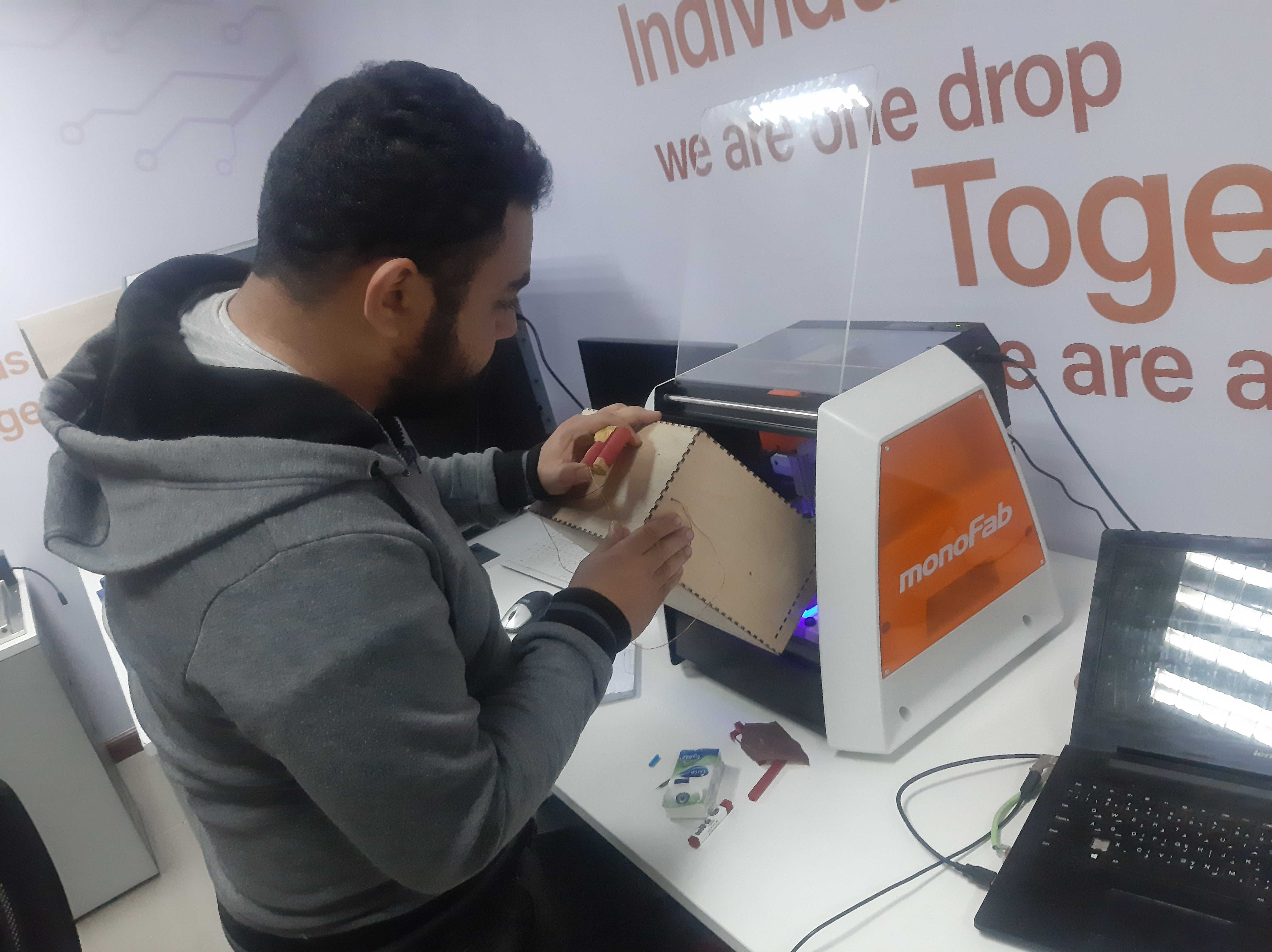
Ok to for testing if it will work or not, my first try was after adding the blue mask is to mill only the pads and recalculate the Z hight so to make the machine eatch only the green mask with 0.01 deeps but it failed and it round all the pads
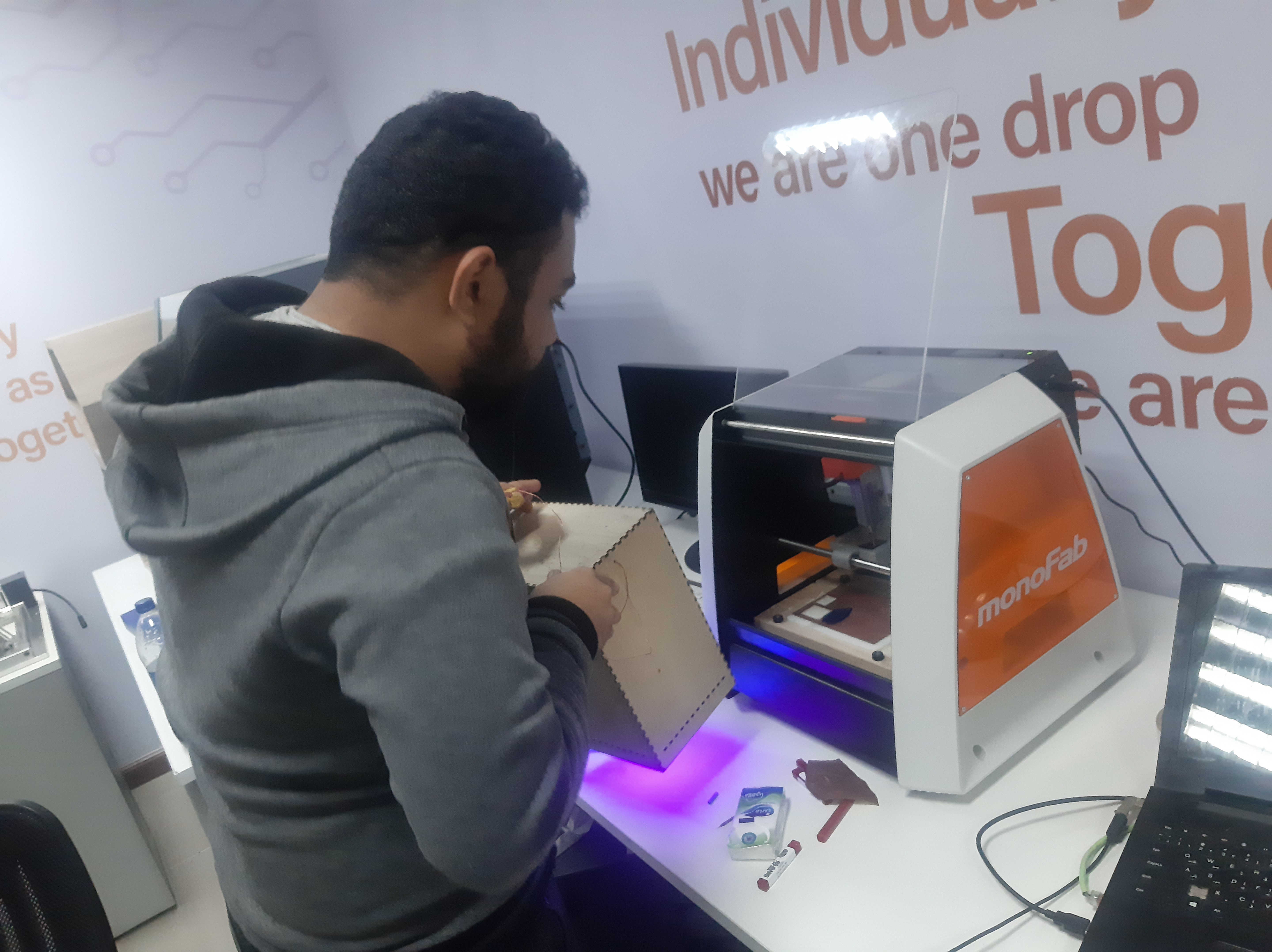
Next, try after milling the traces again and added the mask again is to mill on the surface of the PCB with 0 Z Deeps and this was the final result x"""D , only two pads have survived the milling prosses X"D , for my conclusion I think I need to surface the milling machine and try again but maybe in the final project PCB because I wasted a lot of time at my trails,
pc there is an easier way is to print the pads in black on transparent paper and cure it with UV light it will cure the PCB except for the black pads and you can clean it with alcohol to remove the uncured green mask, I didn't try this method yet but a friend of mine told me about it so I'm sure I will make my final PCB with a green mask finish
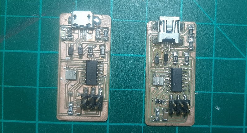
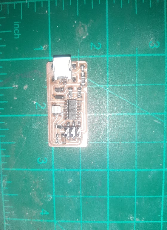
Making my own version.
So there were two things that were bugging me about the ISP.
There was no indicator that the isp works or powered on and if he is programming or not.
Why does the programmer use “USB Mini a” ! I'm having a hard time finding his cable and I ended with borrowing from a friend so I will change the USB mini with USB micro B.
So I downloaded Ali fab isp files and make my own version so what I did as a start is to add the micro USB and next to add a led as an indicator for the PCB to make it has power.
now after rebiting, the hole proses from before now it's time to solder the PCB the USB micro footprint at the PCB layout was a little bit bigger from the micro USB that I found at the lab inventory and second thing was the micro USB wasn't shielded like the mini USB and the problem was the there is a VCC line under the USB micro and the outer body for the micro USB was shorted with the ground, so what I did is to but a small piece of paper tape under the micro USB to isolate the track it was a little bit tricky to solder but I manage to do it,and it looks lovely X"""D .
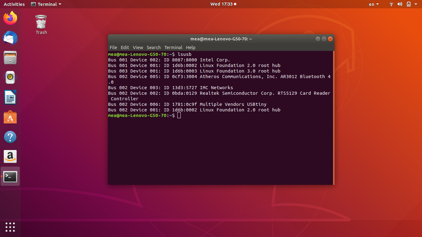
so to make sure that fab isp is work
open terminal and type this command "lsusb" will show all the connected USBs on your device and one of them should be related to your FabISP as shown below.