Final Project
I had a great and sad experience with my first final project I was attending to make a prosthetic hand but due to coronavirus and a lot of other problems I couldn't get to finish it but I love to share The result with the community "Link".
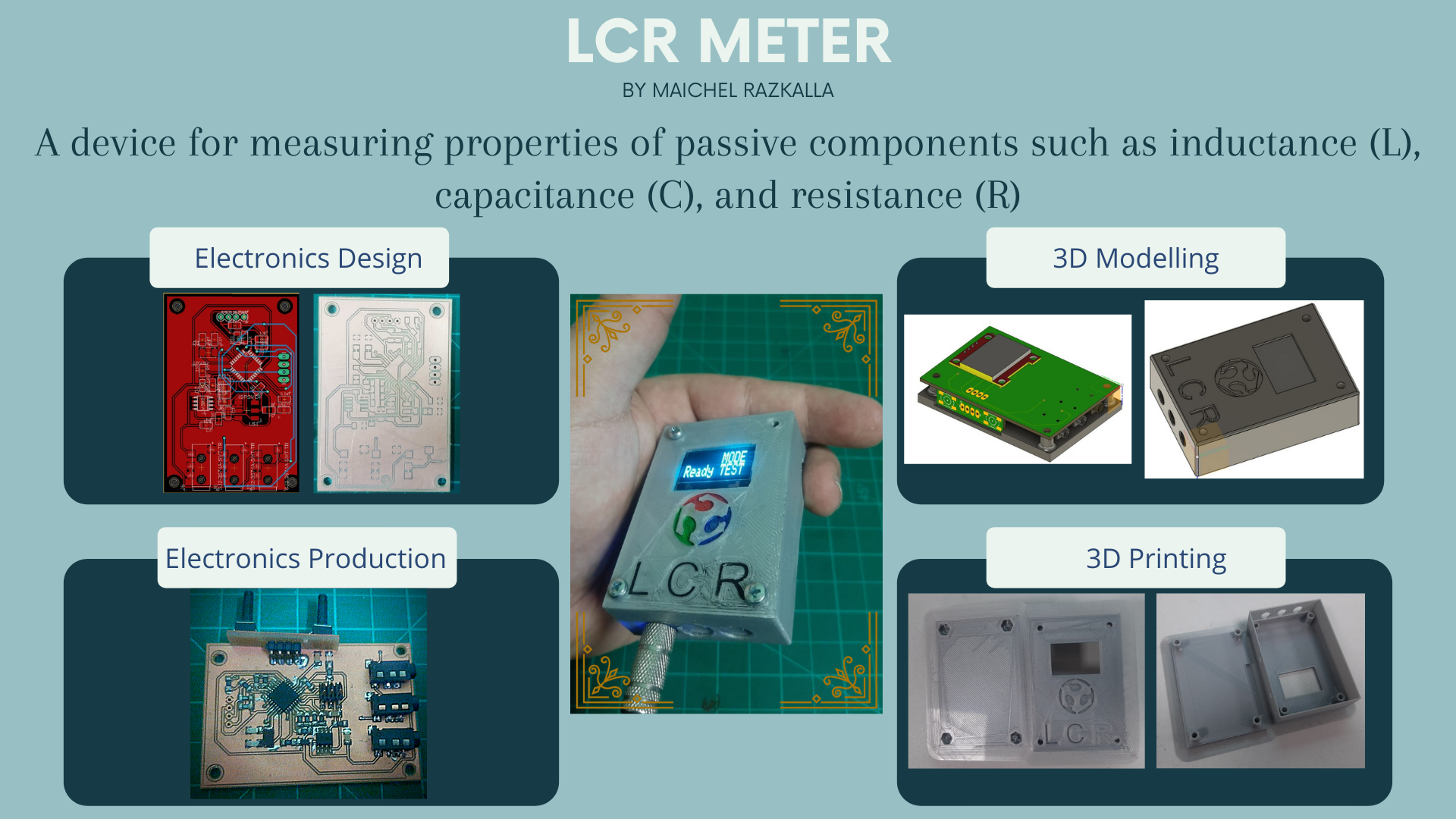
In this project, I'm attending to make an LCR meter.
What is an LCR meter?
LCR meters are measuring instruments that measure a physical property known as inductance (L), capacitance (C), and resistance (R).
I started doing my research to see if there are any similar projects. I couldn’t find any at Fab Academy archive, but I found many DIY projects with similar concepts when I searched on google.
In the designing phase, I have to be clear about what I would like to make and include like design shape and process.
- I would like to be small enough, pocket-size maybe
- I would like to add a small tweezer to test SMD components
- It would be very nice If it has only 2 ends to test all the components like the small LCR tweezers meter, but I don't know if I’ll be able to make that X"D
Because I have found many methods for testing components, Now I have to find the method that I'm going To use and the concept of measuring behind it.
Research and development stage
How The LCR work?
Resistance
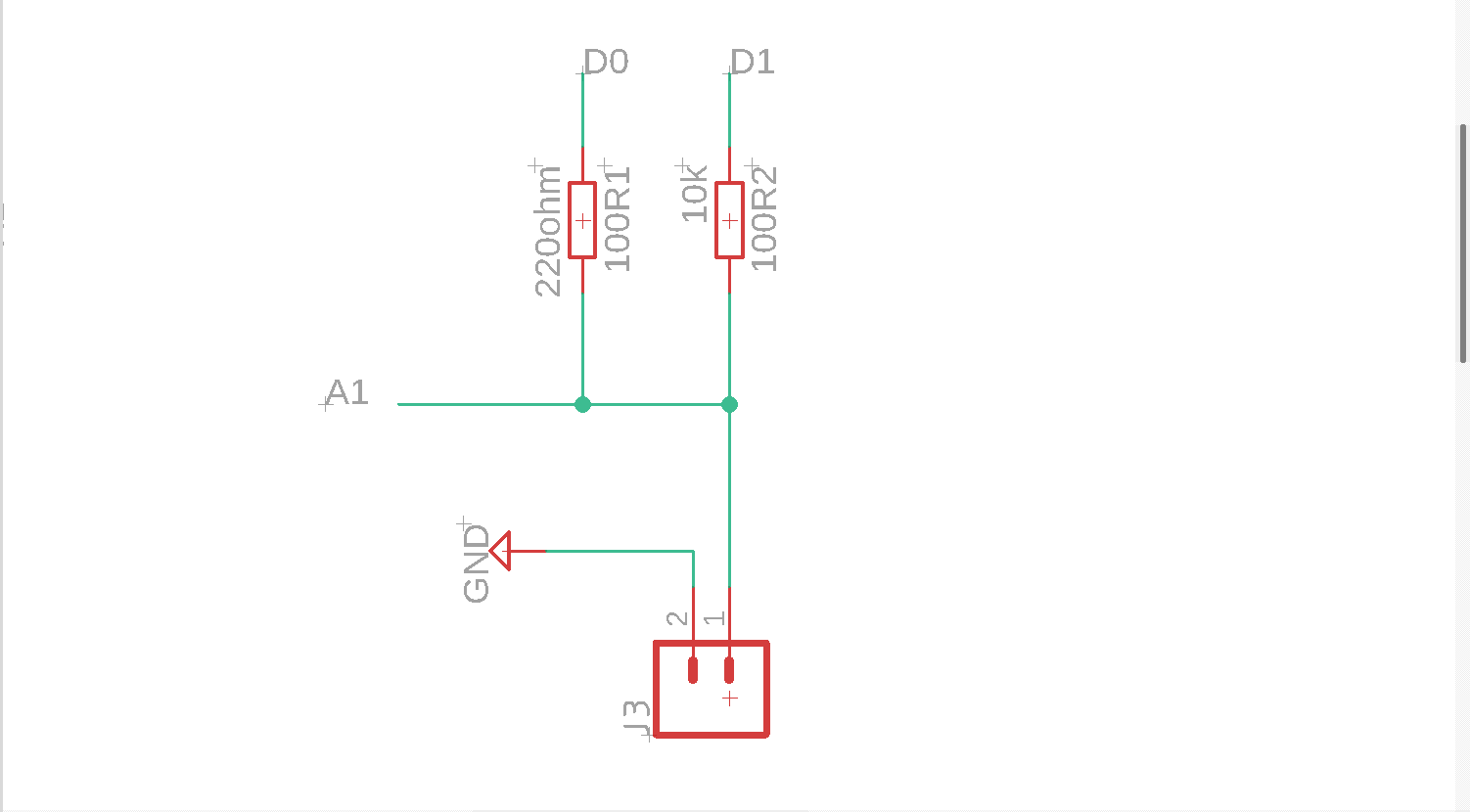
I will start with resistance because it's the easiest of them resistance meter is simple all you need is a microcontroller, the resistor you want to measure, and another resistor with a known value and predetermined voltage. I can calculate theoretically the missing resistor value using Ohm Law.
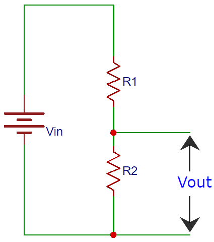
A voltage divider is made of two Resistances (R1 and R2) in series. The output voltage in the middle point, Using this formula "Vout = Vin * R2 / (R1 + R2 )"
From the above equation, we can deduce the value of R2 as "R2 = Vout * R1 / (Vin – Vout)"
Capacitance
In capacitors, it's a little bit harder so let me explain why.
Capacitance is measuring the ability of "something" to store electrical charge. microcontroller capacitance meter relies on the same basic property of capacitors’ “time constant”.
The time constant of a capacitor is defined as the time it takes for the voltage across the capacitor to reach 63.2% of its voltage when fully charged. Larger capacitors take longer to charge, and therefore have larger time constants. A microcontroller can measure capacitance because the time a capacitor takes to charge is directly proportionate to its capacitance by the "RC time constant" equation tau for short "TC = R*C".
Now we can Measure capacitance using known resistor values and an unknown capacitor value. The microcontroller will measure the voltage at the capacitor and record the time it takes to reach 63.2% of its voltage when fully charged (the time constant). Since the resistance value is already known, we can use the formula above in a program that will calculate the unknown capacitance.
From the above equation, we can deduce the time constant value as C = TC / R
inductance
Measuring an inductor is not something that most multimeters can do, it will need a function generator to put a signal through the circuit and an oscilloscope to measure the result.
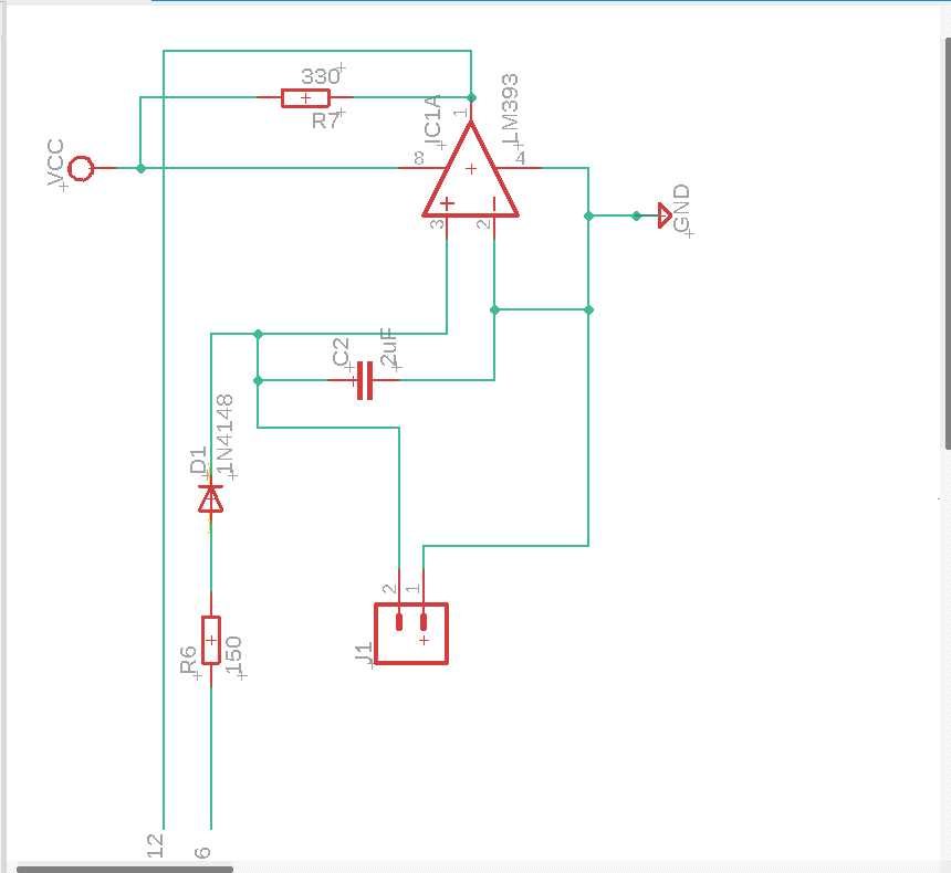
To accomplish that with a microcontroller Simply I need to feed a signal in from the microcontroller. This waveform is affected by the above LC circuit, filtered by the comparator chip, then read back out the other side by the microcontroller. That resulting signal is a square wave, which is an easy target for the Arduino to measure. That timing measured from the square wave can then be used to calculate the inductor’s value using this formula.
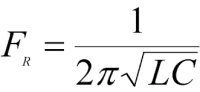
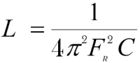
So we could obtain the L value because we know the F frequency that we've just measured and we also know the value of the capacitor because it's a component that we've selected. All we need is to obtain L from this equation.
Designing & fabricating the PCB
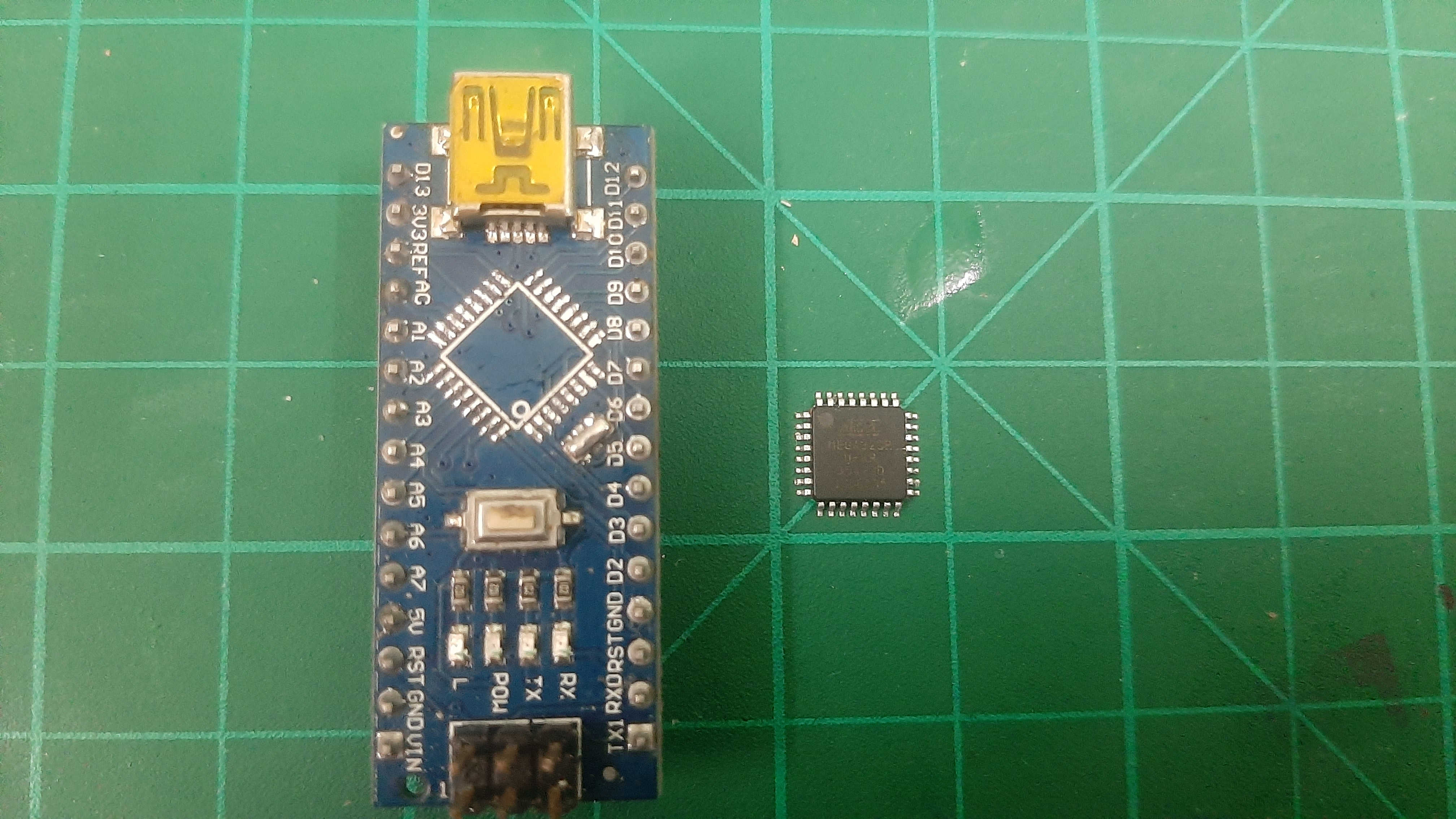
I'm going to use ,The 328p is the chip that is used with the Arduino Uno it doesn't have a native USB connection,I decided that I will one need the ISP pins to programit once and adding a native USB connector will consume a lot of space so I decided that it's not nessery.
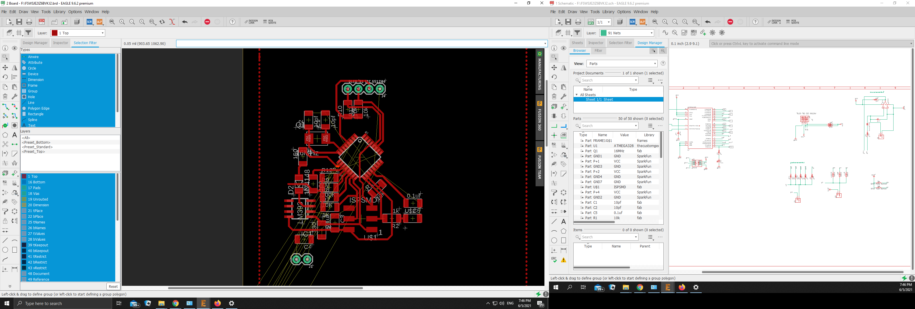
After finishing the ATmega328P-AU microcntroller with the LCR circuits schematic. I converted into the PCB layout and started laying the components footprint down with the PCB space in mind. I tried to save as much space as I can and that forse me t make a multble vias in the circuit.
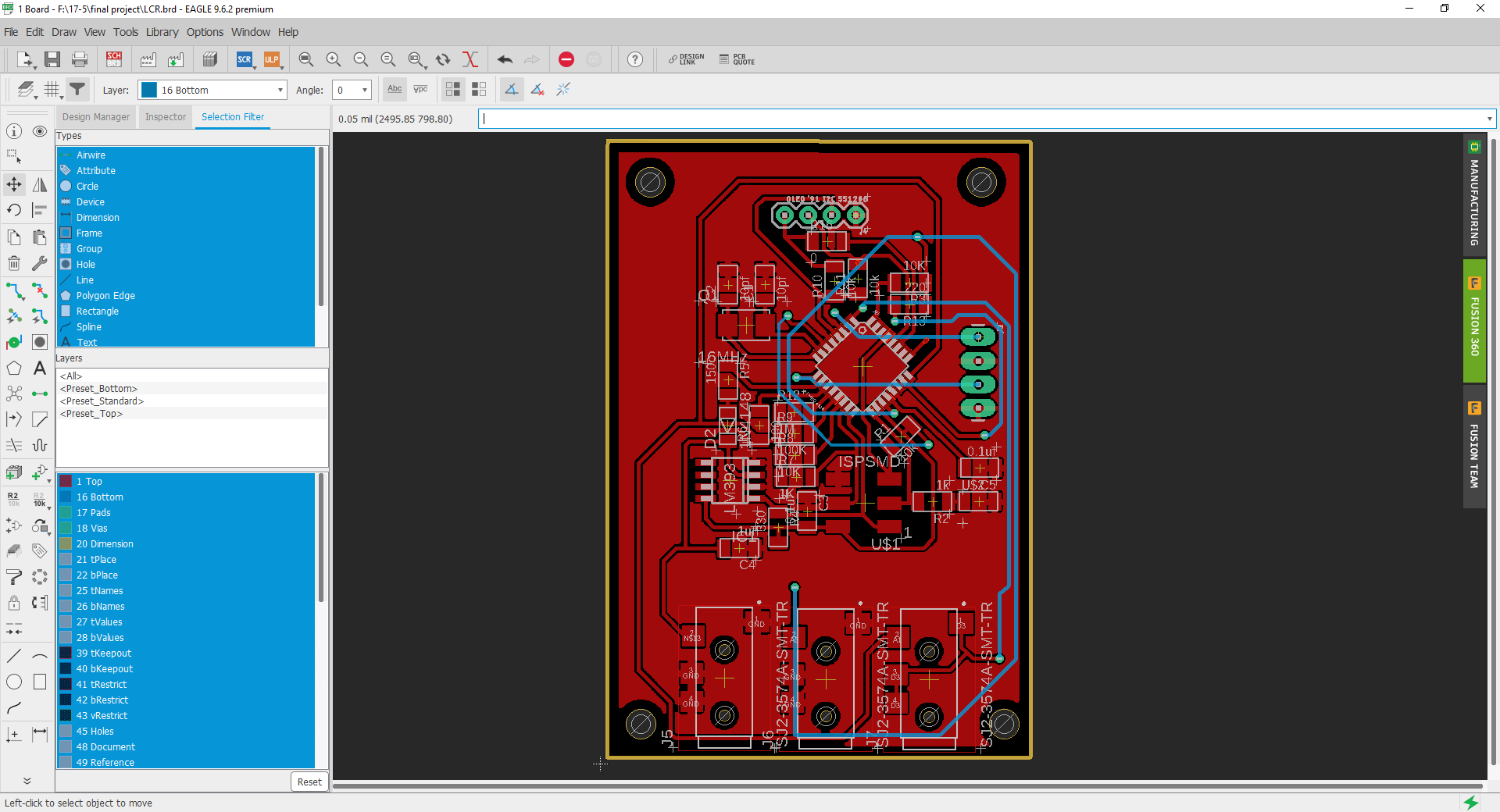
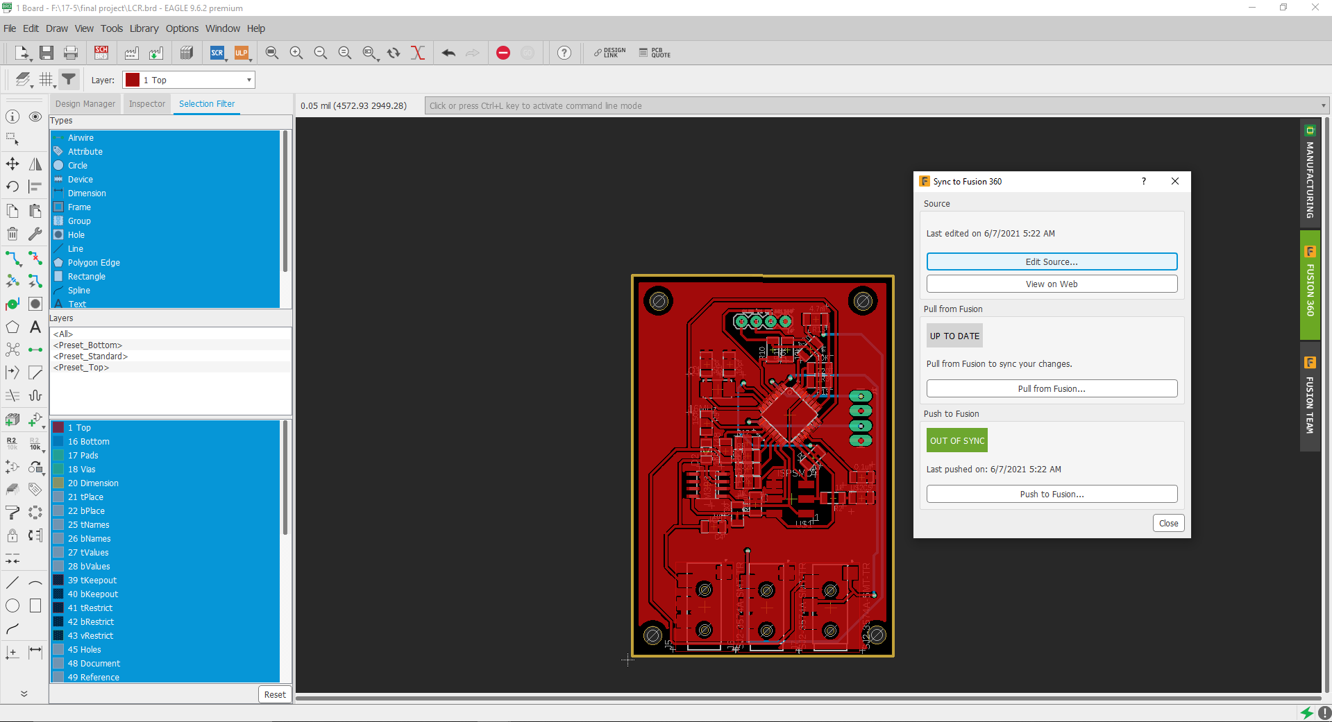
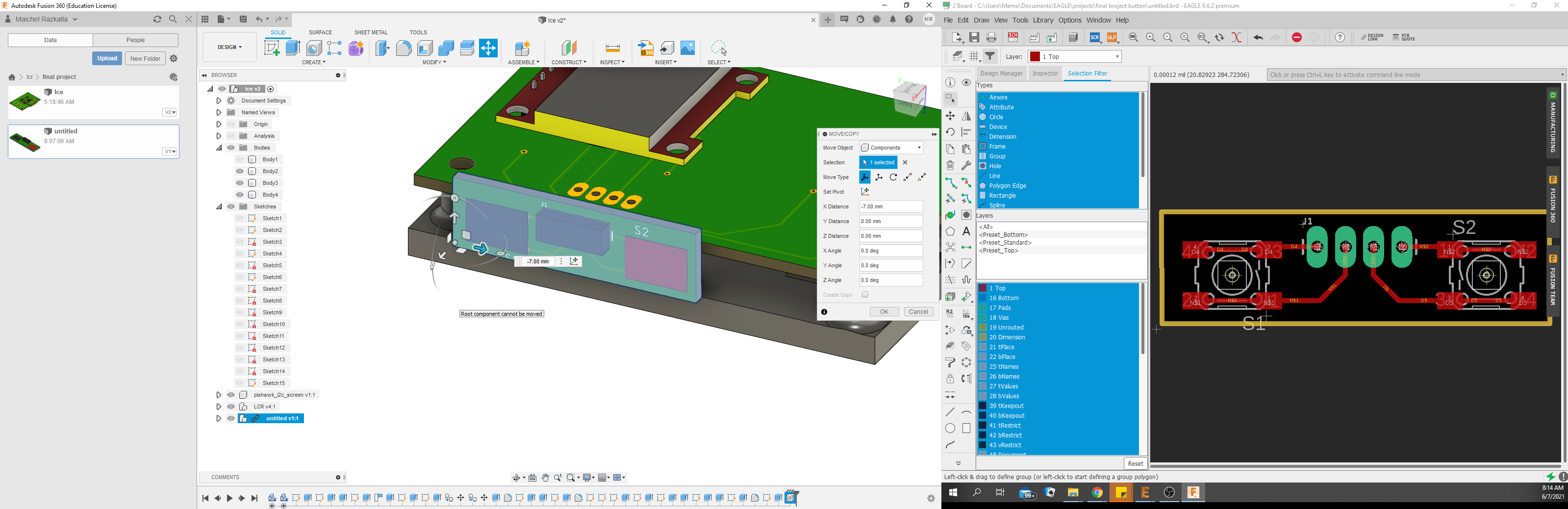
After making sure that everything is working fine and we will not need to change the PCB dimensions, let’s start designing the Fab breadboard enclosure, Bs I had to modify the pcb a little bit and I started going back and forth from eagle to fuchion 360 for making minor changes
cut process.
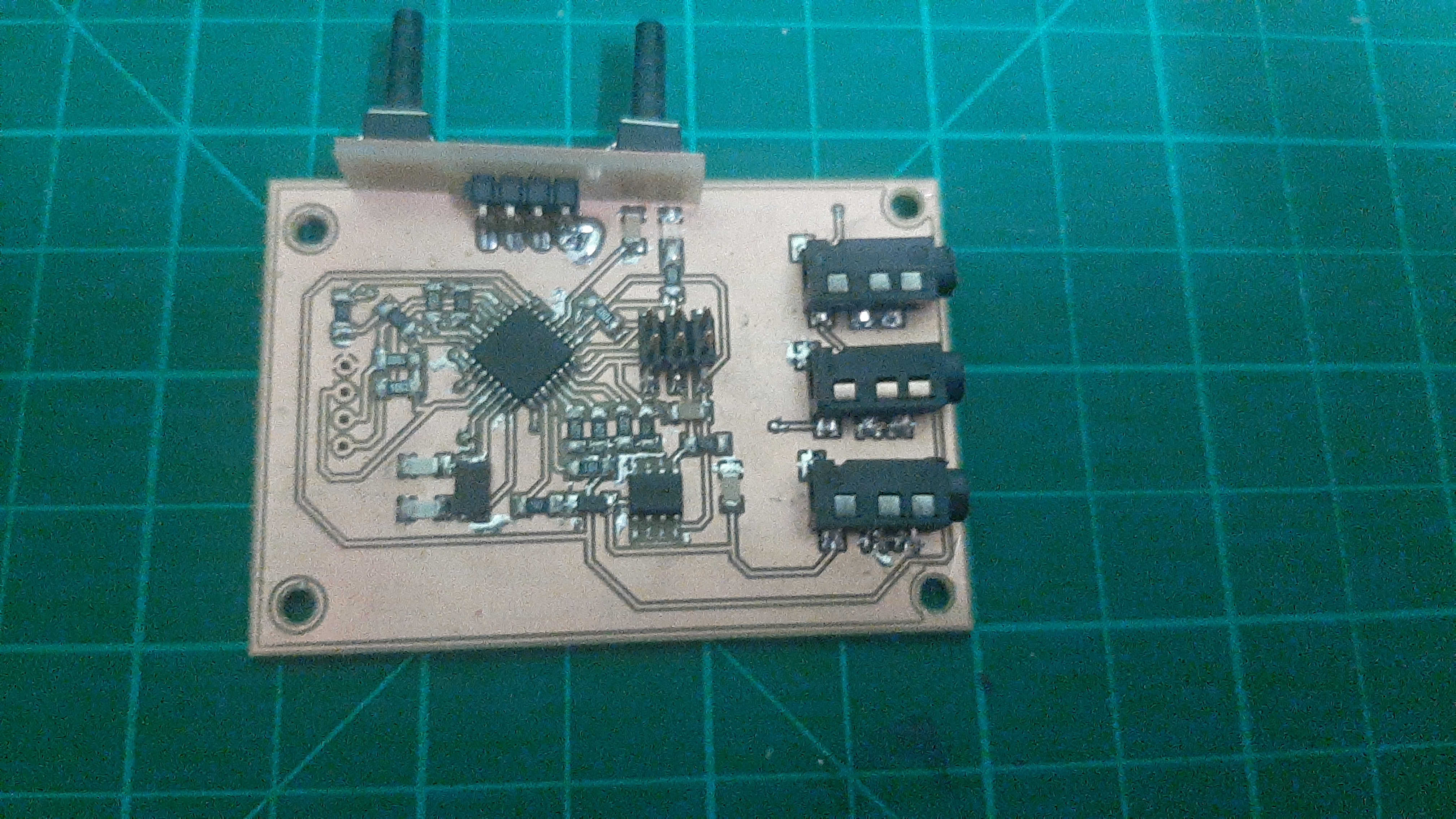
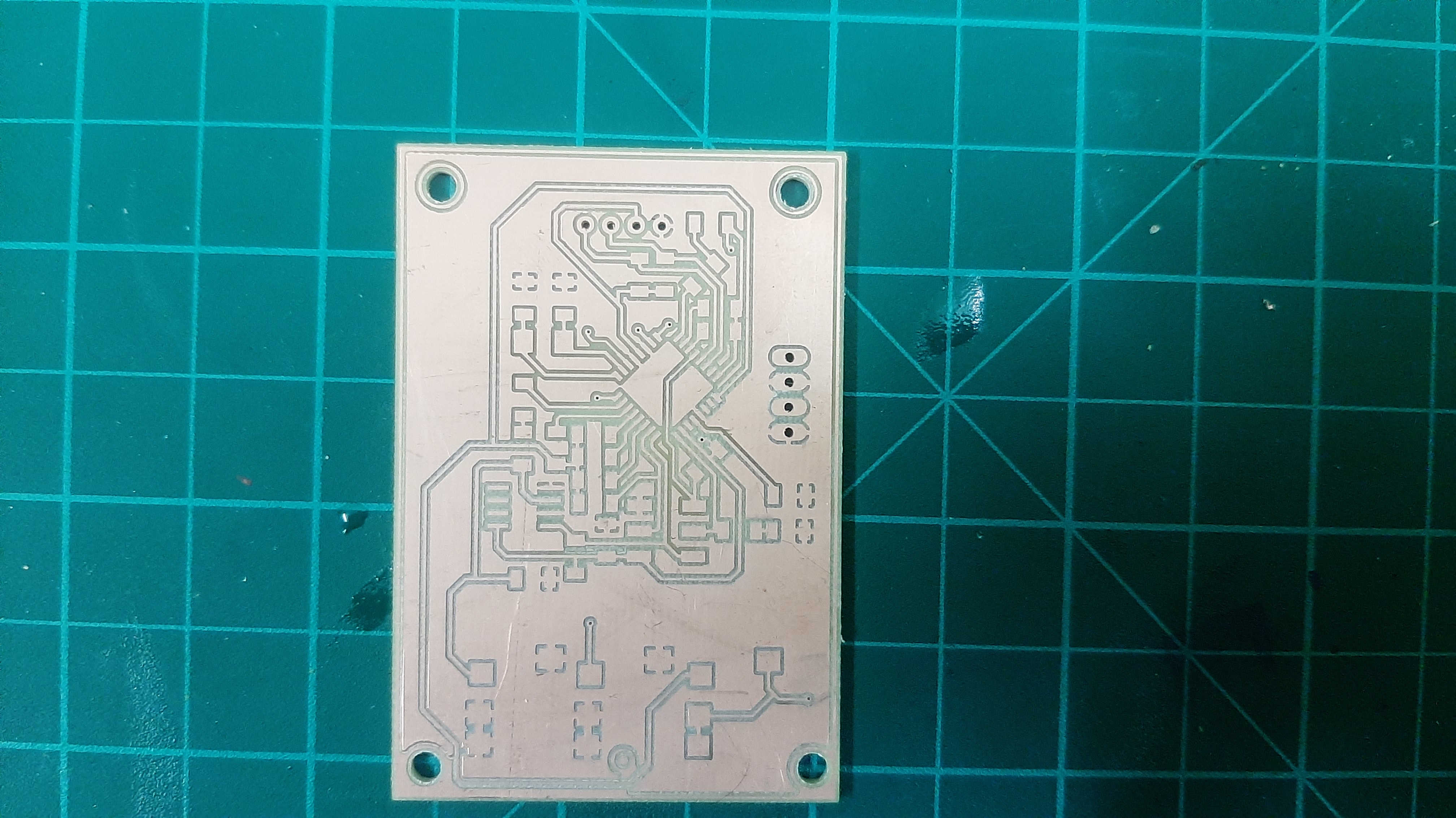
fabricate two side pcb isn't an easy job, and because my component footprint was a little bit smaller than the 1/64 end mill I decided to use 0.010 end mill, the top-side result was great.
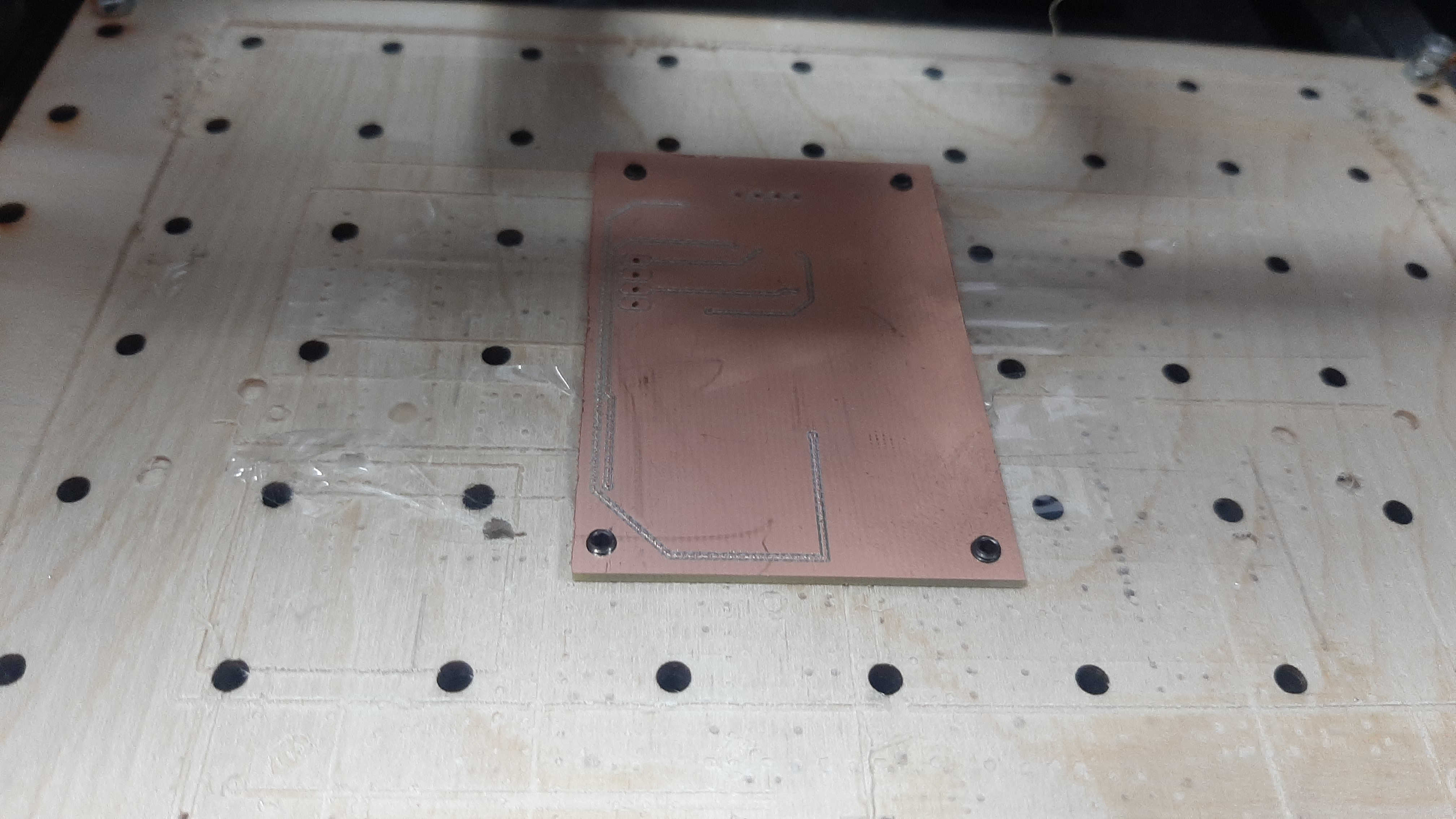
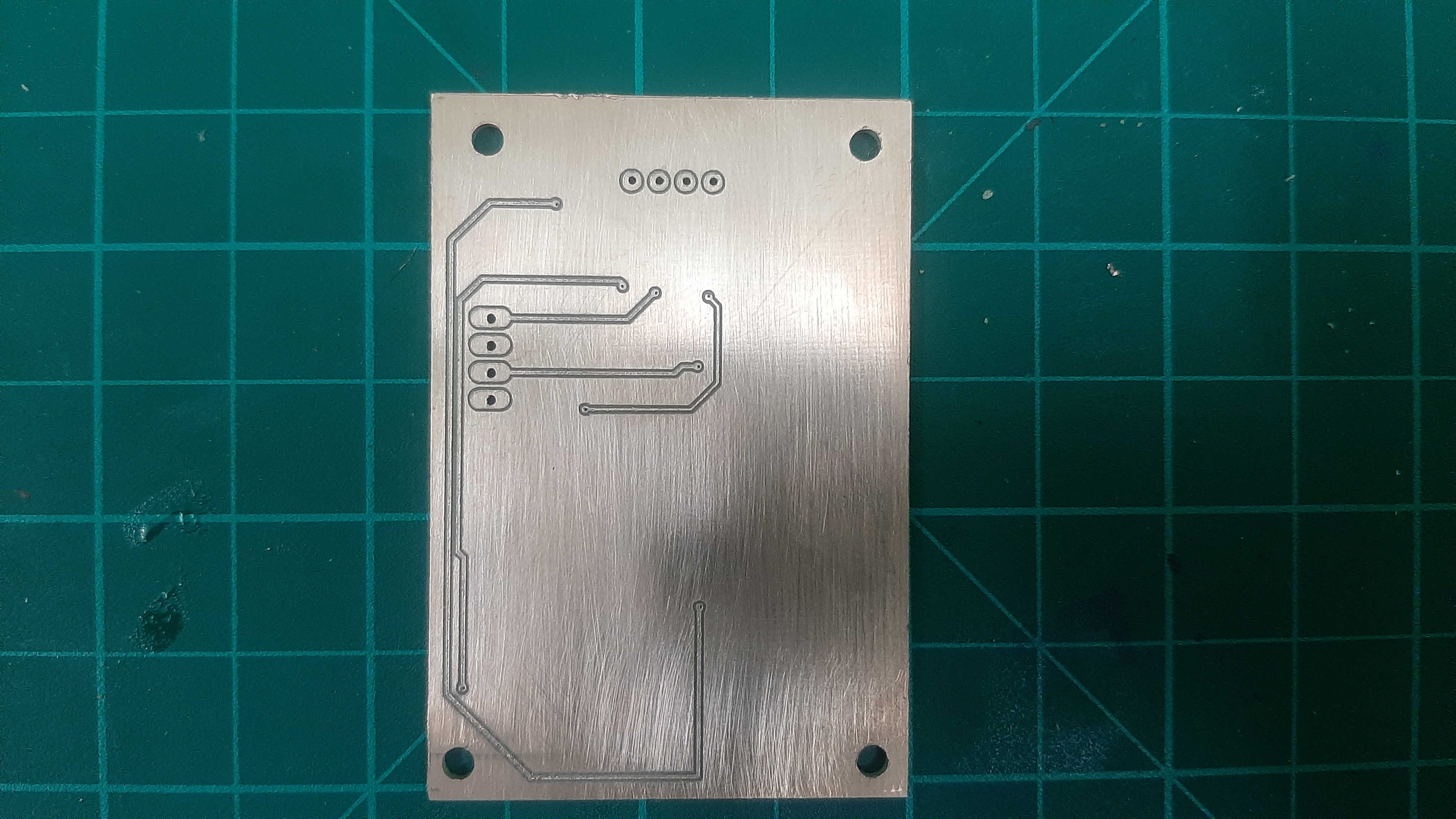
now for the button side, I had to make 3 mm fixation points in the bed to hold the pcb I add a double tape so the pcb doesn't move in the process, result.
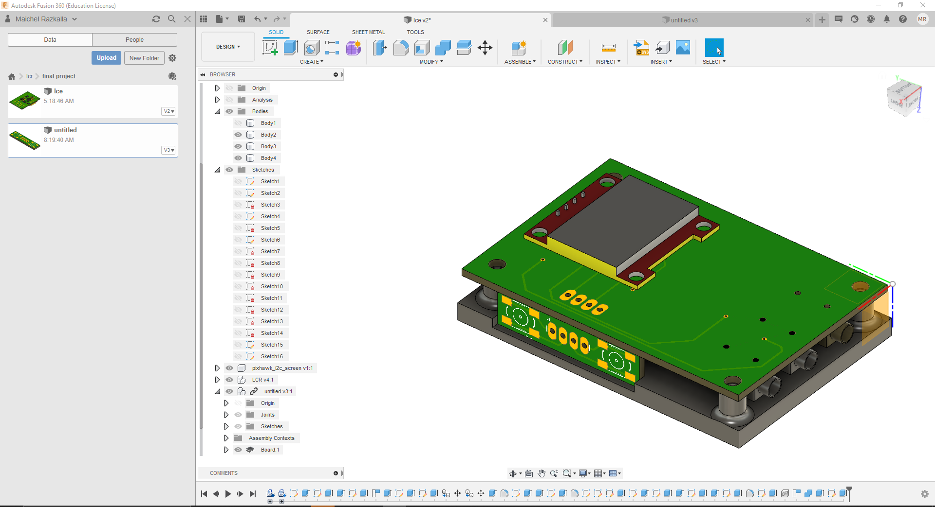
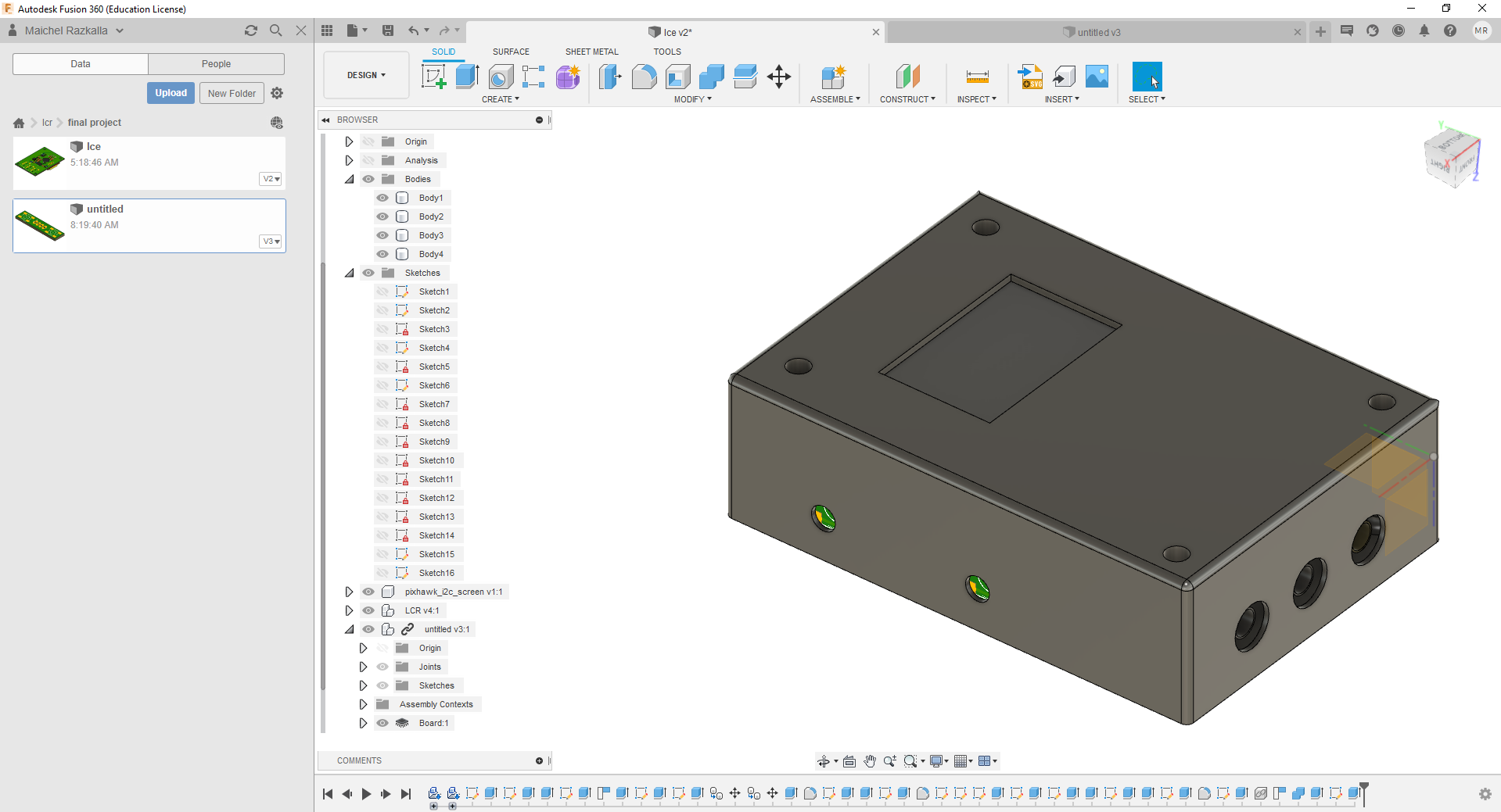
Cad Designing & printing
In the cad design, I was determined to add the pcb so I don't make any mistakes but because the electronic components weren't all have 3D packages, for that some components I didn't take it in my Measurements like the pushbutton but after all most of the design fitted the components and the pcb from the first time.
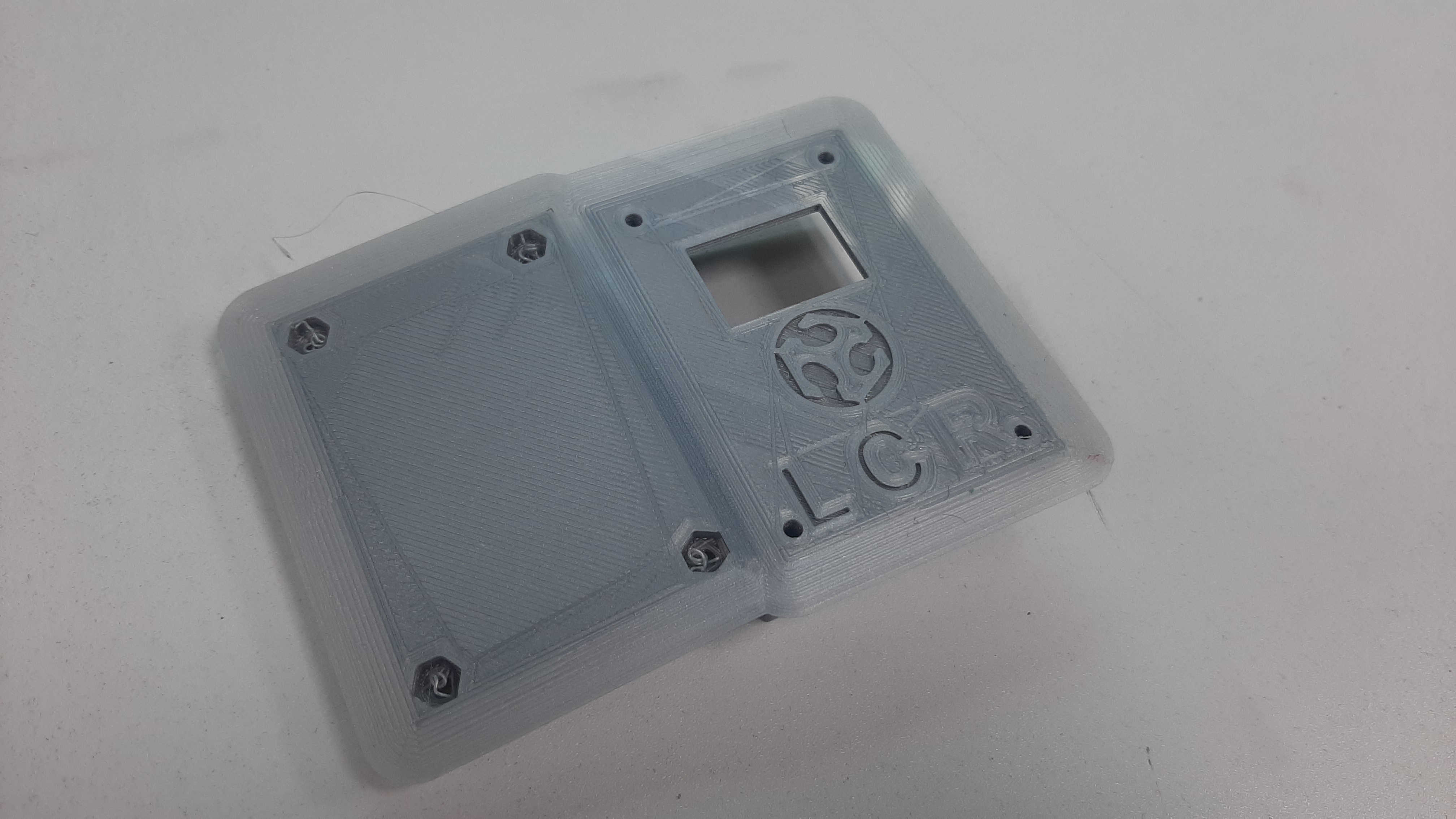
The full 3D printing process.
Result
soldering and debugging