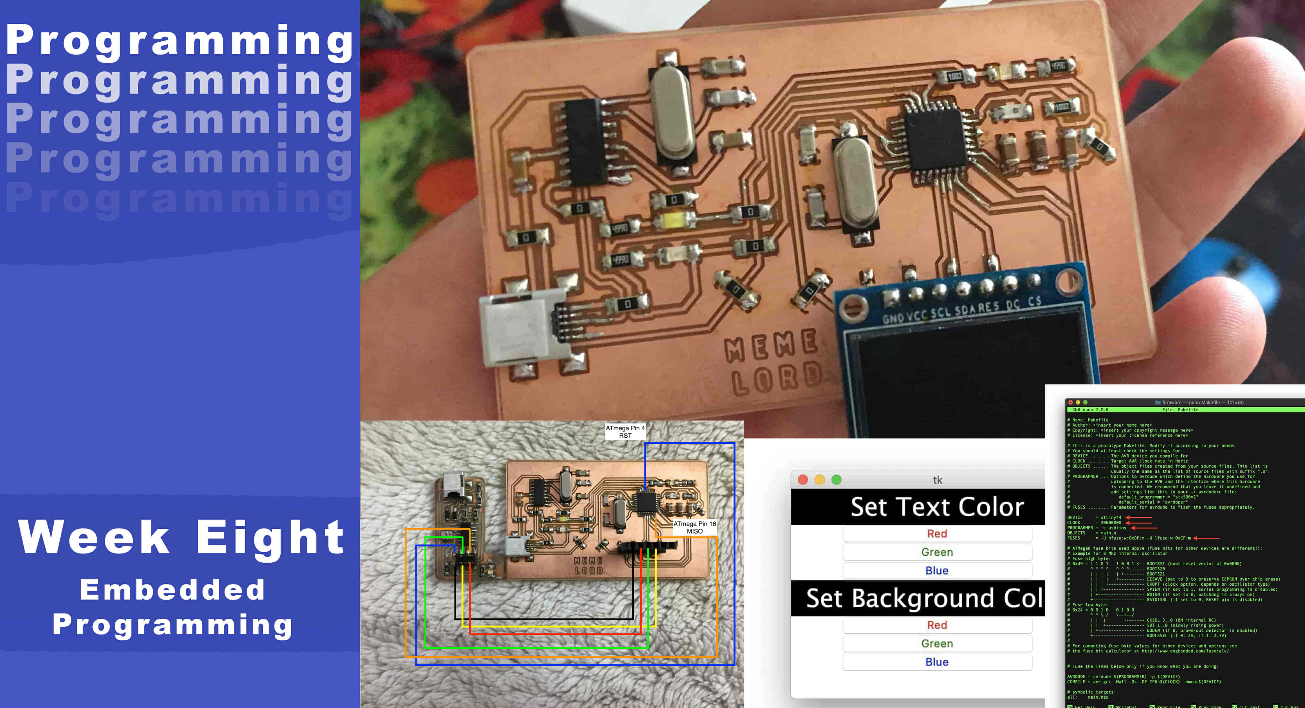
Embedded Programming
What’s Going On?
Two weeks ago, we designed our very first electronic board and fabricated it on the awesome modela machine. This week, we're gonna program this board to make some different actions using as much programming language as we can. Not only that, but I also designed a new ATmega328p microcontroller breakout board this week to make some cool stuff with it.
I’m planning to use Arduino C with the Arduino IDE, and the C language with AVRDUDE. Also, we are gonna build a simple GUI using Python and Tkinter to control the board LEDs through the serial port.
Getting familiar with the main concepts
What’s Microcontroller?
Simply, it’s a whole computer inside a single integrated circuit chip, this small chip contains a whole universe inside it(as Prof. Neil said), the microcontroller contains one or more CPUs that read instructions from the microcontroller flash memory, and stores variables in the RAM while the program is running allowing you to control some input/output peripherals. Not only that, but also it can communicate with the outside world by sending and receiving data to/from another device through serial communication.
Wait, wait! What do those strange words mean?
- Integrated Circuit Chip
IC or Integrated Circuit is a set of an electronic circuit that some guys compress and put inside a small flat piece of semiconductor material that is normally silicon. That tiny silicon piece contains lots of components(maybe millions of resistors, capacitor, ...etc) and the connections between them.
- CPU
Since microcontrollers are only dedicated to one task and run one specific program. The CPU is the brain of the device. It processes and responds to various instructions that direct the microcontroller’s function. Performing some arithmetic functions, controlling I/O peripherals, and talking with the outside world, ...etc.
- flash memory
Is the space that stores your compiled code. The flash memory is of type non-volatile memory which means it guarantees not losing your code even if your microcontroller loses power.
- RAM
It’s the space to store some temporary variables while the program is executing. Once you cut off the microcontroller power it loses all that stored variables.unlike the flash memory.
- Peripherals
Is the answer to how the microcontroller can talk and communicate with the outside world. Examples of peripherals are I2C, SPI, GPIOs, Timers, Interrupts, USB. Let's take an example, “GPIO” stands for “General Purpose Input/Output” Each microcontroller has some exposed metal pins that are for sure there for a reason. With these pins, you can provide power to your microcontroller or control some actuators or even read a sensor data. Say you want to control some motors like changing their rotation direction or speed from your microcontroller upon the accelerometer data. To make all of that you need a way to connect between that system and your microcontroller, GPIOs are the answer.
- Serial Communication
Serial Communication(UART) is one of the available peripherals on some microcontrollers, it allows the microcontroller to talk with different devices. Let’s take an example, say you want to install a temperature and humidity sensor on your house roof, read these sensors data, and send these data to your laptop. Simply, the microcontroller job here is to read the sensors’ data, process it, send it to your laptop through Serial Communication.
I guess we are now on the same page fam, let us do some hardcore programming stuff. First things first, before doing any kind of programming lets take a look at the microcontroller datasheet to know some information about it. In today’s work, we gonna use the ATtiny44A microcontroller. We don’t need to go through a 300 pages datasheet in one day, it’s not a novel or a story. We gonna approach it as a reference, only return back to it when we need to know a piece of specific information.
Lemme share some goods with you, Two-three weeks ago I found a very good book talking about AVRs in general, how to use em, how to program em, and a lot of other interesting topics. Check it out you gonna like it. This book is really amazing.
Microcontrollers are used in many embedded systems applications, let’s look at some consumer products like the air conditioner, the brain of it is a microcontroller that responsible for receiving sensors data like a temperature sensor that senses the current room temperature, turn that input into series of commands to go to the air conditioner compressor to work or not. Or even the microcontroller in your universal remote control translates your key presses into a precise series of pulses for an infrared LED that tells the microcontroller inside your television to change the channel or increase the volume.
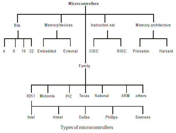
When it comes to choosing your microcontroller, There are a lot of options out there. There are so many microcontroller families are available. Those are 8051, PIC, AVR, ARM, etc. each microcontroller family has its own specifications like the processor speed, flash memory size, RAM size, ...etc.
Today, we gonna focus specifically on the AVR family, the ATtiny25/45/85 they are all great and very small in size, it’s a perfect chip if you only need 5 GPIO pins. The only differences between the 25, 45, and 85 are the amount of program memory (2 kB, 4 kB, and 8 kB).
The ATtiny 44/84, the big brother of the ATtiny25/45/85, with just a few cents more, you get 12 GPIO pins instead of only five. And, it is also cheap.
The ATmega series or family, are a big step up from the ATtiny series. With the Megaxx8 series, you get 20 GPIO pins, a lot of native hardware peripherals like SPI that is not natively supported in the ATtiny series, 16Kb of flash memory, ...etc.
All of these chips come in different packages, they come in through-hole(PDIP) package, Surface mounted like the TQFB which is 1mm spacing that is doable and fun to solder. And, some of them come in the QFN packages too. Today I will use the ATmega328p in the TQFB package.
ATtiny44 With Arduino IDE
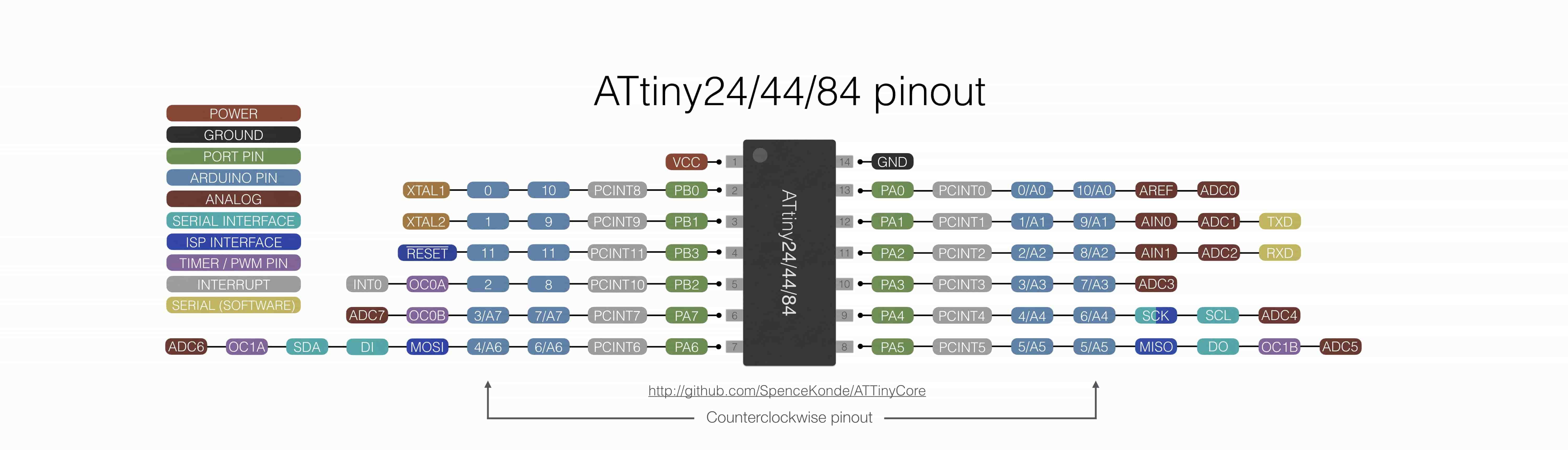
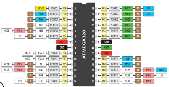
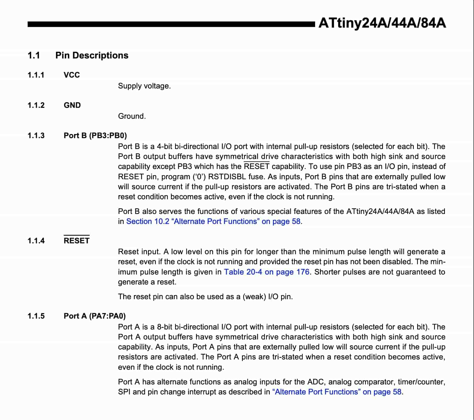
First things first, let’s see the pinout of the microcontroller. It has 14 pins, two pins for powering the board(VCC, GND). And, with two pins for the clock source(XTAL1, XTAL2). We can’t use these two pins as I/O pins. In total, we have 12 GPIO pins that we can use as I/O pins if you are using the internal clock of the chip, or 10 I/O if you are connecting an external clock to the chip. We can access all of these pins and their various functions from within the code by reading from and writing to.
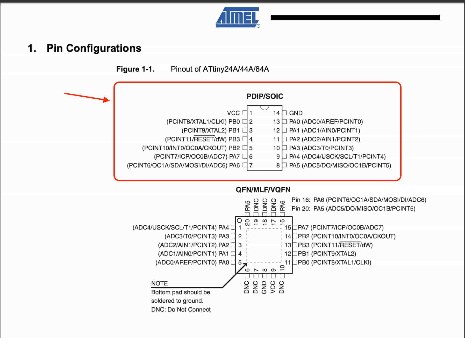
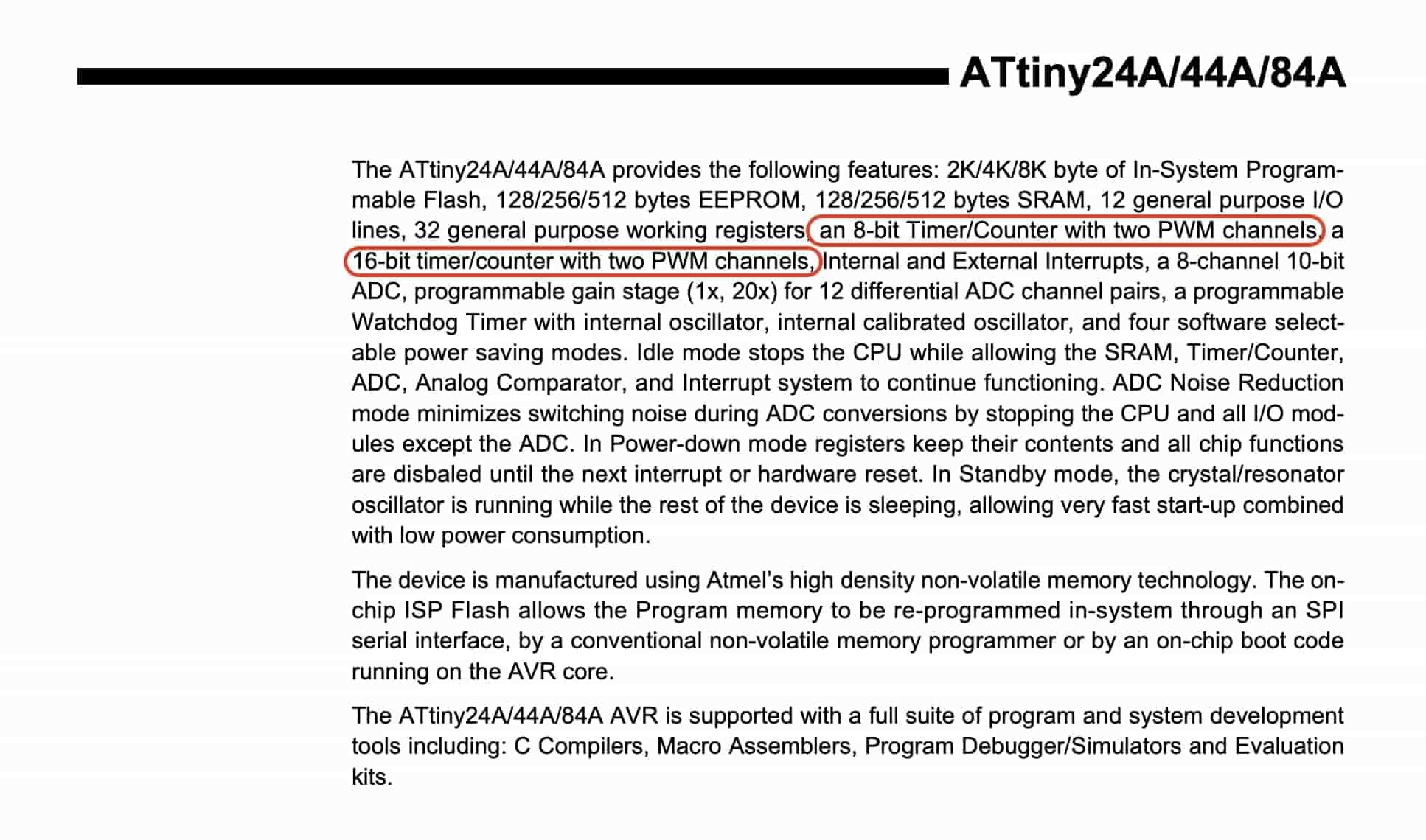
This chip has four onboard PWM pins that you can access within the code to give an analog output voltage(Actually it’s a digital signal put in an analog form) to control LED light brightness, motors speed, and more.
The chip needs a bare minimum configuration in order to work properly. It means using the smallest possible quantity of components that makes that thing run without problems. but later on, we will add some more components to our like LEDs, buttons, pin headers, .. to spice things up.
Now, we know the pinout and the bare minimum configuration setup for this chip to start working! I guess this is enough information for us to start writing some lines of code to execute some simple/basic commands and running our very first program on the board that we designed and fabricated in the Electronics Design week.
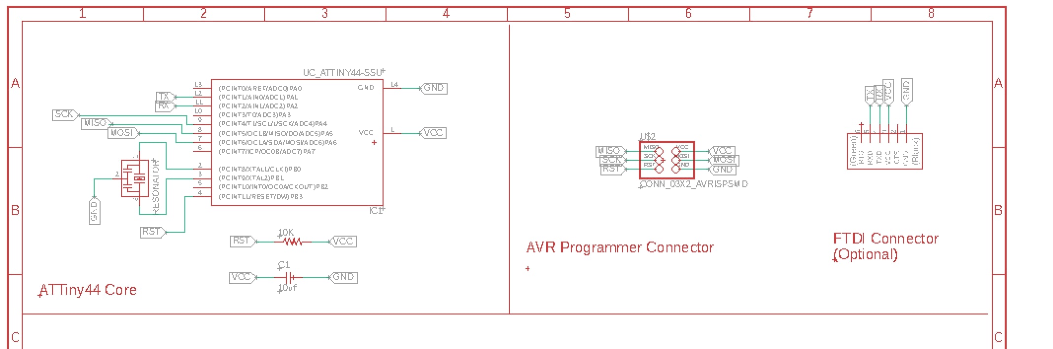
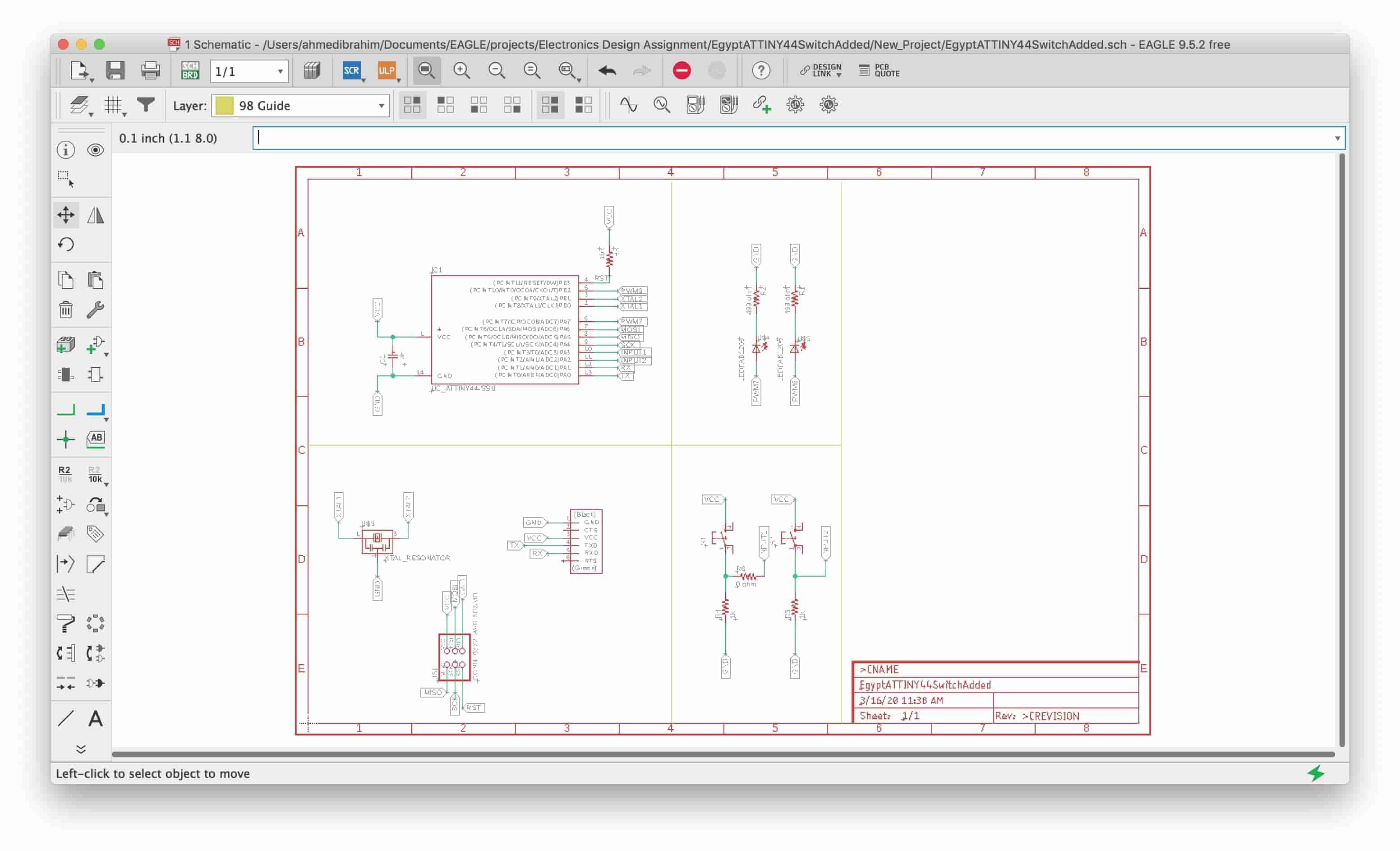
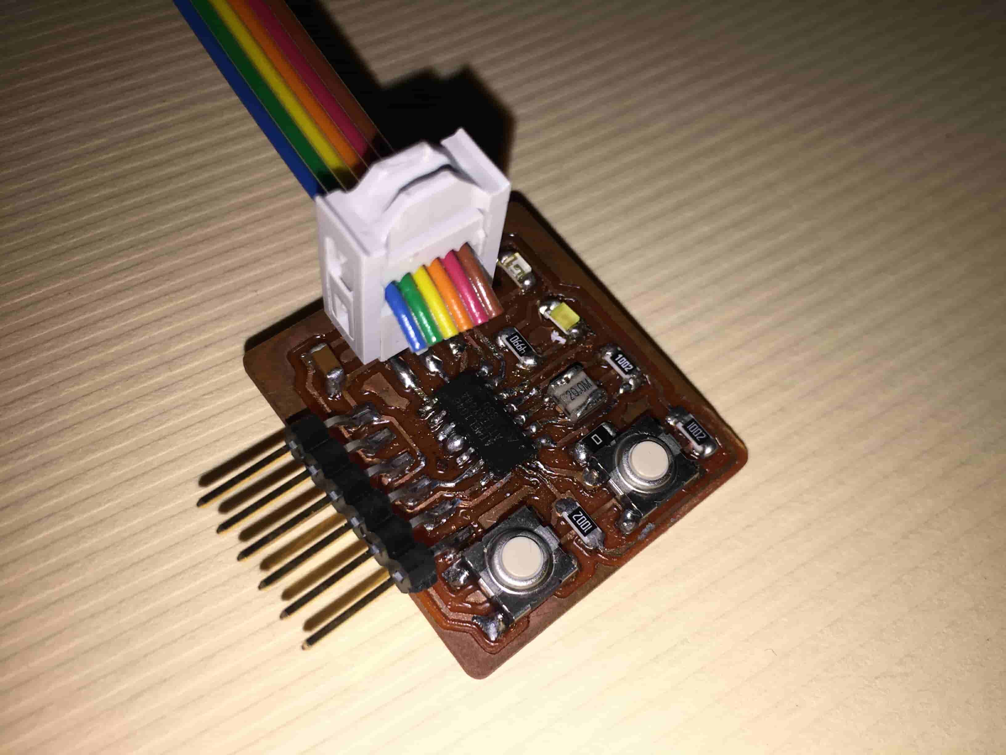
First, here is the board that we designed and fabricated in the Electronics Design week. Simply, it’s an ATtiny44 based board that has two LEDs(Outputs), and two push buttons(Inputs). We need to program it to read the push button input data, and according to the push button state if it is pressed or not, the ATtiny44 will tell the LEDs to light up or not.
Before writing the code we need to set up our development environment first. ATtinyCore works with all versions of the official IDE (from arduino.cc) from version 1.6.3 onwards. Arduino IDE doesn’t support the ATtiny chips natively. So, by installing The Arduino Core files for the ATtiny chip we will be able to burn the bootloader and program the attiny chip. In other words, we will make the ATtiny microcontroller compatible with the Arduino IDE.
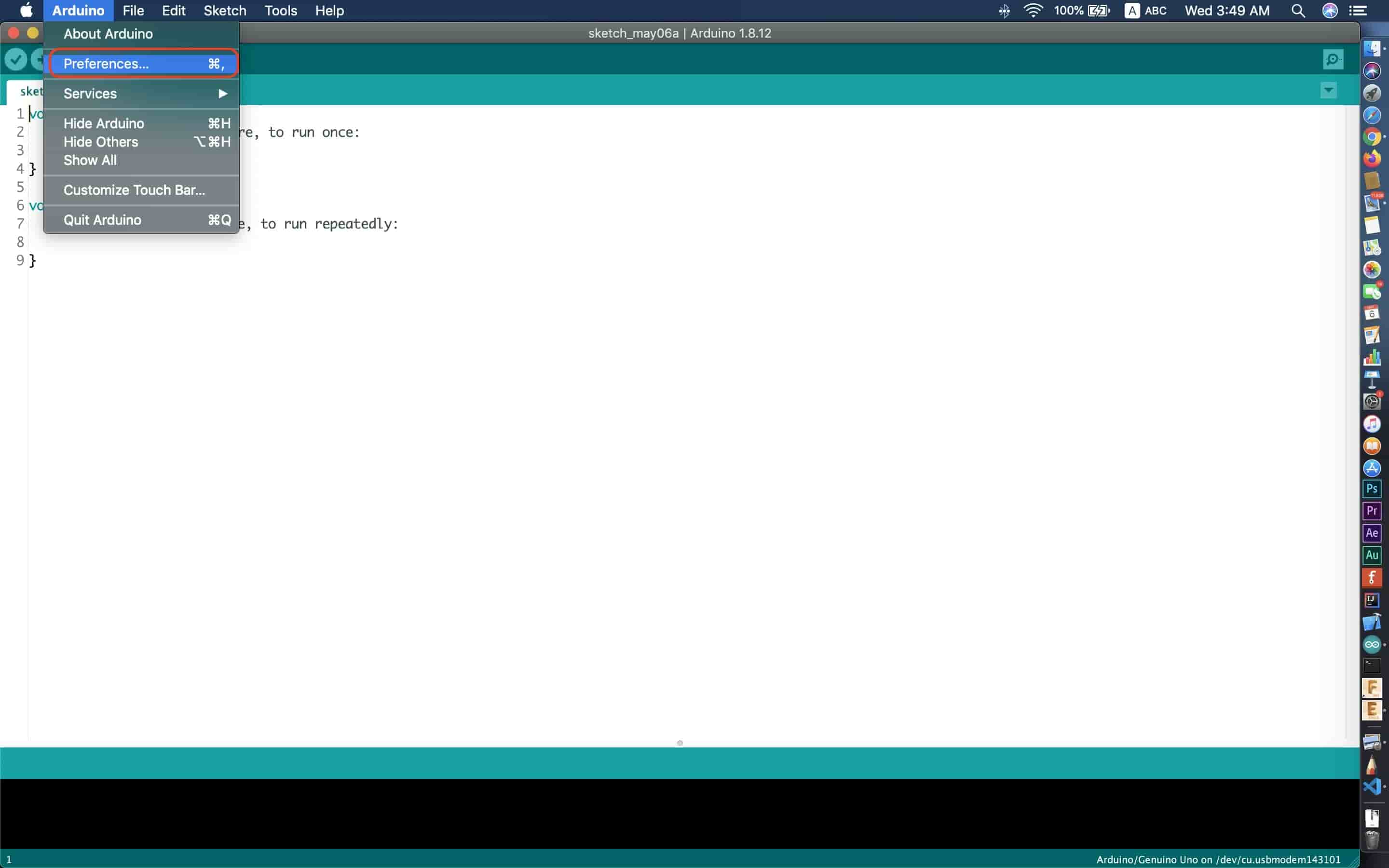
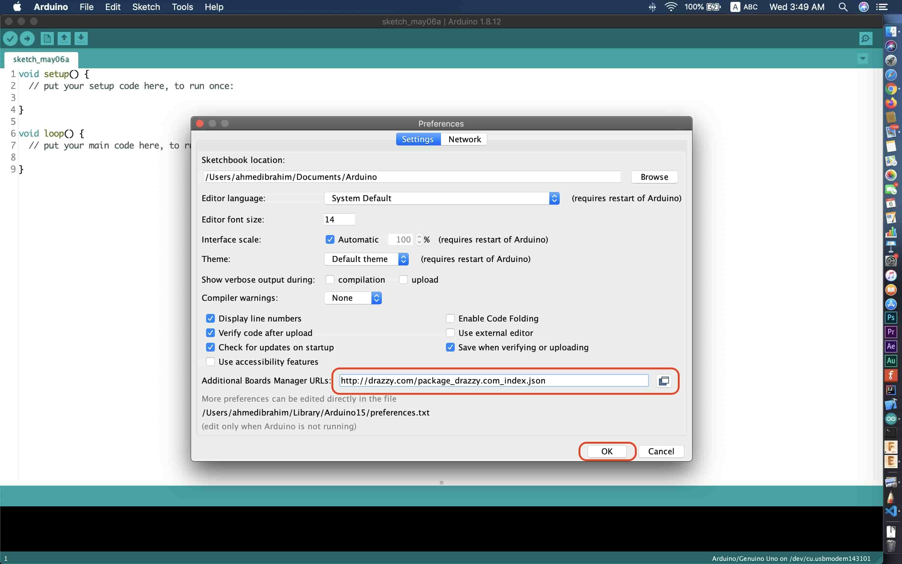
First, we need to copy the Core URL http://drazzy.com/package_drazzy.com_index.json and paste it inside the “Additional Boards Manager URLs” box. Since i’m using a MAC machine.
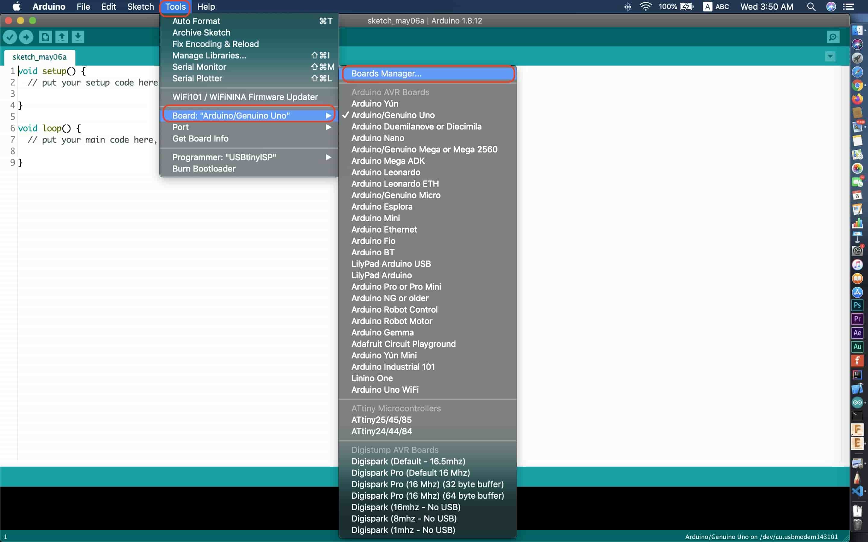
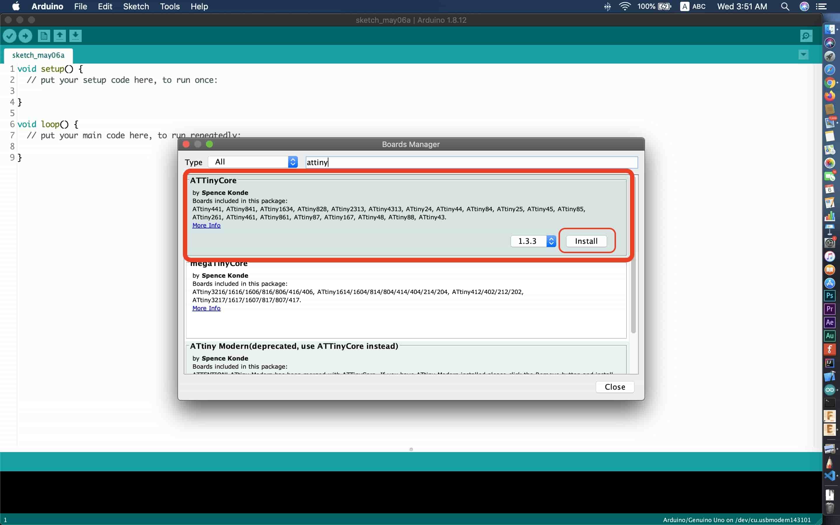
Then we need to install the ATtiny core from the Arduino repository, from Tools → board → Boards Manager. Write “attiny” in the search box, then select "ATTinyCore by Spence Konde" and click "Install". That’s it! Also, you can find the instalation guide from the ATtiny core official Github repo.
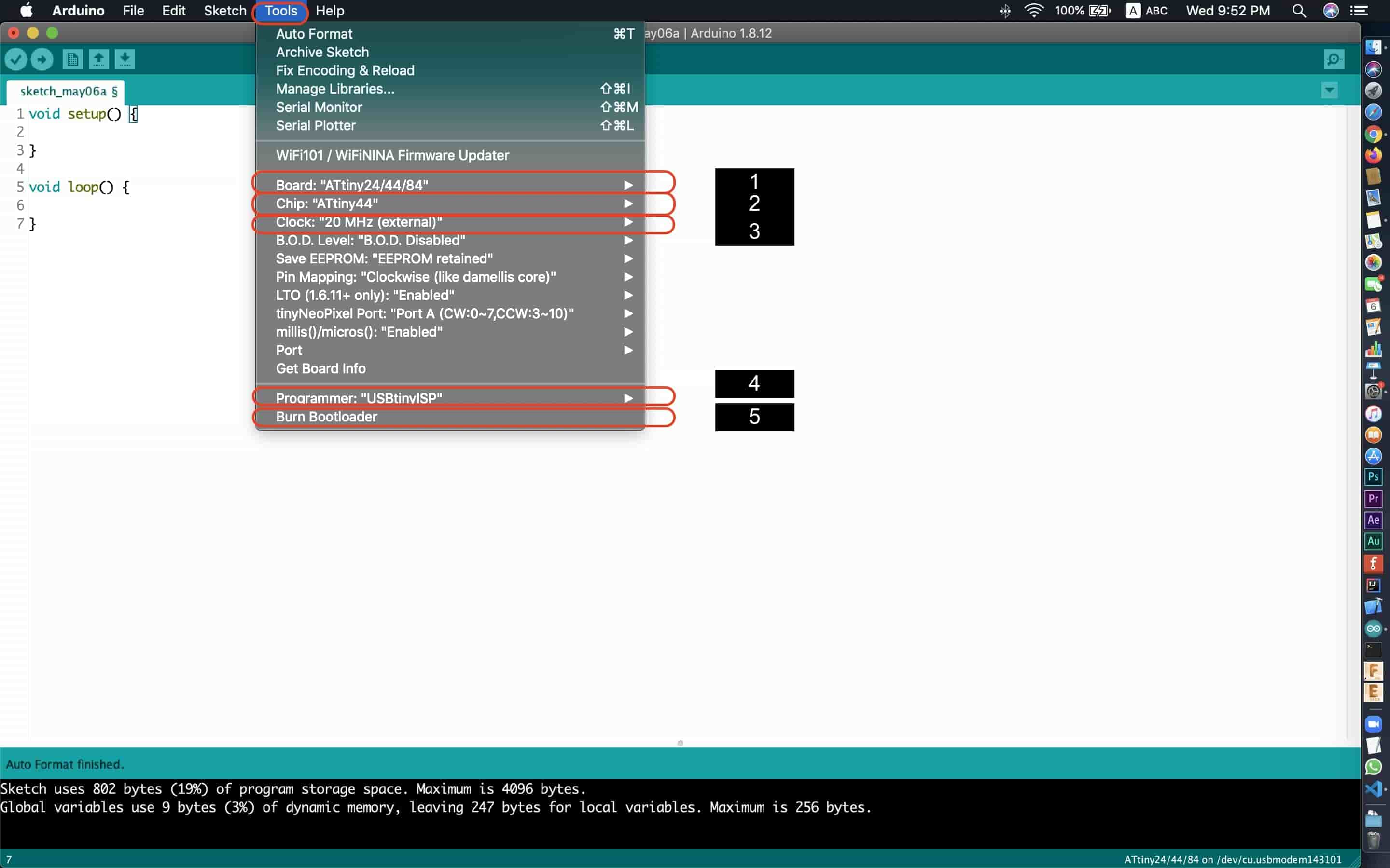
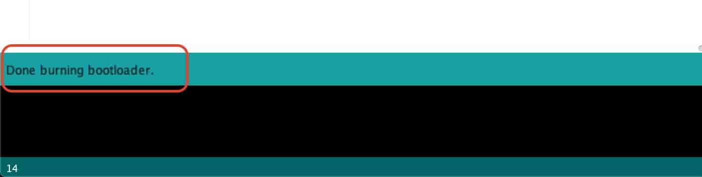
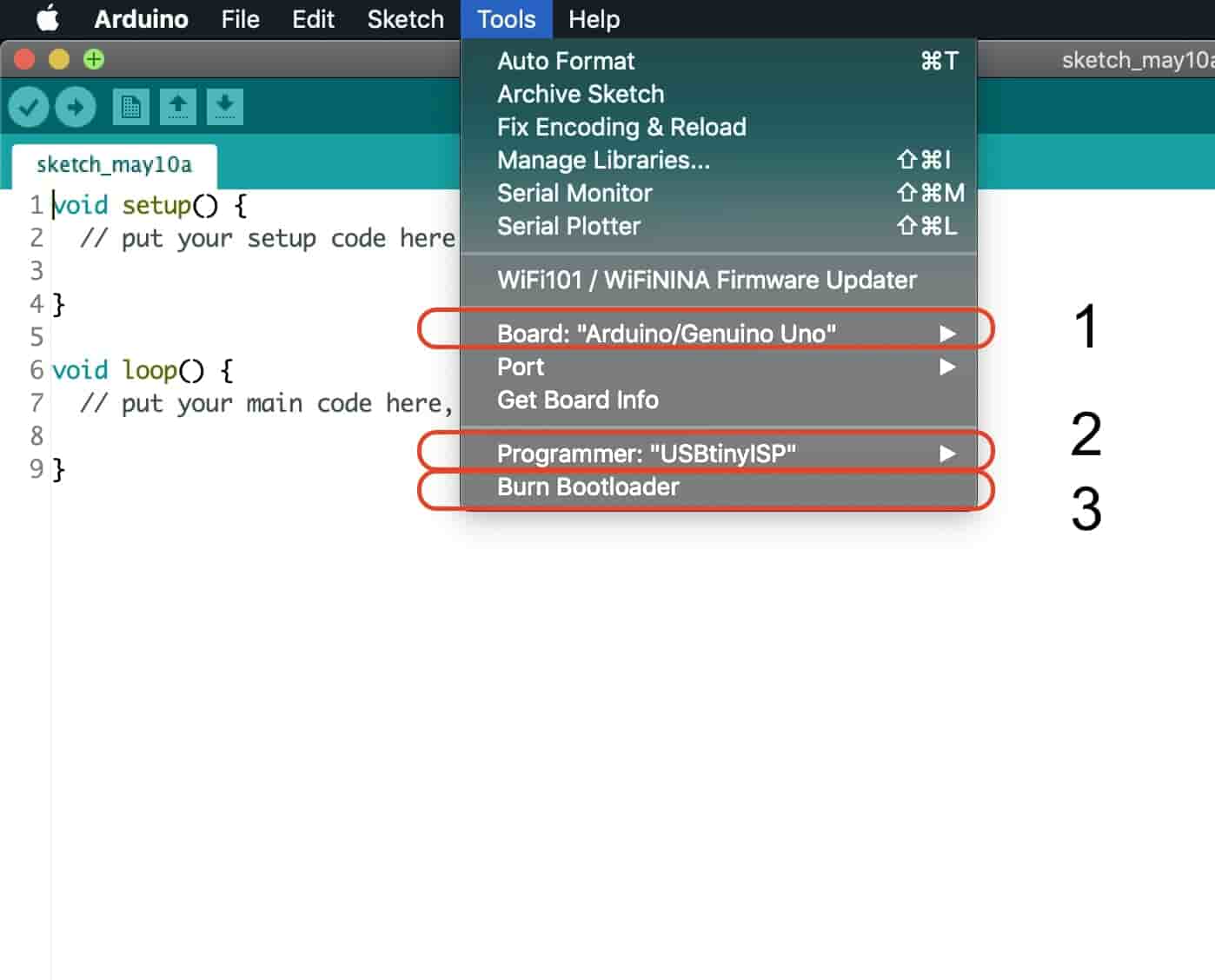
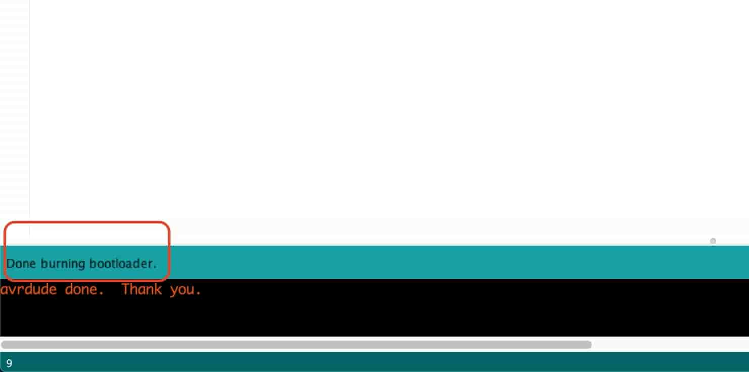
After that, we need to adjust some of these settings, set the board family that you are using. Since i’m using the ATtiny 44, I selected the ATtiny24/44/84 family(1). Then, set the specific chip you are using. in my case i’m using the ATtiny44 chip(2). Then you need to select the clock speed(3) and the programmer you are using(4). Finally, you are ready to burn the bootloader(5) by clicking the “Burn bootloader” button. After burning the bootloader succesfully to your chip you will see that message!
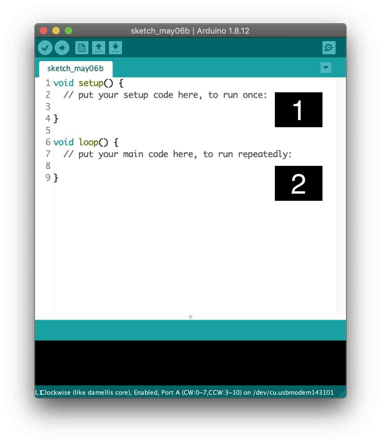
Now, you are ready to fire your bullets fam, let’s test our work so far by making our board blink! Before writing our code, let’s take a look at the structure of our sketch. A basic Arduino sketch consists of two functions called setup() and loop().
The body of setup() function is executed only once only when the sketch starts. Inside this function we initialize pin modes, variables, and libraries, ...etc. After creating a setup() function, Statements in the loop() function will run continuously from top to bottom and then back to the top. If the loop() function contains two statements, the first statement will be executed first, then the second statement, then the first statement again and so on. Inside the loop() function, we are executing our main program allowing it to change and respond.
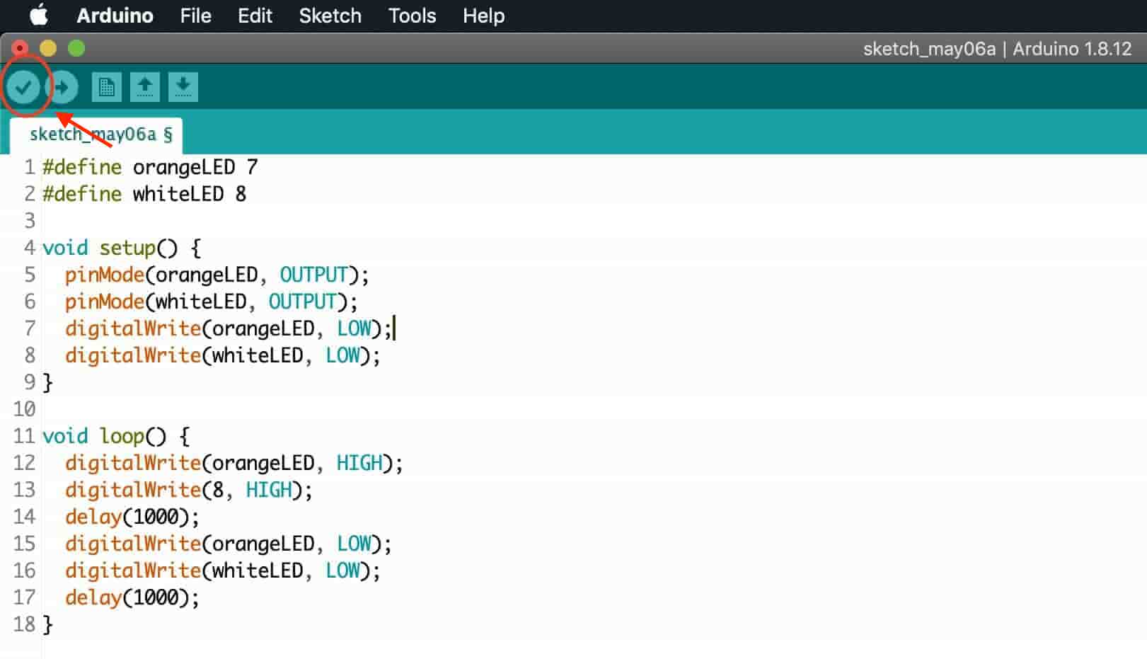
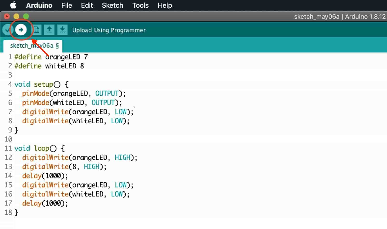
It's a good idea to write a pseudocode for your program logic before doing any kind of actual programming. We need to set the digital pin number 7 and 8 as output pins, turn them on(HIGH), wait one second(1000 milliseconds), then turn them off(LOW), wait one second(1000 milliseconds), and repeat.
I'm assuming that you already wrote your program logic on a piece of paper as a pseudoCode, let’s write an actual code on the Arduino IDE.
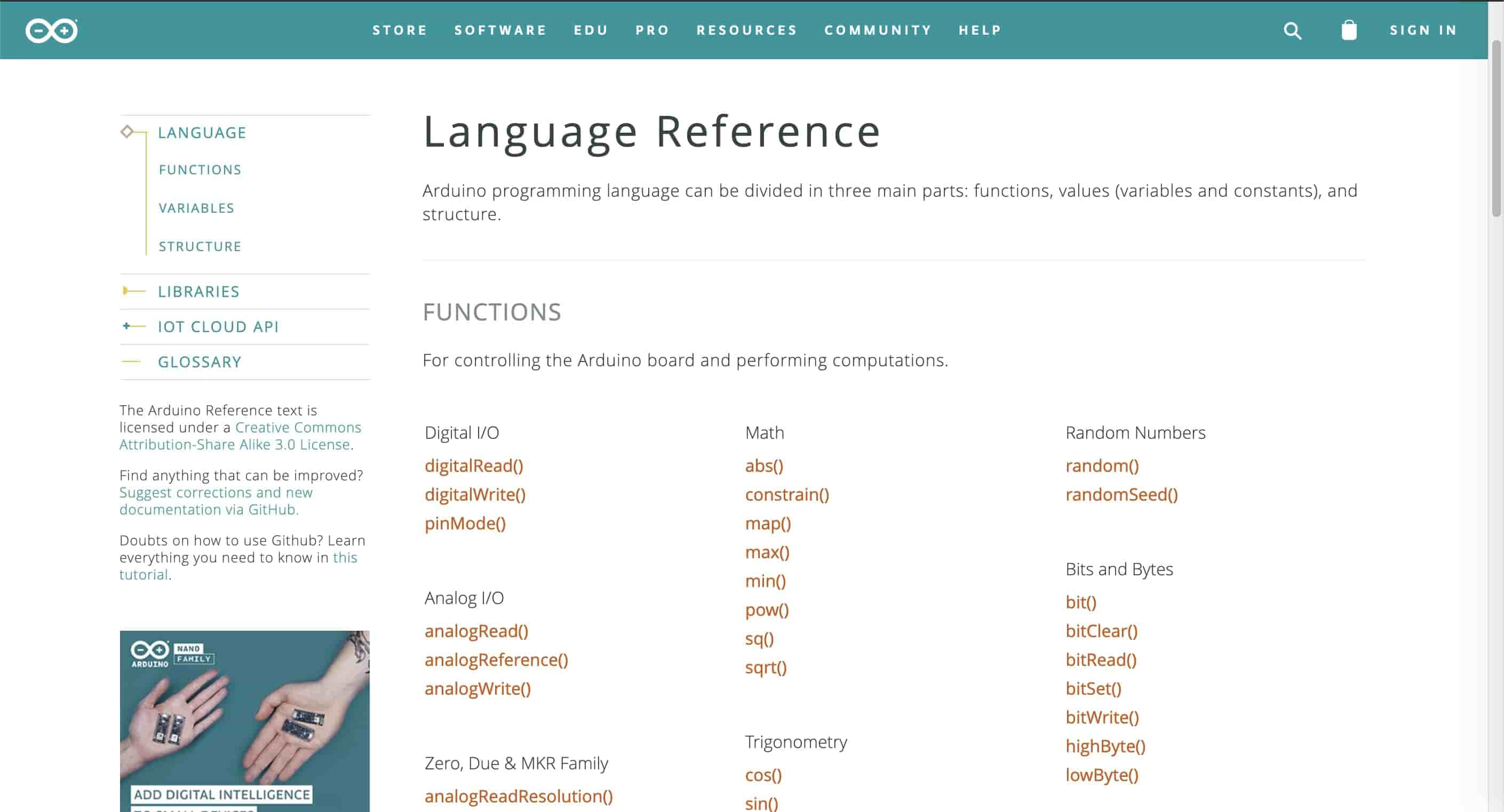
We are using some strange functions here, like the digitalWrite(), pinMode(), and delay() functions. What the heck is these functions doing! Ok, the best person to answer these questions is the language reference. Any programming language has its own documentation or reference that explains how these programming languages work and an explanation for each built-in function. Just like the datasheet of the electronics devices.
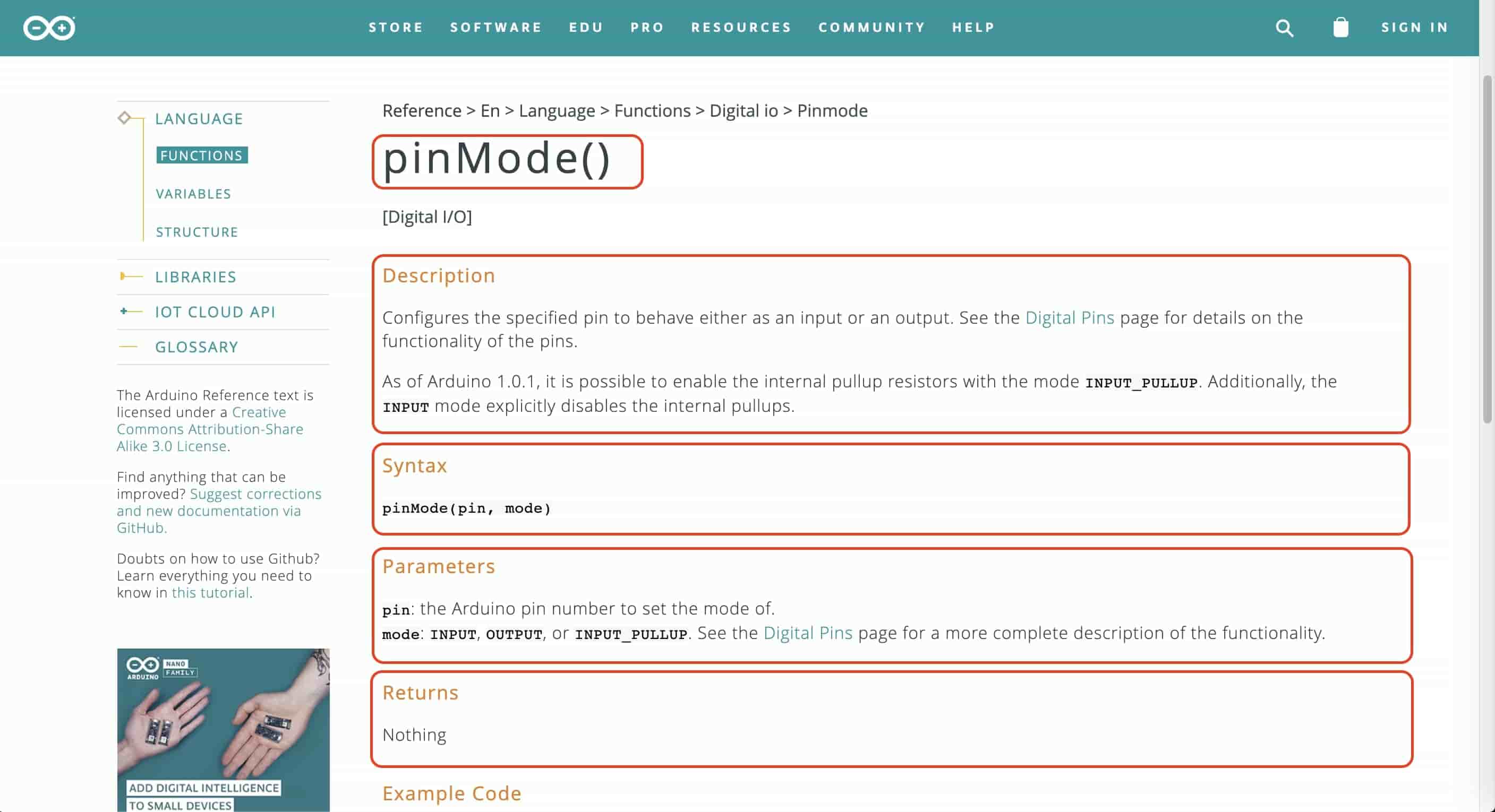
So, to know how these functions work, we opened the Arduino C language reference, and selected the pinMode() function. It says that this function is responsible for setting the microcontroller GPIO pins to either input, output, or input_pullup, it takes two arguments or parameters, the first one is the Arduino pin number to set the mode of, since we are using an ATtiny board with a third-party Arduino core, we need to look at the ATtiny44 pin mapping from the SpenceKode Github Repo to be able to write the right pin numbers in the program.
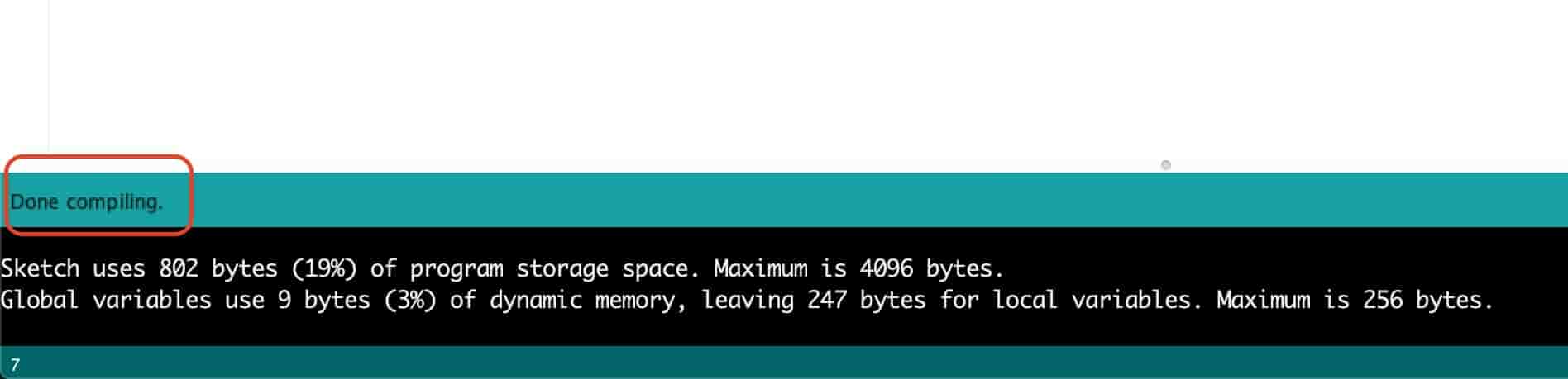
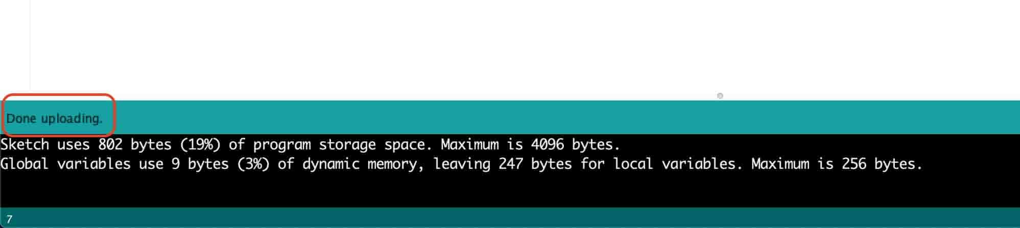
To know how the digitalWrite(), and the delay() functions work, look at the language reference. Before uploading the code to our board, it's always a good idea to verify that the code we wrote has no errors, I mean by errors here the syntax errors, the compiler will not tell you about any logical errors. If your code has no errors you should see that “Done Compiling” message.
After making sure the code has no errors, it’s the moment of truth! Upload the code to your board by just clicking the upload button.
Reading Push Button Input And Adjust Blinking Speed
After we tested our work and development environment and we now sure that our system is working correctly, let's try another example. We need to read the two push buttons state and according to its state whether it pressed or not, we will take a different action.
I wrote a simple program that increases and decreases the LEDs blinking speed according to the two push buttons state, one push button for increasing the blinking speed, and the other one for decreasing the blinking speed. It's pretty simple!
As you can notice, I’m using the millis() function instead of the delay() function. Because the delay() function is blocking anything coming after it until it finishes the delay time. But the millis() function Returns the number of milliseconds passed since the Arduino board began running the current program. We can achieve the same delay() function functionality with using the millis() function by subtracting the last time the order got executed and the current time. The result of this subtraction is the interval between the last time the order got executed and the present. By comparing that interval by the value of the delay time that you want to achieve. You can get the same delay() function functionality with more accuracy and without blocking the whole code. which is called multitasking. That is what we are doing in the previous code example.
Meme Lord board based on CH340G and ATmega328P
All the boards I made were based on the ATtiny family. I have never used the ATmega328P microcontroller Since the beginning of the diploma. So, I thought about why not to make one. Specially that my final project involves an ATmega328P microcontroller with CH340G USB to Serial IC. I started searching online for the CH340G USB to Serial IC and the ATmega328P datasheets.
Why CH340G with ATmega328P? Ok, The 328p is the chip that is used with the Arduino Uno, but it doesn't have a native USB connection, which is useful for easily uploading new programs to it. This means we must use an external programmer or another chip to program it and pass serial data. In the Uno this is done by another ATmega microcontroller, the 16u2. But these chips are a bit more complex than is really necessary. Usually an FTDI FT232R would be used instead. But here in Fab Lab Egypt the smallest end mill we have is the 0.4mm which can’t cut between the FT232R pads because the clearance between them is very very small. So, I decided to use the CH340G which has a larger clearance and is machinable with the 0.4mm end mill.
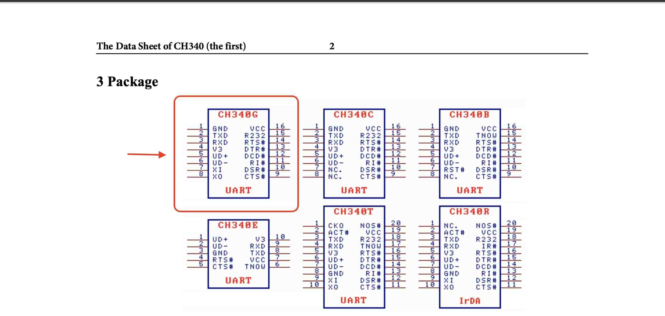
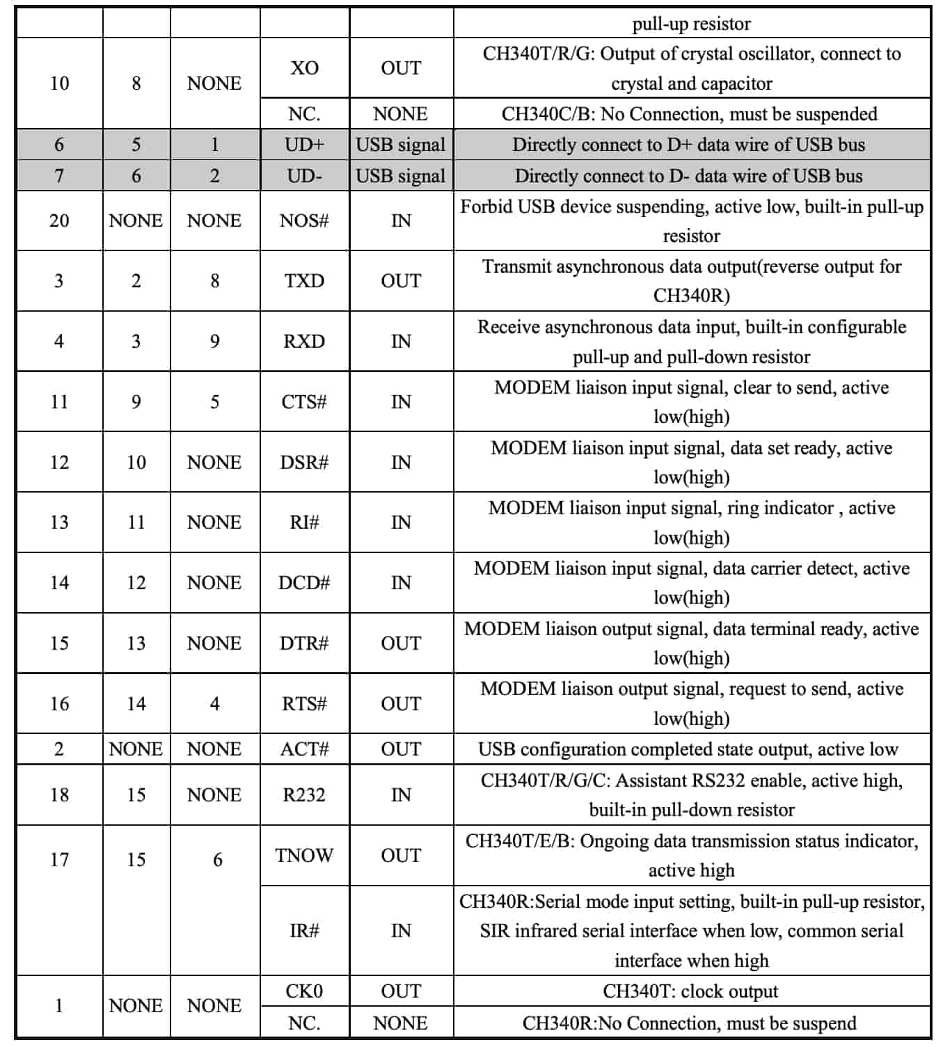
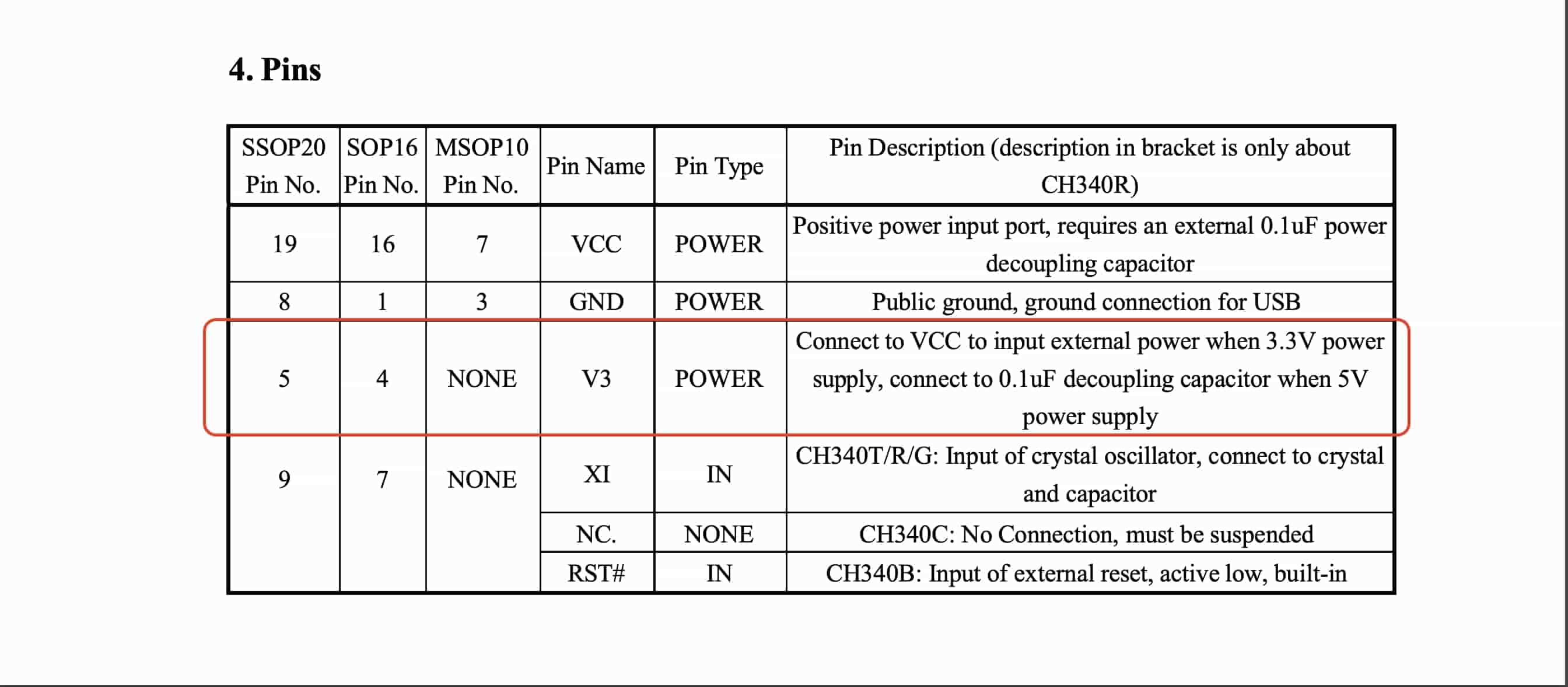
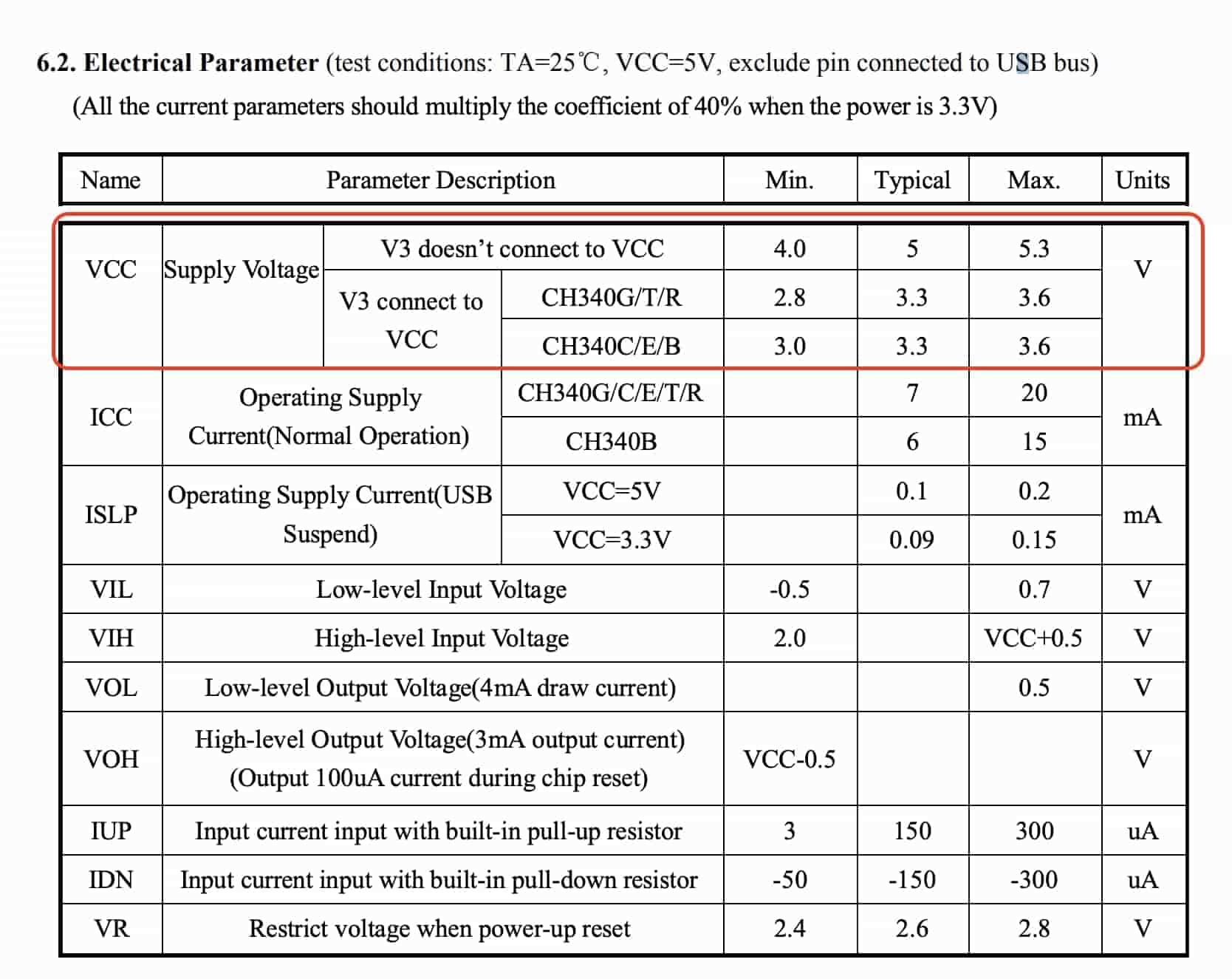
Before starting any kind of designing we need to understand how these chips work, their electrical requirements, pinout, and typical application. All these data are available in the chip datasheet. First thing, I need to know the CH340G IC pinout and it’s description, it’s electrical parameters, and looking at the wiring examples they are providing in it’s datasheet.
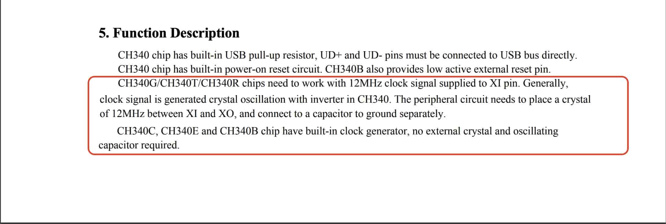
Here’s the CH340G IC pinout and each pin description. Very important note here, the V3 pin must be connected to a 0.1uf(100nf) decoupling capacitor when you are supplying 5V to the VCC pin. But, if you are supplying 3.3V, connect the V3 to VCC(3.3V). Unfortunately, the CH340G needs an external crystal to function, which the FT232R doesn't require, and that makes a circuit a bit more complex. Fortunately, WCH seem to have acknowledged that this isn't ideal, and have released a series of chips which perform the same function with the oscillator built-in. In particular, the CH340C, but today we are using the CH340G IC that needs a 12MHz crystal and capacitance not the CH340C IC.
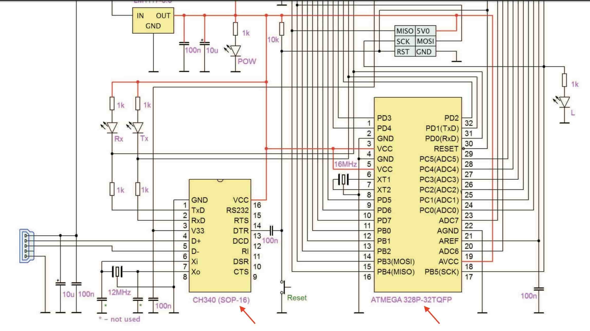
I guess we now have a good overview on how to use this CH340G USB to Serial IC, let’s take a look at the second part, the ATmega328P datasheet. As we can see, we got the pinout of the microcontroller. And a full description on how to use and wire them, and how to connect the external crystal oscillator with the microcontroller. The same concepts we talked about on the ATtiny44 datasheet.
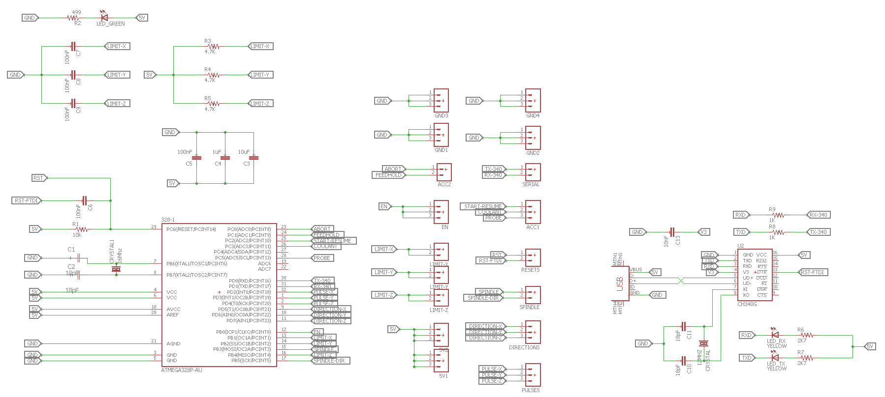
One more thing, I feel that I’m lost in the middle of these all information :D I wanna see anyone used the CH340G IC with the ATmega328P in the prior fab academy rounds or even open-source projects outside the fab academy to link all these information together and see if they are noting something special that I don’t know. I searched online And I found the SatchaKit GRBL which uses the CH340G with the ATmega328P. The connections between the CH340G and the ATmega328P is pretty simple, the VCC and GND are connected to the 5V power, the data lines D+ and D- of the USB are connected directly to the D+ and D- pin of the CH340G, TX and RX on the CH340G need to be swapped over and connected to the RX and TX of the ATmega328P through a 1K ohm resistor respectively(these 1K ohm resistors caused a problem in my case, the board didn’t work with these 1K resistors. It worked after I replaced them with 0 ohm resistors). DTR should be connected to the 328p's reset pin through a 100nf capacitor, which is apparently important for making sure the 328p doesn't restart too soon after being sent the reset signal. And for sure the TX and RX LEDs light up(blink) whenever there is a communication between the ATmega328P microcontroller and the computer through the USB to serial converter chip(CH340G). Pretty simple!
Also I found an Arduino nano open-source schematic that uses the ATmega328P and the CH340G IC. The connection between them(Ch340G and 328P) are the same as the Satsha GRBL board we discussed before.
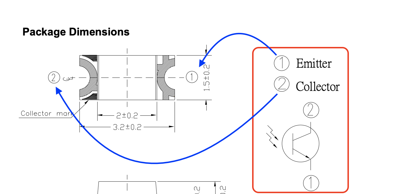
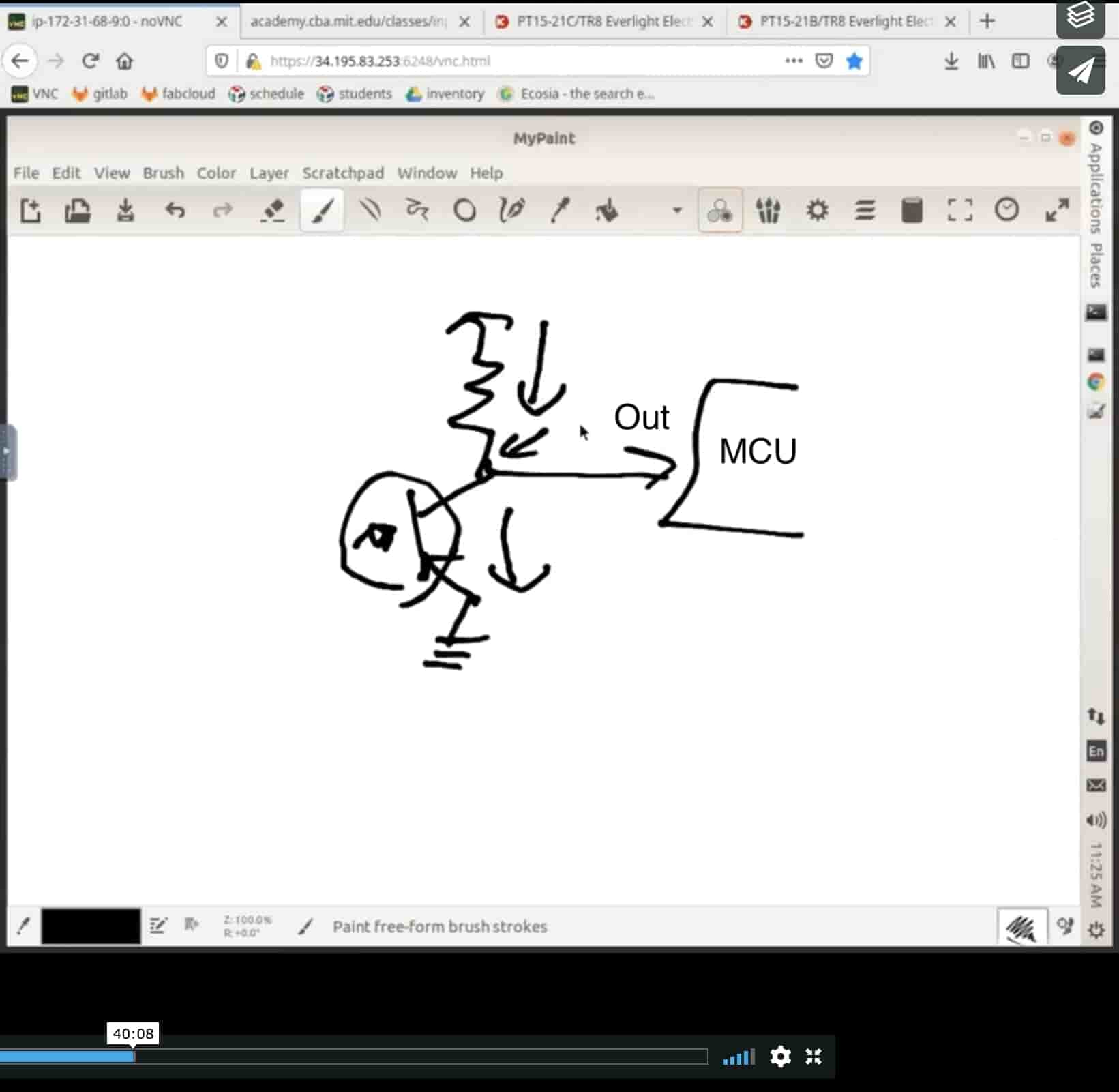
To spice things up, I will add a phototransistor to sense the amount of the light falling on it, dealing with this small device is pretty simple, it has only two terminals, an Emitter and Collector. It has no base terminal since it takes it’s input from the surrounding light. And here’s how to wire it with your microcontroller.
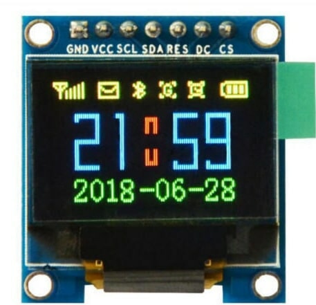
Also I will add a 7-pin connector header on the PCB so I connect an OLED screen on it to display the sensor reading. Which is communicating with the microcontroller over the SPI protocol.
In the datasheet of the ATmeag328P microcontroller, we can find the pinout of the microcontroller and each pin description. That's very important when we start connecting the sensor and the OLED screen to the microcontroller.
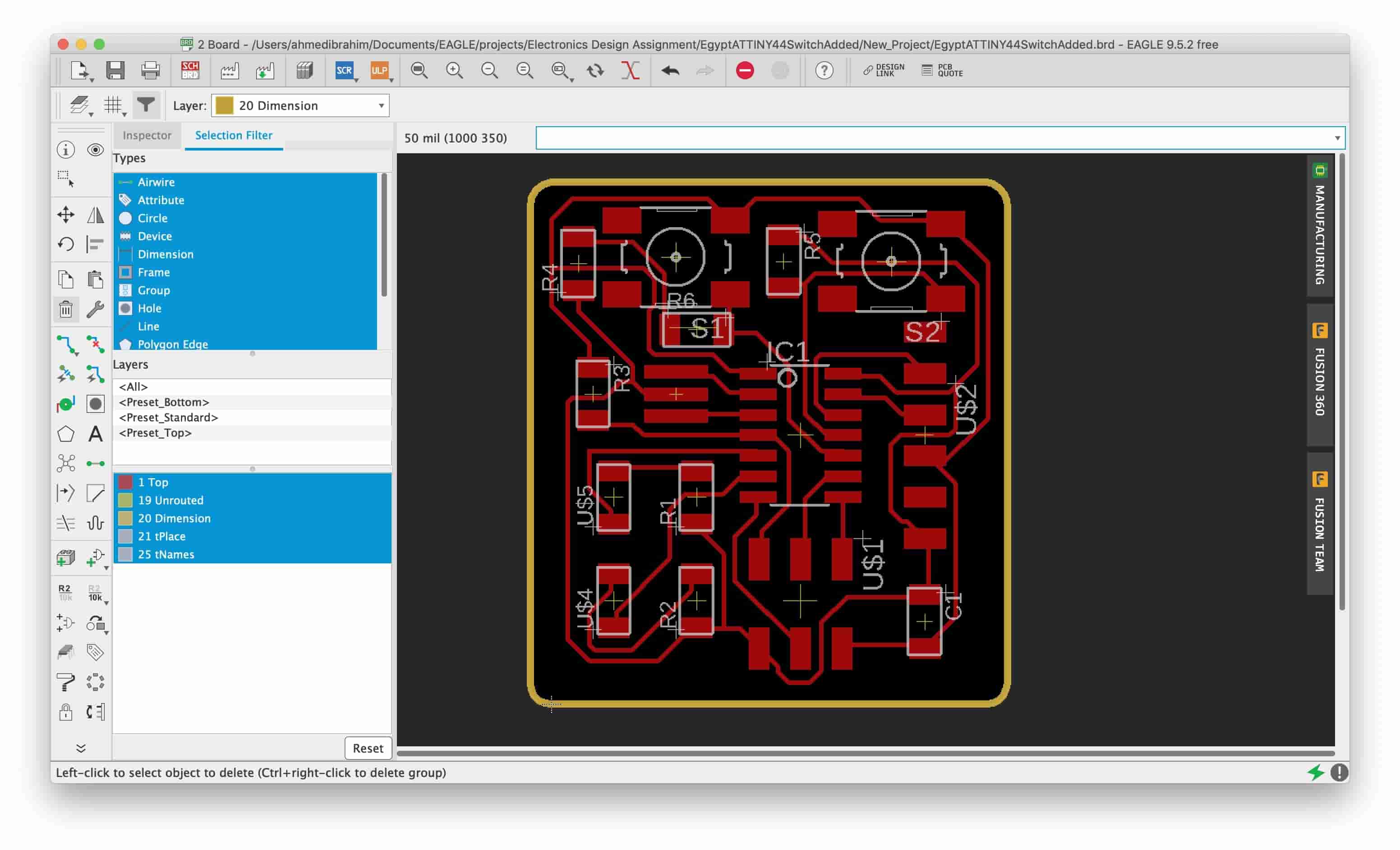
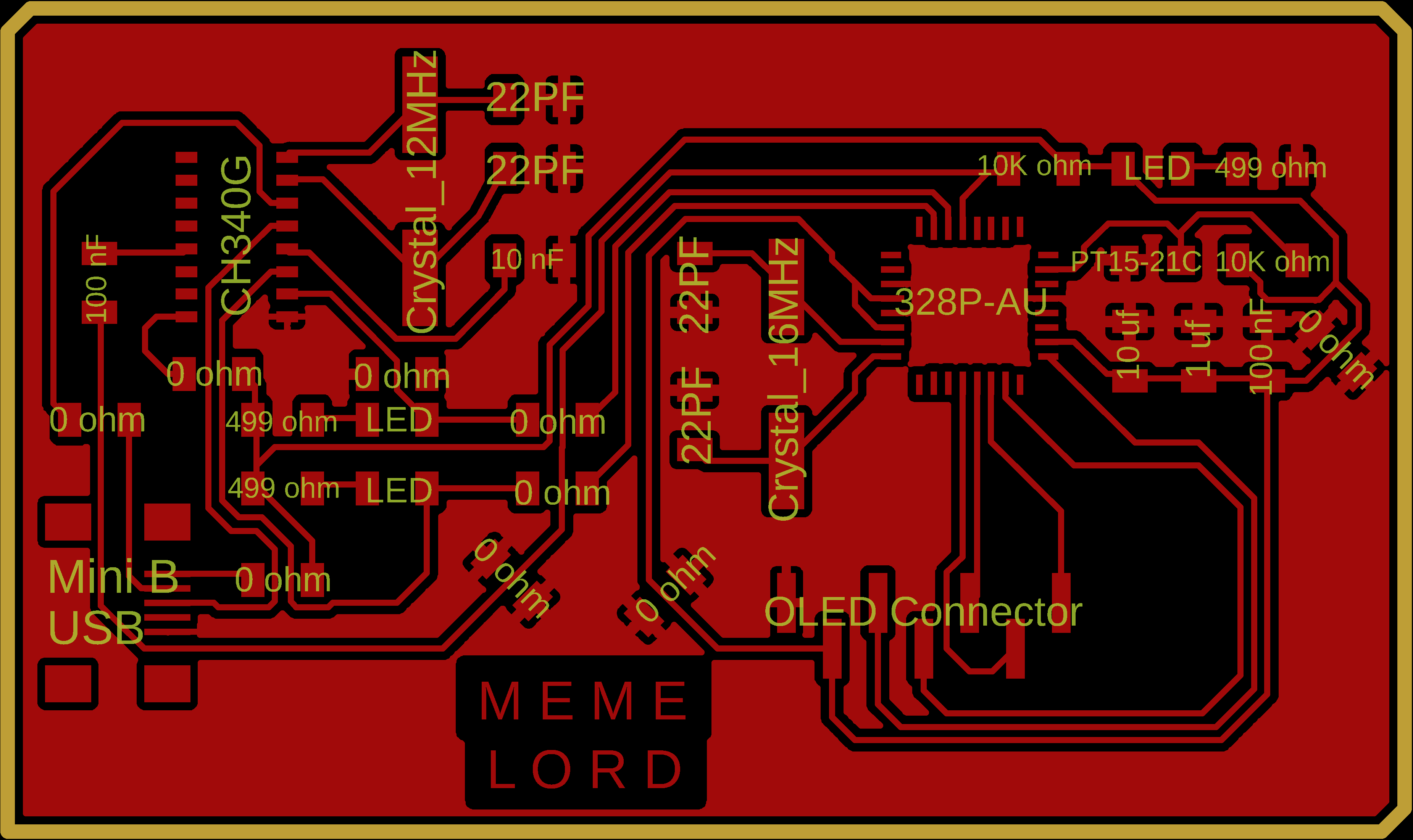
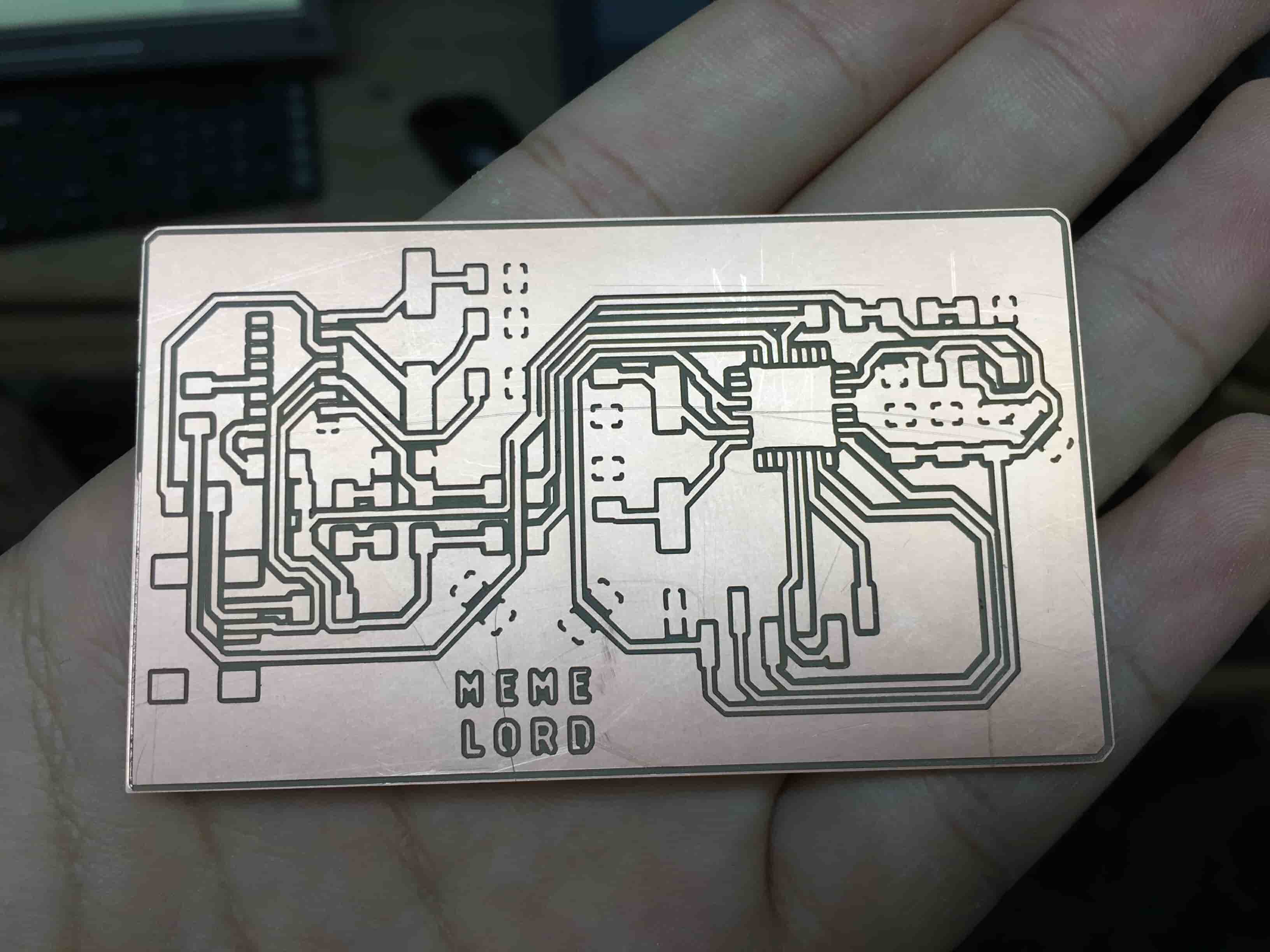
Now, I have all the important information I need to start designing my board. I opened my loyal friend, Eagle. And started with the circuit schematic, the CH340G IC is not found in the fab library, but it exists in the Sparkfun-IC library. After I finished the circuit schematic, I converted to the board layout. And here’s the result! If you want more details about the PCB designing, you can check my Electronics Design Week.
After that, I exported the fabrication files that I will send to my lovely Modela machine. If you want to know more information about how to export the PCB fabrication files and the post-processing work, you can check my Electronics Production Week and the Electronics Design Week.

PCB PNG Files Download
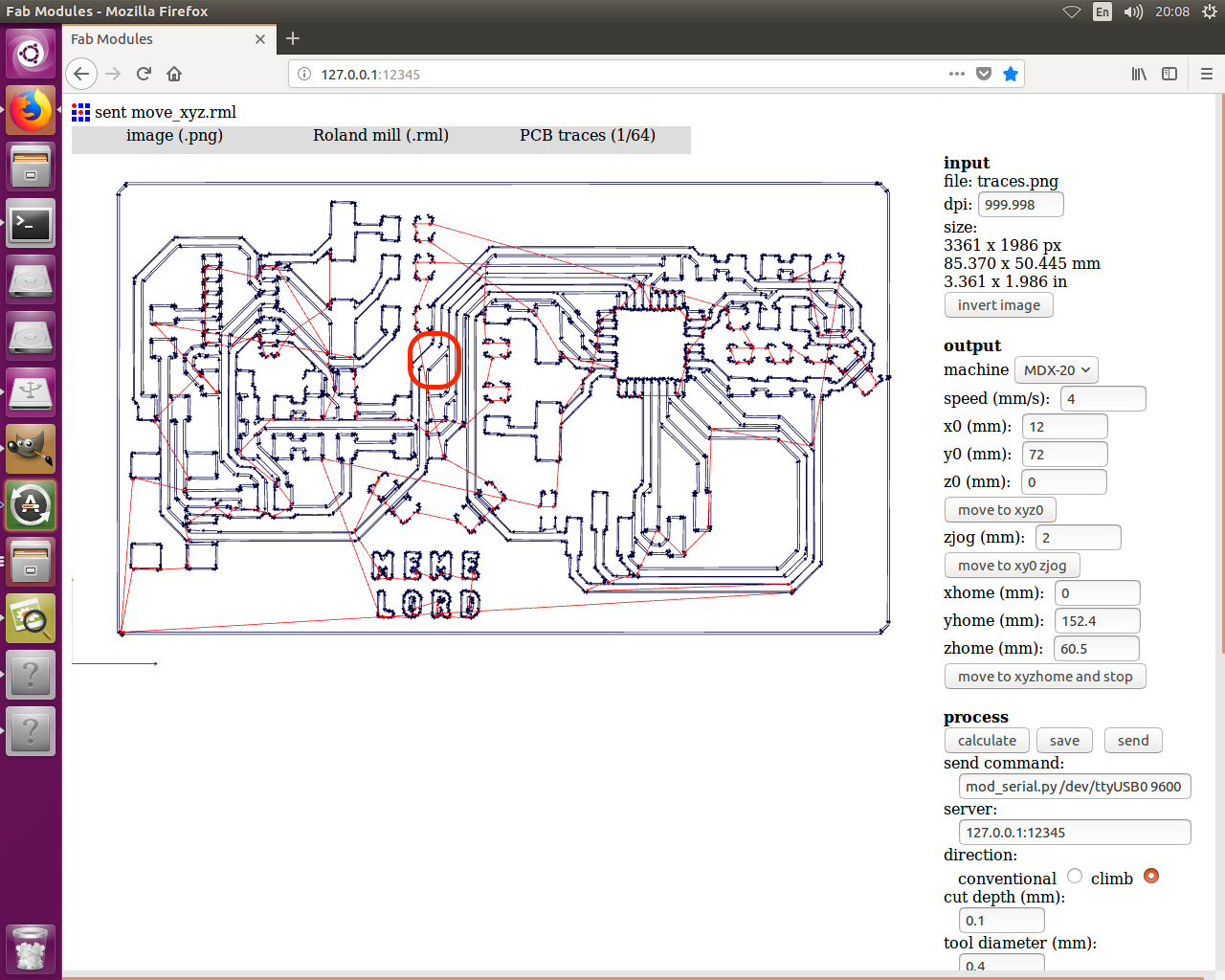
I imported the top traces PNG image to Fab Modules, setting all the parameters, and calculated the generated toolpath. After reviewing the generated toolpath and making sure that all the traces will get cut, I noticed a small short circuit between two traces, But, no problem I will cut them with a cutter later. Lastly, I sent the job file to the machine.
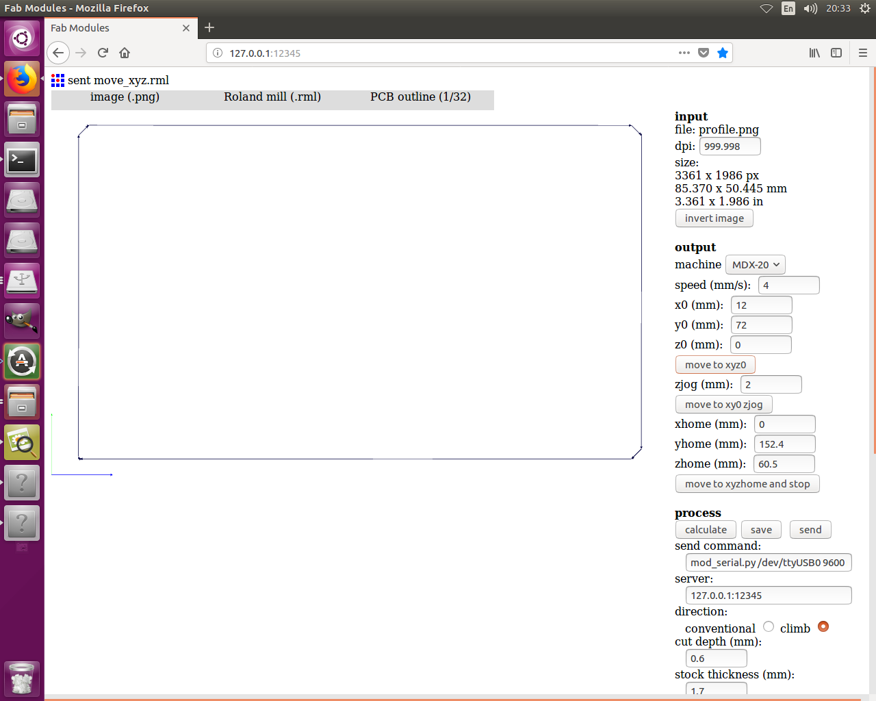
I made the same previous steps with the outline of the board, importing the profile PNG image, calculating the toolpath, and sending the job file to the machine.
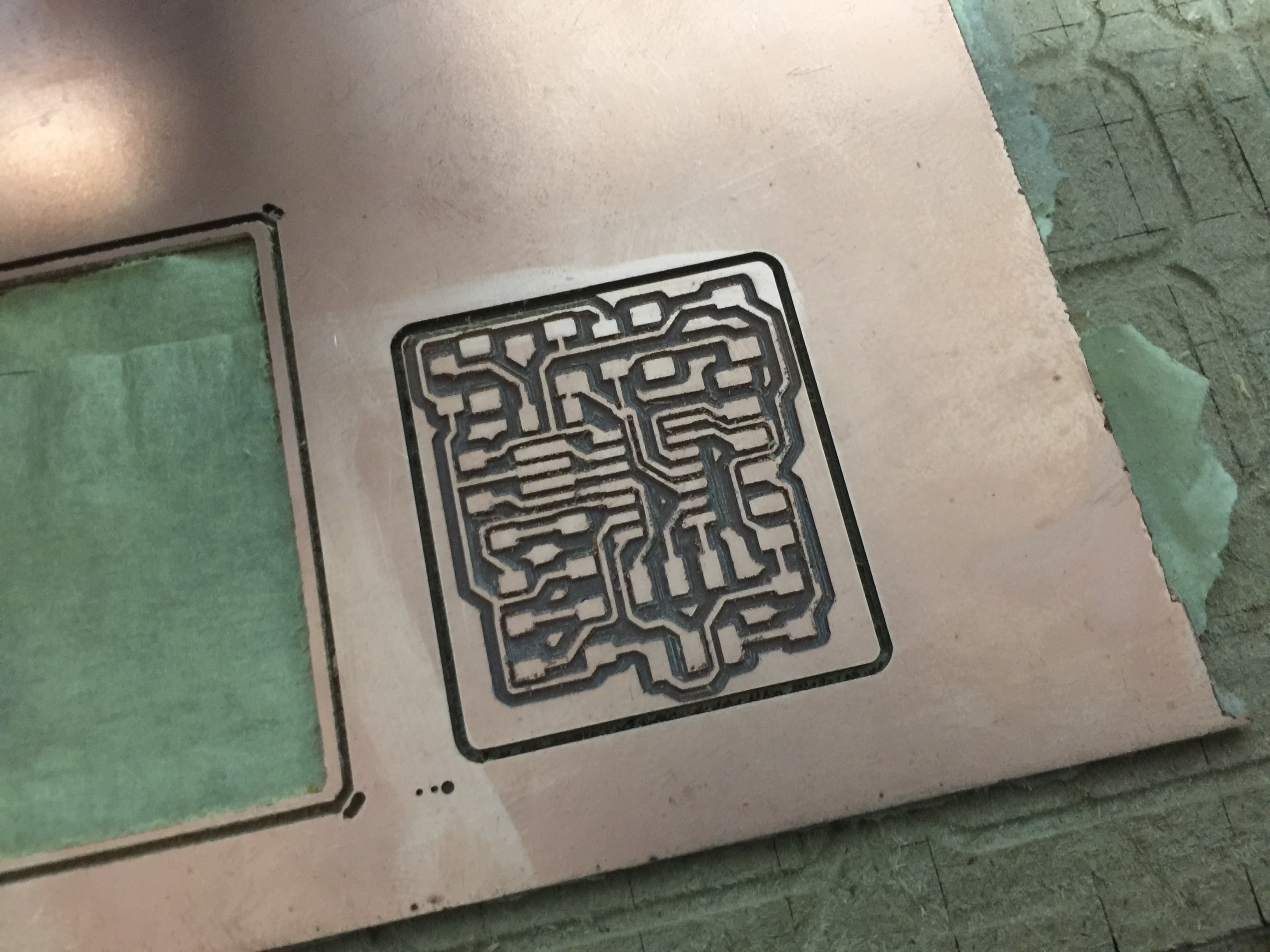
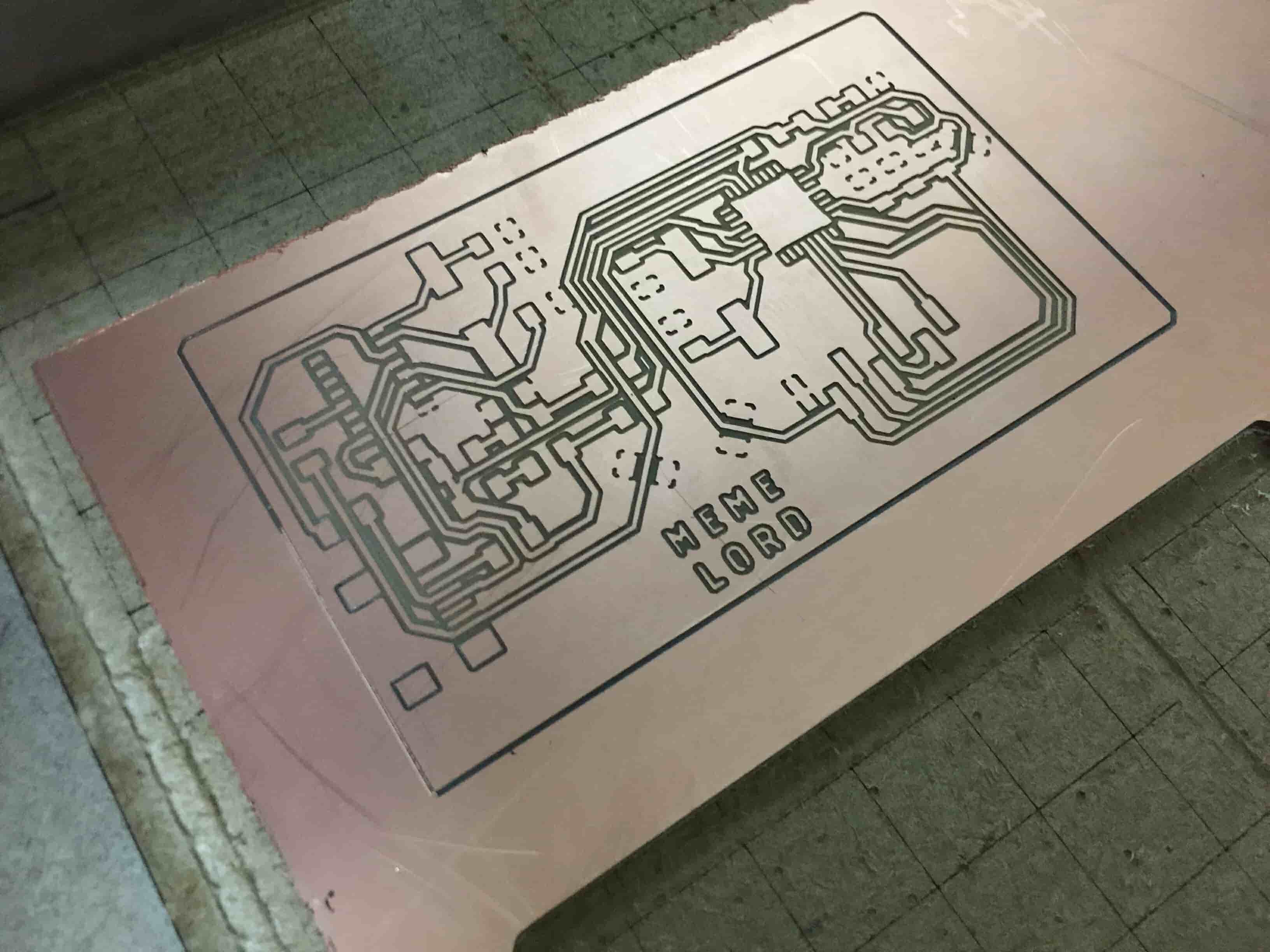
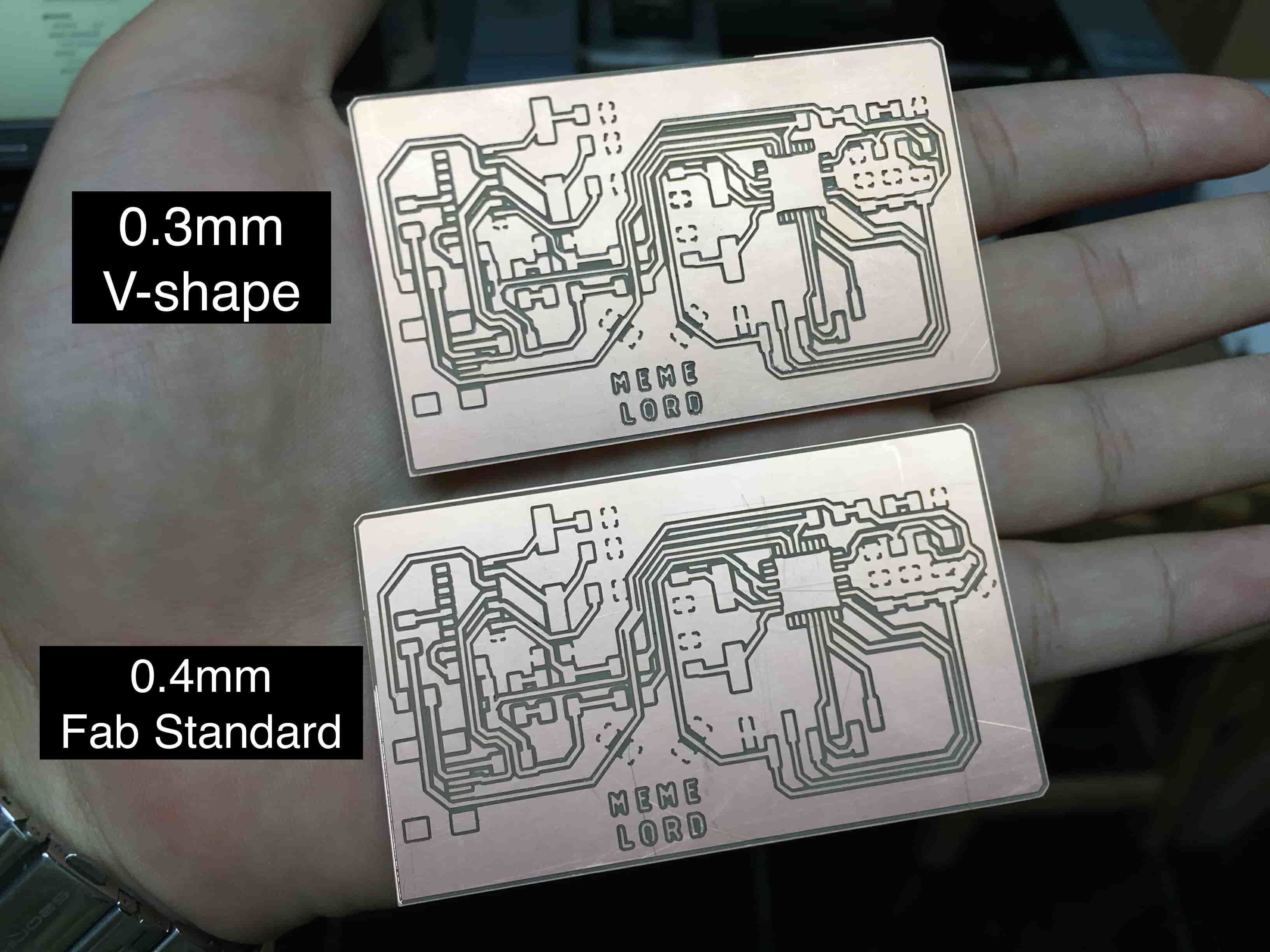
I never used a V-shape end mill before, I wanna know what is the difference between the V-shape end mill and the flat end mill(fab standard). This time, I fabricated my board two times, one using a 0.3mm V-shape end mill and the other one I used a 0.4mm flat end mill(fab standard). When using a V-shape end mill, the Z-axis depth becomes crucial because the width of the end mill varies based on depth. It seems that I didn’t adjust the end mill Z-axis depth right, because there are a lot of pads that have disappeared, specially the ATmega328P pads.
But the board that I used the 0.4mm flat end mill(1/64inch fab standard) with it went great! Ok, of course I will use this one :D
It’s time for soldering, I prepared all the components that I need and started soldering my board.
| Part Number | Description | Quantity | Supplier |
|---|---|---|---|
| ATMEGA328P-AU-ND | IC MCU 8BIT 32KB FLASH 32TQFP | 1 | digikey |
| 2395958 | 16Mhz/18pF SMD 11.4 x 4.7 mm crystal | 1 | Farnell |
| 1898660 | 12Mhz/18pF SMD 11.4 x 4.65 mm crystal | 1 | Farnell |
| H2961CT-ND | CONN RECEPT MINI USB2.0 5POS | 1 | digikey |
| CH340G IC | CH340G | 1 | Ali Baba |
| 445-1423-1-ND | CAP CER 1UF 50V X7R 10% 1206- | 1 | digikey |
| 587-1352-1-ND | CAP CER 10UF 35V Y5V 1206- | 1 | digikey |
| 399-4674-1-ND | CAP CERAMIC .1UF 250V X7R 1206-(100nf = 0.1uf) | 2 | digikey |
| 2984995 | SMD Multilayer Ceramic Capacitor, 22 pF, 10 V, 1206 | 4 | Farnell |
| 311-1174-1-ND | CAP 10000PF 50V CERAMIC X7R 1206 $0.03360-(10000pf = 10nf) | 1 | digikey |
| 311-10.0KFRCT-ND | RES 10.0K OHM 1-4W 1% 1206 SMD | 2 | digikey |
| 311-499FRCT-ND | RES 499 OHM 1-4W 1% 1206 SMD- | 3 | digikey |
| 311-0.0ERCT-ND | RES 0 OHM 1-4W 1% 1206 SMD | 9 | digikey |
| 1080-1380-1-ND | PT15-21C/TR8 | 1 | digikey |
| SSD1331 Color OLED Screen 0.95inch | Color OLED Screen 0.95' | 1 | Ali Baba |
| 160-1403-1-ND | LED YELLOW ORANGE CLEAR 1206 SMD | 1 | digikey |
| 160-1737-1-ND | LED WHITE YELLOW 260MCD 1206 | 1 | digikey |
| 160-1889-1-ND | LED BLUE CLEAR 1206 REV MT SMD | 1 | digikey |
| S1013E-36-ND | CONN HEADER SMD 30POS 2.54MM | 1 | digikey |
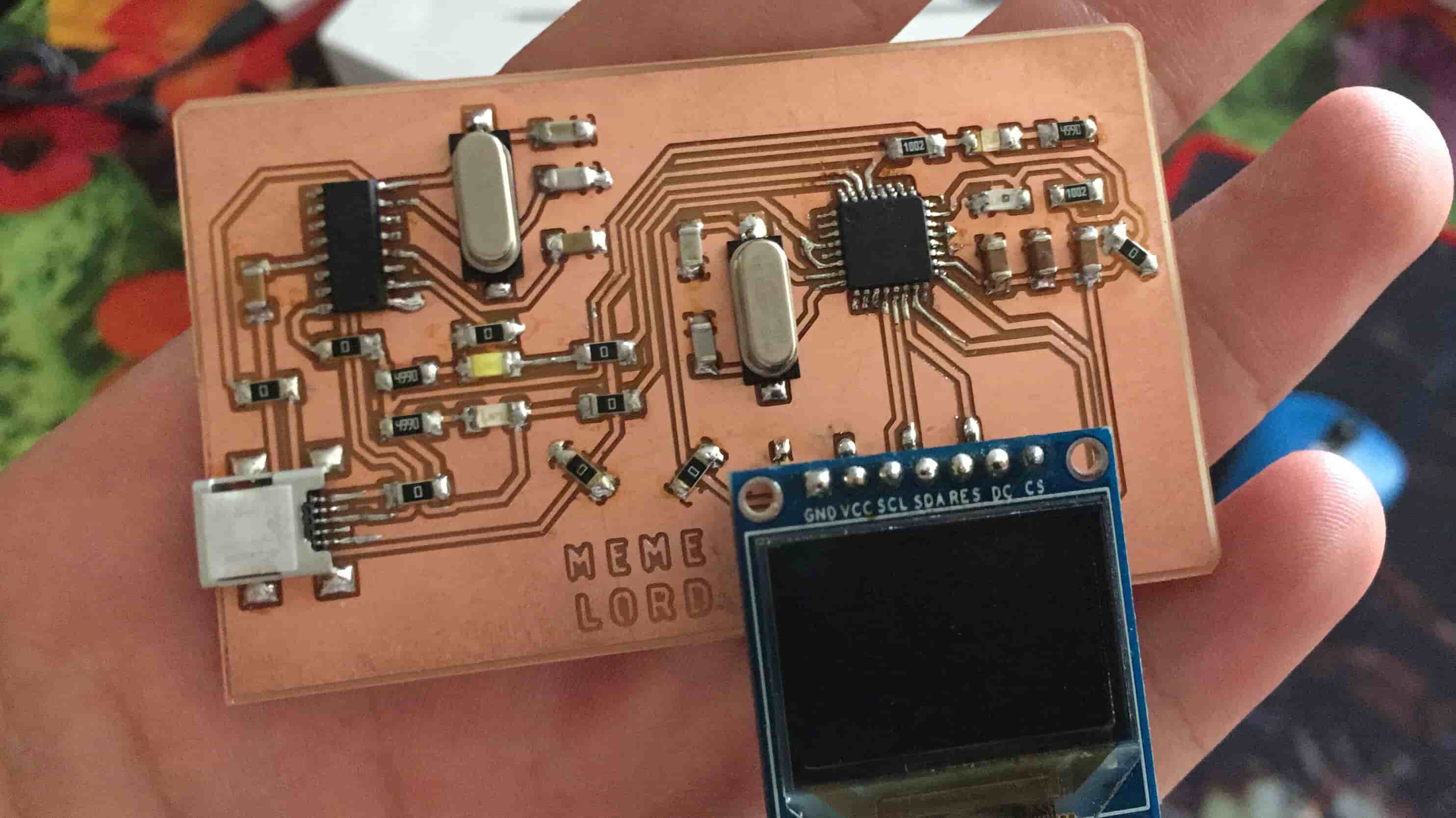
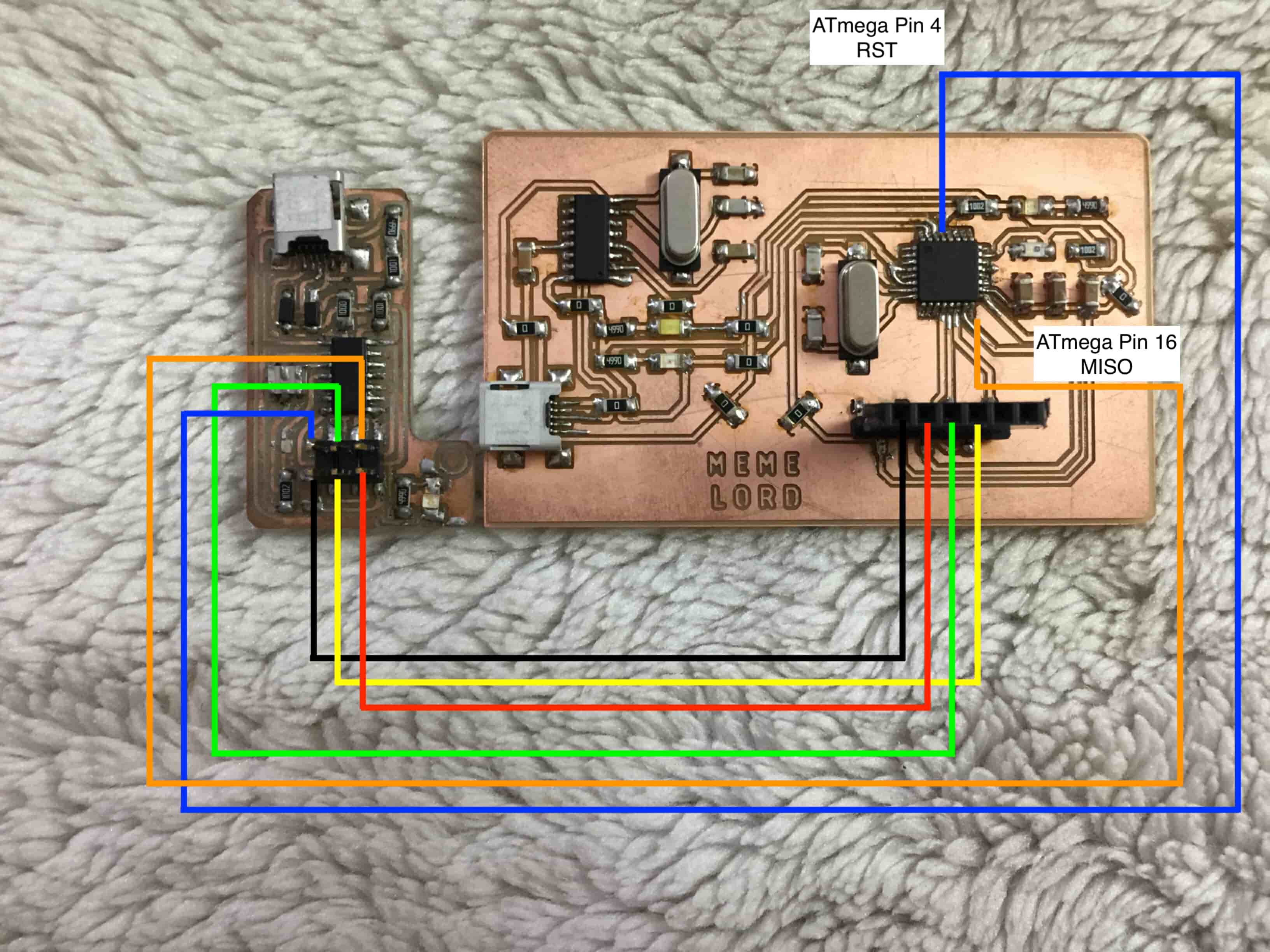
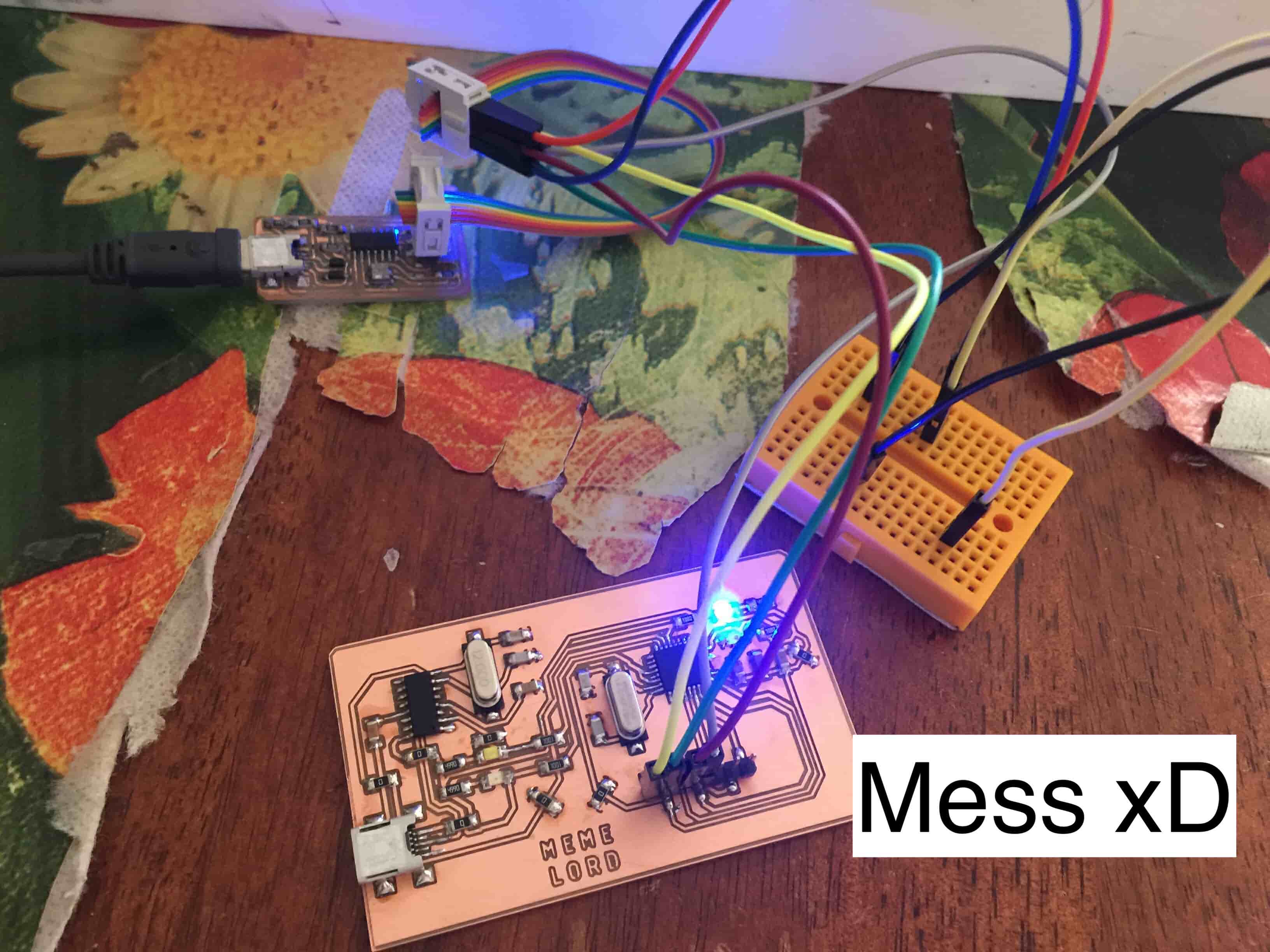
We are ready to test that masterpiece. First, we need to upload the Arduino UNO bootloader to the ATmega328P chip. To do that, we need an external programmer. I used the programmer I made in the Electronics Production Week to upload the bootloader to the chip. But, where is the AVR ISP header? I can’t see it on the board! Actually,I chose to save some space and don’t put the AVR ISP header on the board since I’m already exposing almost all of the SPI protocol pins on the OLED screen header connector,
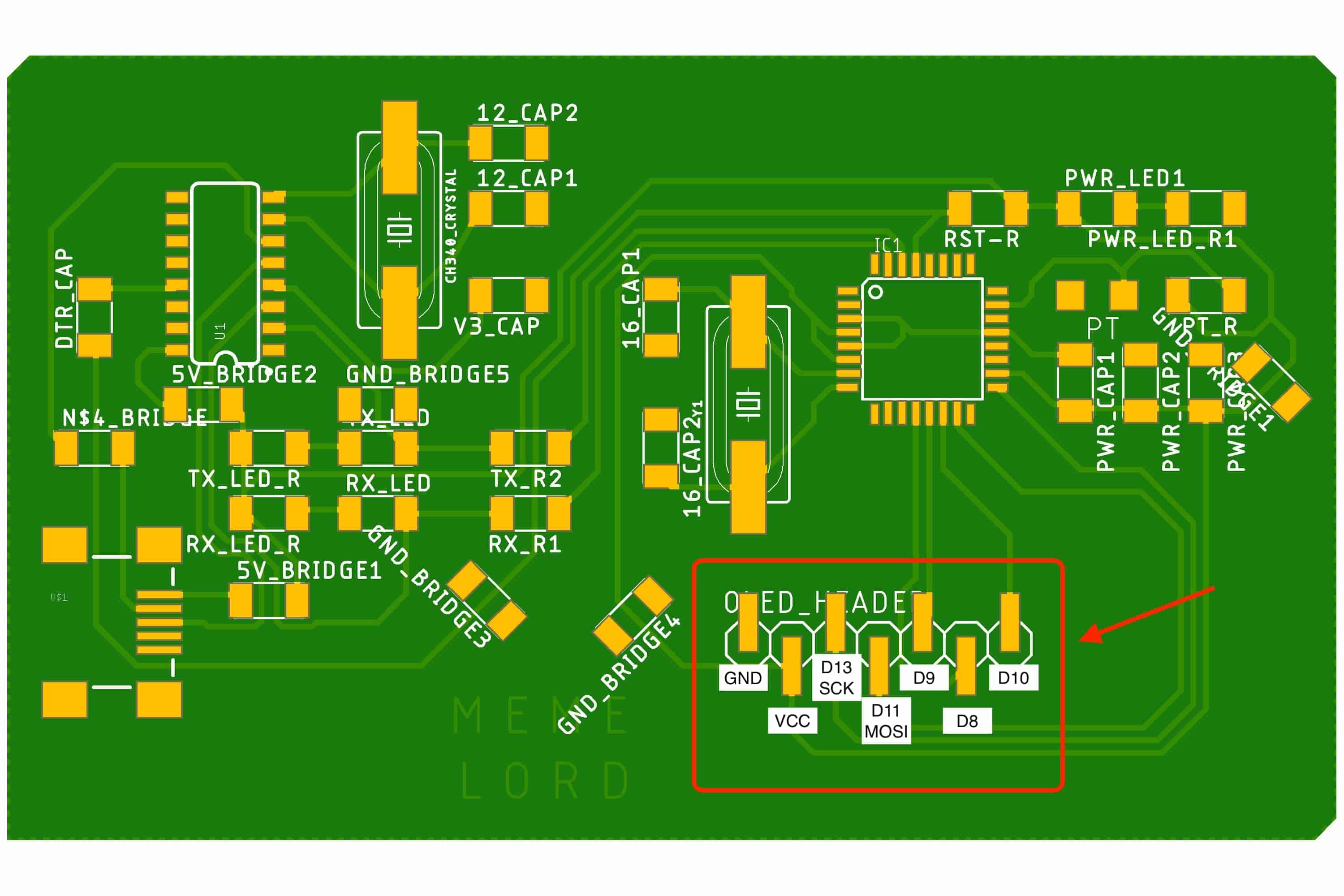
The programmer needs 6-pin to communicate with the target(VCC, GND, MOSI, MISO, SCK, Reset) We have only four of them exists on the ATmega328P board(VCC, GND, MOSI, SCK). I will connect the reset and MISO pins manually by two jumpers.
It’s the time to upload the bootloader to the chip.After setting all the shown parameters, click on “Burn Bootloader”. That’s it!
I wrote a simple program to test that the OLED screen is working fine. Sparkfun has uploaded on Github a wonderful open-source library that can draw pixels, lines, rectangles, circles, text and bitmaps as well as example code you can check em out from this link, also there’s a good tutorial talking about the Adafruit_GFX library that I’m using in my code.
After getting sure that the OLED screen is working fine, I want to write a C program that reads the phototransistor input value and display it on the OLED screen. The phototransistor is connected on pin A0(PC0). By using the analogRead() function we are activating the ADC to read the input data coming from the phototransistor and convert it into a digital value (0-1023), then we take this value and map it using the map() function into a value between 0-80 which will be used after to set the rectangle width that we will draw on the OLED screen.
The Meme Lord board with Python and Tkinter
Now, I wanna write a Python GUI program that controls the OLED screen background color, text color, and some other screen displaying stuff. The meme lord board and the Python GUI are connected and talking to each other via the Serial port. I will use the famous Tkinter python module to build my GUI program. And to establish the Serial communication between the GUI and the ATmega board we are gonna use the PySerial module. To be able to use the Serial communication with Python you have to install the PySerial library, it doesn’t come by default with Python. Here’s a link showing how to install PySerial. And here’s a link too showing how to install Tkinter in case you don’t have it on your machine.
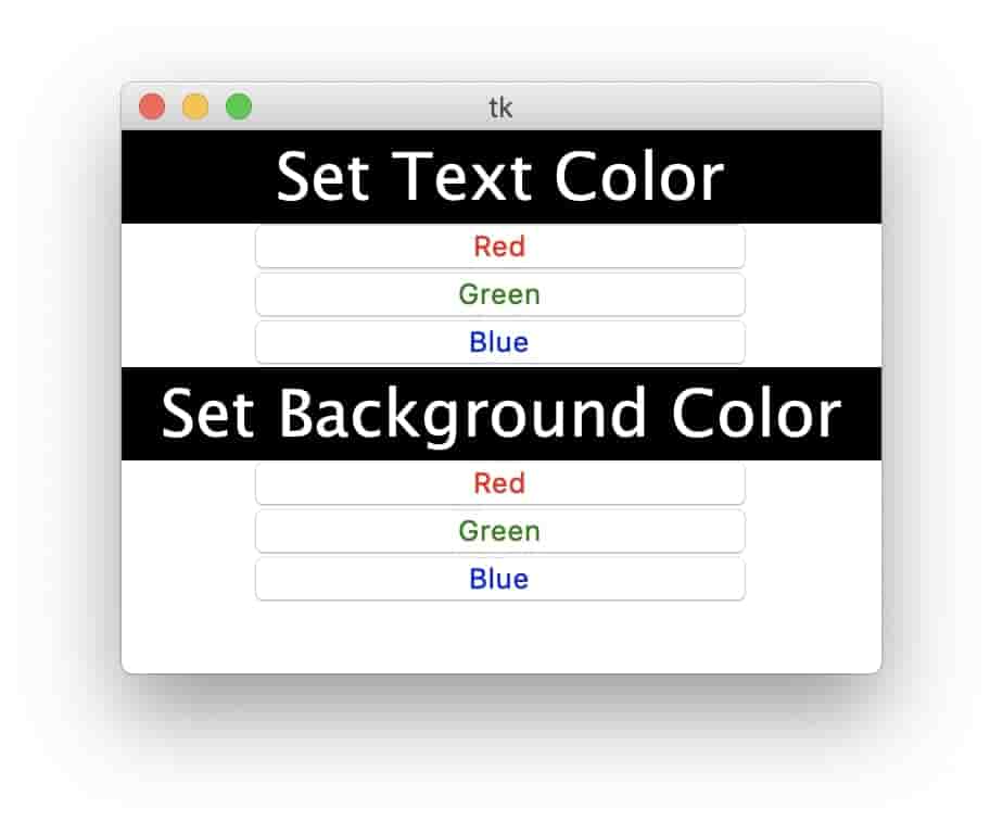
I like to divide my program into sub-programs and finish each sub-program individually to make the debugging process easier. And after finishing all the sub-program and making sure that everything is working correctly, I merge them all in one program. So, the first step is to build the app GUI and test that all the buttons are working correctly without problems before writing any Serial communication code. I designed a simple GUI, it has two labels and six buttons. Three buttons for selecting the background color,and another Three buttons for selecting the text color.
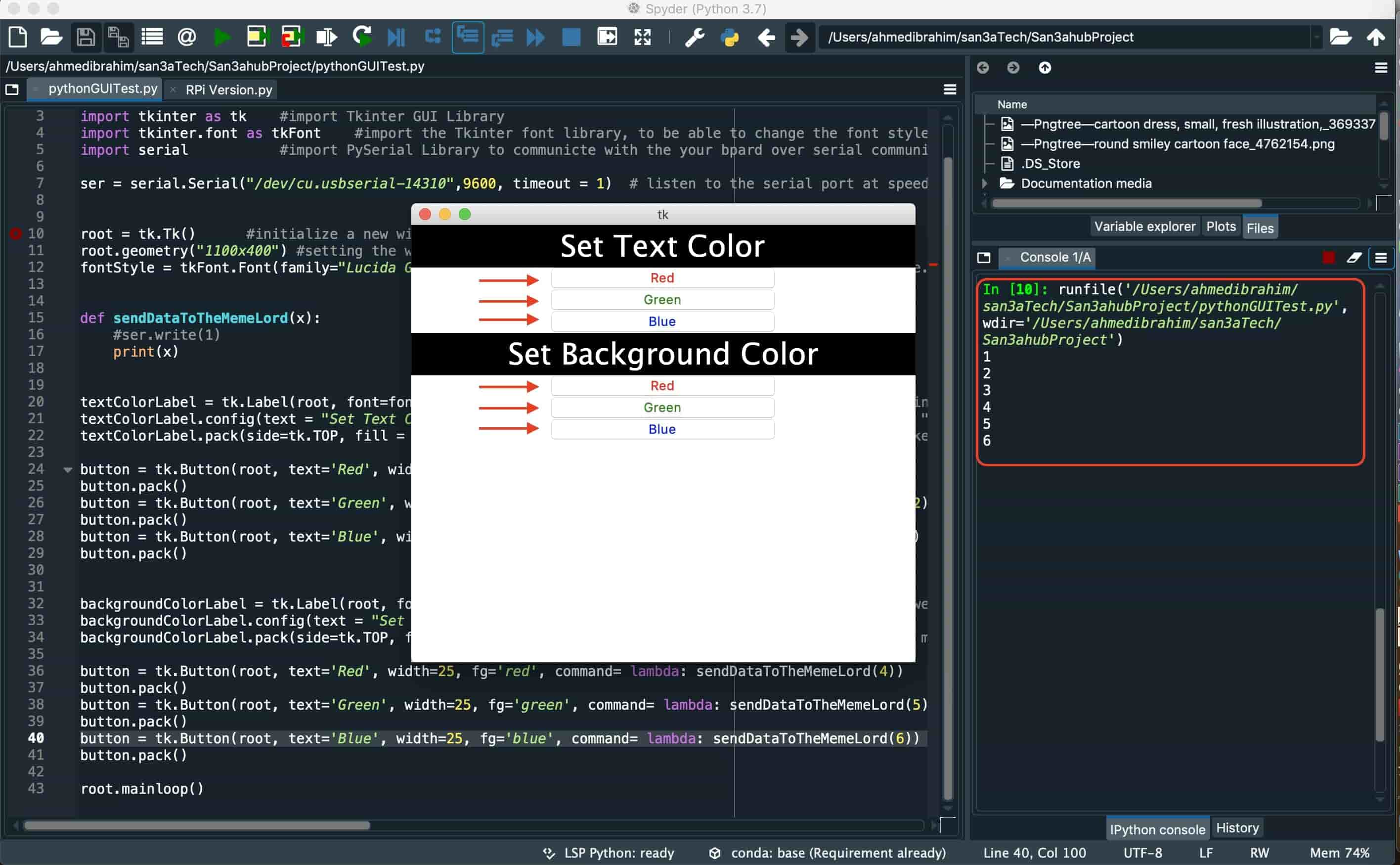
When I press any button from the six buttons, it triggers the sendDataToTheMemeLord(x) which takes one argument x, this argument x is the data that will be sent to the ATmega board over the Serial port. Each button passes a different value to the sendDataToTheMemeLord(x) argument. Words are great! but we need to test that script if it’s working or not, So I told my script when I press any button from these six buttons, print the data which the pressed button passed to the sendDataToTheMemeLord(x) function on the terminal. And that went great!
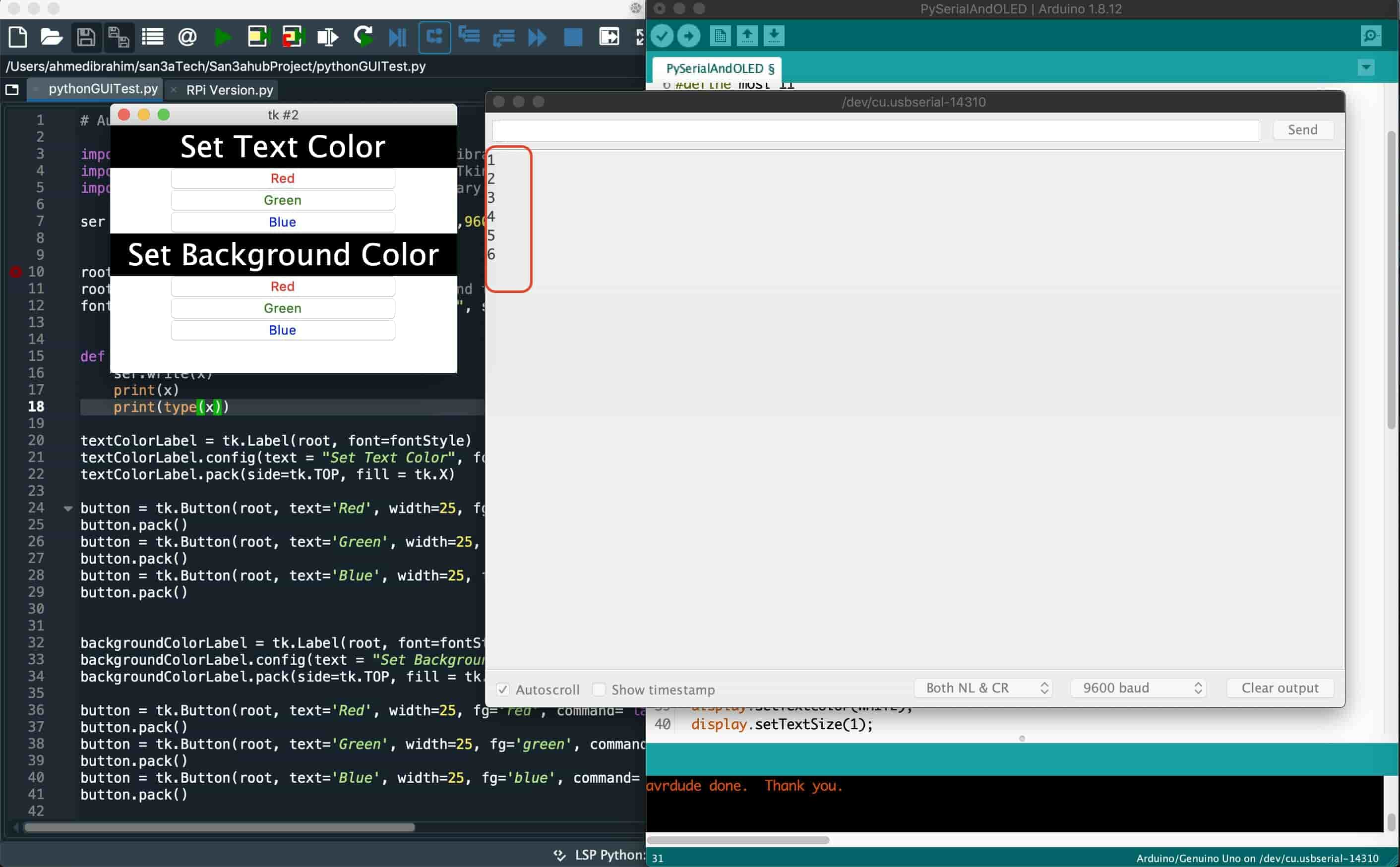
The next step is to send that data to the Meme Lord board over the Serial port. As I stated before, I’m using the PySerial module to establish a serial communication between the Python GUI app and the Meme Lord board. After the Meme lord board receives that data it will change the colors of the screen background and text color accordingly. But first, I wanna make sure that the data is traveling from the Python GUI to the Meme Lord board correctly without problems. So, in the Python code i’m using the PySerial .write() function to send a one byte char to the Meme Lord board over the Serial port. And in the C code, I’m reading that one byte data and printing it in the Arduino Serial monitor. And it went great again!
We are up to the final part of this project, the Meme Lord board now is receiving the data from the Python GUI app correctly, right! Let's take some actions tho. We will slightly modify our C code by adding a switch case that checks what are the data coming from the python app, according to the received data it will take different actions like setting the background color or the text color to black or green or blue.
Programming in Embedded C and AVRDUDE
Before doing any type of programming we need to set our toolchain, since I’m using a MAC machine, I’m using the AVR crosspack development environment that comes with the GNU compiler suite, a C library for the AVR, the AVRDUDE uploader and several other
useful tools.
Setting the Makefile is like a nightmare for me! Let’s try to understand together the main fuses that we will need to set, hopefully! In all microcontrollers you must have some way to permanently control some parameters that do not change with the power cut off from the microcontroller. Like the clock speed, JTAG enabling or disabling, SPI enabling or disabling, and you can disable reprogramming the chip permanently(it’s dangerous!). So, Be careful when experimenting with fuses as I ruined one of my boards.
The microcontroller Fuses are divided into three categories:
- Low Fuse Byte
- High Fuse Byte
- Extended Fuse Byte.
Each of The Low Fuse Byte and High Fuse Byte contains 8 bits, each bit controls a specific feature or parameter inside the chip, we can activate and deactivate this feature by setting this fuse to either “Programmed(0)” or “Not Programmed(1)”. I know you are confused, fuse bits – oddly enough – 1=unprogrammed and 0=programmed. We will focus today on the first two categories only(Low Fuse Byte, High Fuse Byte). We will not need the Extended Fuse Byte.
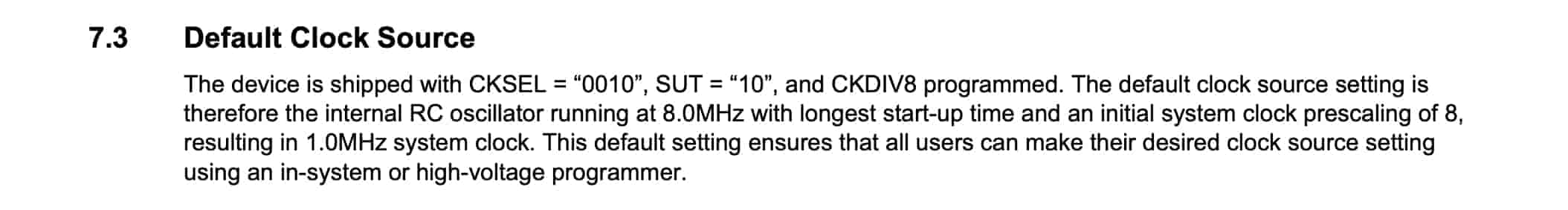
Let's set the chip clock speed fuses, The ATTiny44a chip comes from the factory with some default settings, like the default clock source that is mentioned in the datasheet. But, we need to set the fuses to match the 20MHz resonator that I’m using in my board.
Datasheet is your friend, I opened the Attiny44A datasheet and it’s stating that there are different options that we can choose from by setting the fuse bits. This table is demonstrating the different options and how to set the fuse bits. It says, if you are using an external crystal or resonator as the chip clock source, you need to set the CKSEL(3, 2, 1, 0) - Clock select to 1000(if crystal is used) or 1111(if ceramic resonator is used). But wait, that's very general information, we need more details about the external clock source frequency speed and it’s fuse bits. (Remember, 1=unprogrammed, 0=programmed).
- CKSEL(3, 2, 1, 0) - Clock select: those four bits are responsible for selecting the frequency of the chip clock source. From the datasheet we can see how to set those four bits fuses according to the used clock frequency
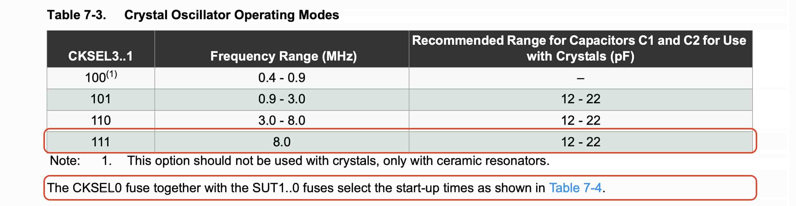
The previous table is stating that, if you are using an external clock source(crystal or resonator) with frequency of 8MHz or more, you need to set the CKSEL(3, 2, 1) to 1(unprogrammed).
- SUT(1,0) - Start Up time: provide the delay at start up which is required for the oscillator to stabilize. It’s always a good idea to set that two bits(SUT1, SUT0) on slowly rising power when you are using a high frequency resonator.
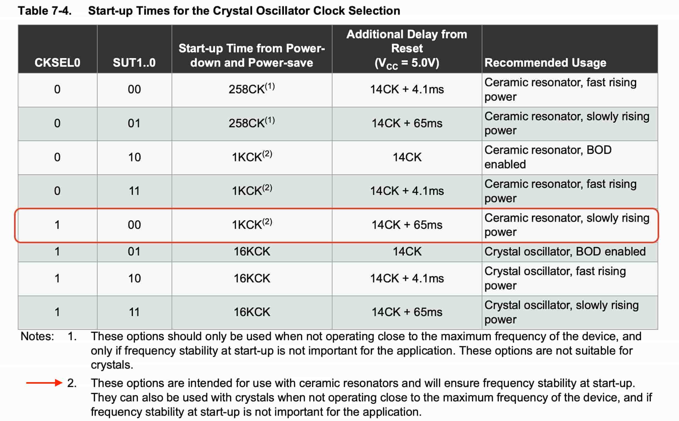
This table is stating that, if you need to give more stability to your resonator when the chip is booting up, set the CKSEL0 to 1(unprogrammed), and the SUT(1, 0) to 0(programmed)
After we knew how to set the low fuses that are in general responsible for clock and frequencies. Let’s take a look at the High Byte Fuses that are responsible for the communication with memories (flash, EEPROM), with the bootloader, and with other devices via SPI.
Actually, I didn’t play too much in the High Byte Fuses. But, here’s a very very very important note that you should put in your consideration. The SPIEN fuse bit is responsible for enabling and disabling programming the chip over SPI, When the SPIEN fuse bit is programmed(=0), serial programming and data downloading is enabled. The default value for this fuse is programmed(=0). SPIEN bit is used to disable serial programming mode ISP so Never change SPIEN fuse. If you set this fuse bit to 1(unprogrammed) you will not be able to upload any code to the chip anymore. You can reset the fuses through the High Voltage Serial Programming (HVSP) interface, but usually replacing the chip is a cheaper and quicker method.
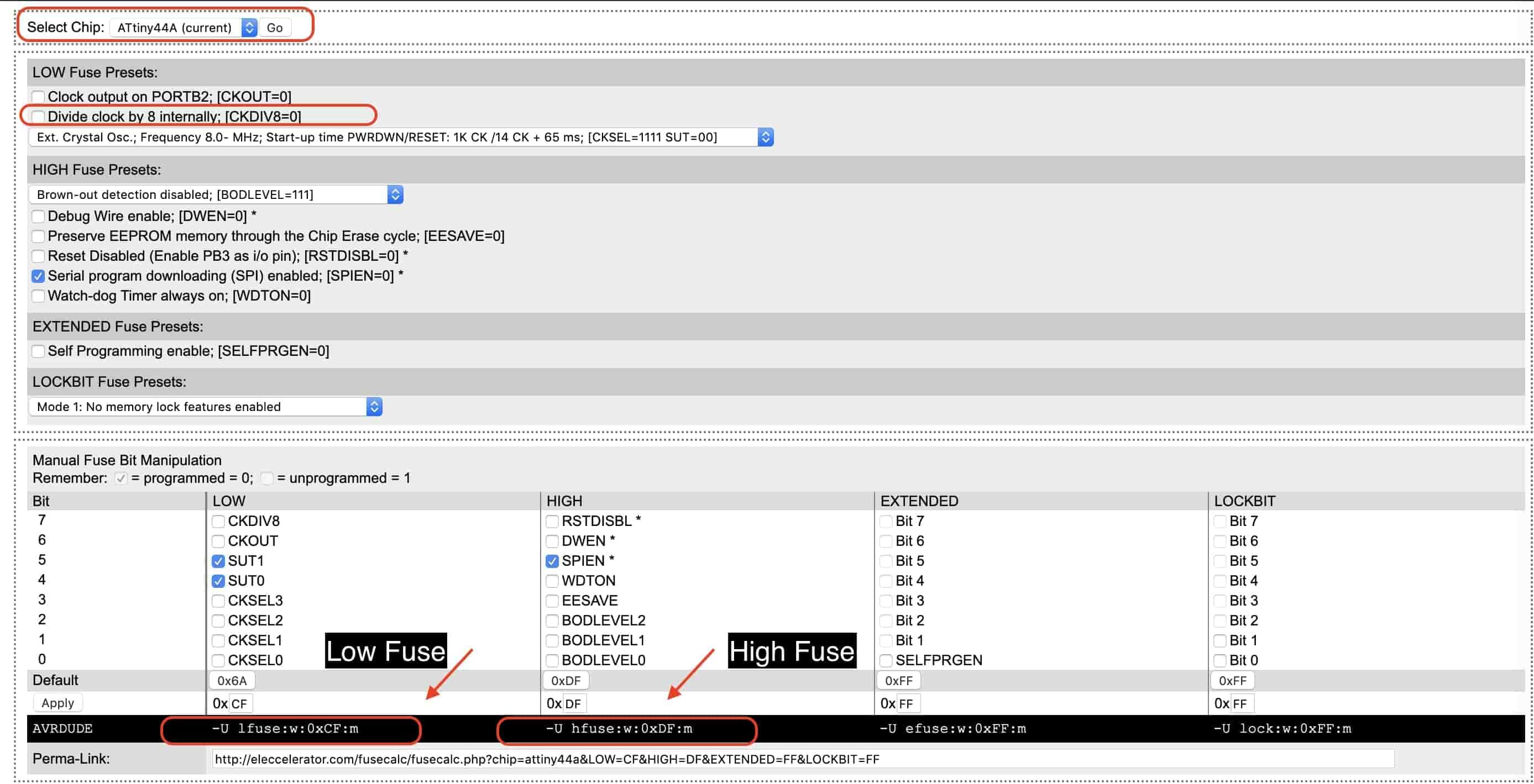
To wrap things up, I’m using a neat AVR fuses calculator that you choose the chip you are using then set each bit if it’s programmed(=0) or unprogrammed(=1) and this calculator tells you the high, low, extended fuses according to the parameters you set before. Here’s my final fuses.
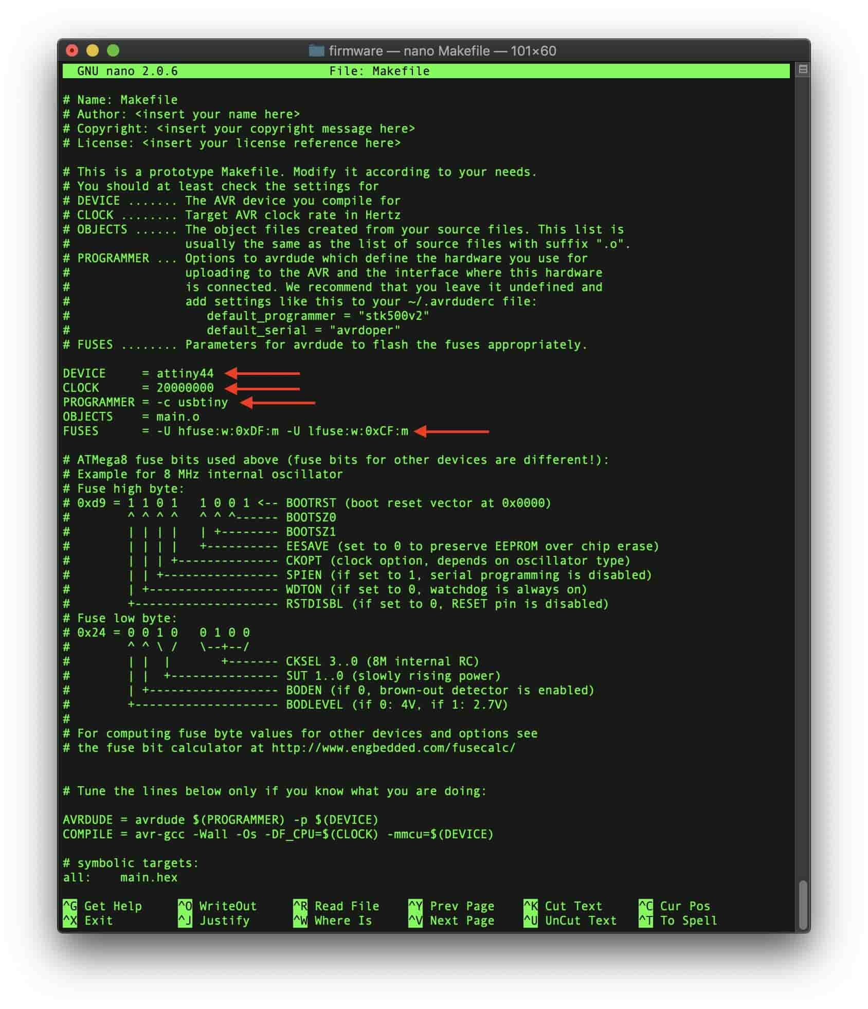
After that I edited my Makefile according to the new fuses.
Lastly I wrote a simple C code to test that everything is working fine and the fuses are set correctly. And it went great!
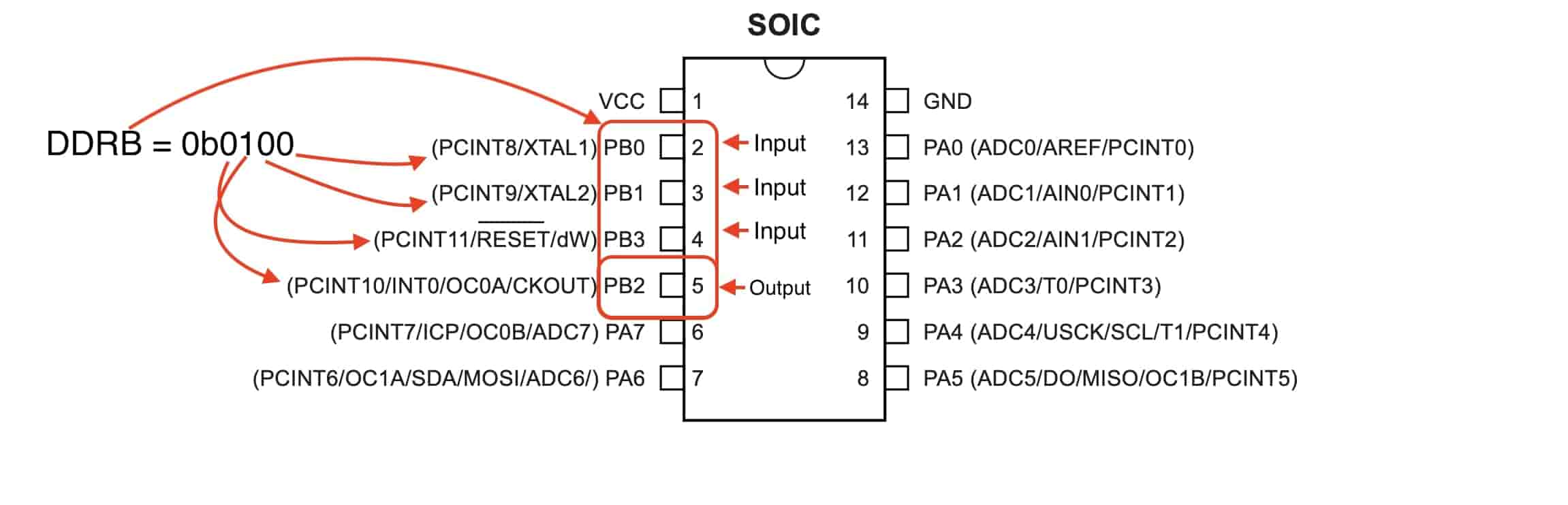
The code is very simple, DDRx (Data Direction Register) configures data direction of port pins. With this command we can set a specific AVR chip pin to be an input or output pin. By setting the bit to 1, the corresponding chip pin will be set to output. If we set the bit to 0, the AVR chip corresponding pin will be set to input.
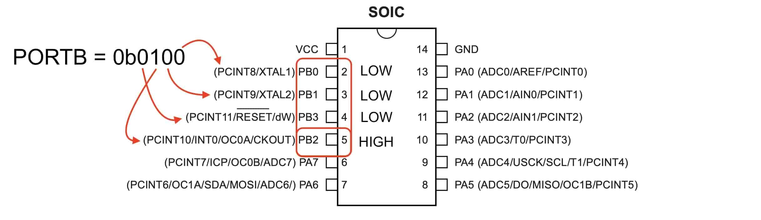
The PORTx register has two purposes, to output data(when port is configured as output). And to activate/deactivate the internal pull-up resistors(when port is configured as input).
Since we set the DDRx register bit to 1, corresponding pins become output pins, so we are configuring PORTx register bits to write data into respective pins in the PORTx register. For example, we are using PORTB = 0b0100; to tell the PB2 pin to output 5V(lights up the LED). and PORTB = 0b0000; to tell the PB2 pin to output 0V(turn off the LED)
Finally we are using the _delay_ms(1000); function to tell the program to wait 1000 milliseconds(1 second) when you reach this line.
We are blinking LEDs now that’s great! Let’s spice things up a lil bit. We need to read the push button input value and turn on the LED if the button is pressed. And turn it off if it’s not pressed. Simple!
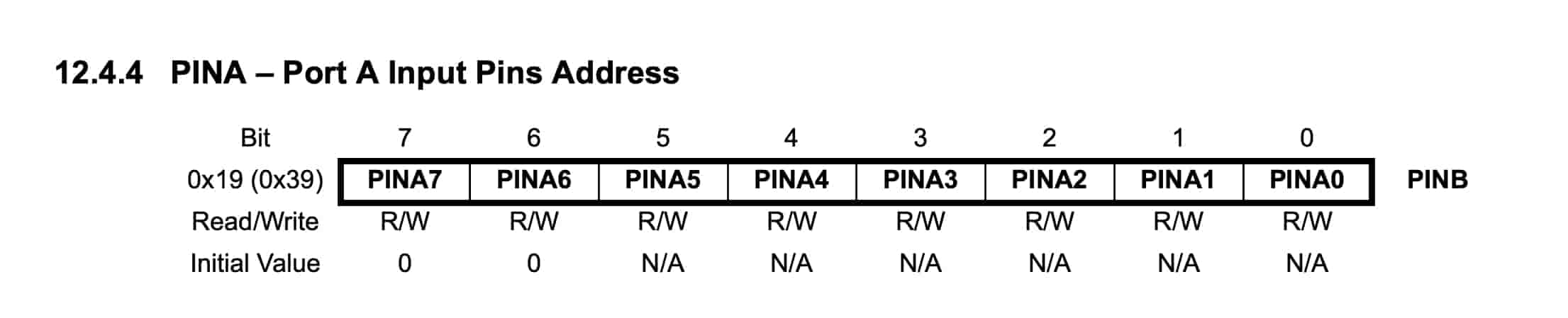
The microcontroller automatically reads the input voltage of all the GPIO pins and stores it inside the PINx byte(x represents the port name A, B, ... as we stated before). For example, the PINA register is reading all the port A GPIO pins input voltage value continuously. The PINA register contains 8 bits, each bit is representing the input reading of its corresponding pin. If the input reading is HIGH(5V) its corresponding bit will be equal to 1, If the input reading is LOW(0V) its corresponding bit will be equal to 0.
For example, if we applied 5V on the PA0, PA1, and PA2, the PINA register value will be equal to 0b00000111. If we applied 5V on all the port A pins, the PINA register value will be equal to 0b11111111.
In our code we are using an if condition to light up the LED(which is connected on the PB2 pin) if the push button (which is connected on the PA2 pin) is pressed(which means the PINA register byte value equals to 0b00000100). And, if the push button is not pressed(which means the PINA register byte value equals to 0b00000000), turn off the LED by configuring the PORTB bits to 0b0000.
Final
You reached this line?! Man, I love you for real.