Computer-Controlled Machining
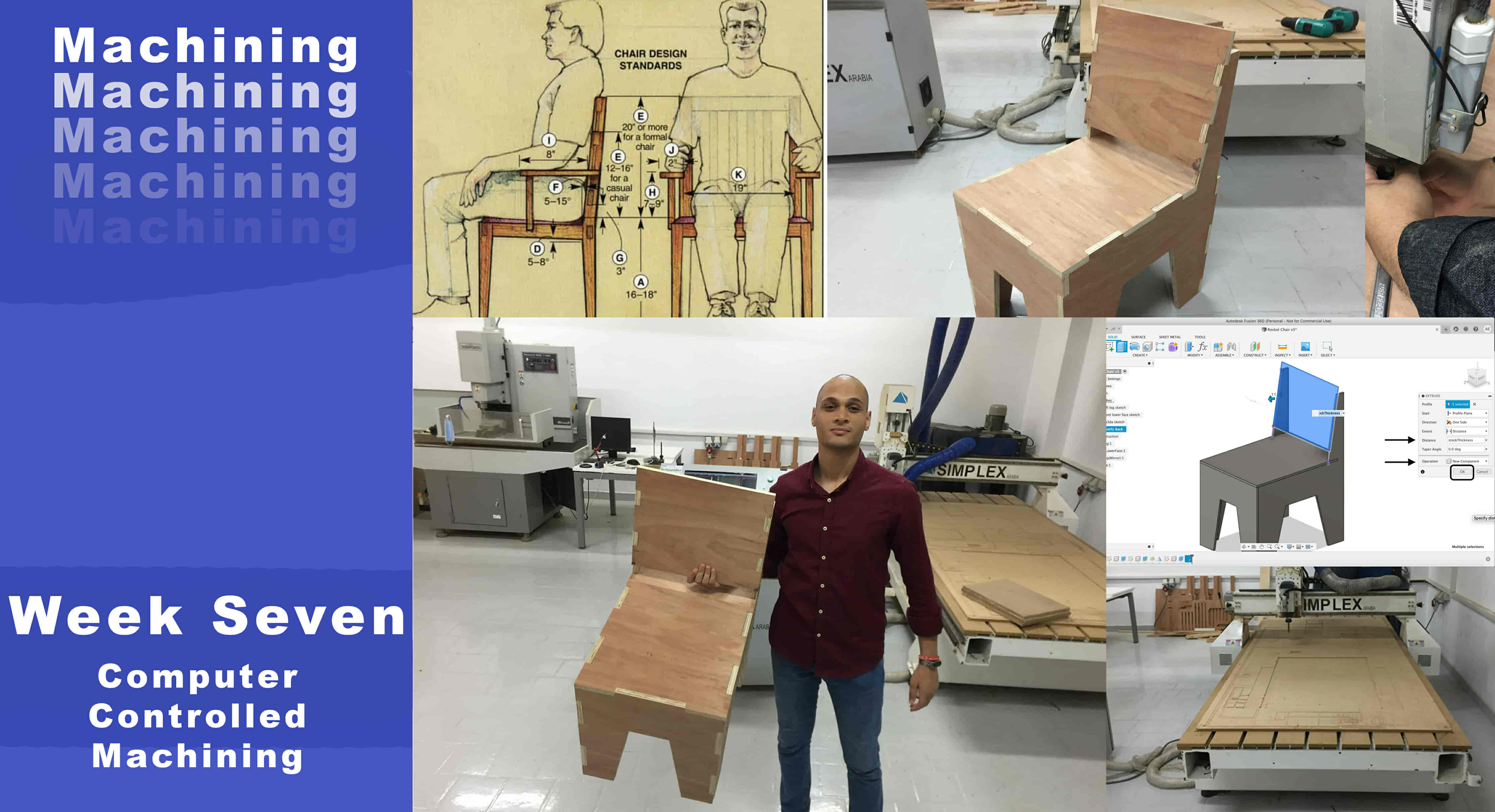
What’s Going on?
This week, we need to design and fabricate a big thing! I’m thinking about making a chair! The first thing that came to my mind what’s the dimensions and angles of this chair? I struggled at the beginning. But, I guess there is a standard or recommended dimensions/angles for the basic chairs. I searched online for the basic chair measurements and I found a lot of resources providing that data! They are providing the measurements/angles that guarantee maximum comfort! (According to them xD)
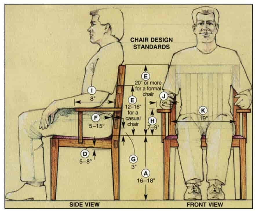
The first resource I found is this amazing article from the woodmagazine website. They are explaining each parameter and providing some amazing images to clarify their words.
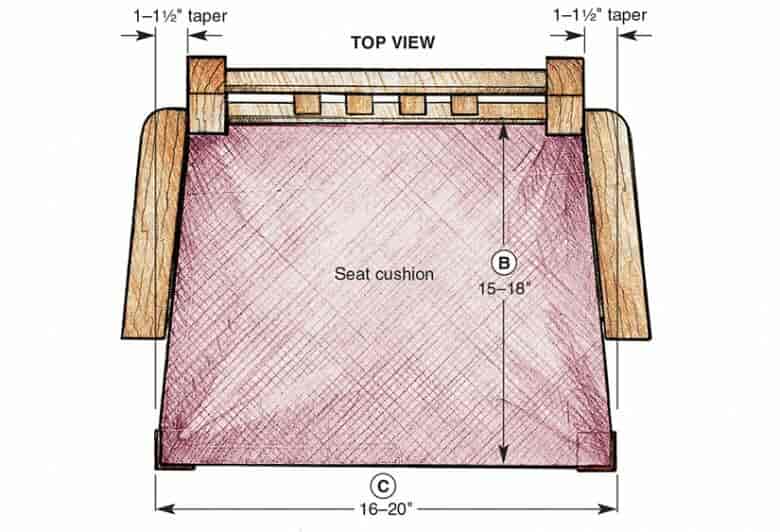
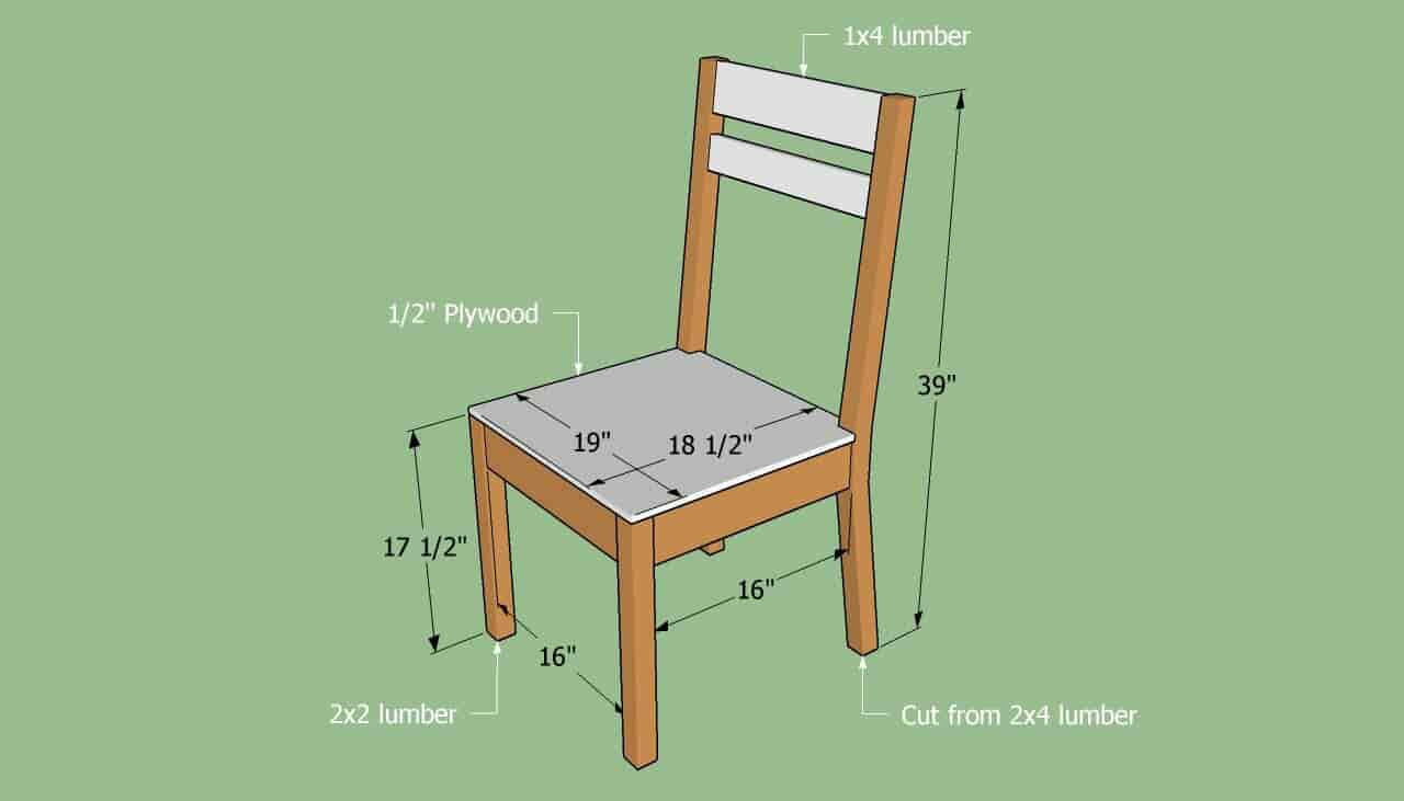
With some extended research, I found a good example with the measurements/angles too. I will not design that chair as its, I will make some modifications to its design. But, I will only take these dimensions as reference.
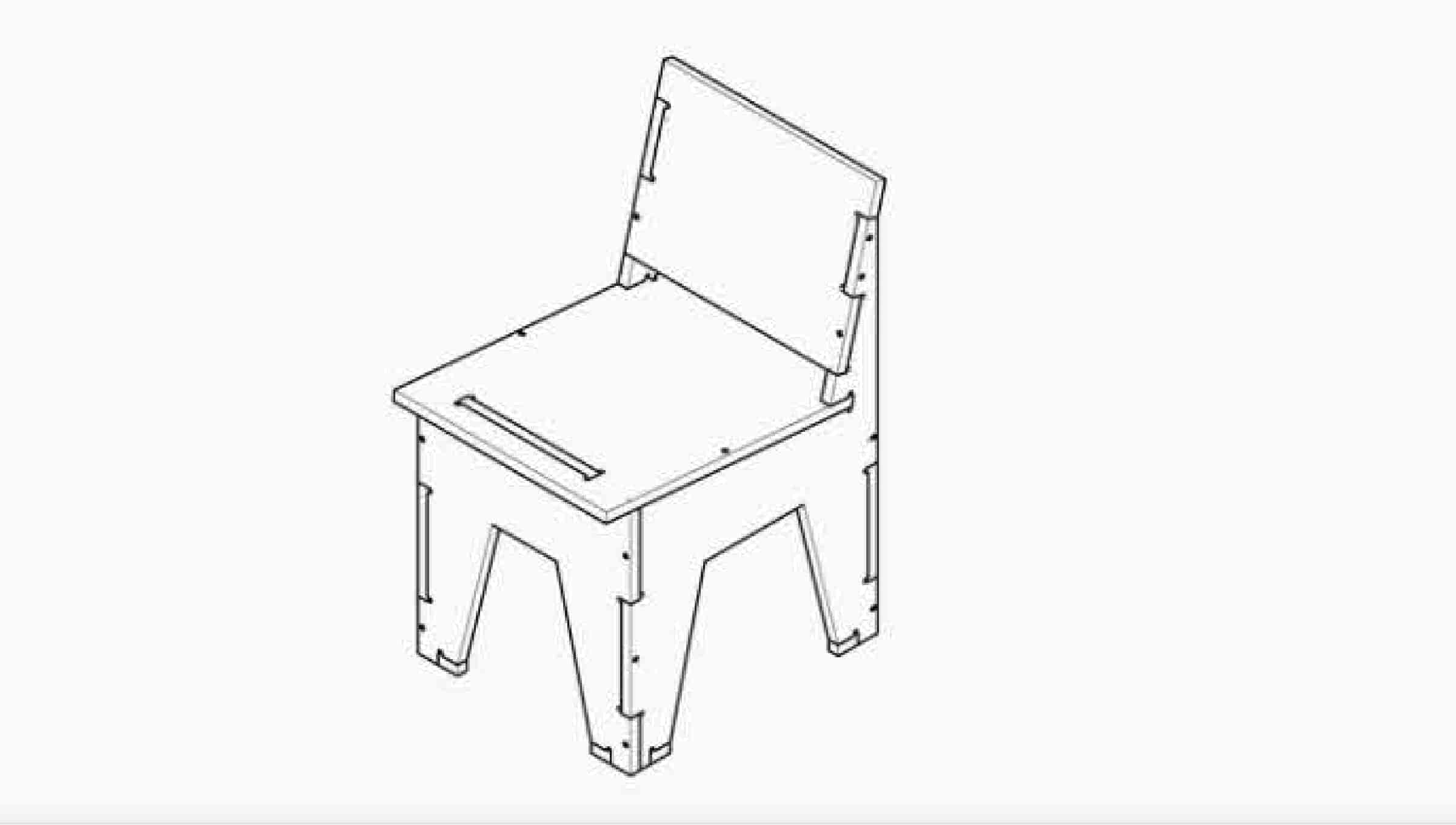
With more extended research I found that model. I guess it’s a beautiful model and it’s a CNC router friendly design. They are not providing any data or dimensions/angles about this model. But, I will figure it out according to the dimensions that we stated before.
Designing The Dopest Chair Ever
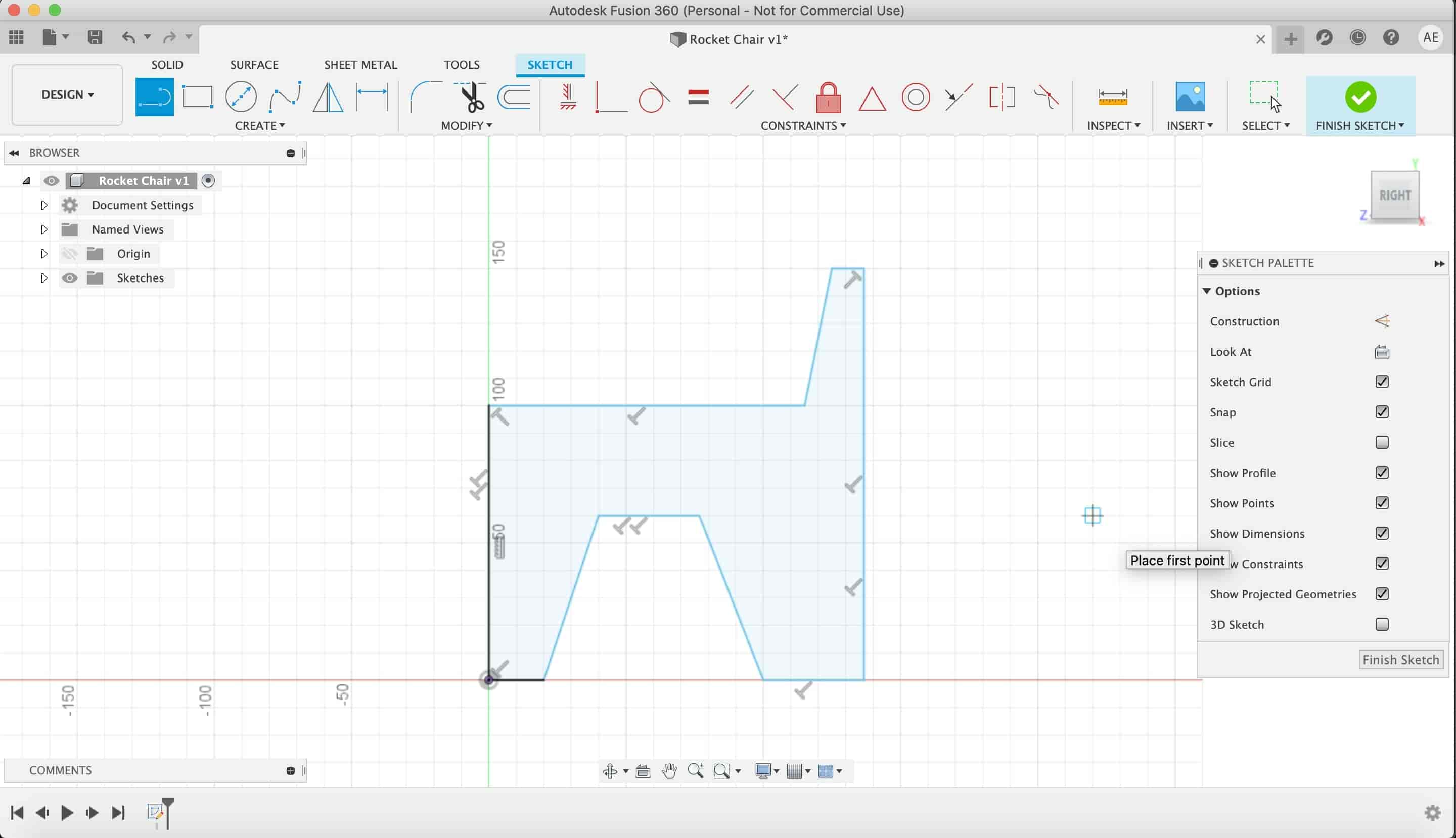
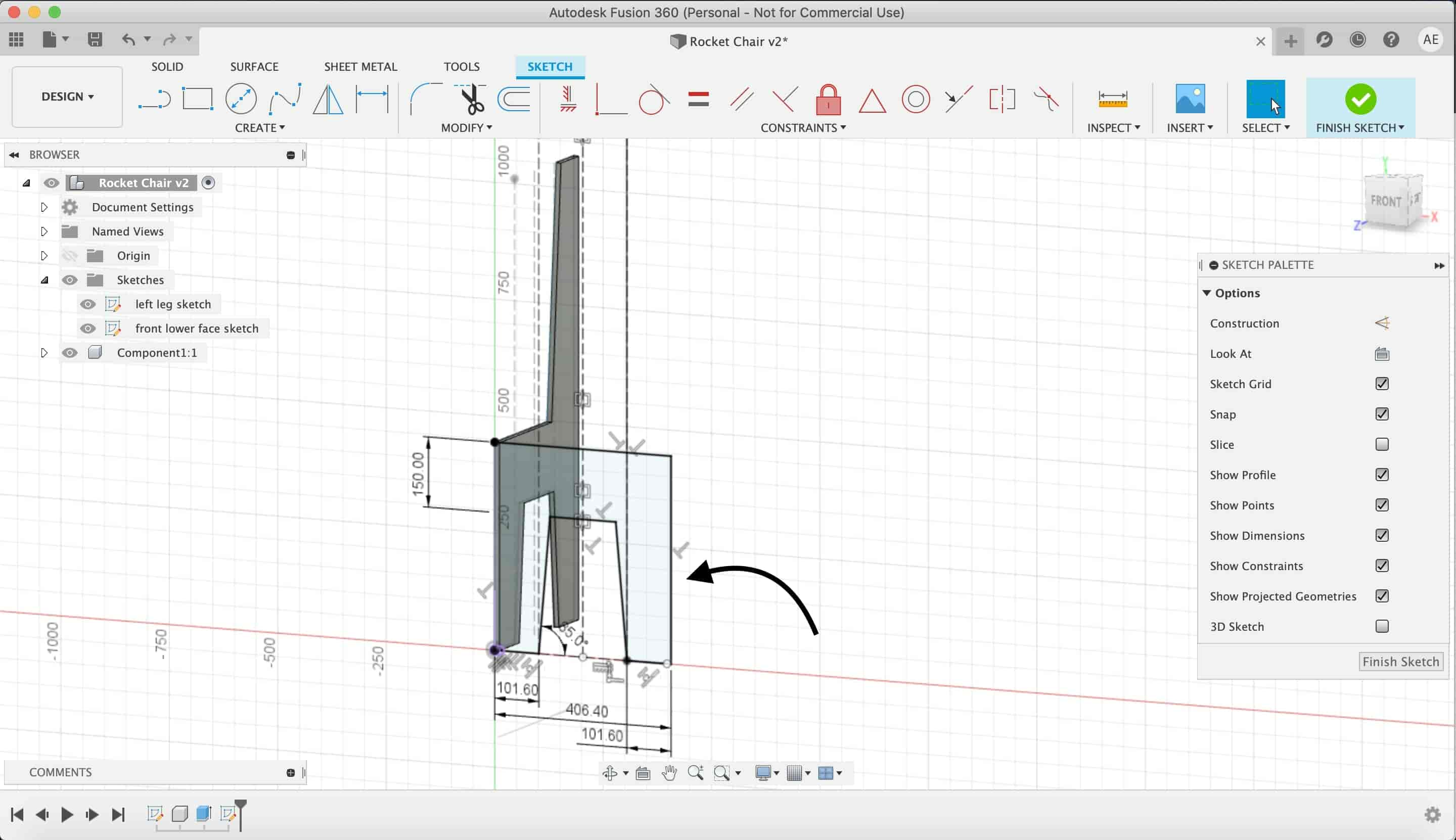
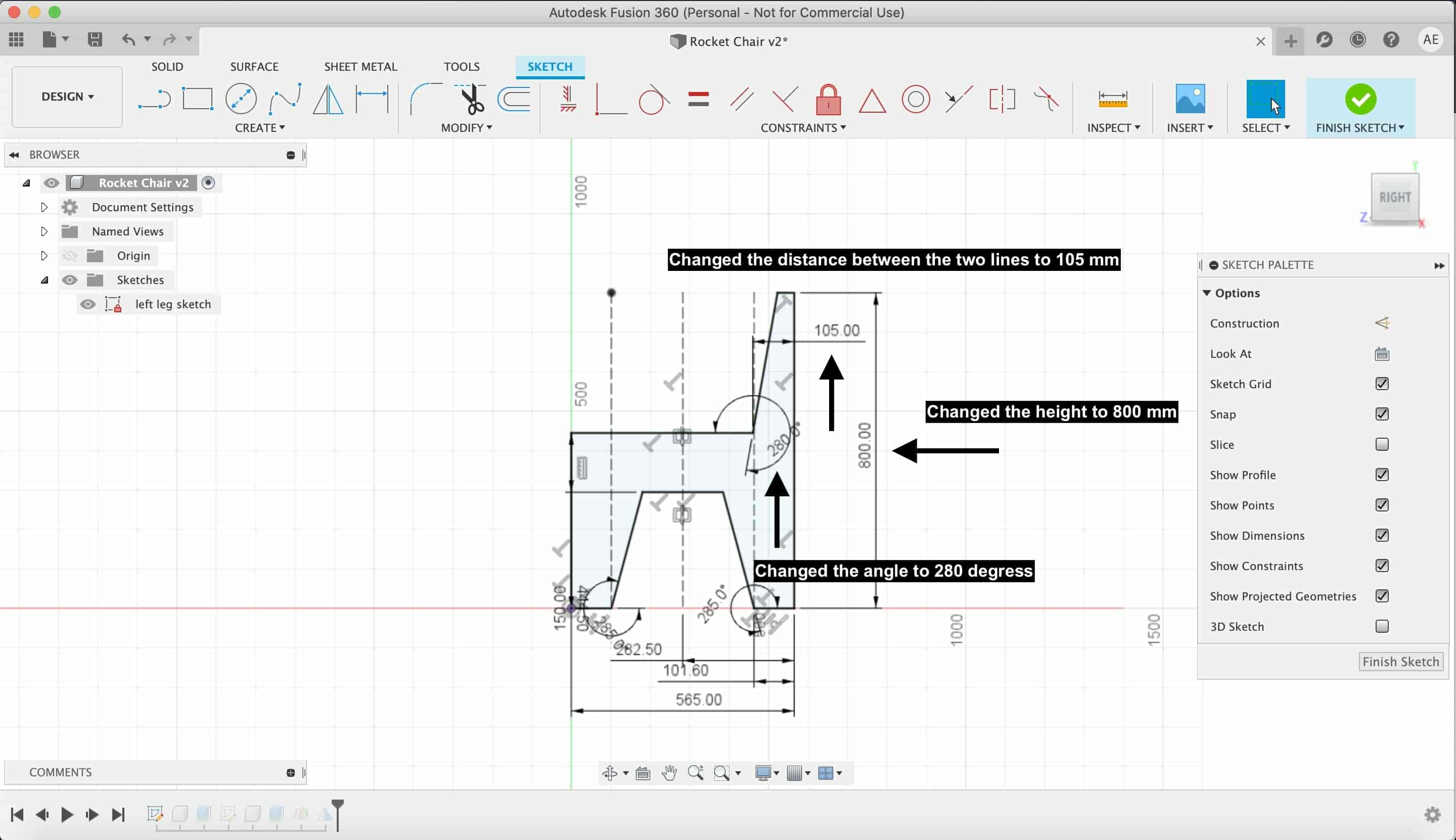
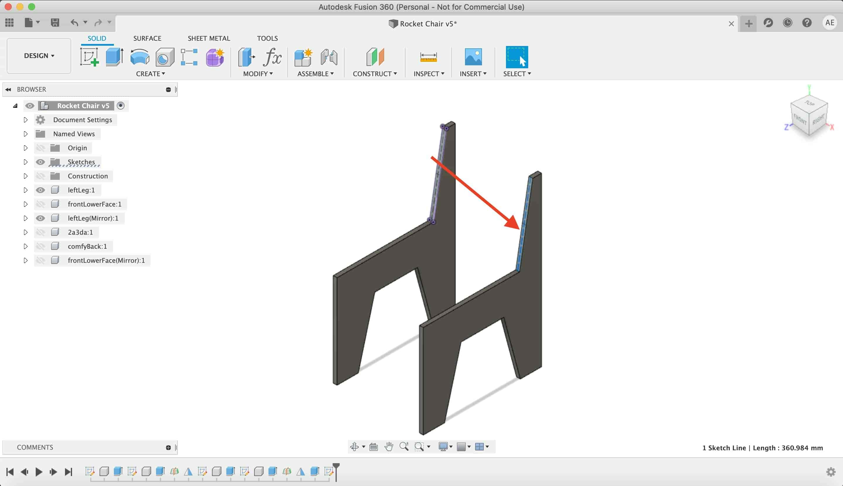
Now we have the references we need to design our own dope chair! Let’s do it. I’m using Fusion360 for this job. First things first, I plan to draw the left leg first. I drew a hard sketch without any dimensions. Then, I assigned some dimensions to it according to the reference that we stated before. I feel that the dimensions are not very suitable for each other. Bit, we will fix that later.
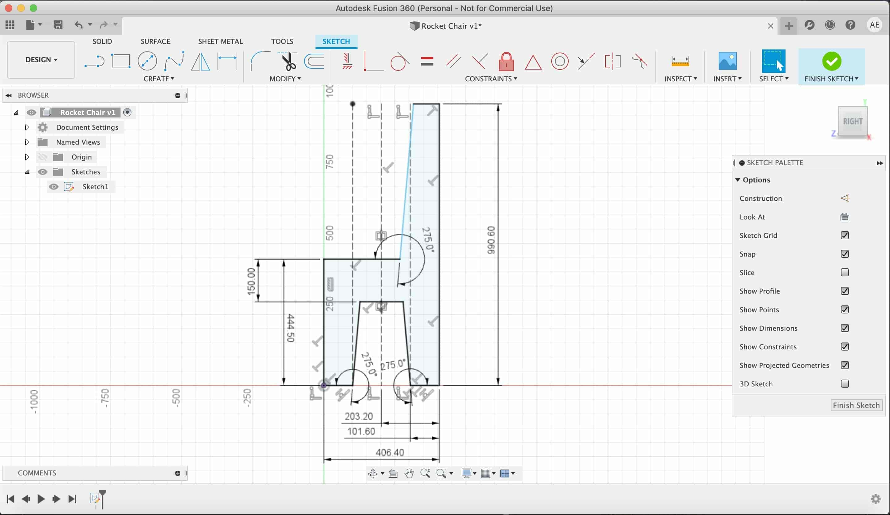
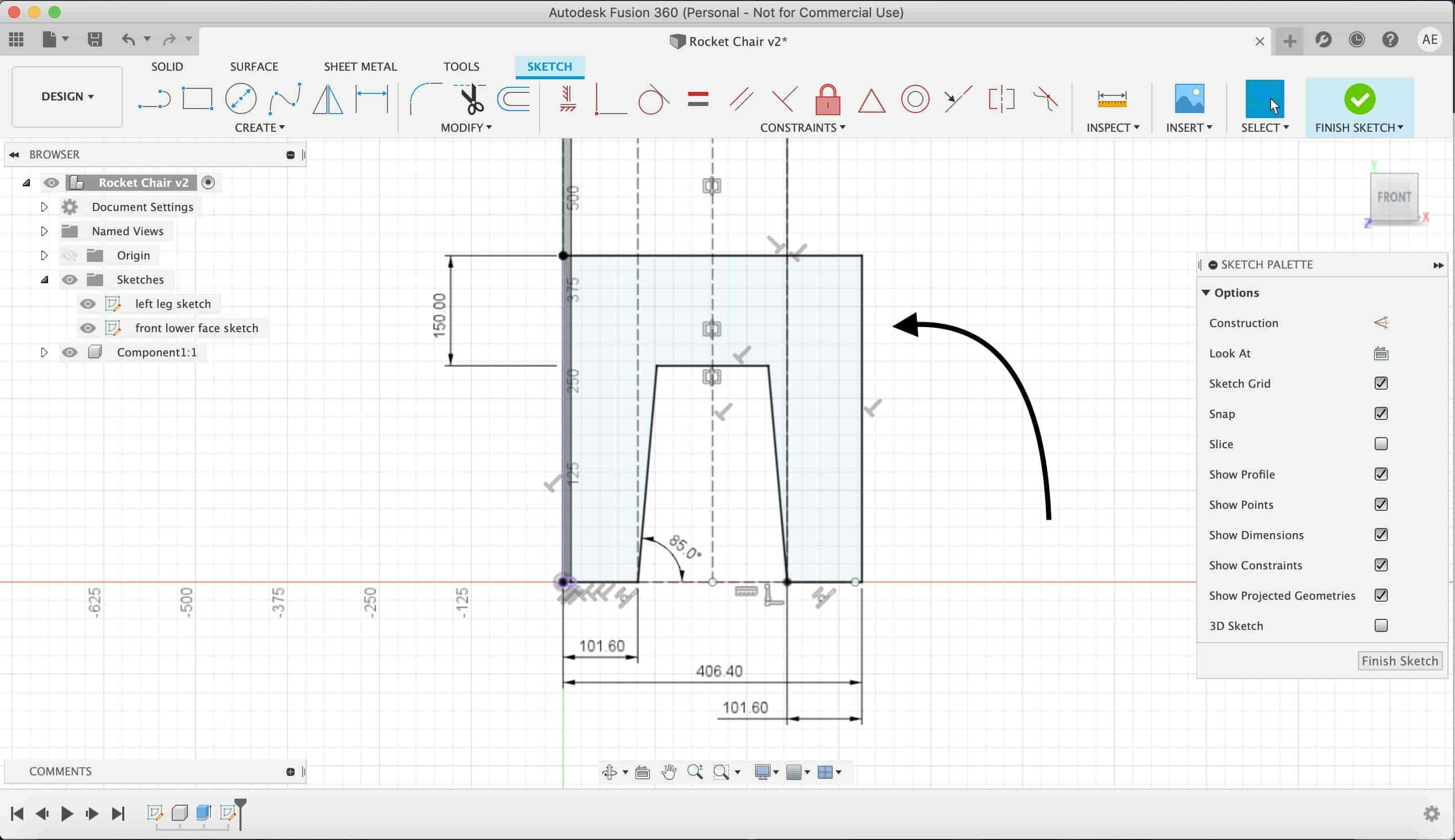
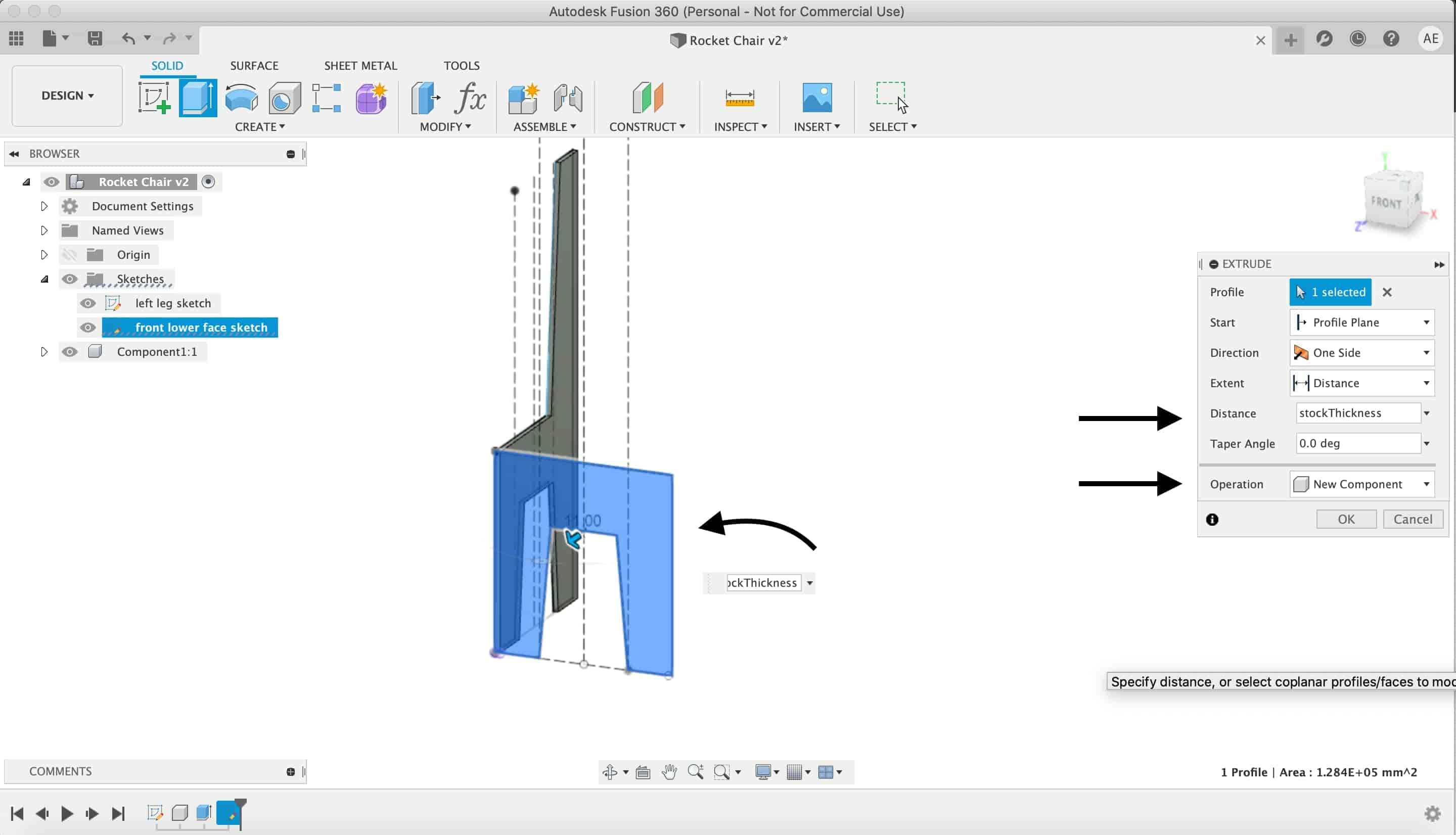
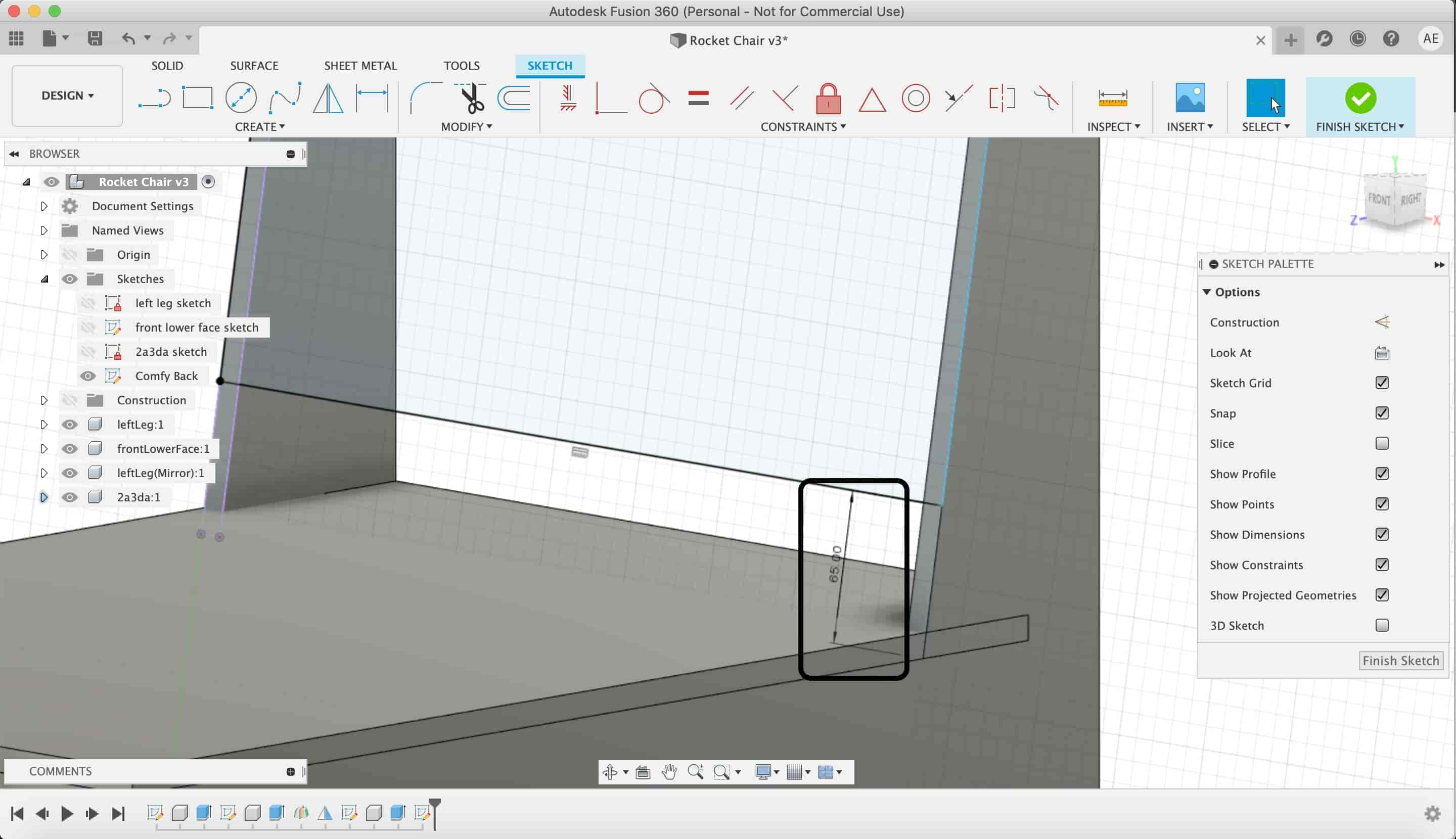
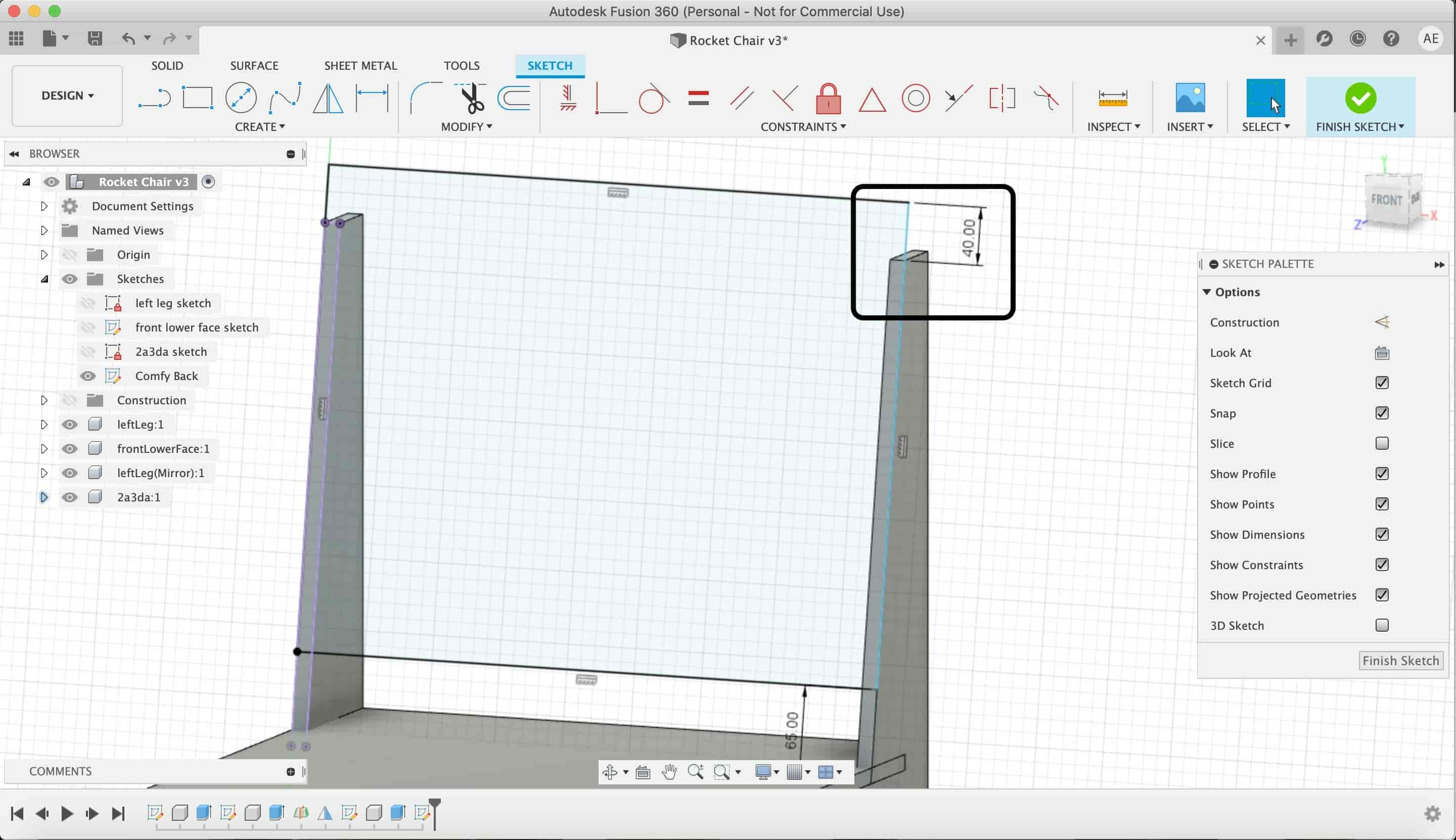
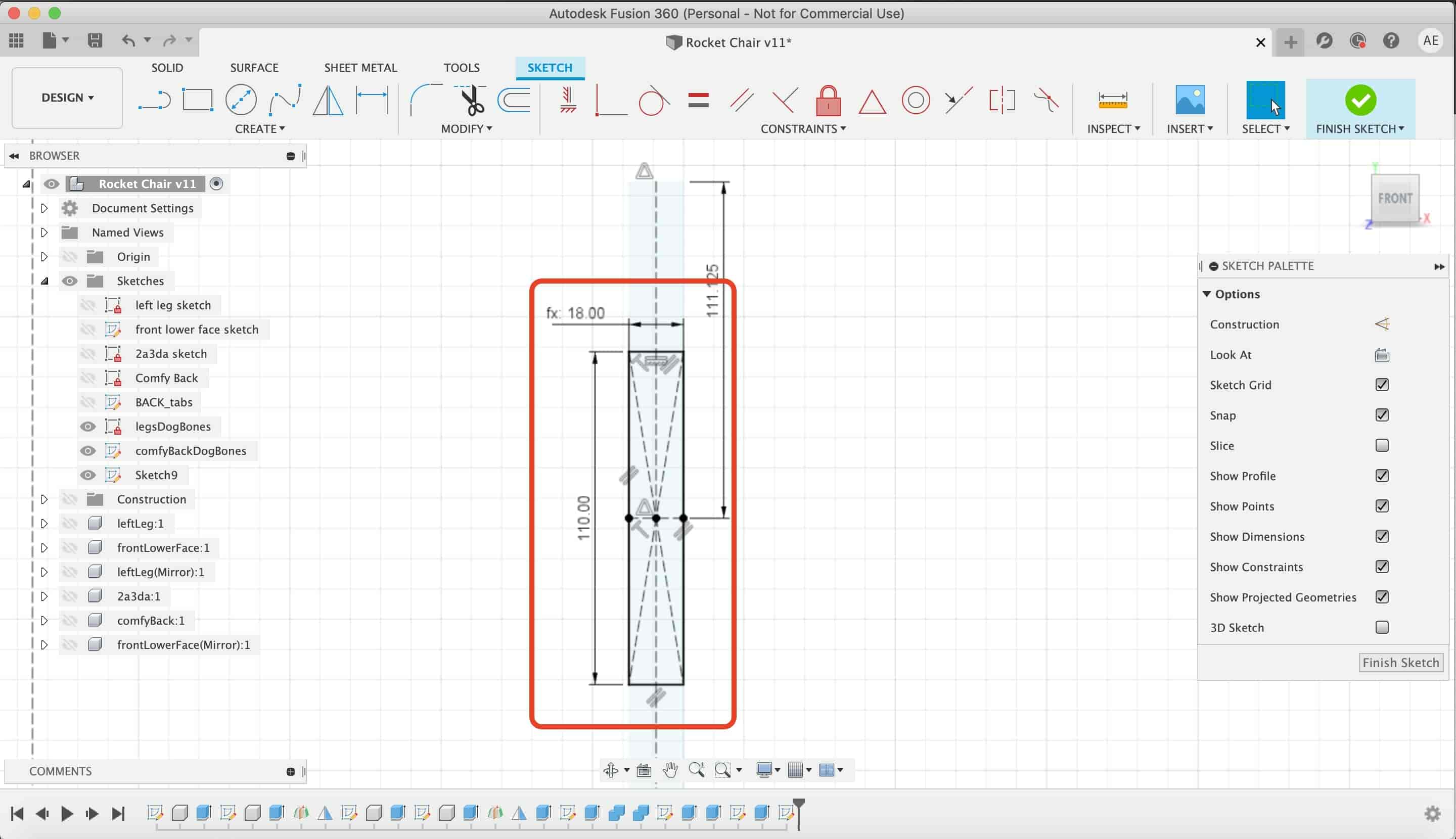
Next, let’s draw the front lower leg. I drew a new sketch on the front face of the left chair leg. And draw 40.6cm front lower leg.
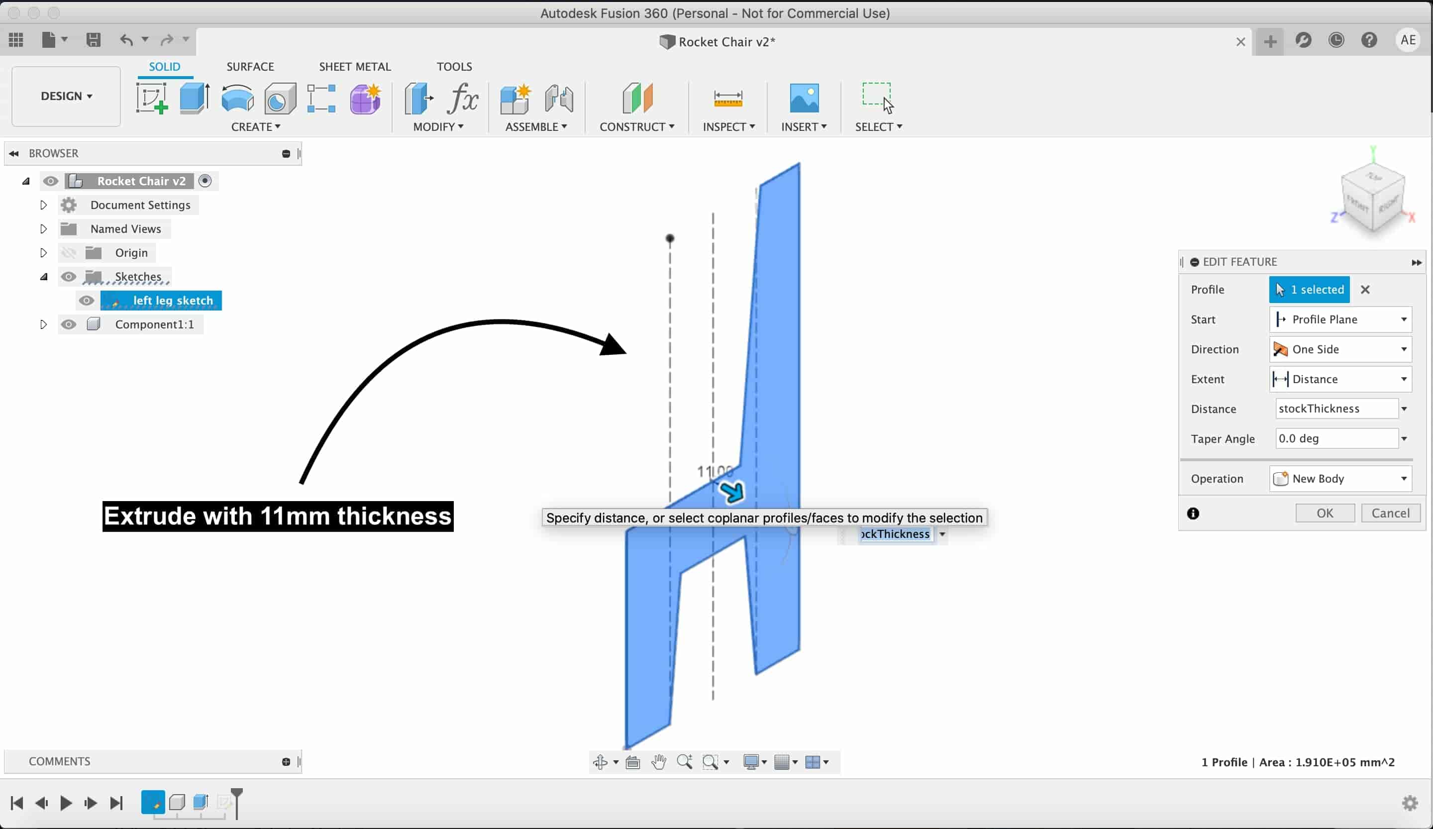
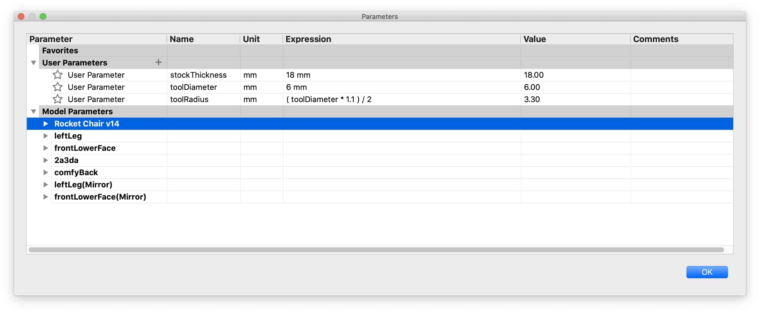
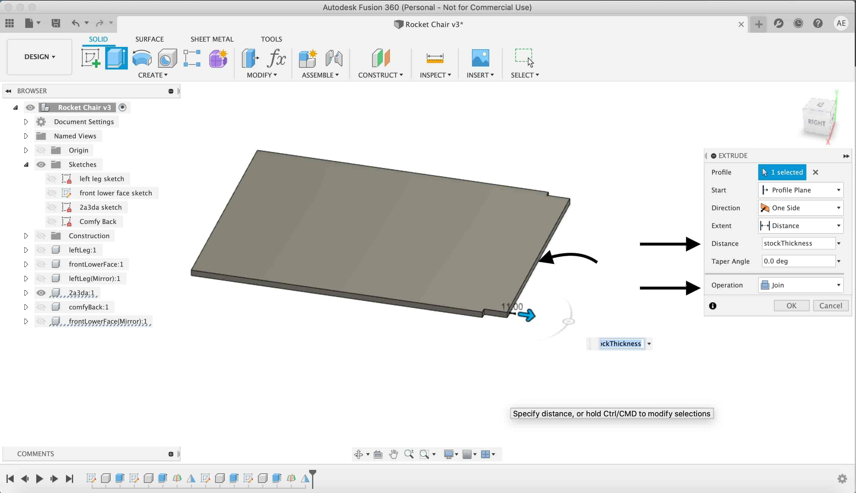
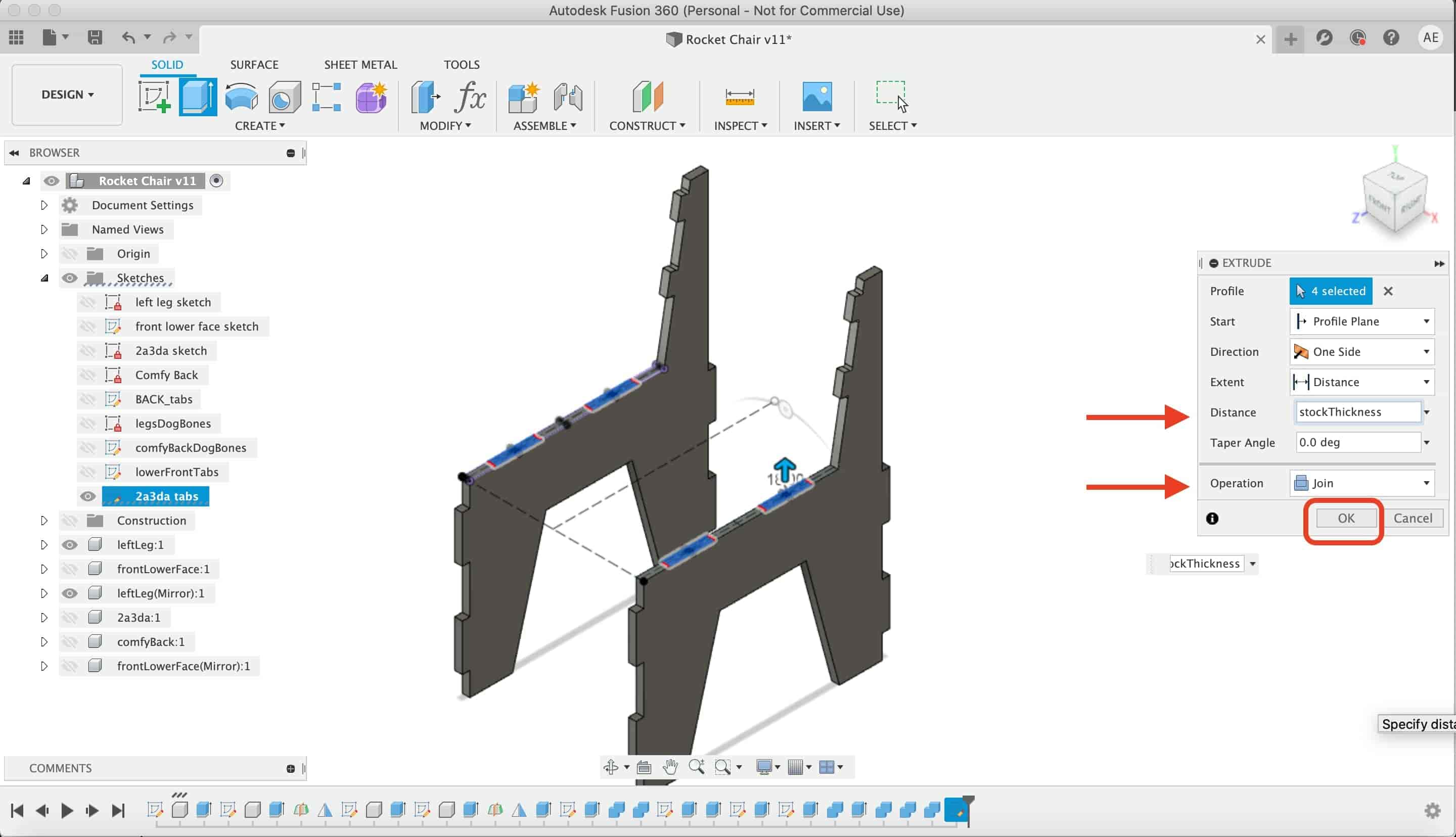
Then extrude that leg with the “stock thickness” variable. We are working parametric to make it easy in case we wanted to change later the cutting tool diameter or the wood stock thickness.
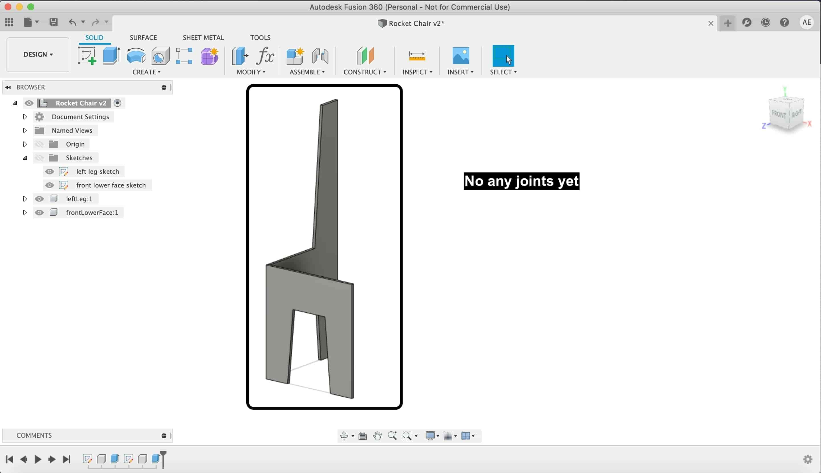
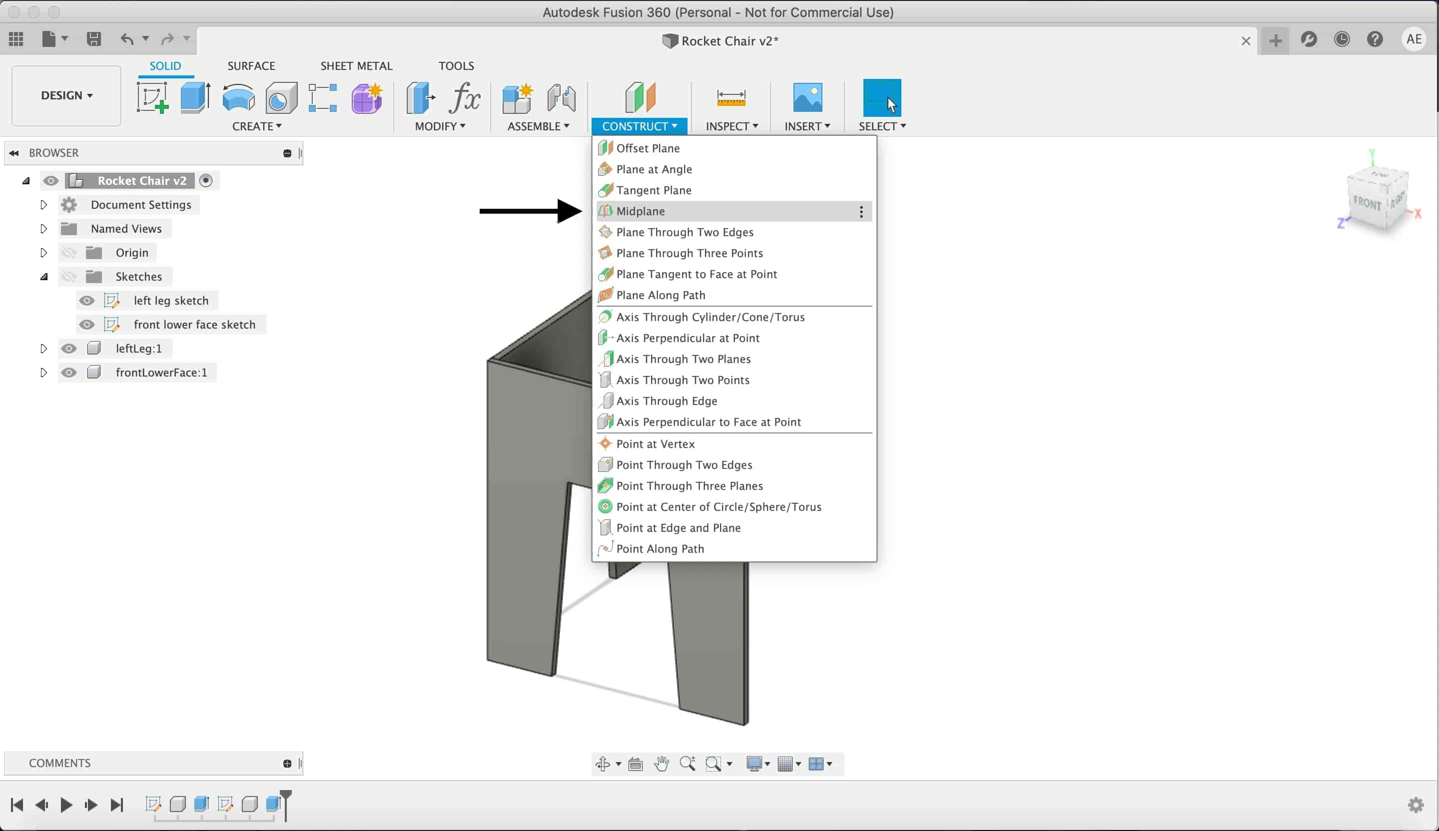
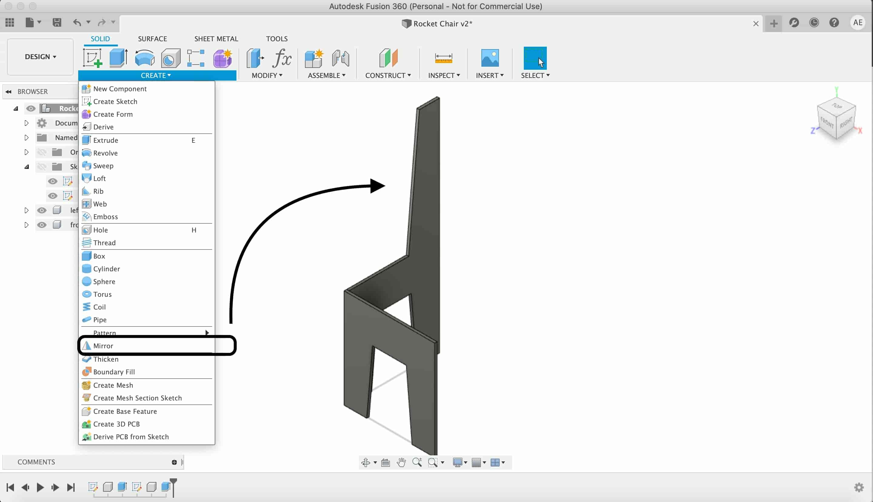
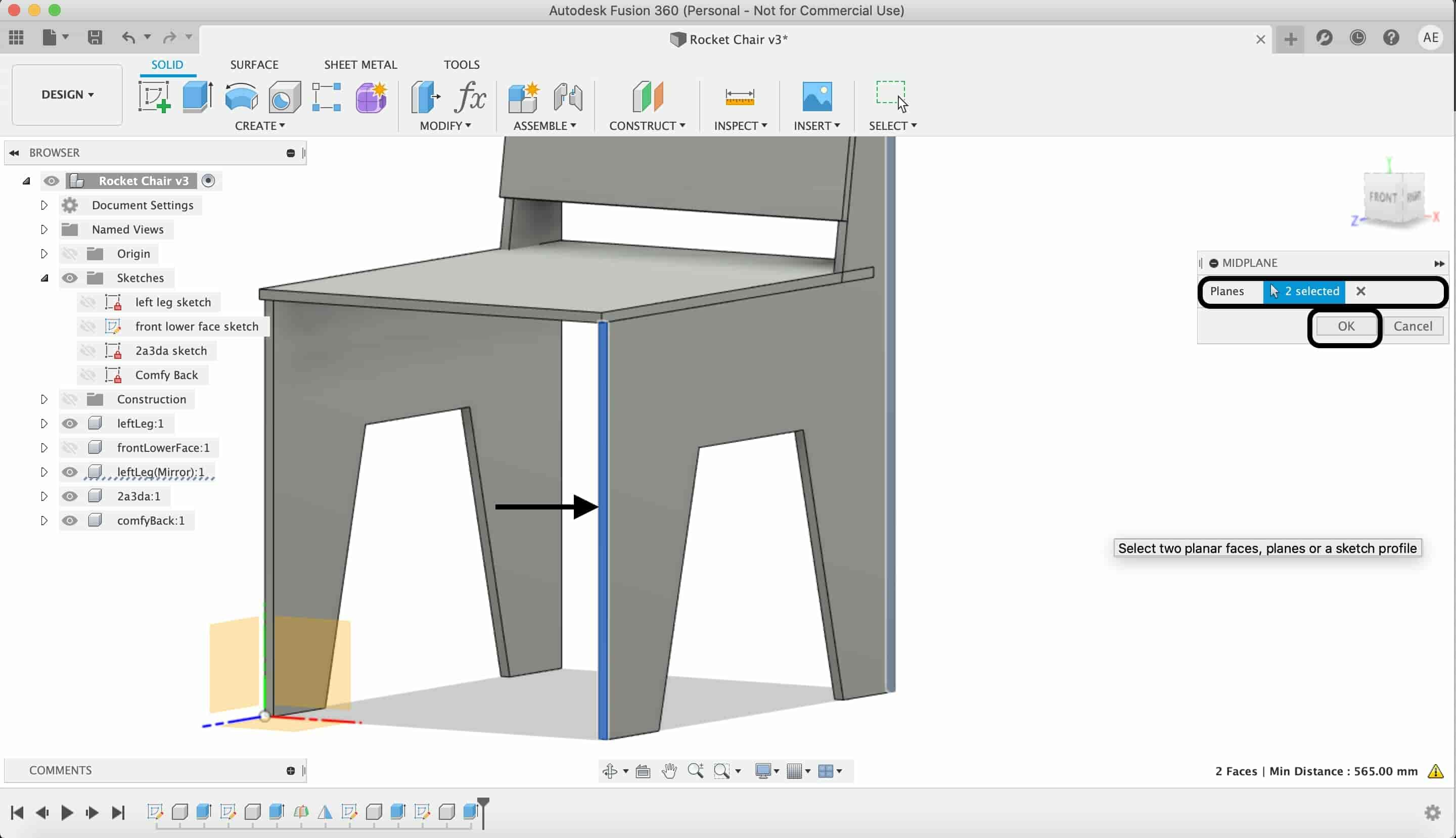
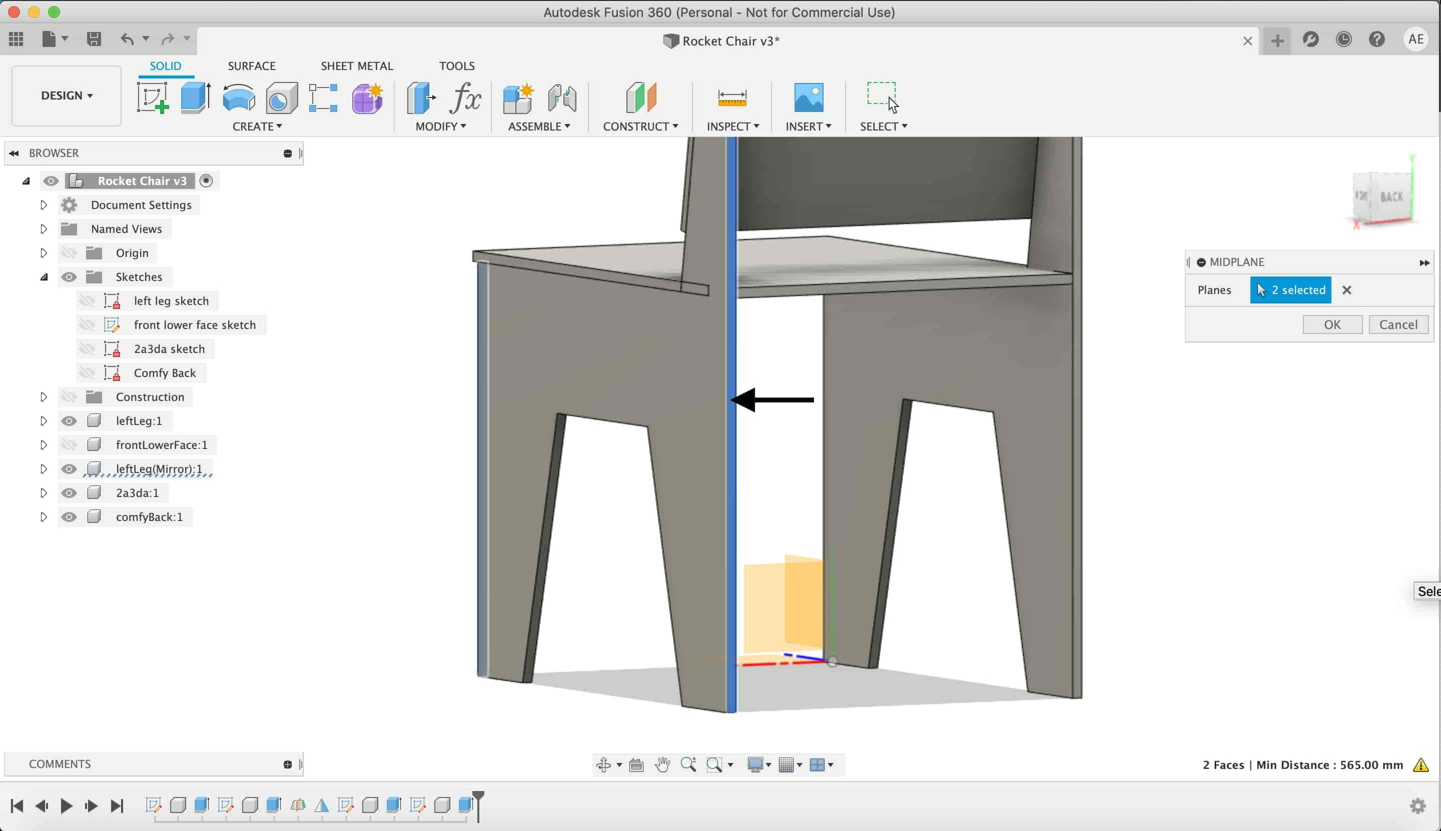
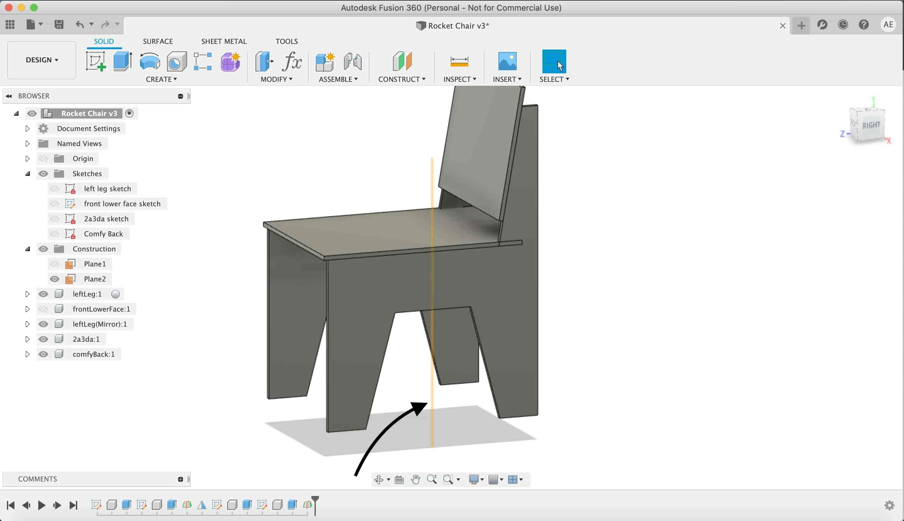
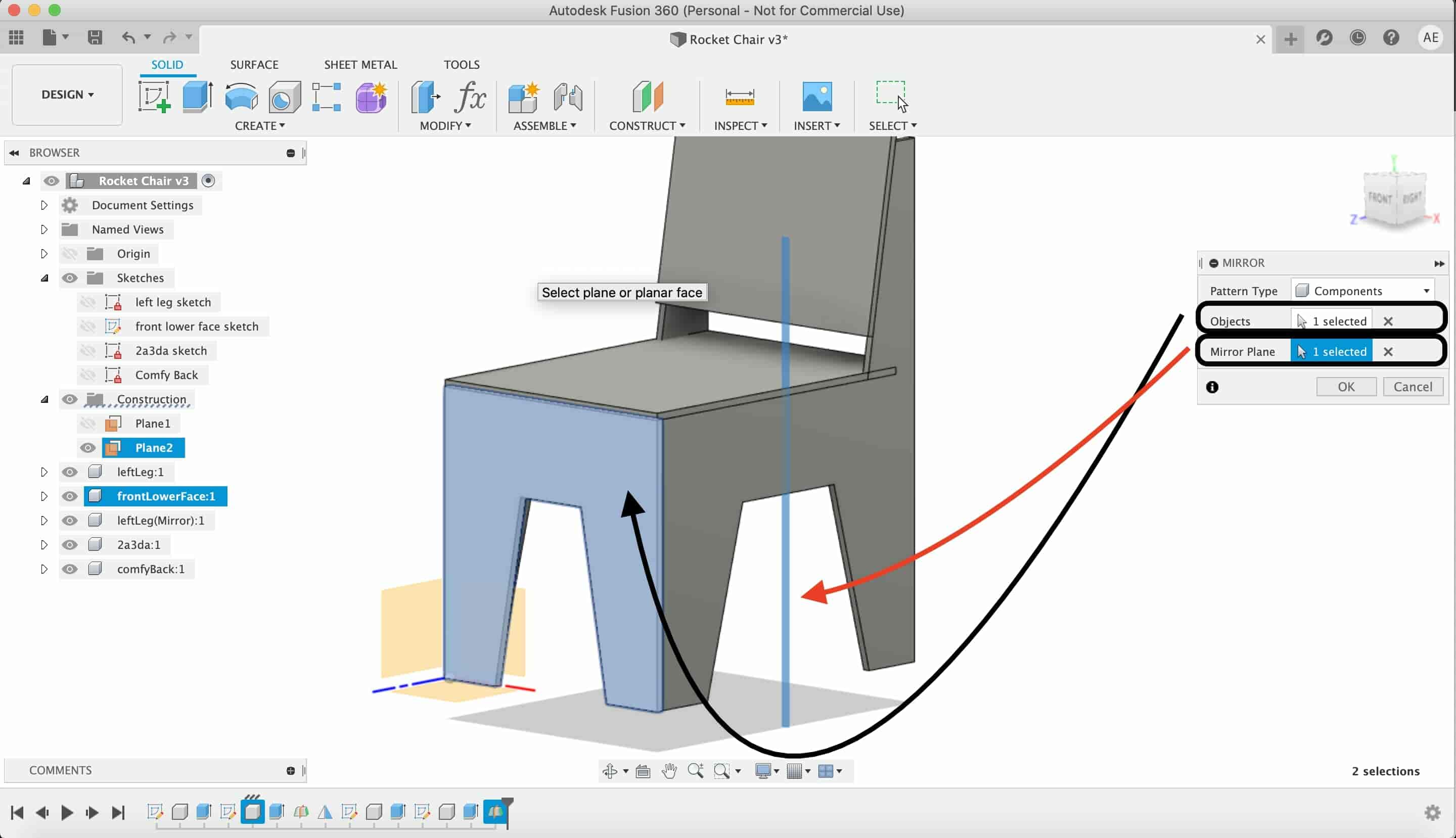
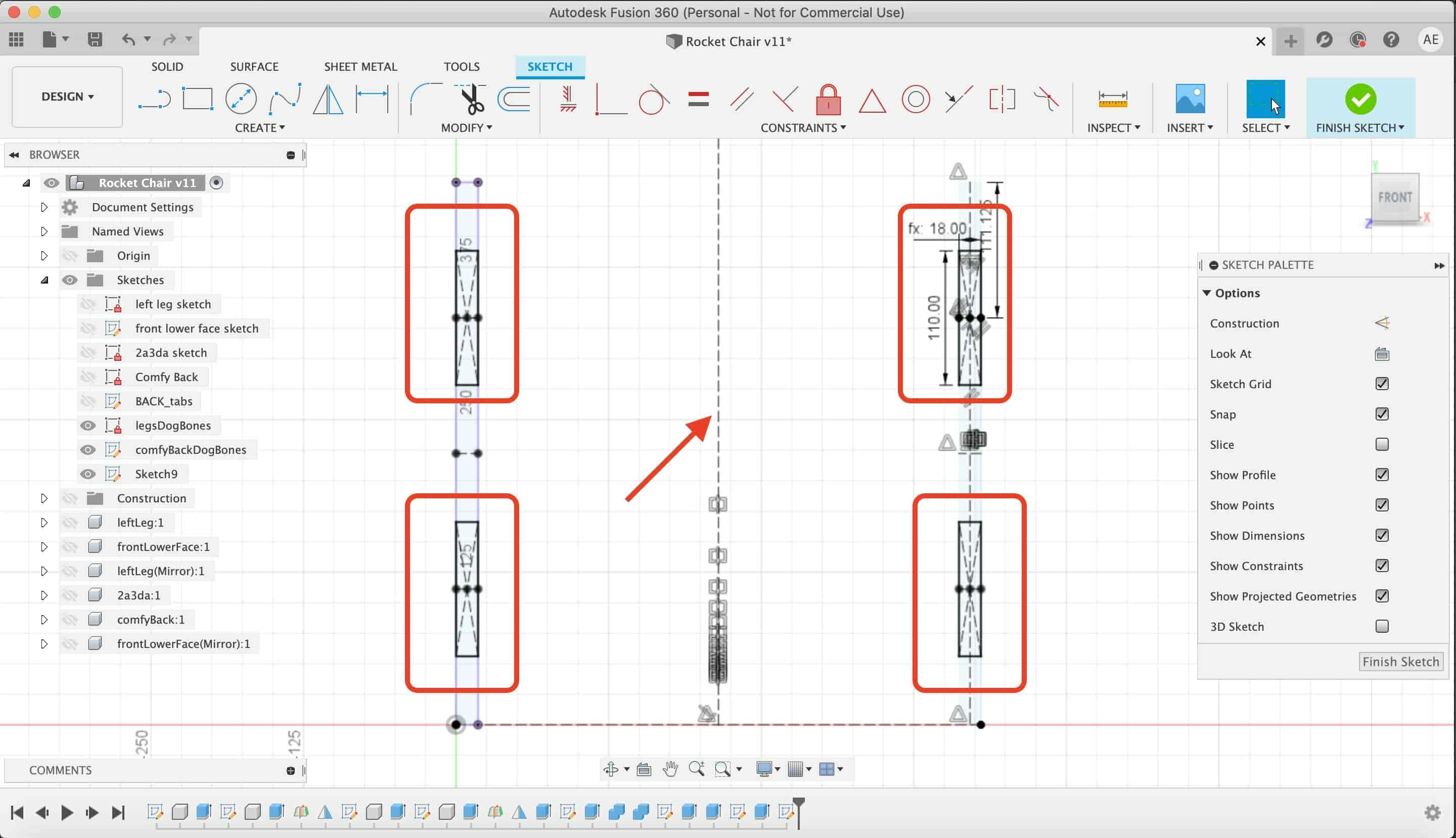
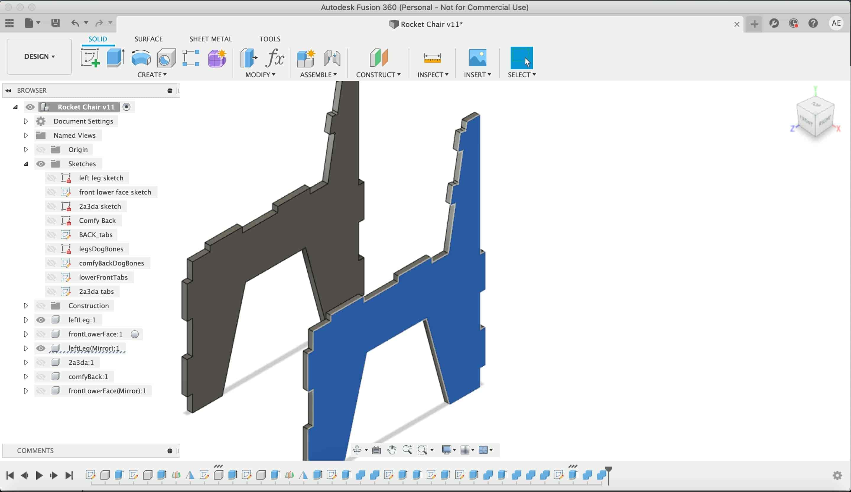
To make the right chair leg, we will not draw a whole new sketch with the exact dimensions. We will mirror the left leg. To do that, we need a midplane between the two faces of the front lower leg.
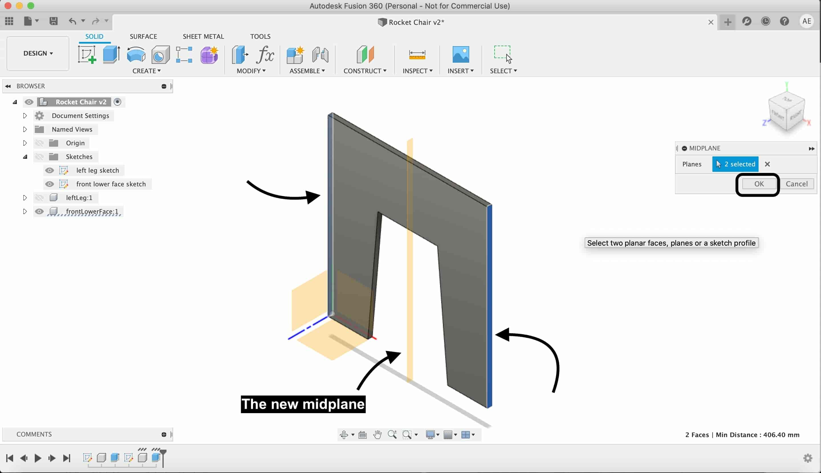
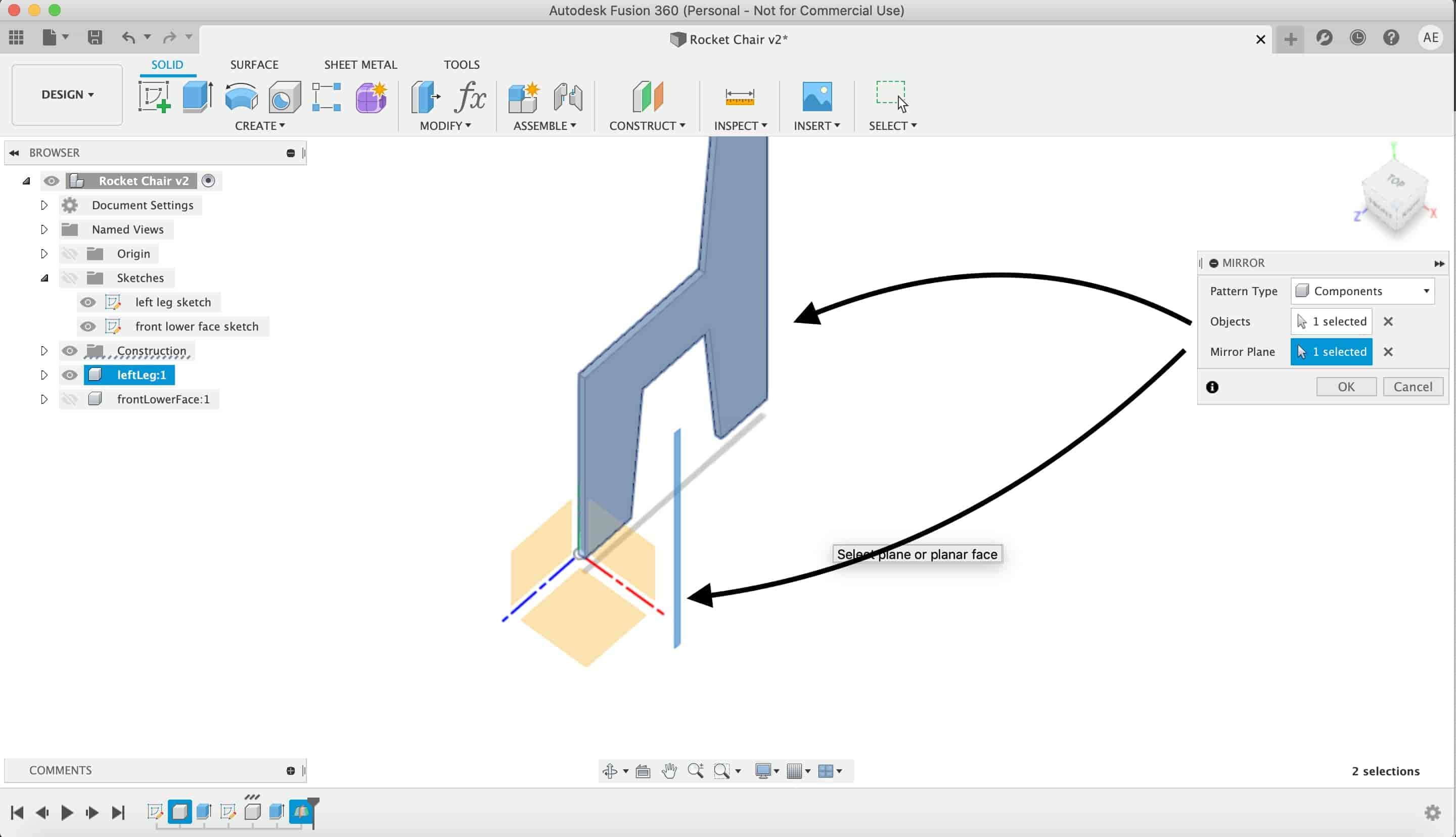
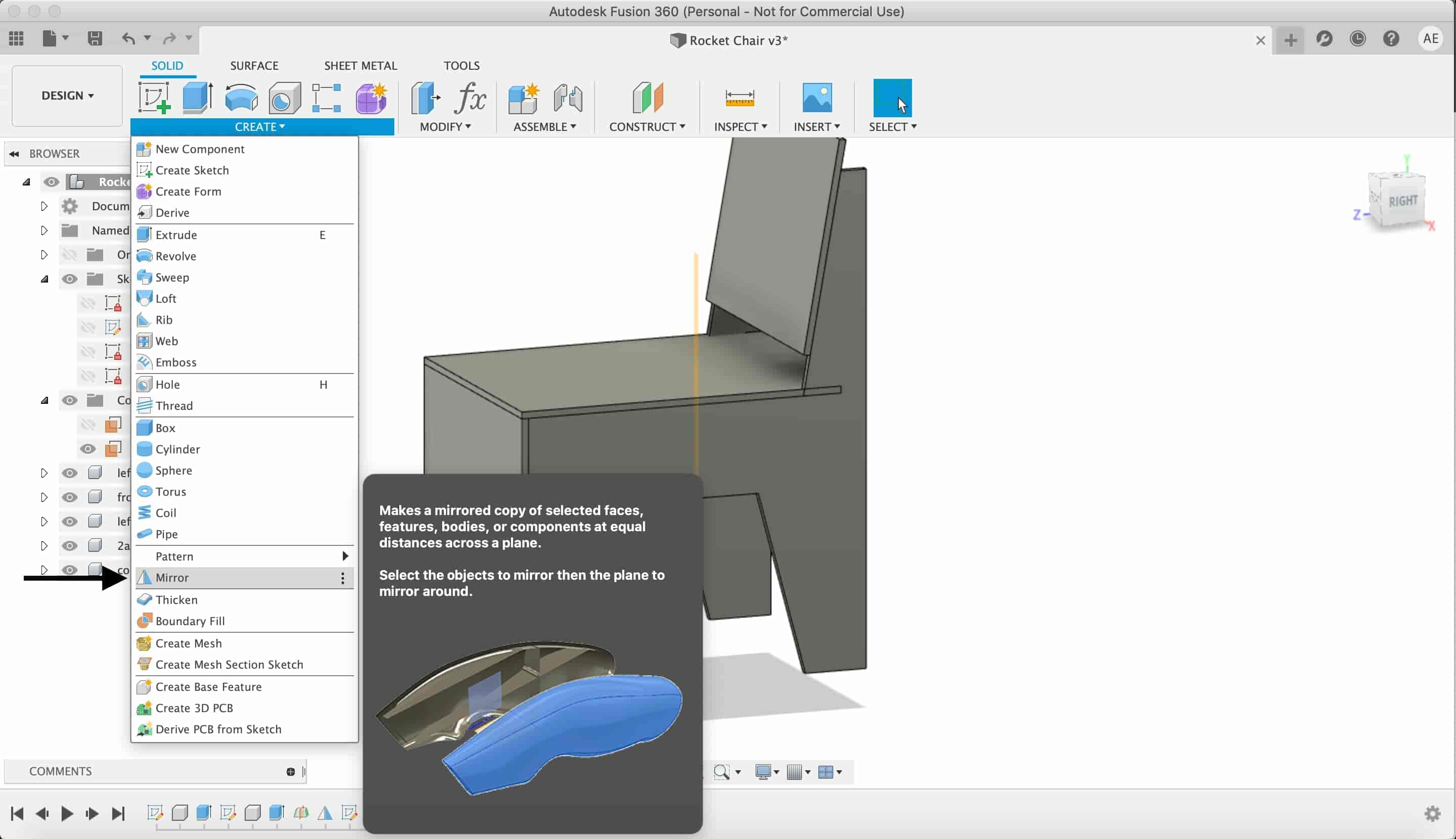
Then use the mirror tool to make a second mirrored copu of the left chair leg.
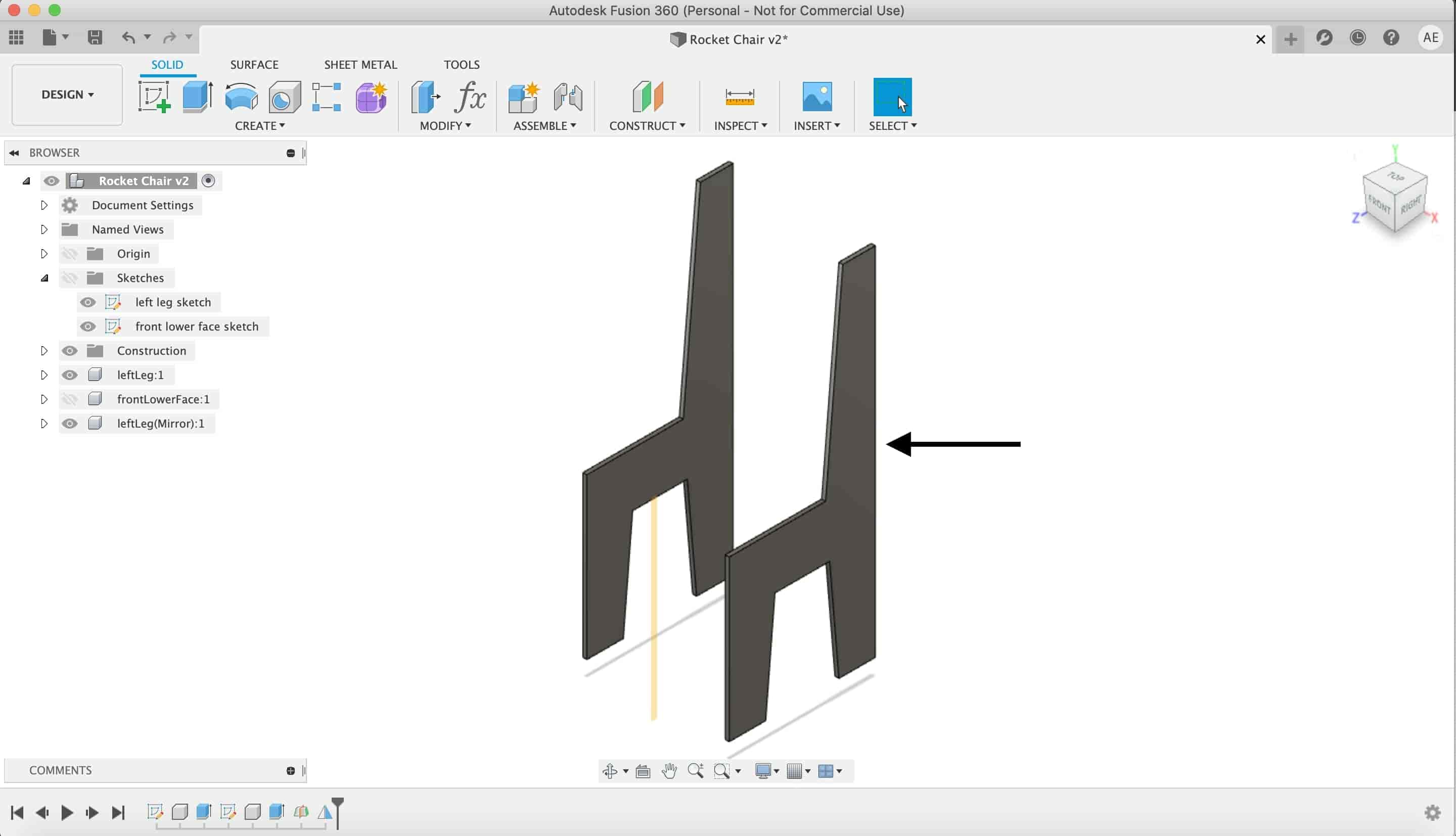
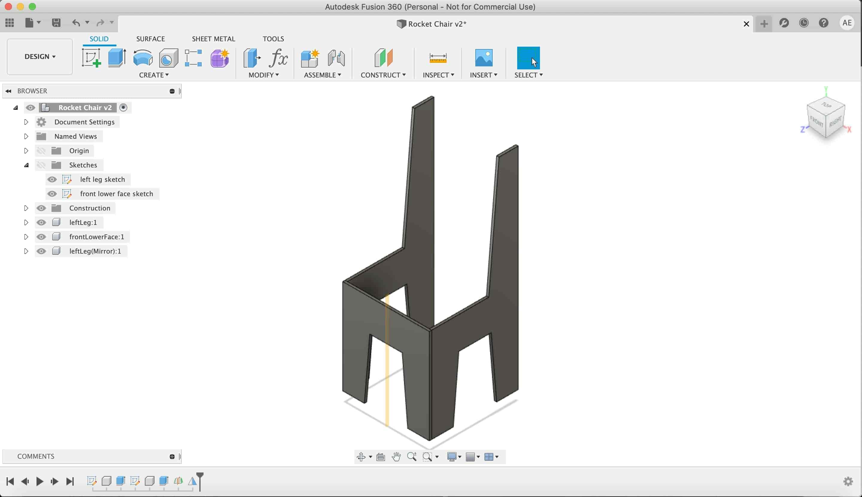
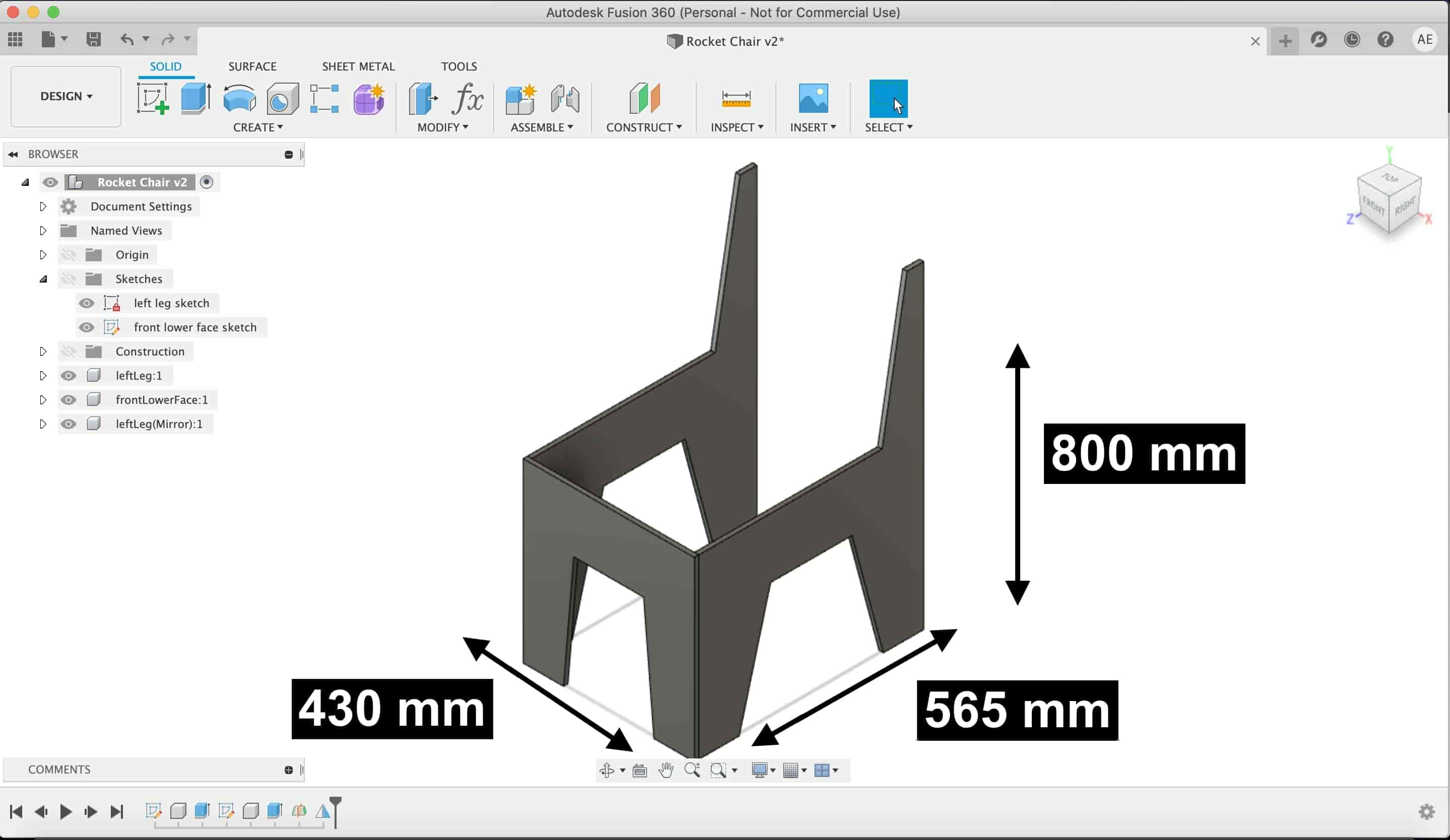
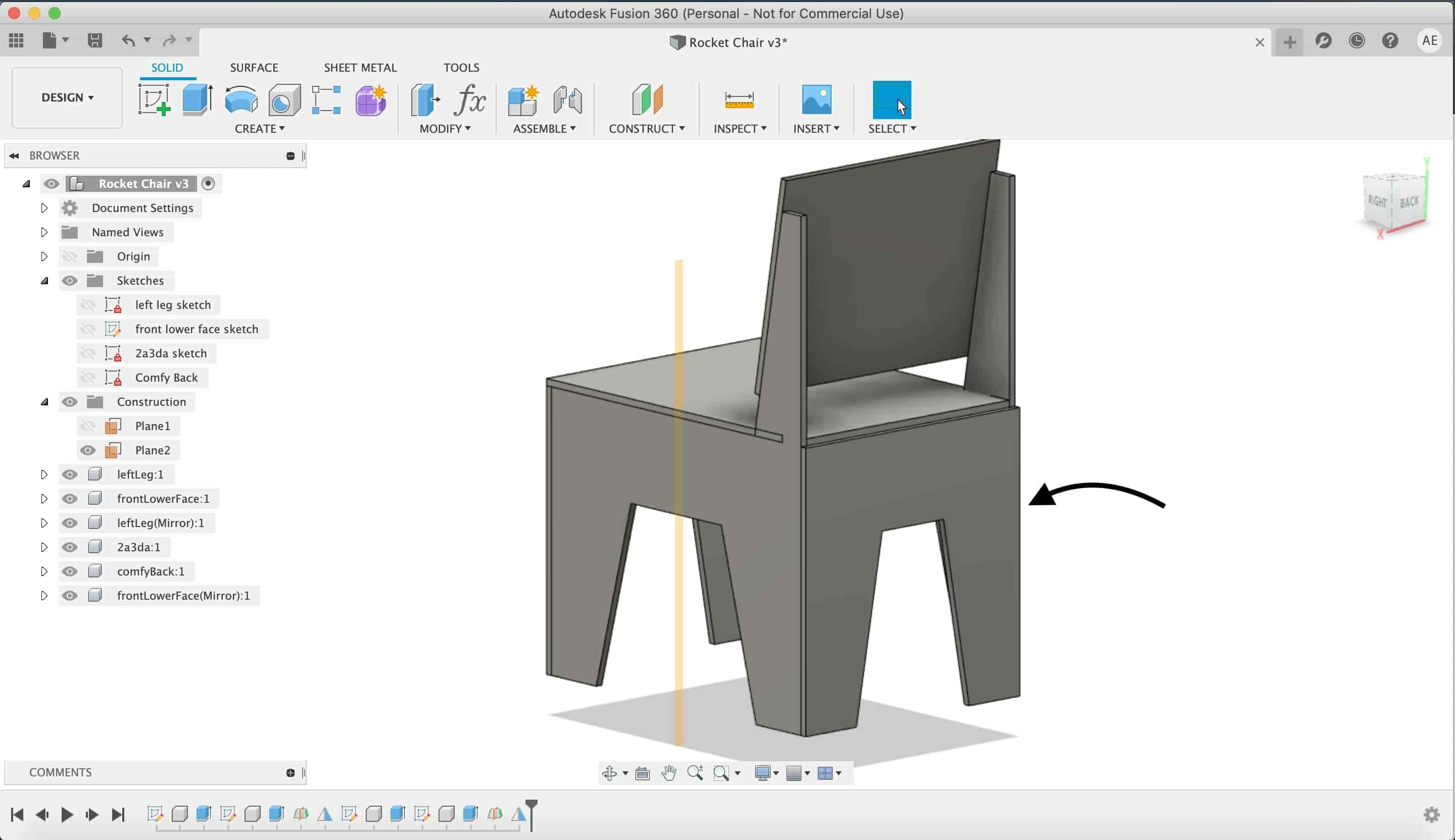
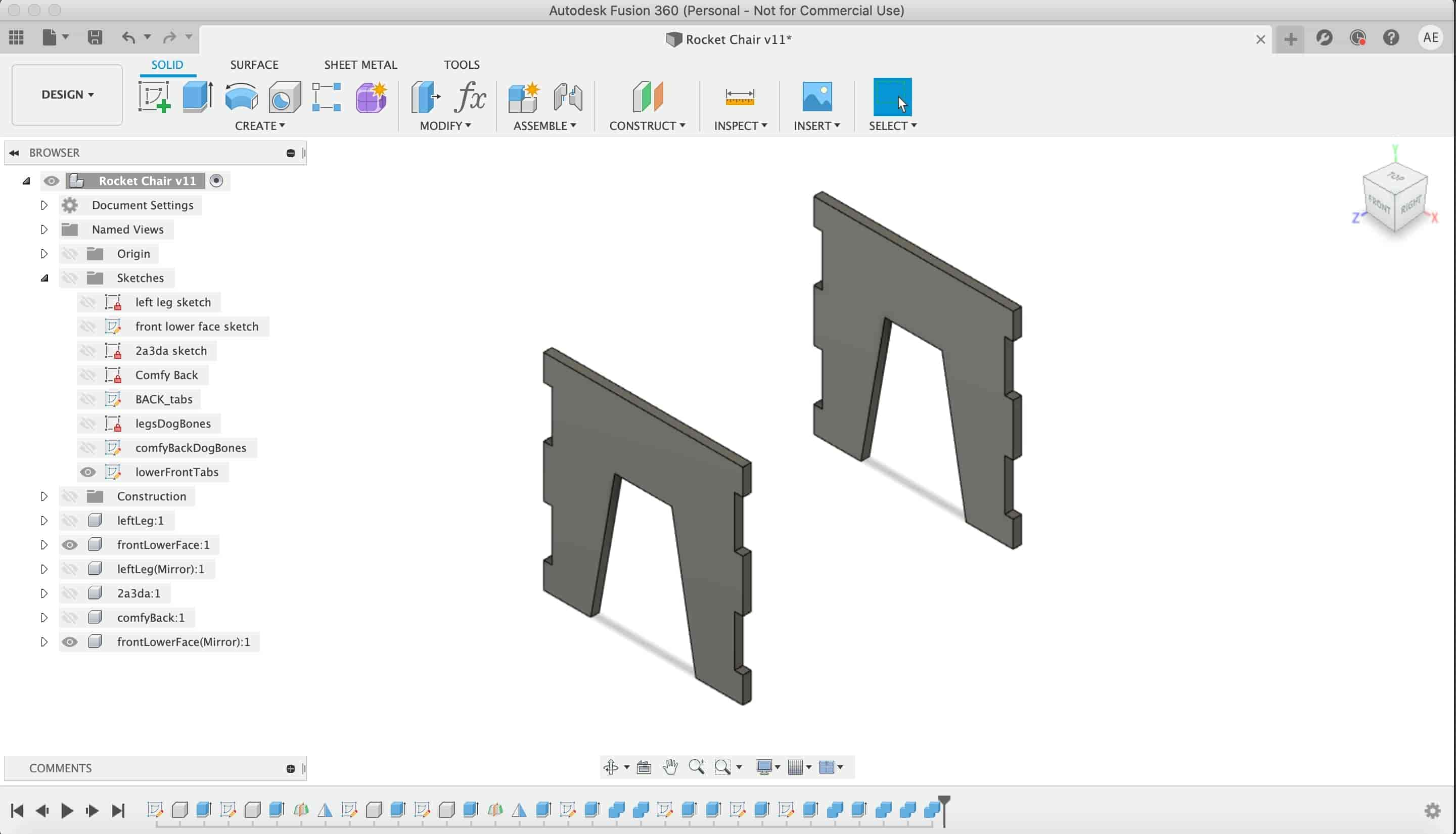
Here we go, we now have two chair legs and one lower front face leg.
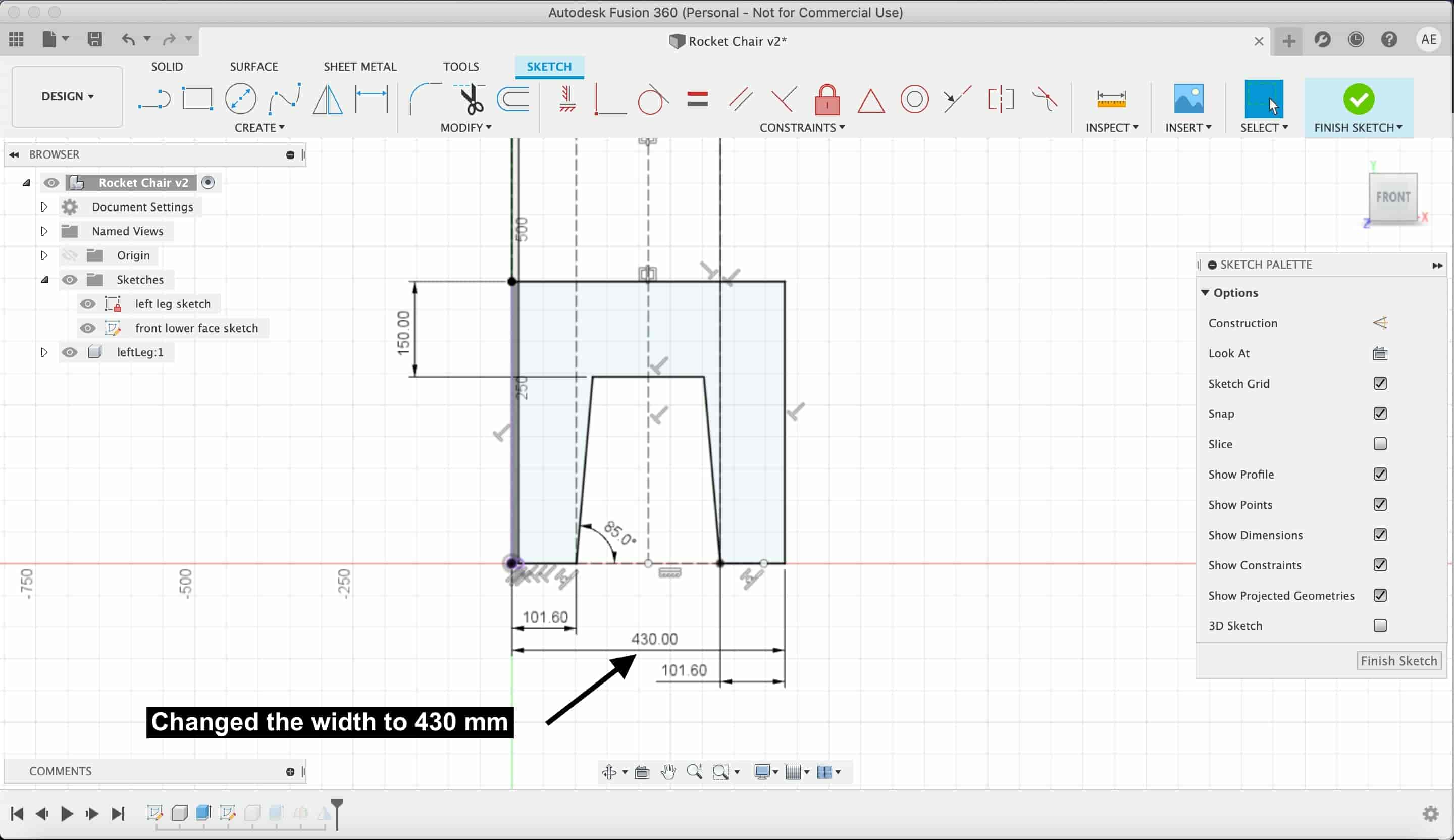
Actually, I dont feel comfortable with that chair dimensions, I wanna make the cair more wider and not that tall. I change the front lower face width to 43cm. Also, tweaked the left and right legs dimensions a lil bit to make it more presentable.
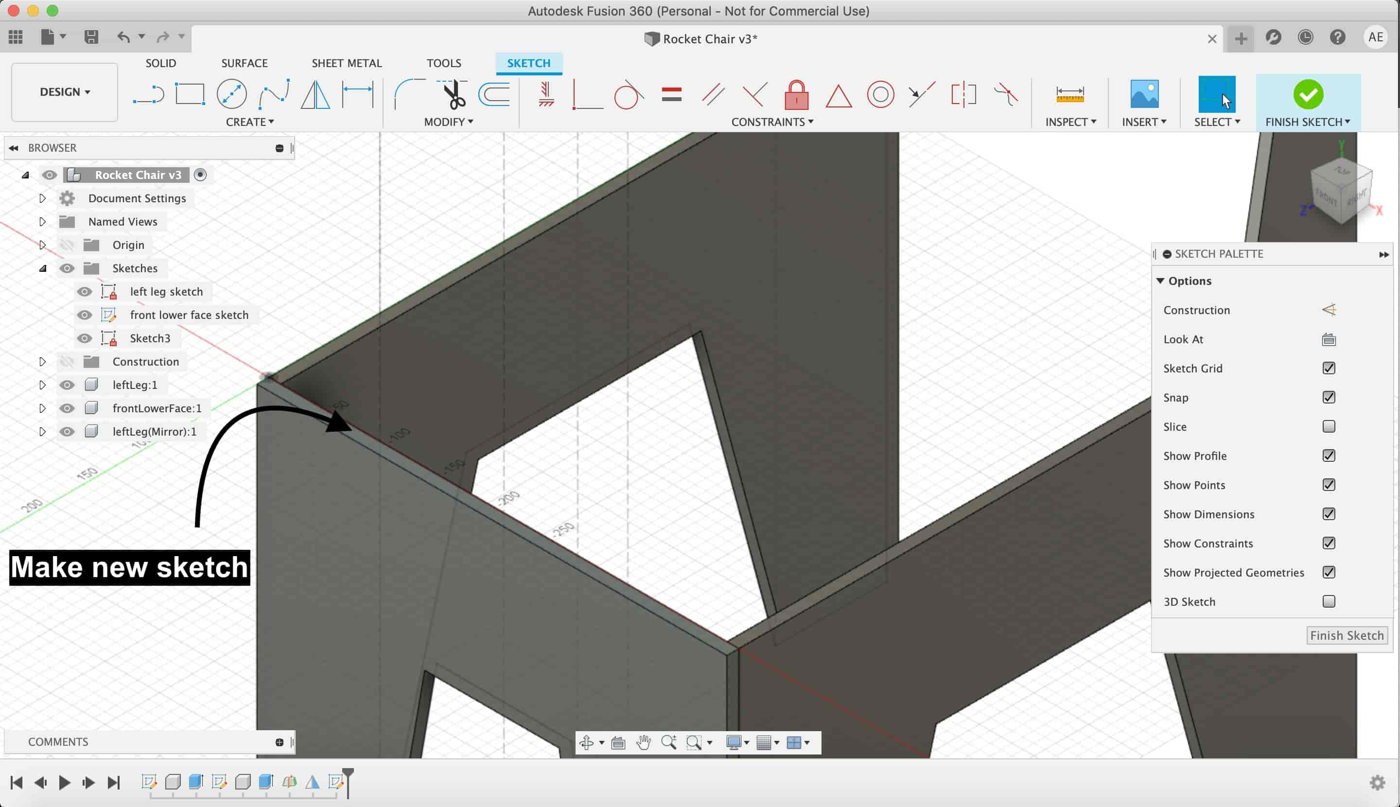
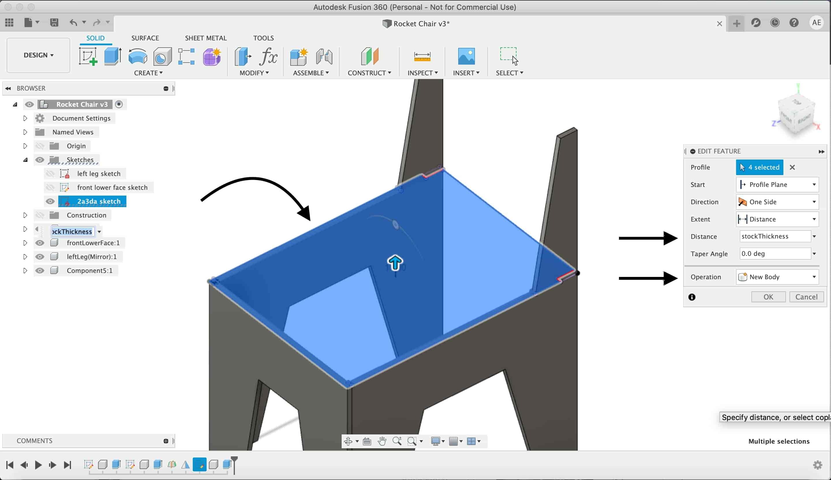
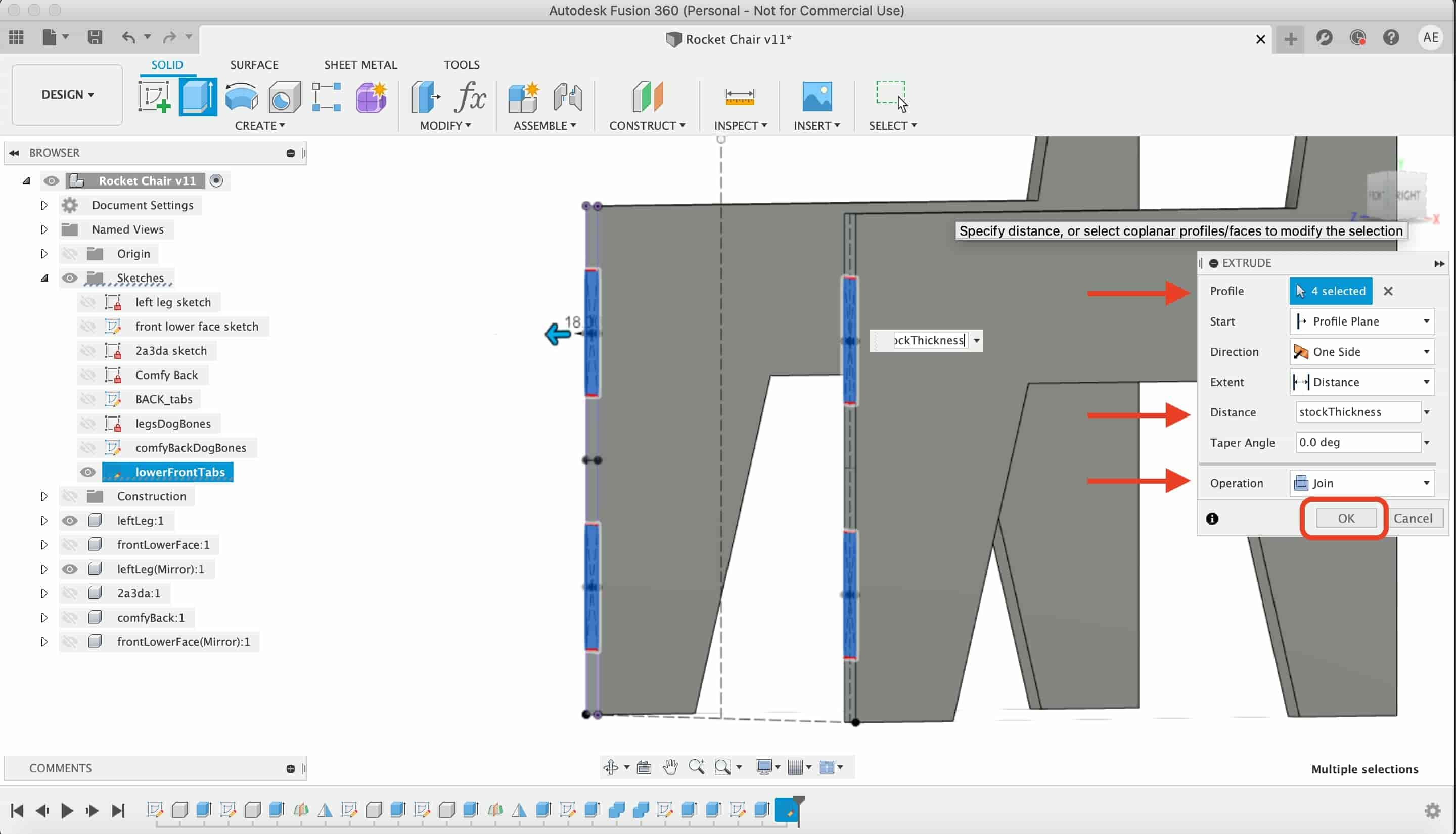
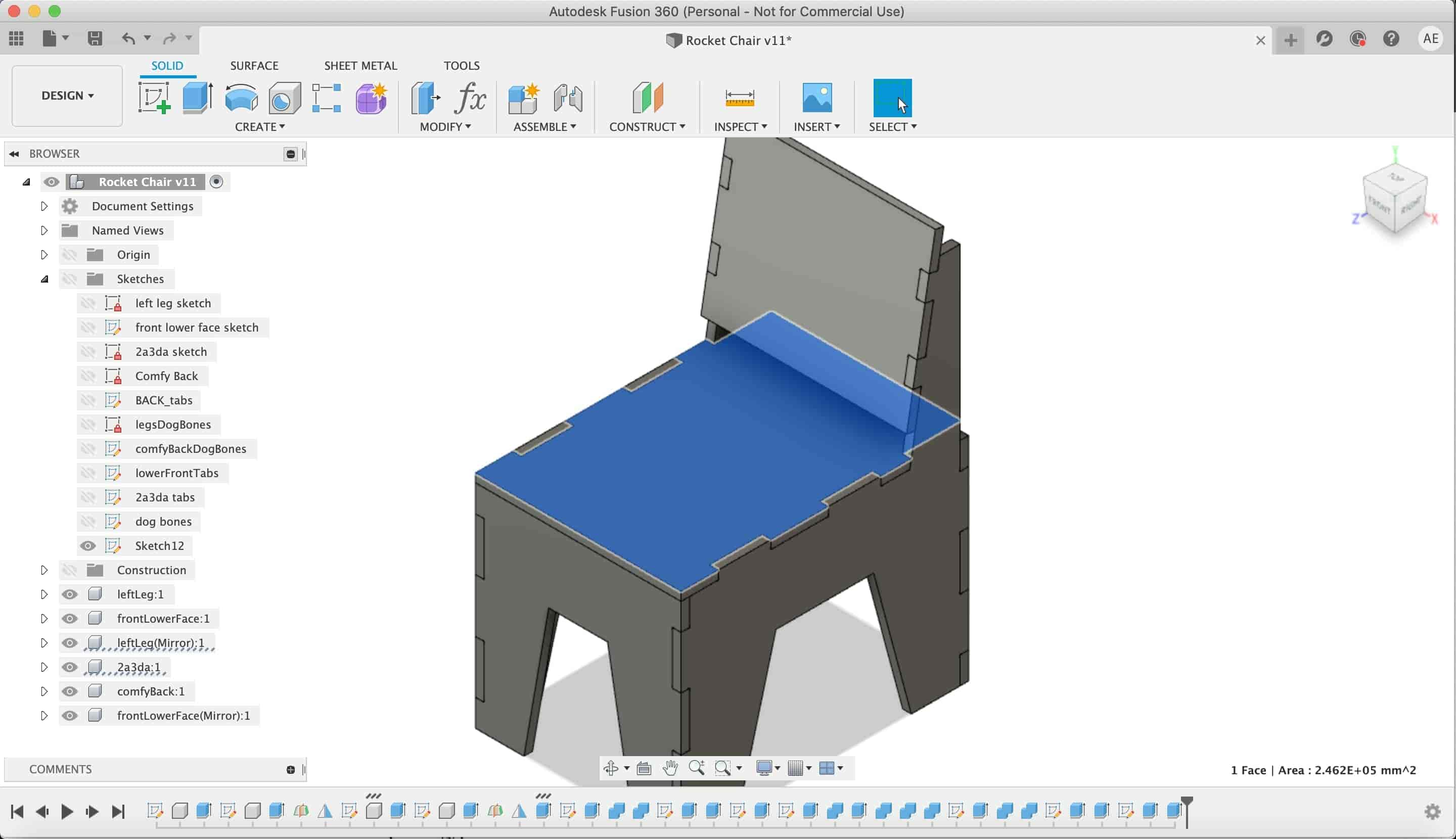
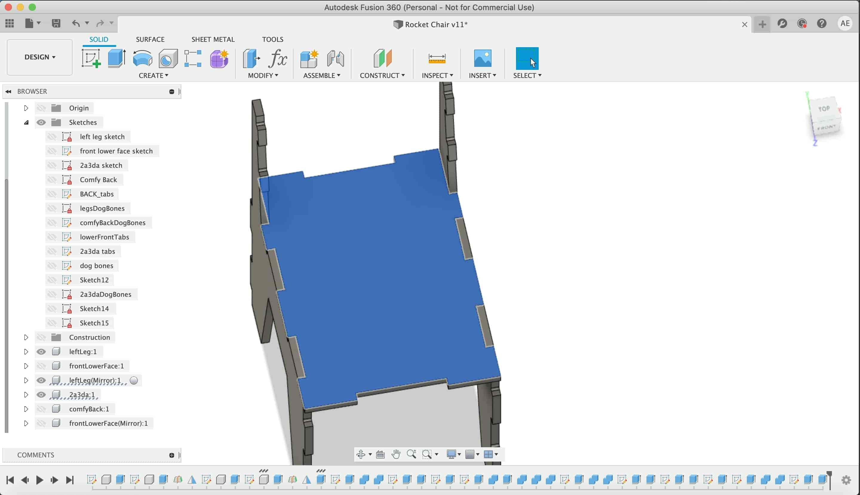
Now, let’s draw the chair seat, I drew a rectangle taking the width and the depth of the chair on the front lower leg face.
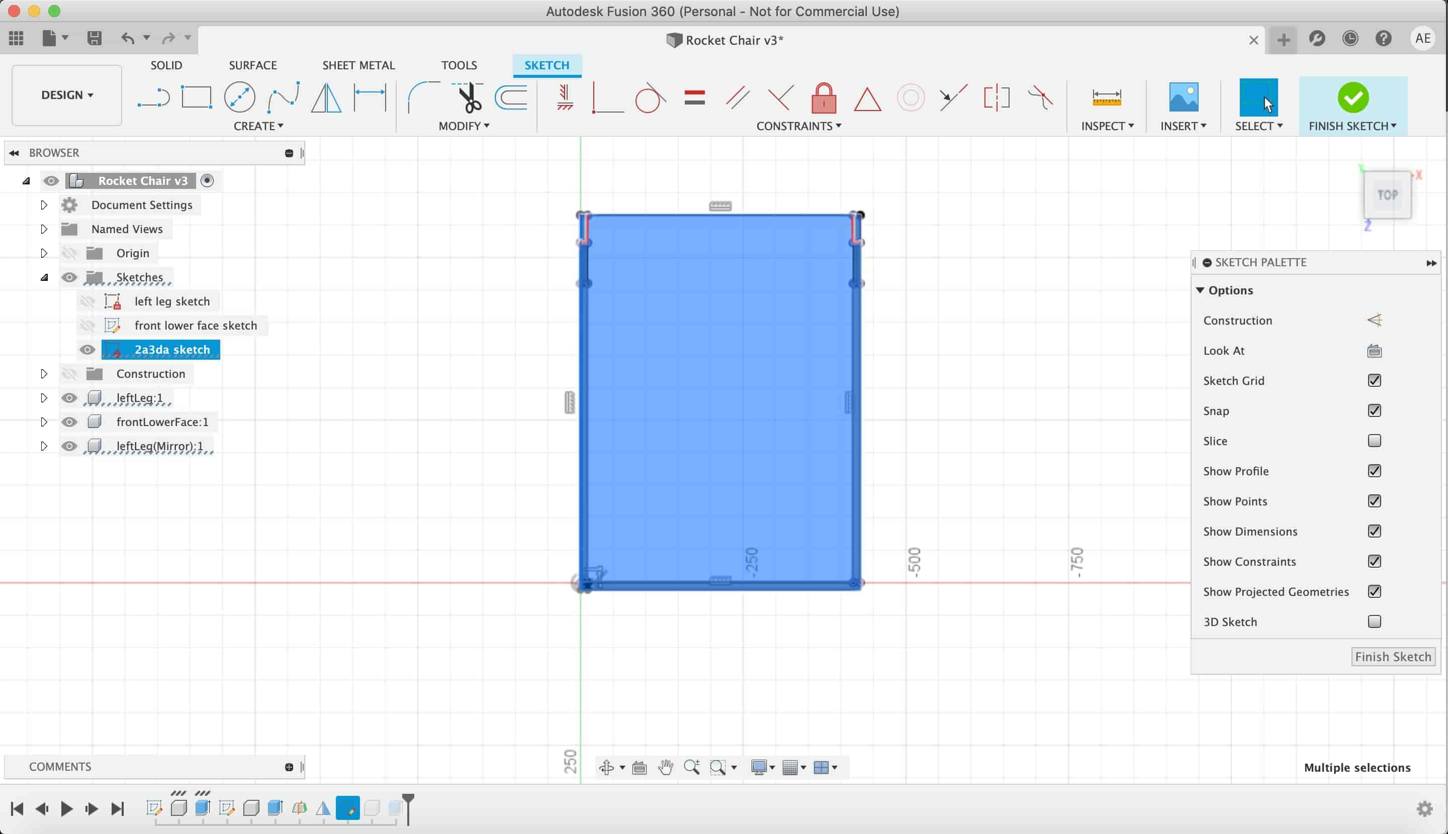
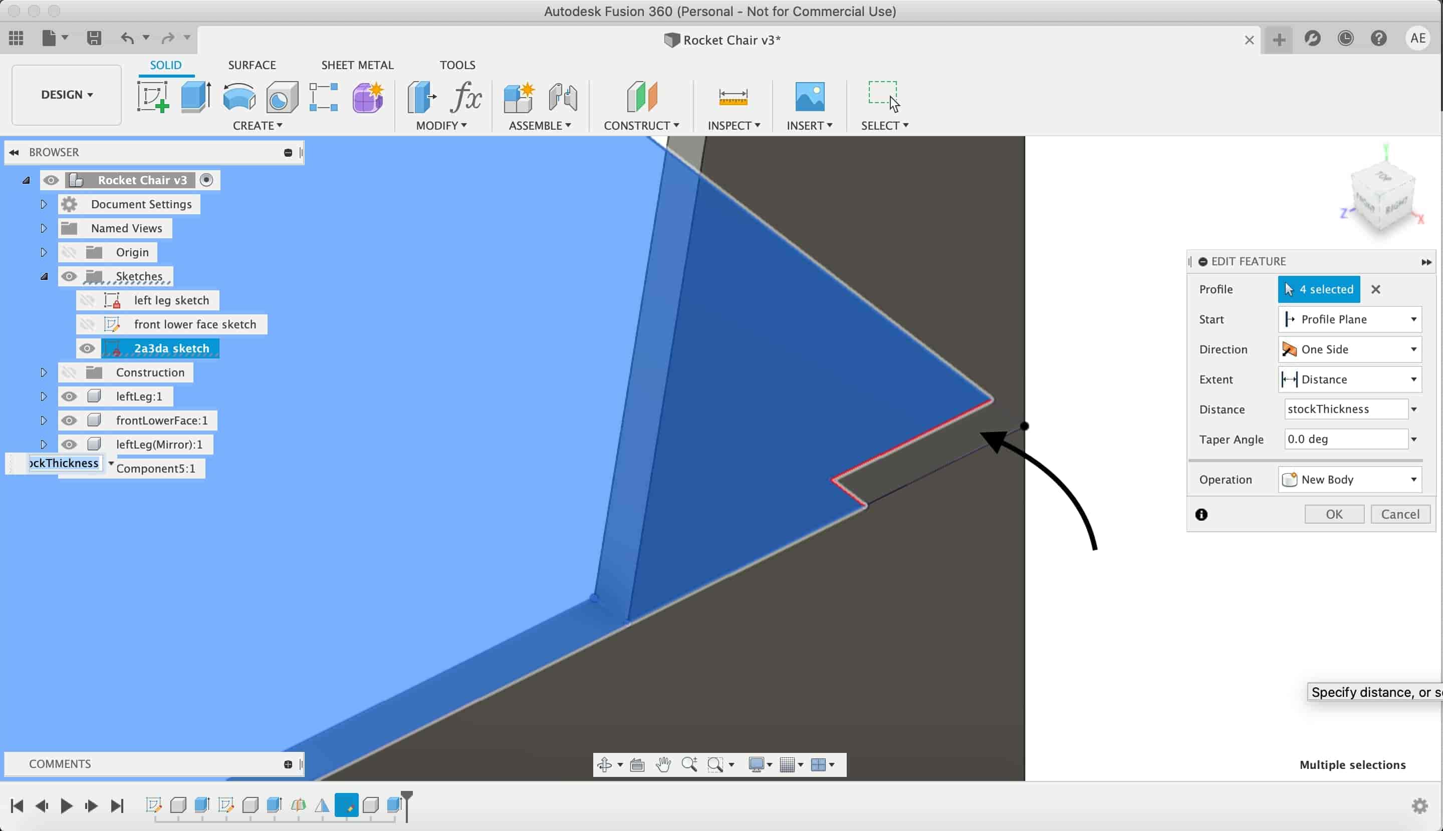
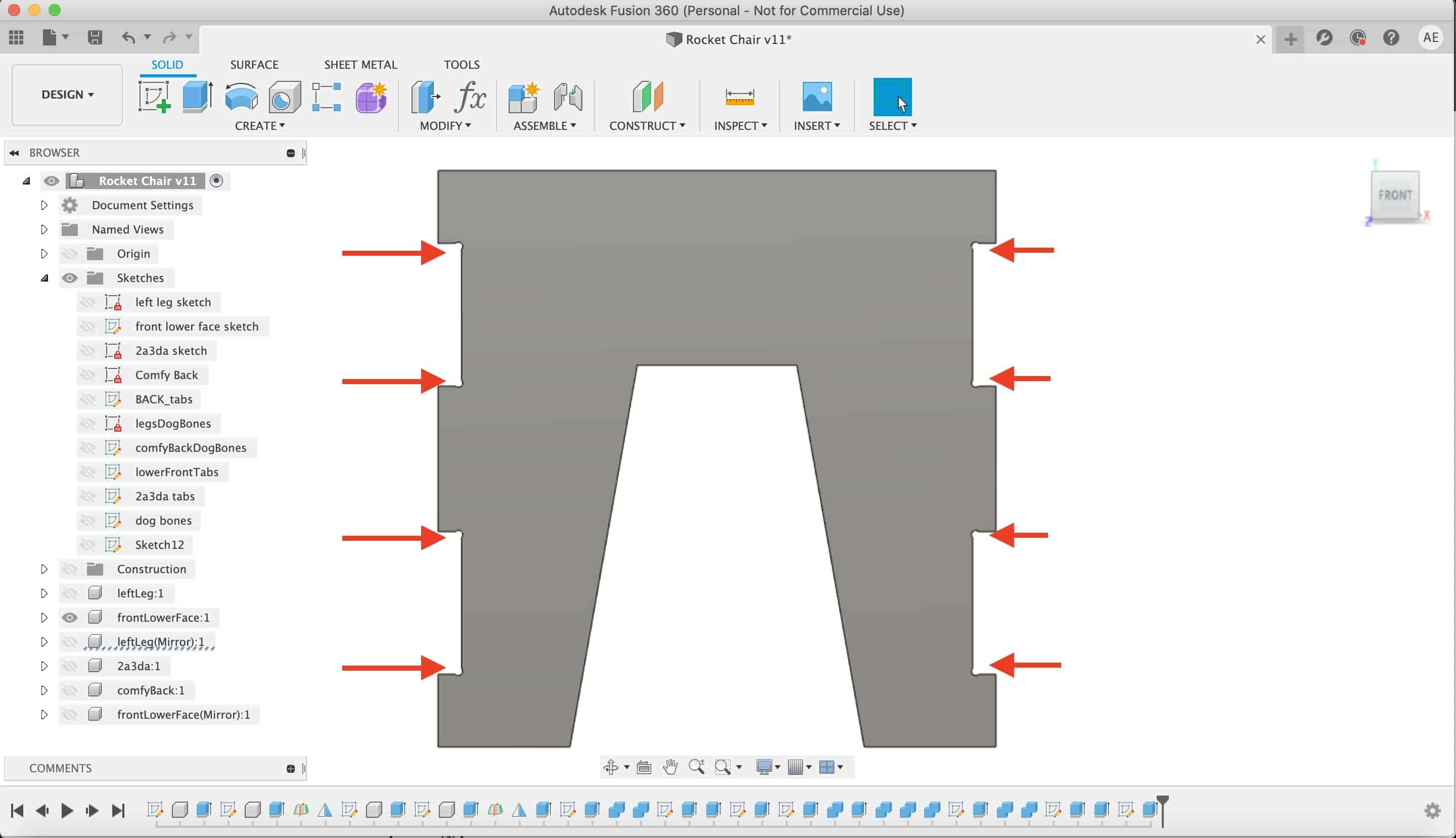
Then I extruded that rectangle with the stock thickness. Don’t forget to deselect these two small rectangles at the end of the seat.
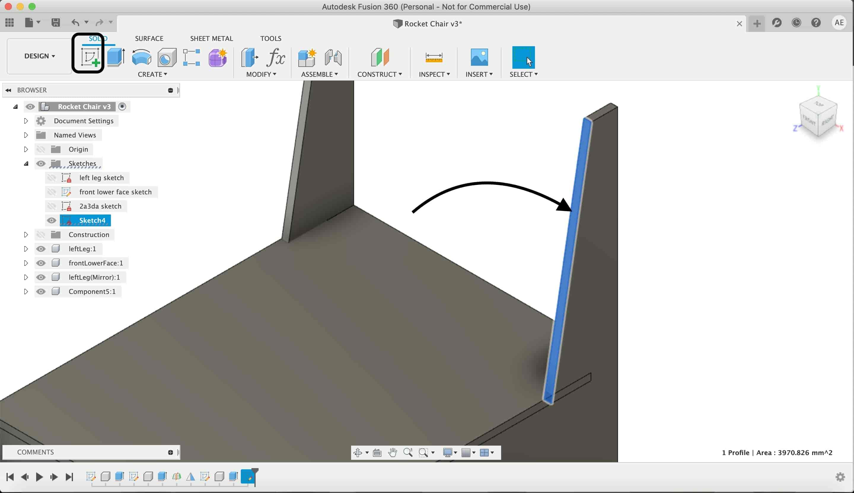
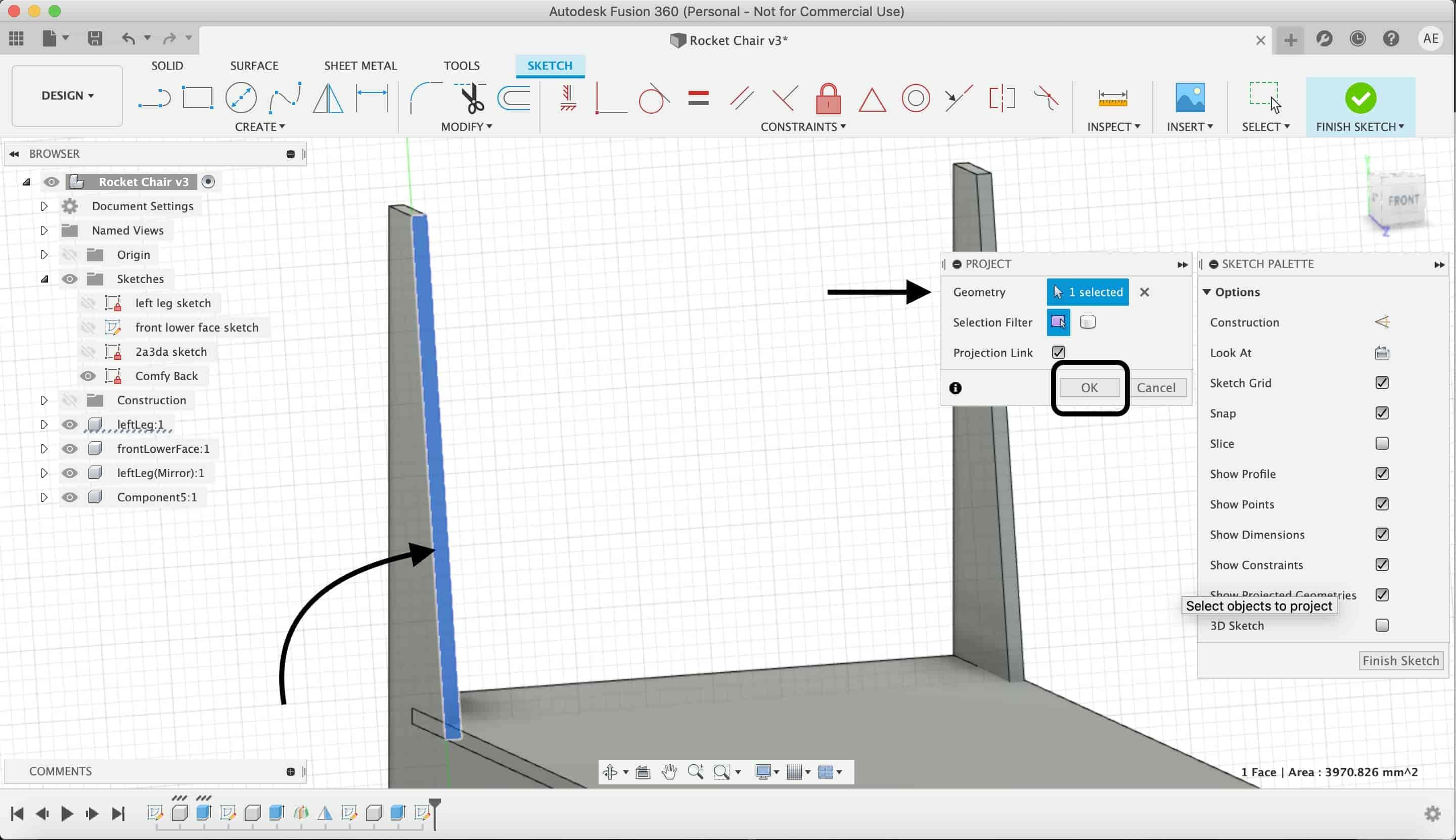
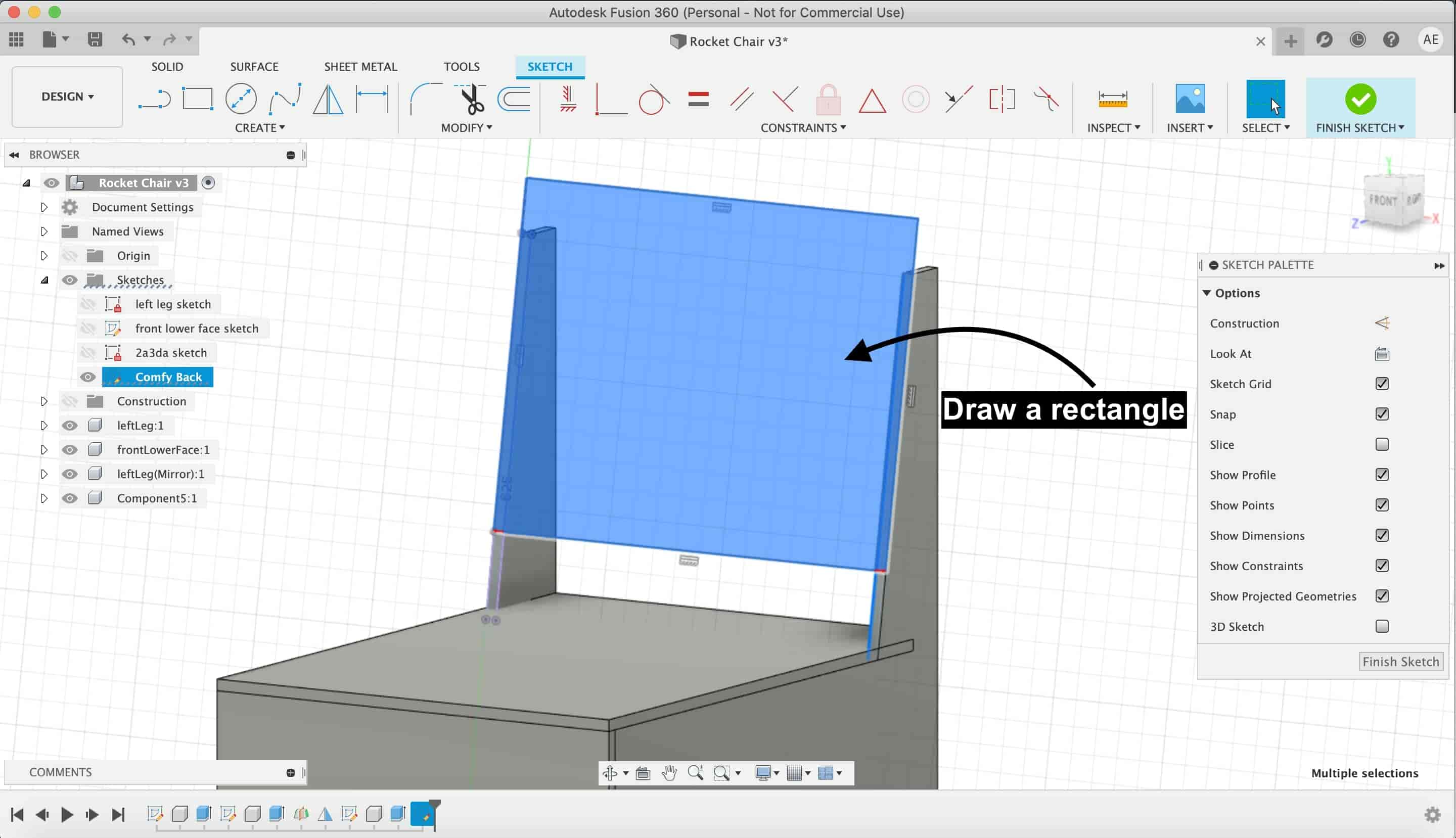
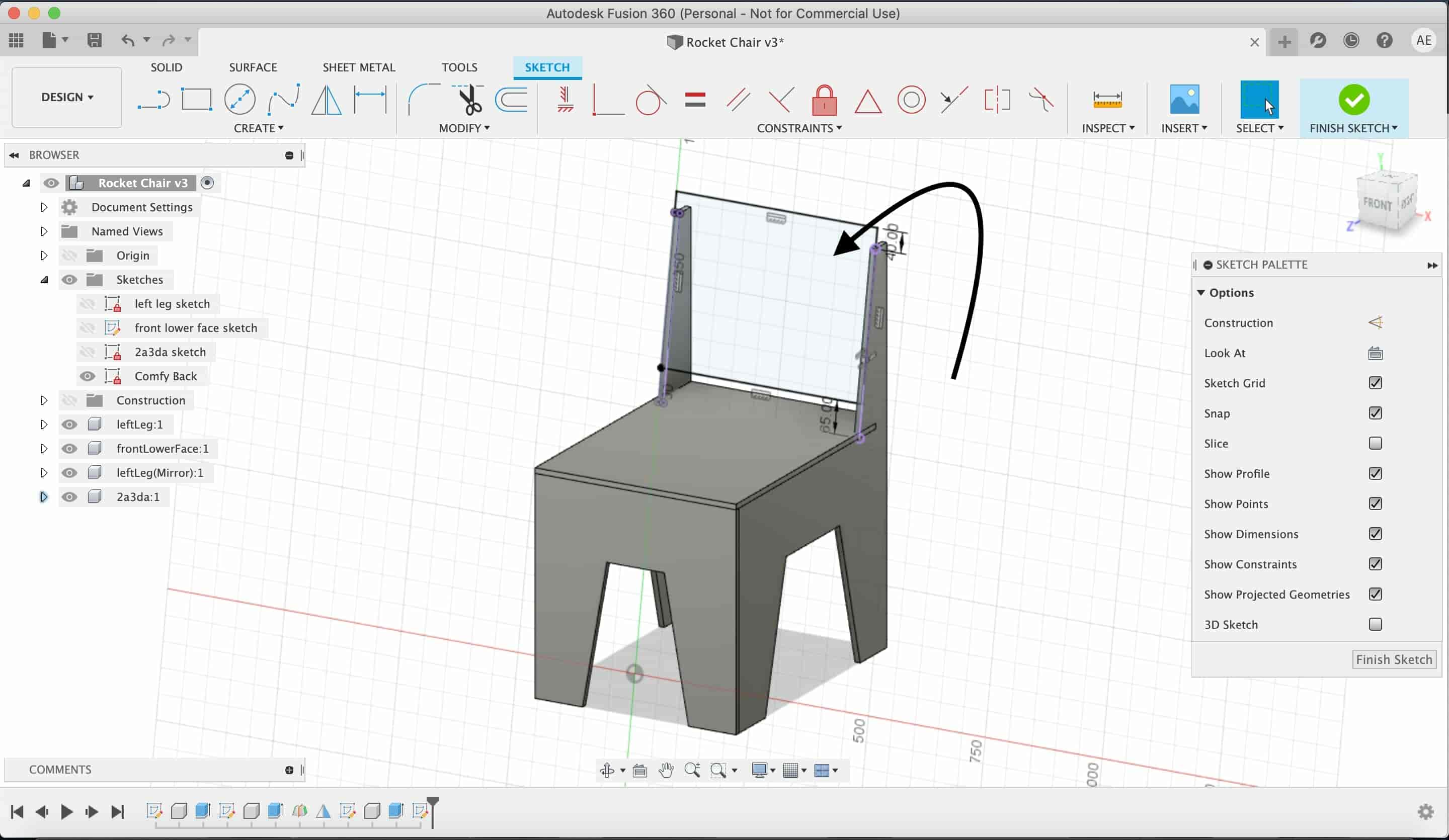
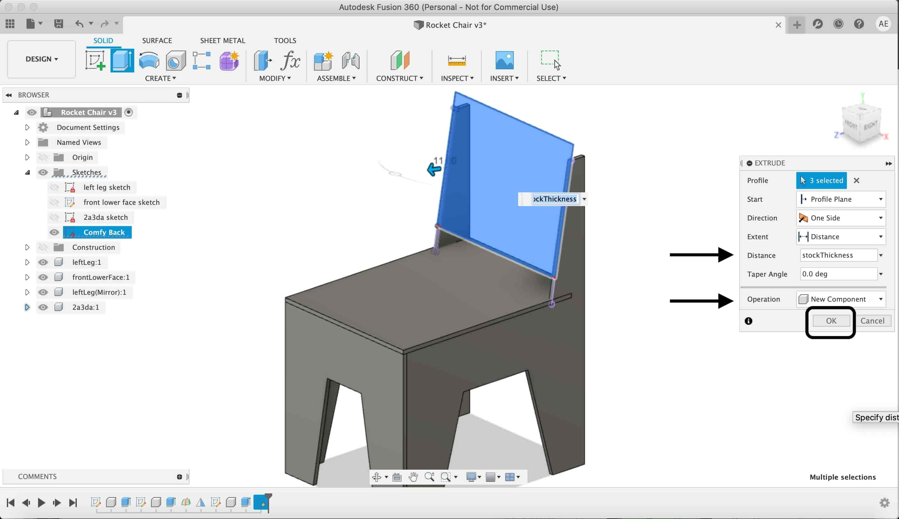
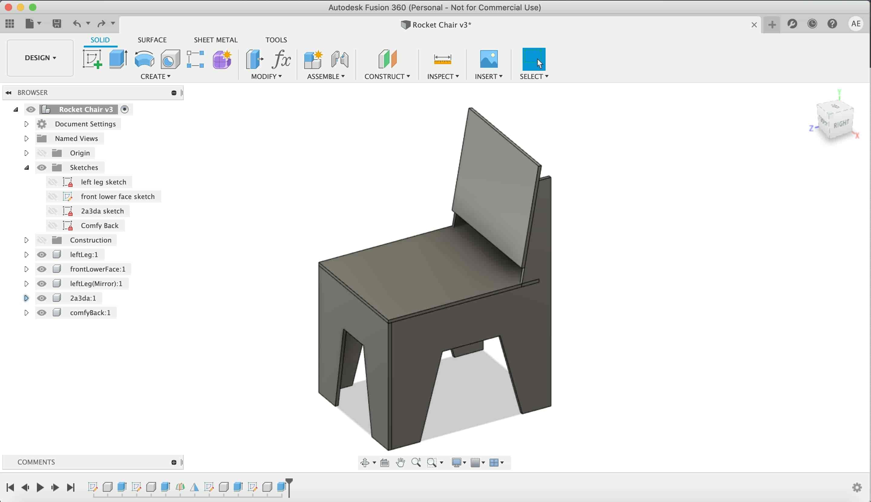
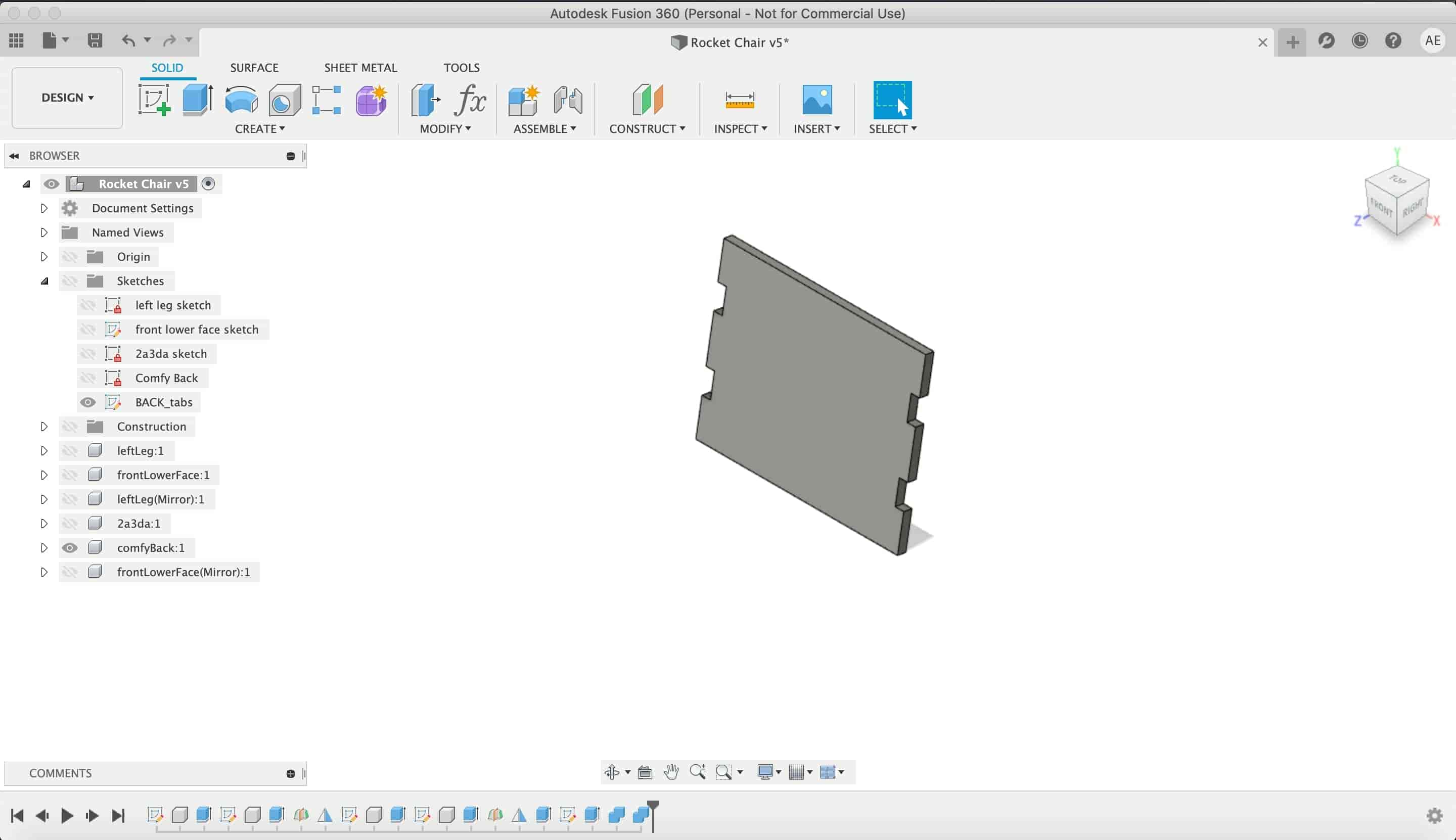
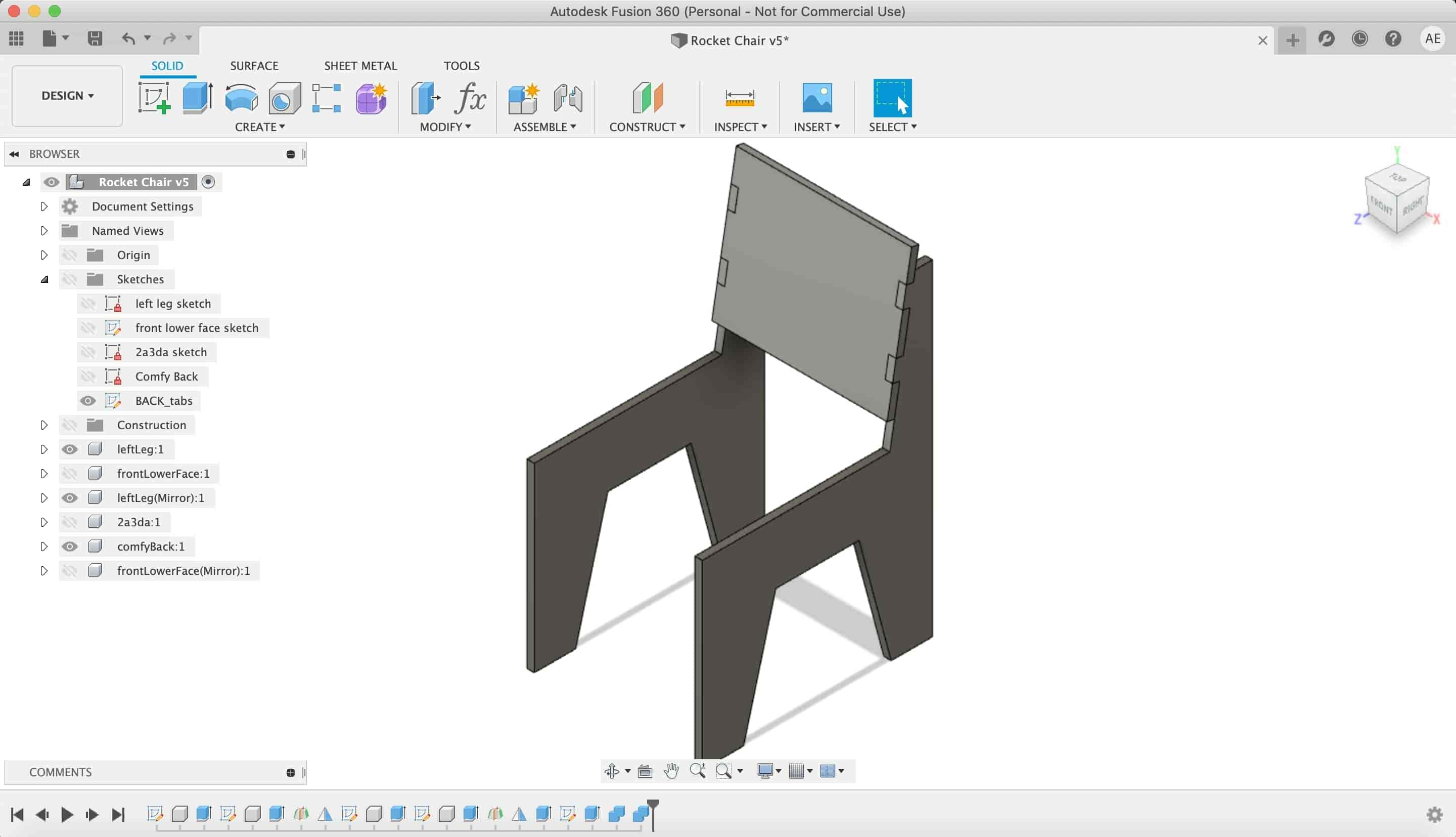
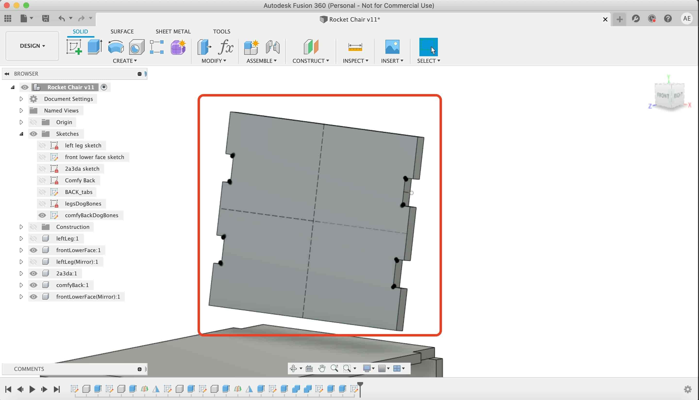
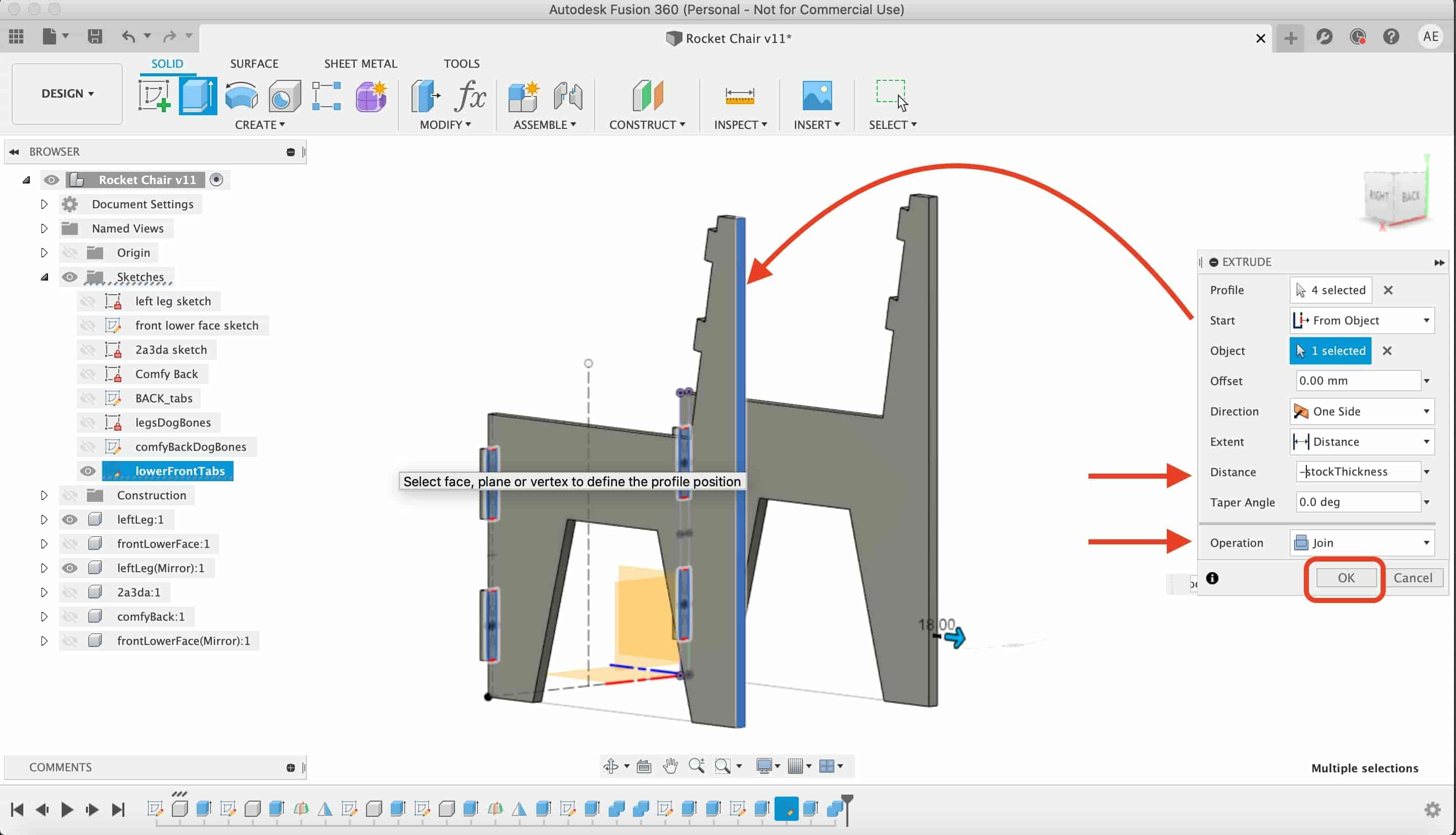
To draw the chair back, we started a new sketch and draw a rectangle and extruded it with the stock thickness.
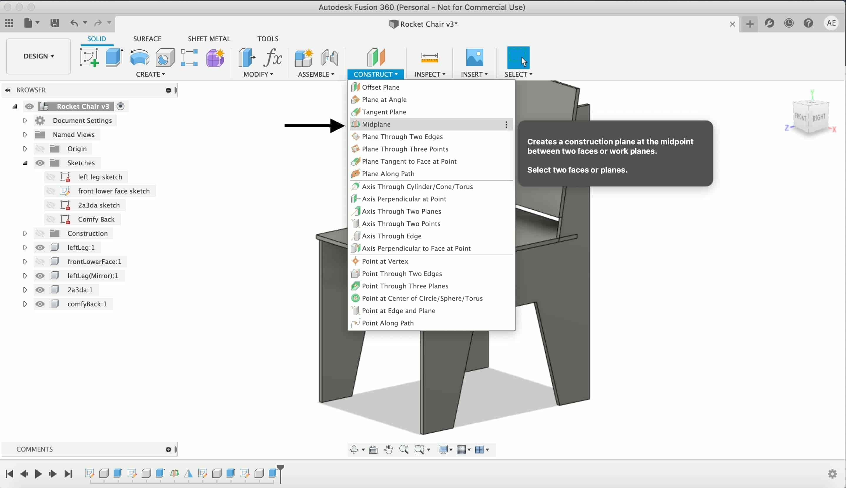
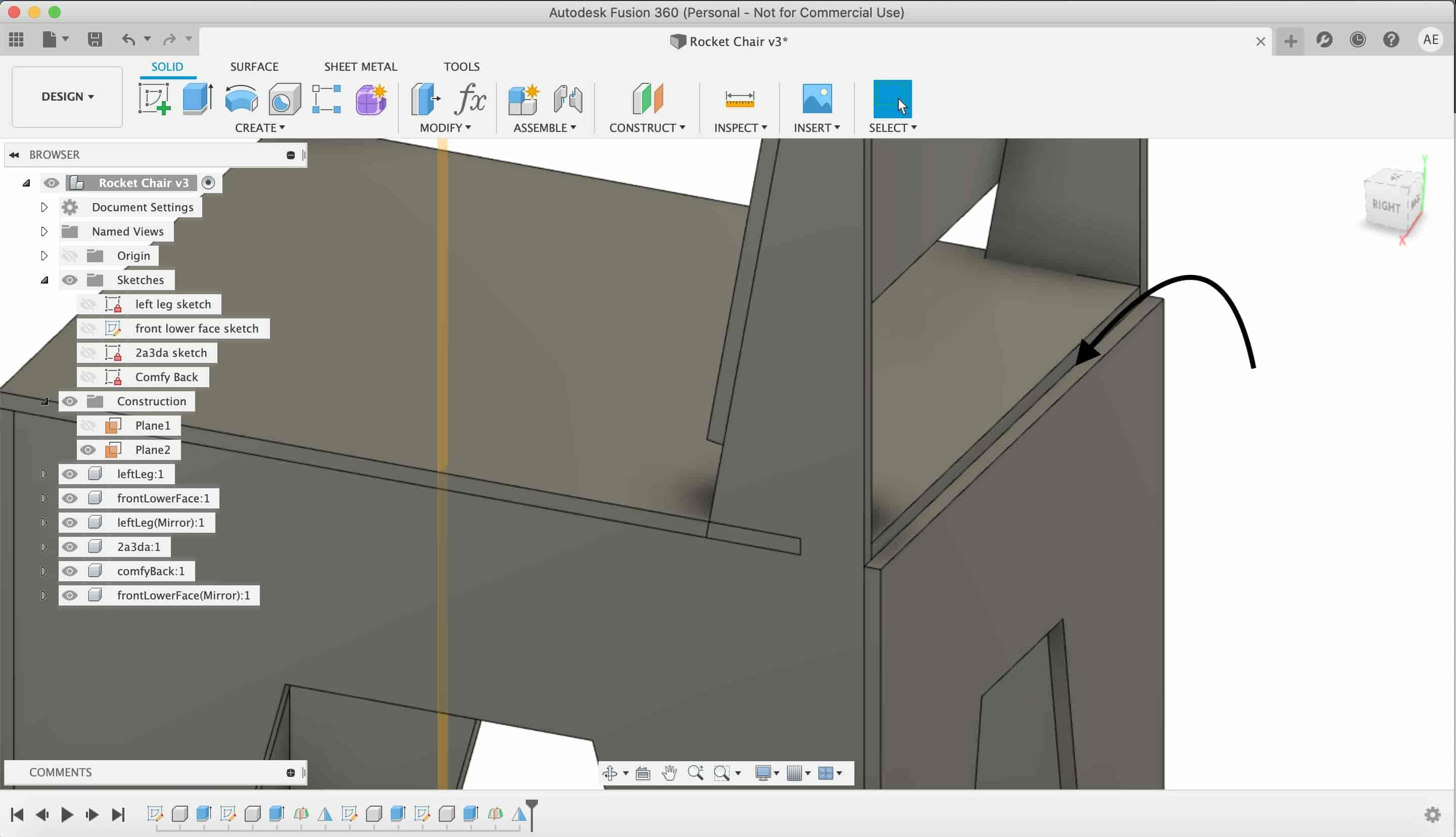
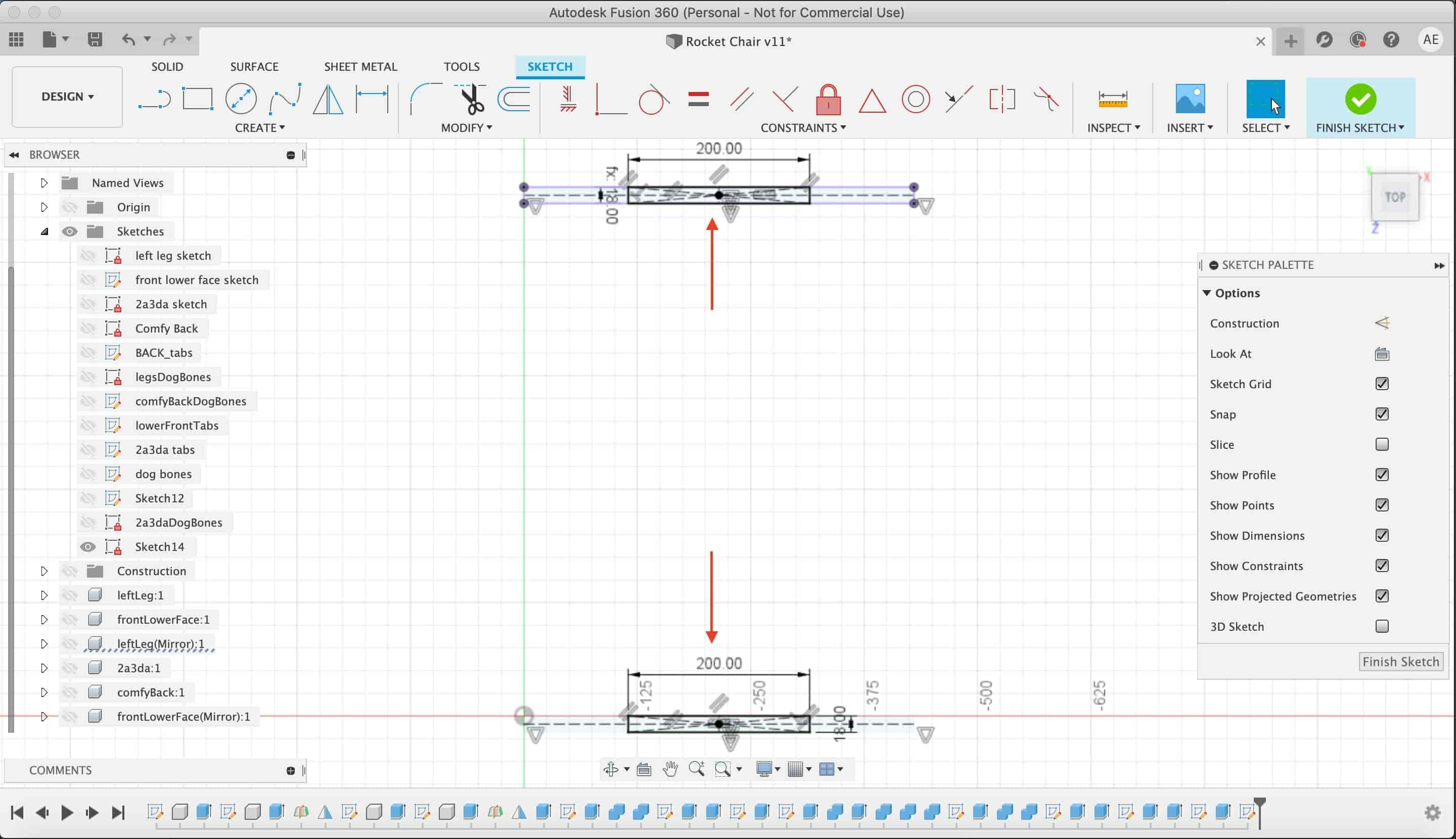
Now we need to mirror the front lower face leg to make another copy on the back of the chair. We made a midplane and mirrored the front lowe face leg.
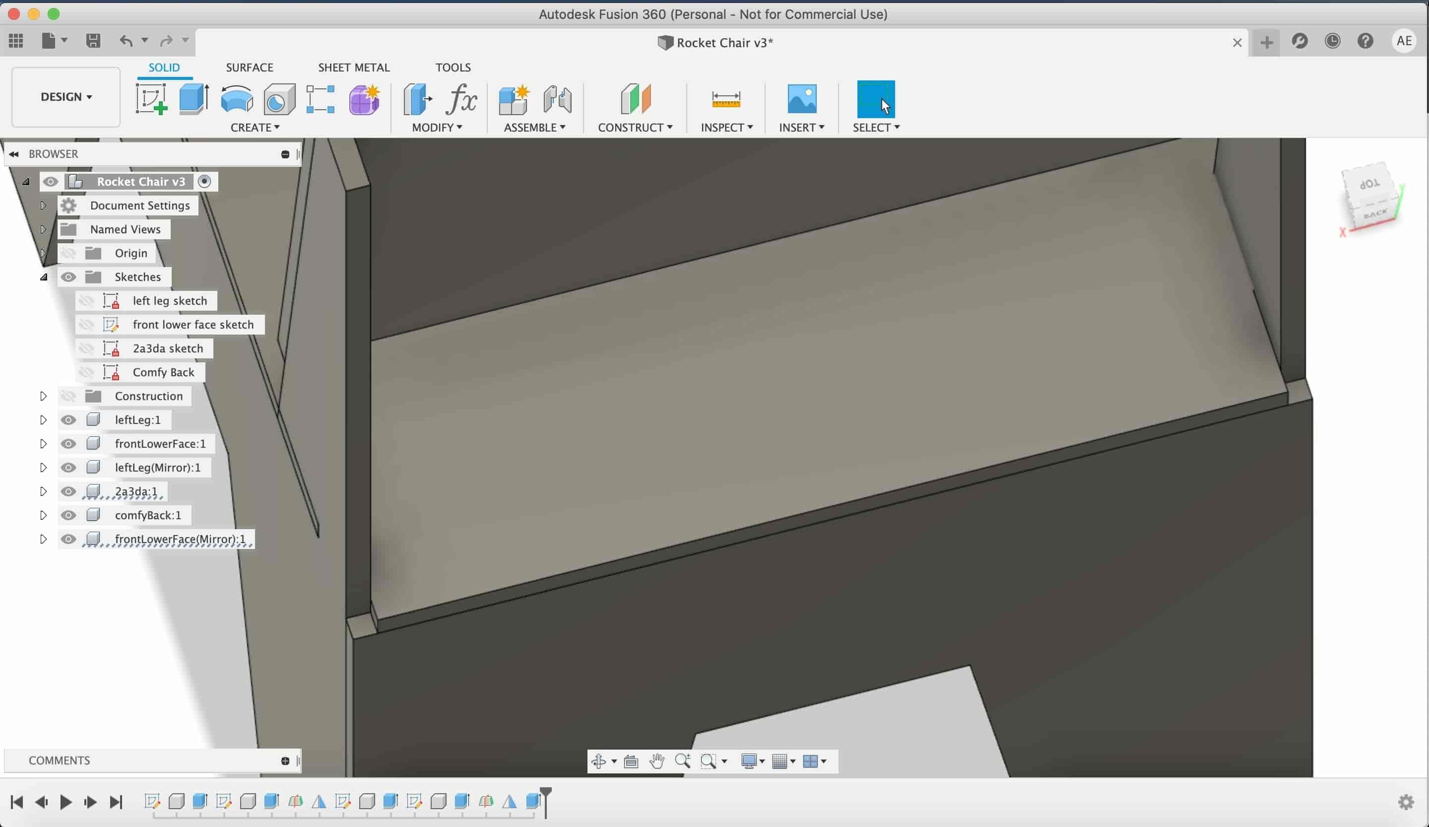
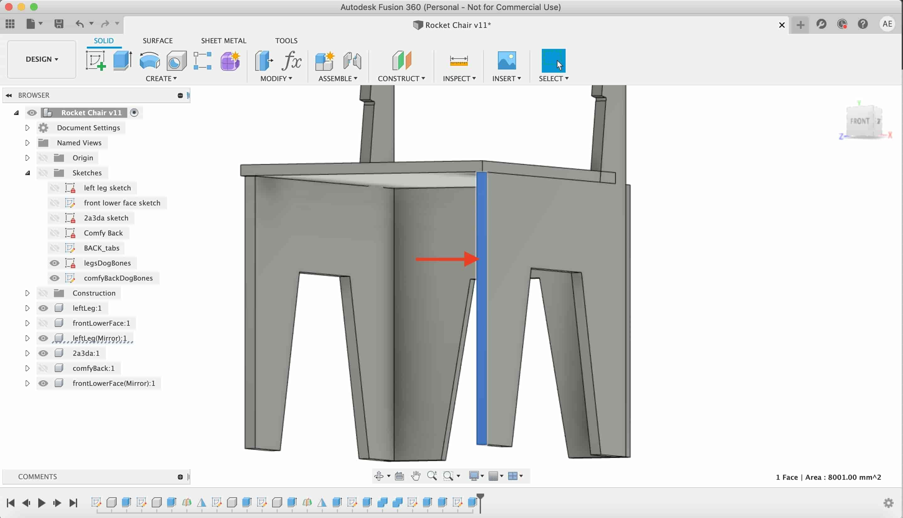
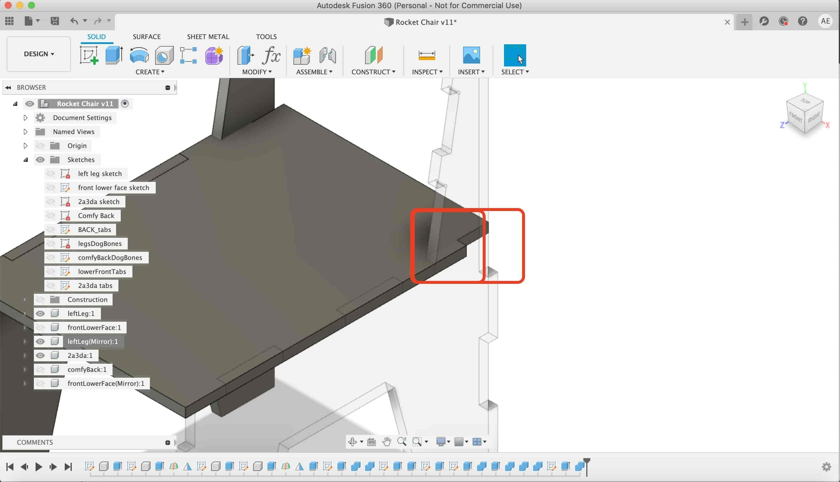
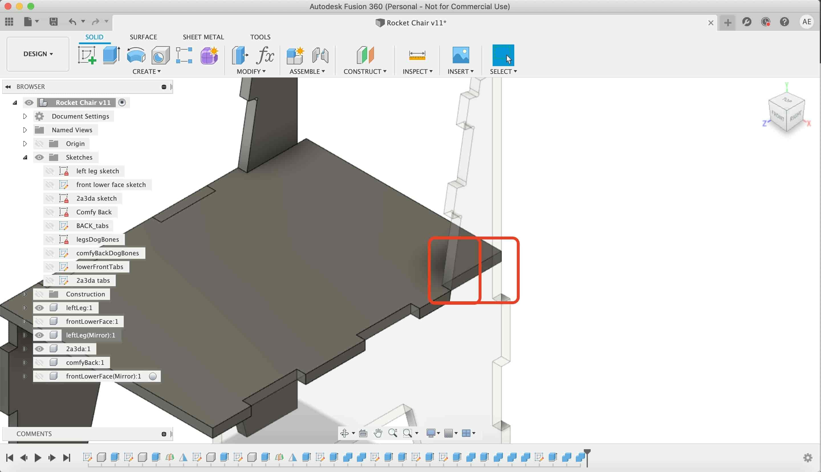
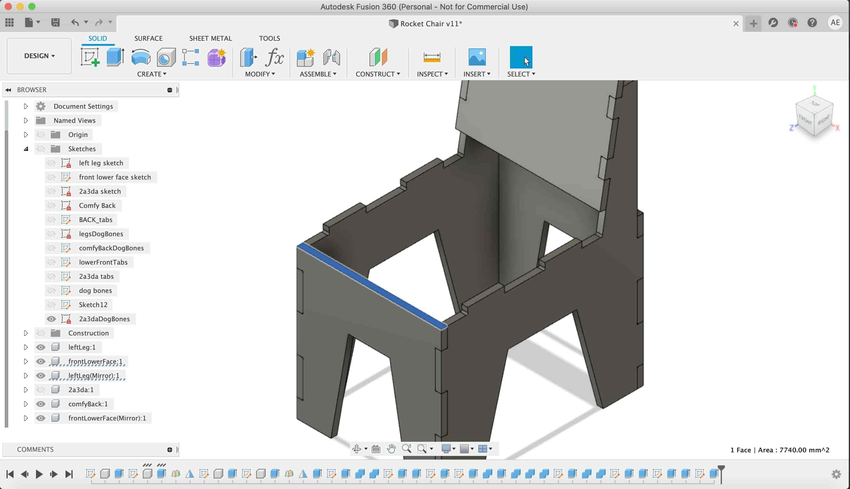
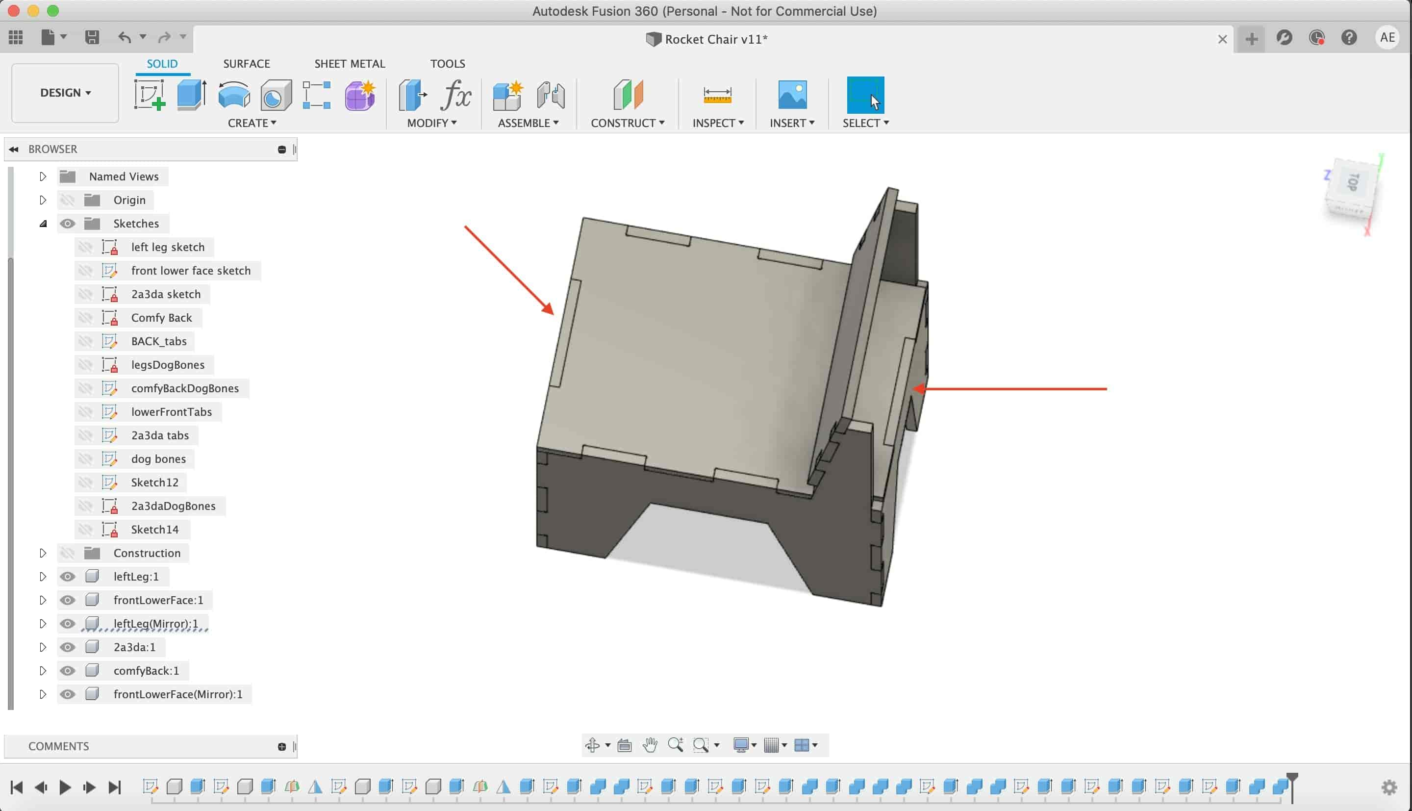
I noticed a small problem. The chair seat and the back lower leg do not look very symmetric. So, I extruded the chair seat to cover that part. It looks more nice now.
At this point, we finished the chair structure but without any joints to keep all these parts together. So, I did a little research on how to design joints especially for CNC router machines. Because there are some considerations we have to put in mind when we design for a CNC router machine. I found this great video that explains joint types and how to design each one in a simple and clear way made especially for CNC router machines. I decided to use the dogbone fillets joint.

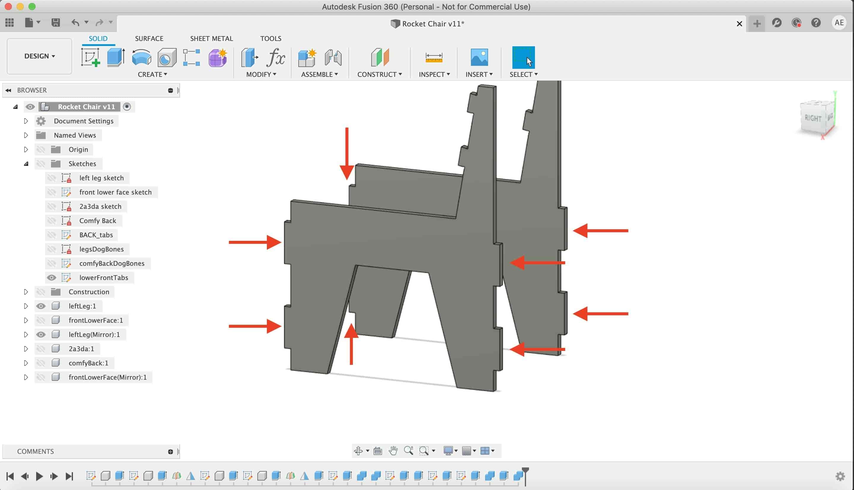
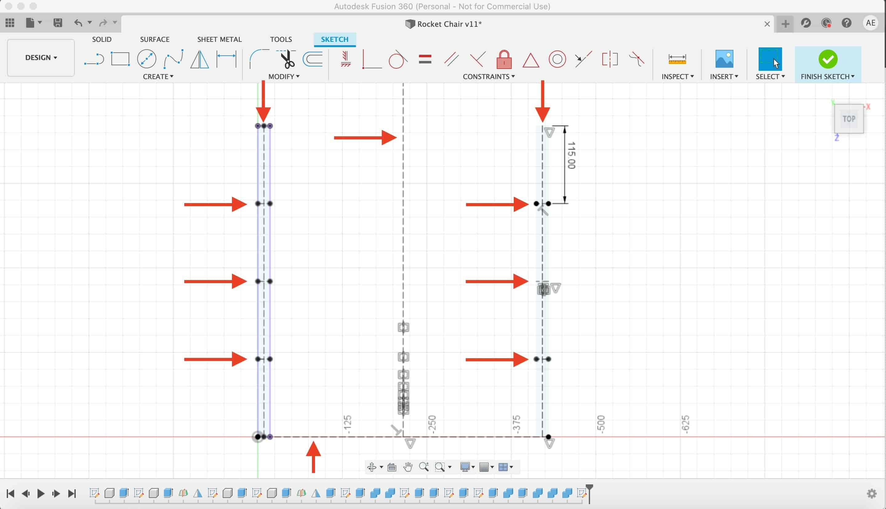
Lets do some joints now.
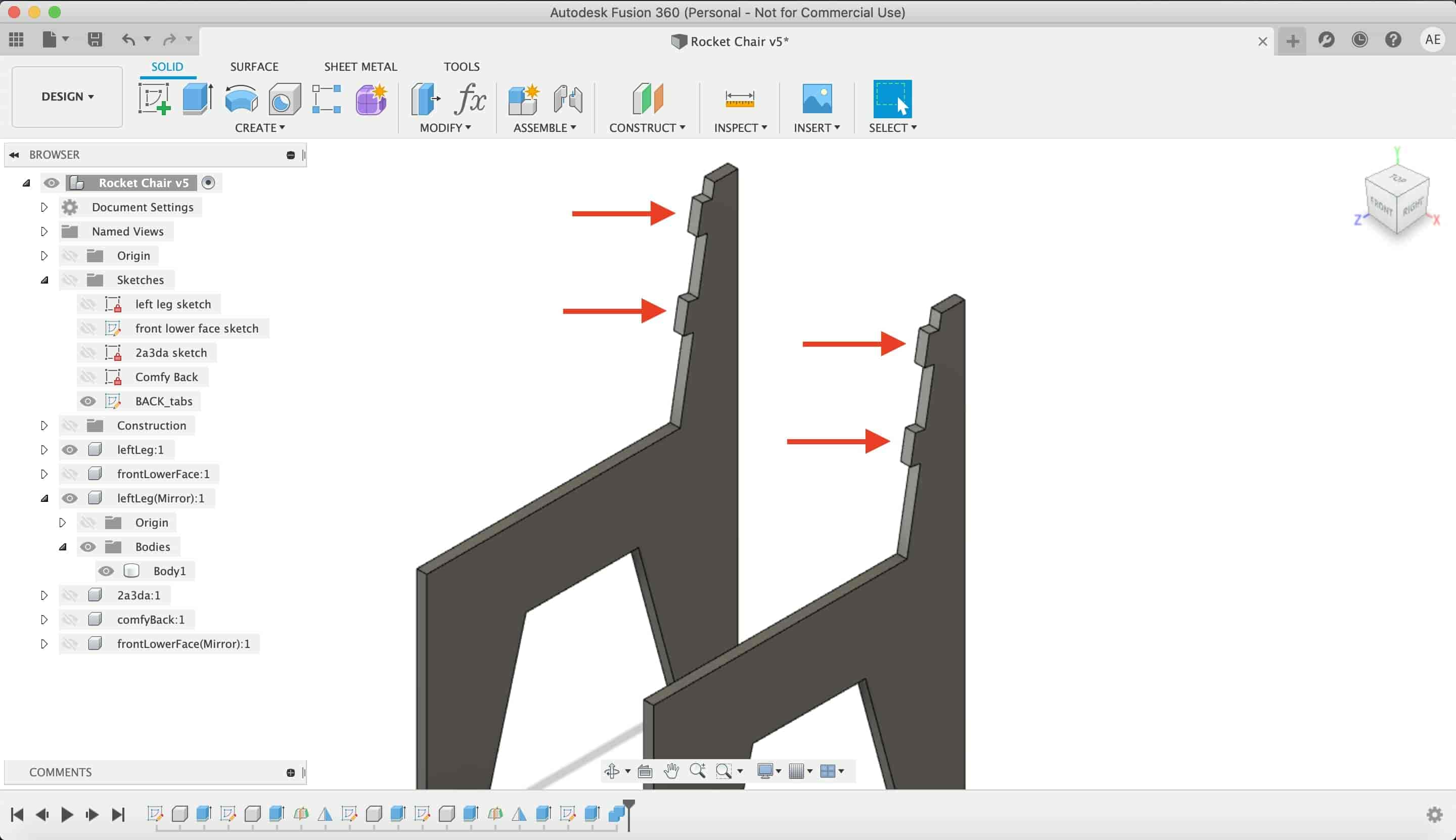
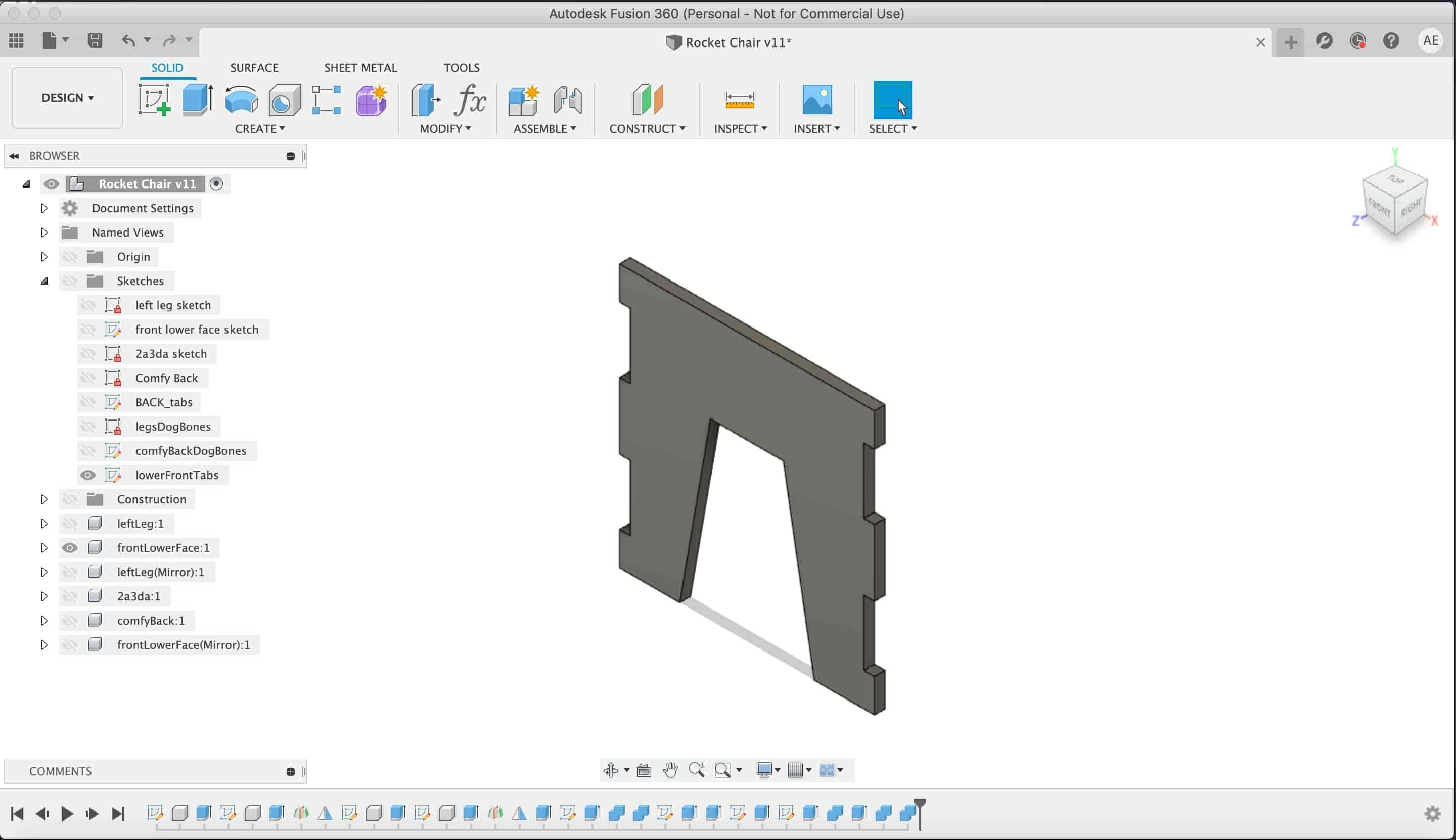
Lets make some opening in the chair back part to fit with the chair legs extrusion.
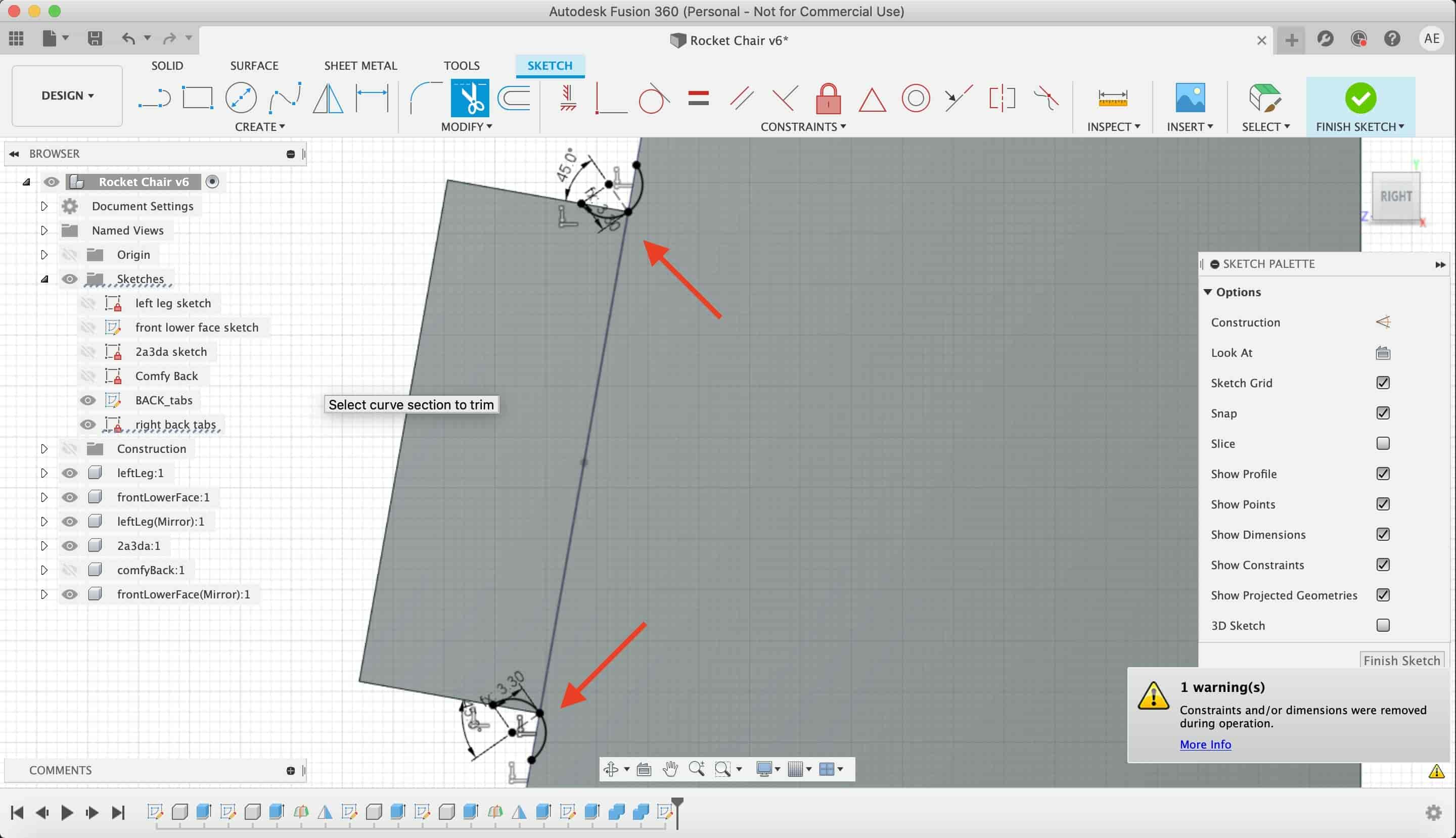
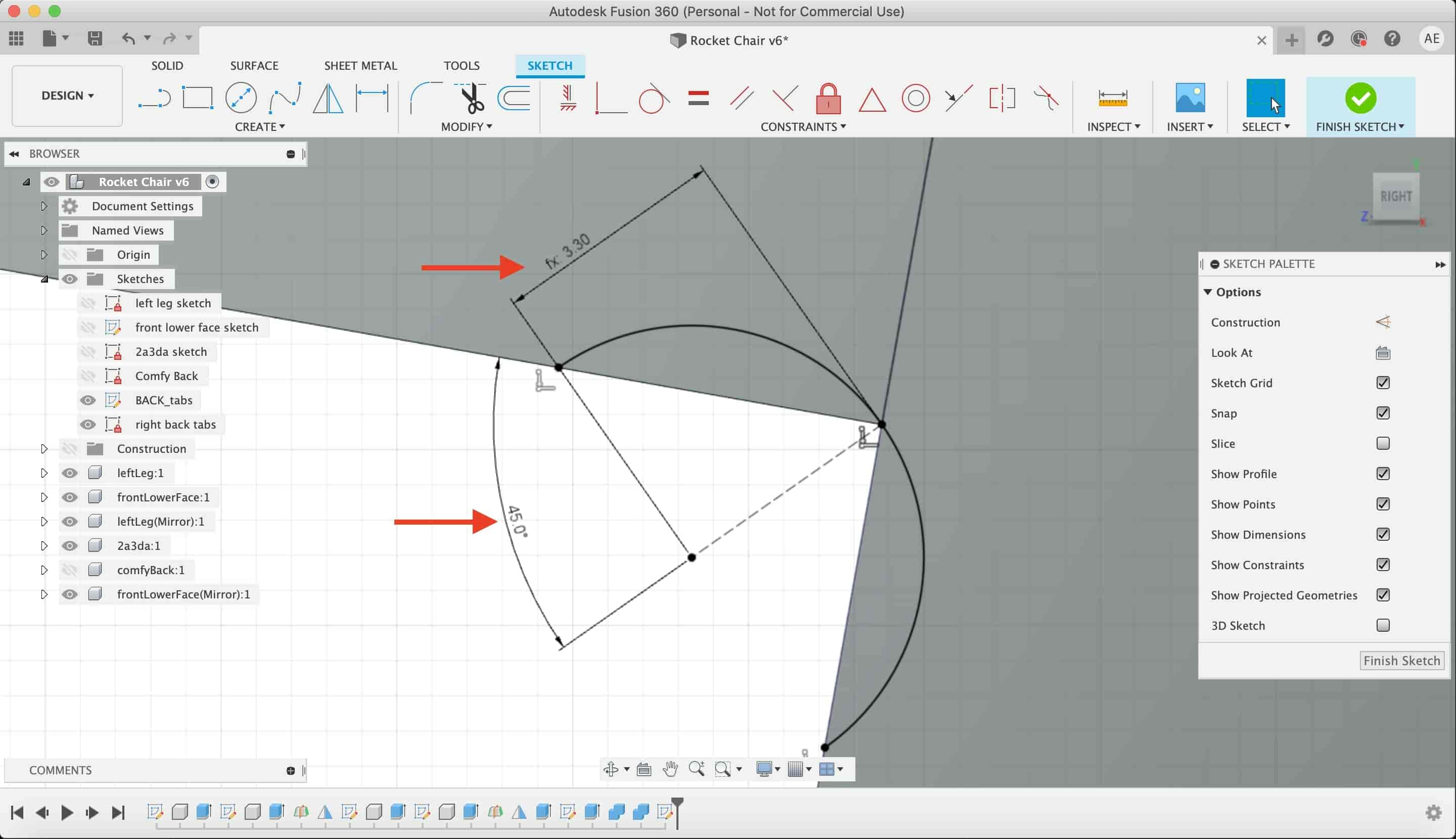
At this point, yeah we made some hammer fits but designing for CNC machining needs one more step is to put in consideration the tool movement that you will use in machining your design. You can check this video for more details in this part specifically.
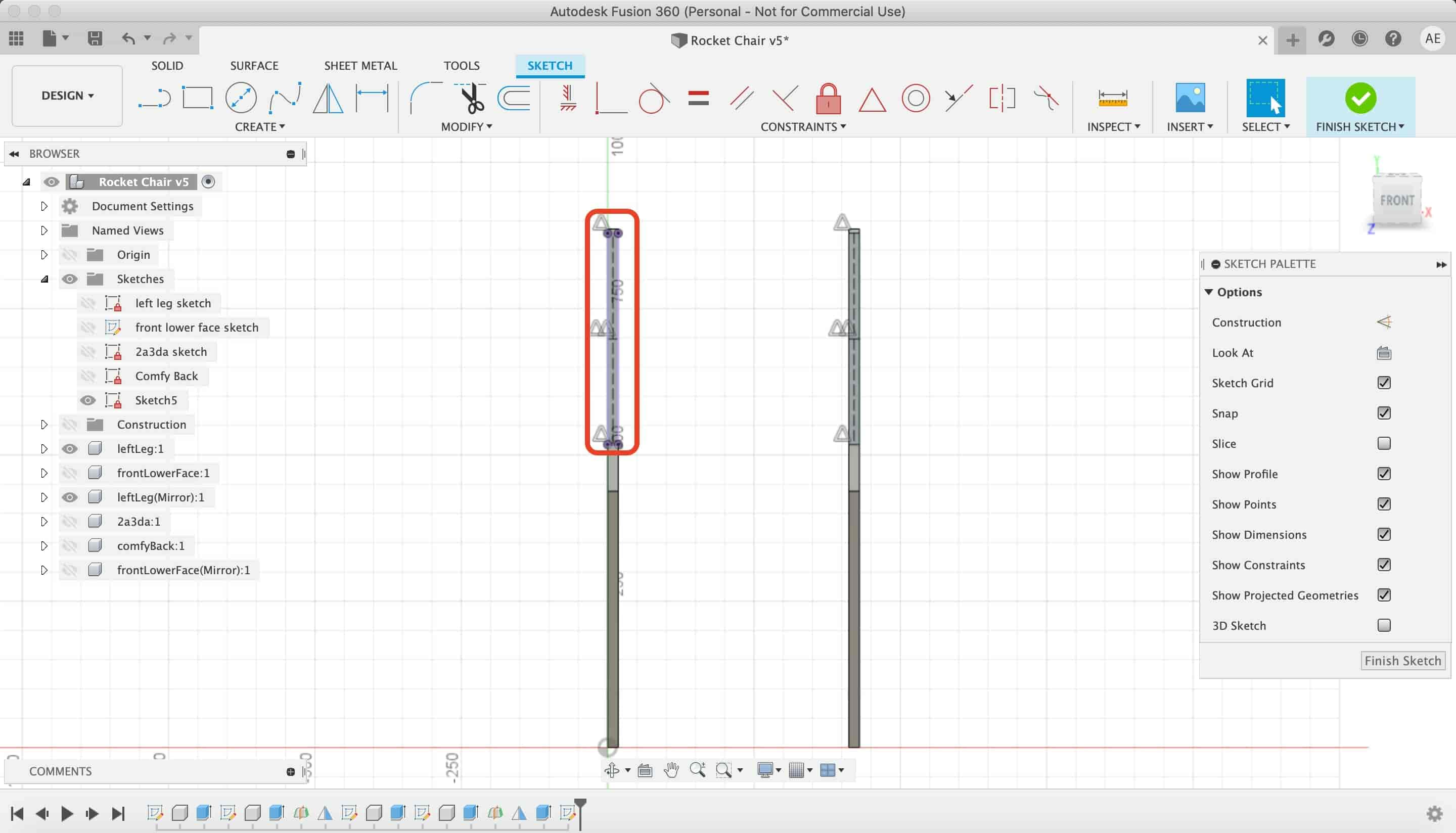
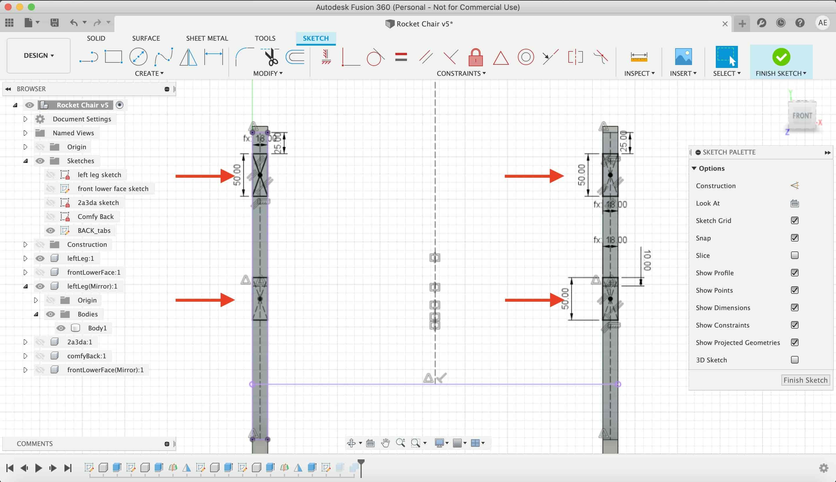
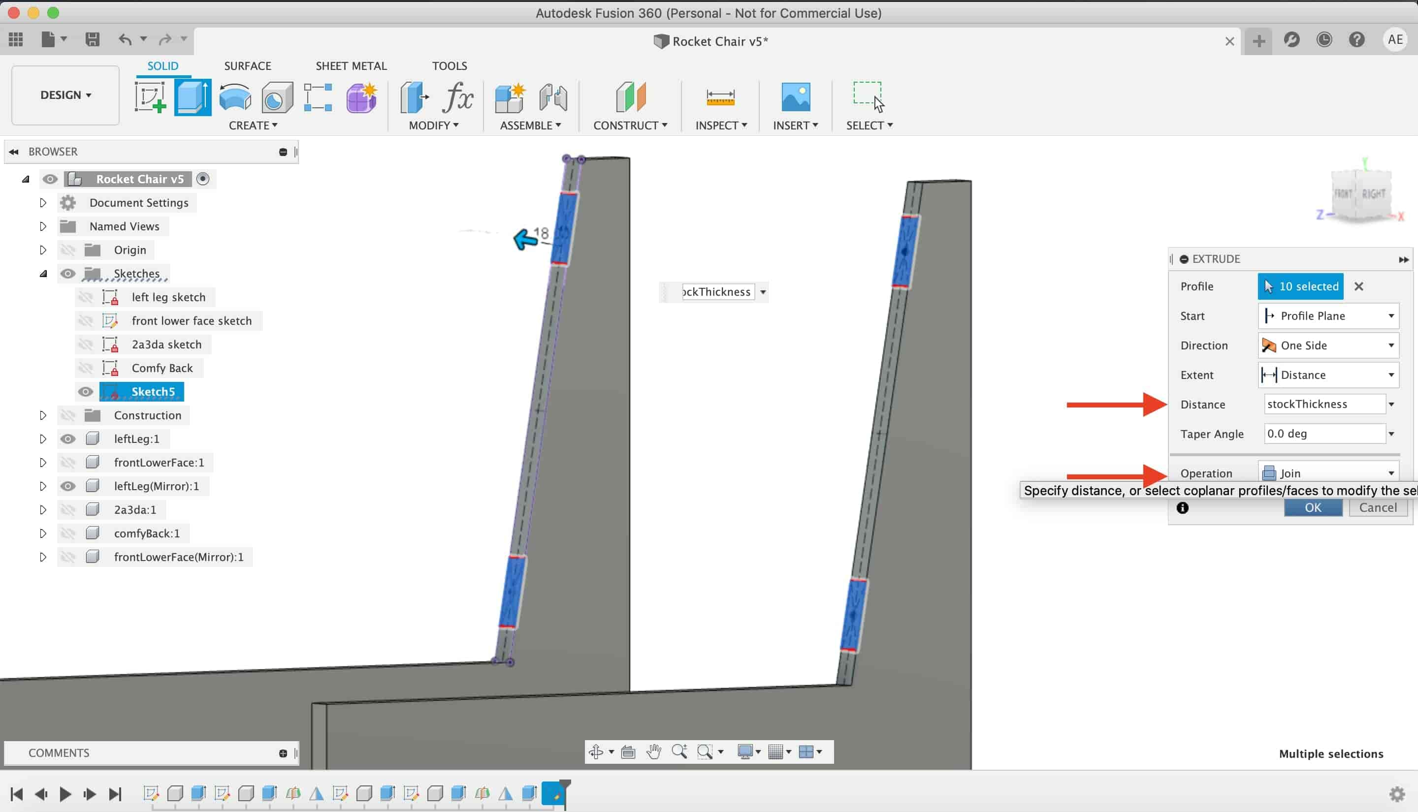
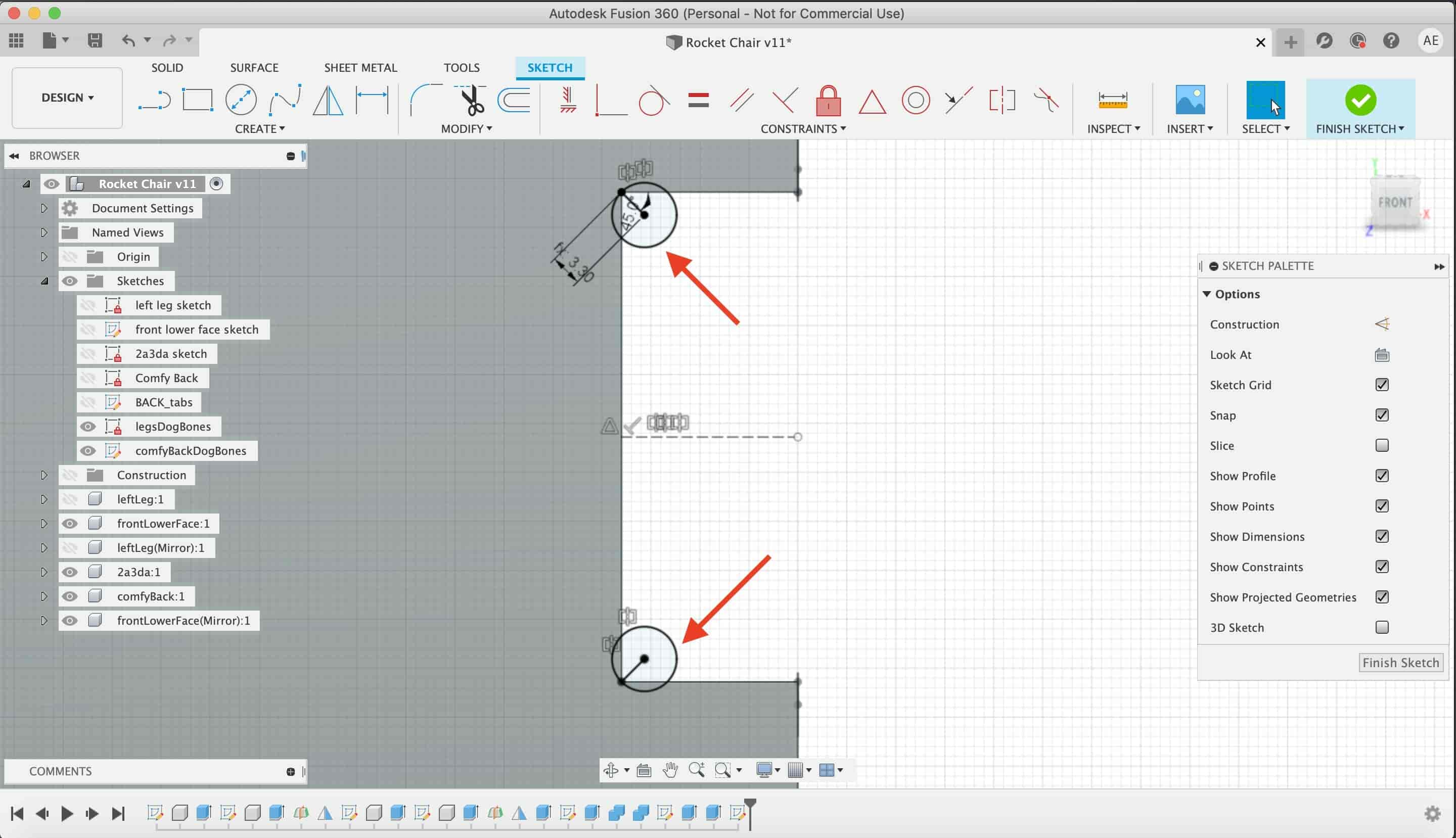
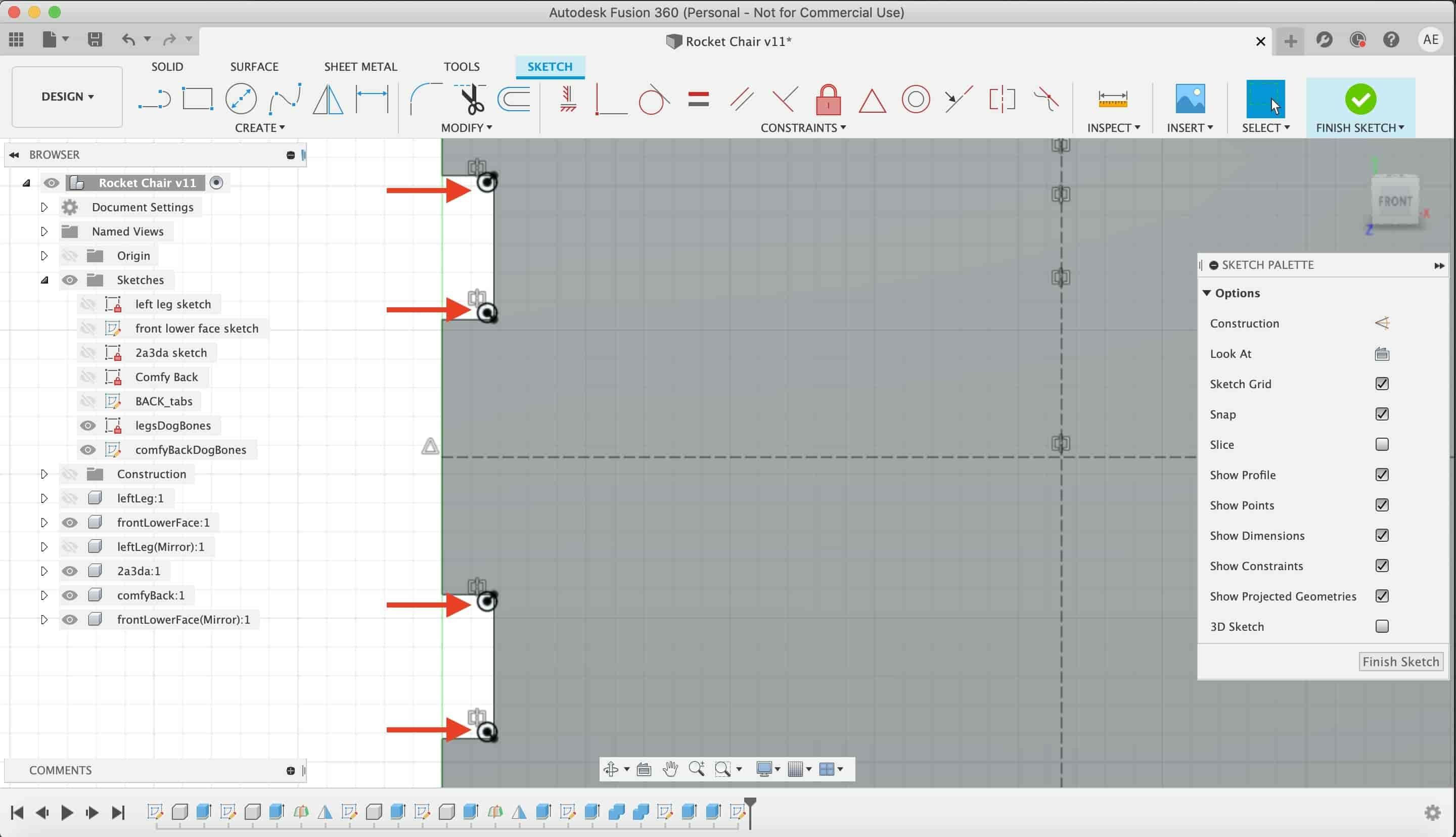
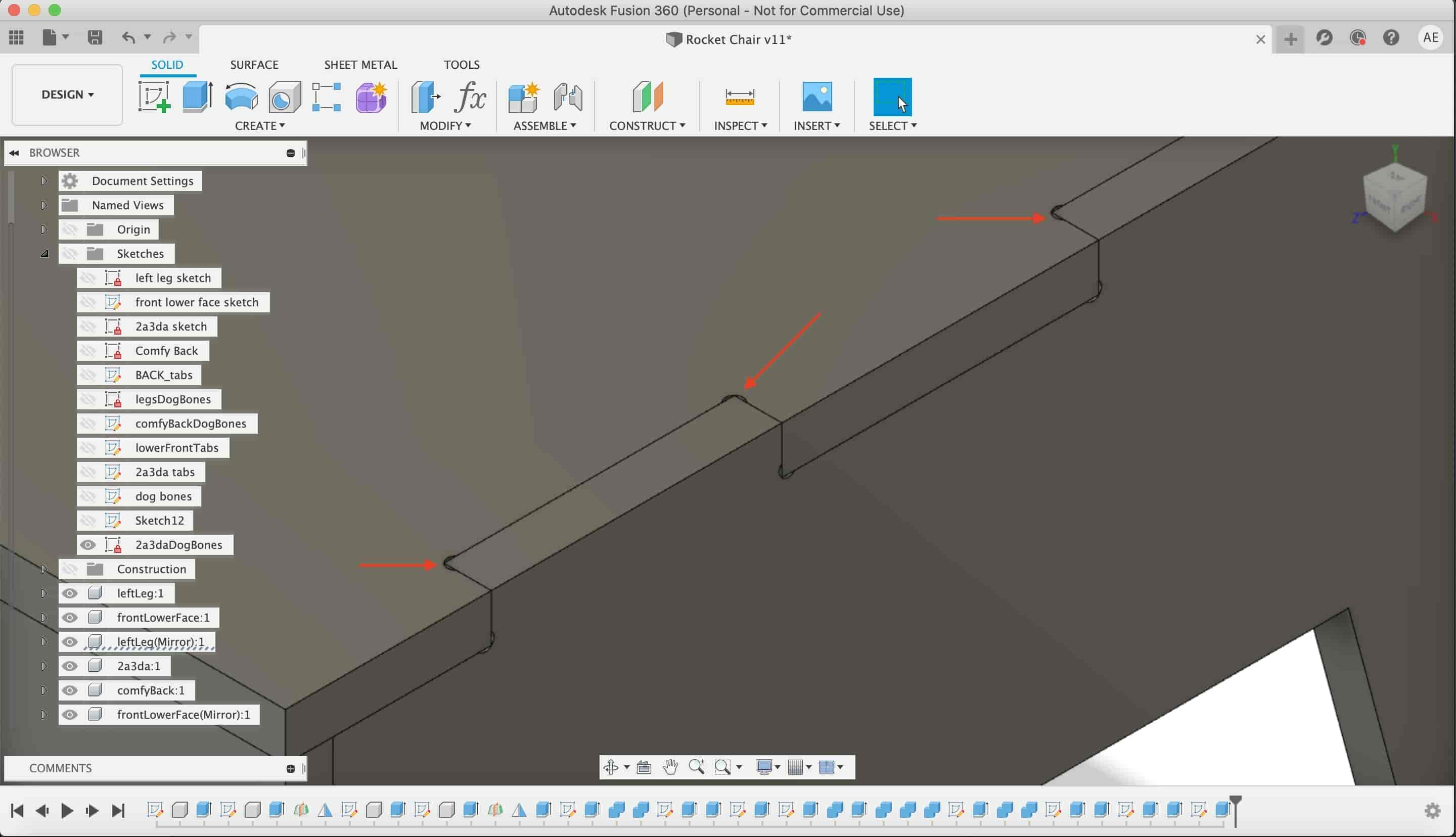
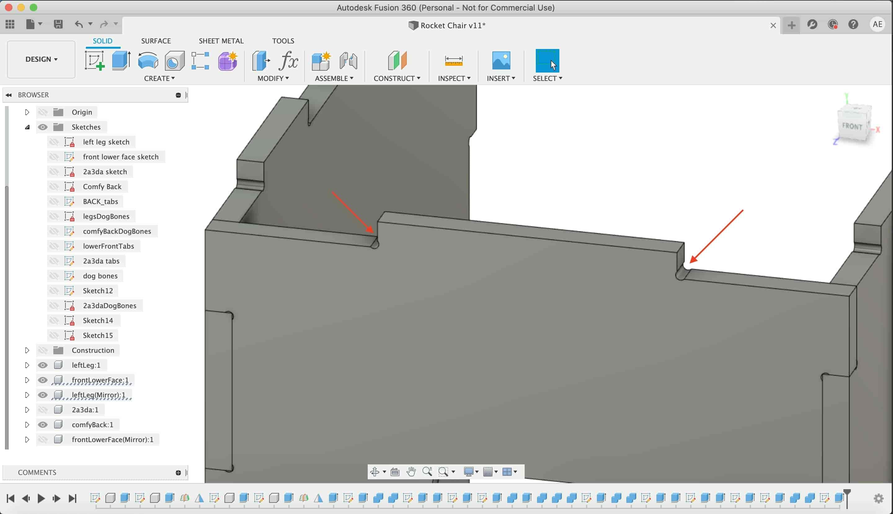
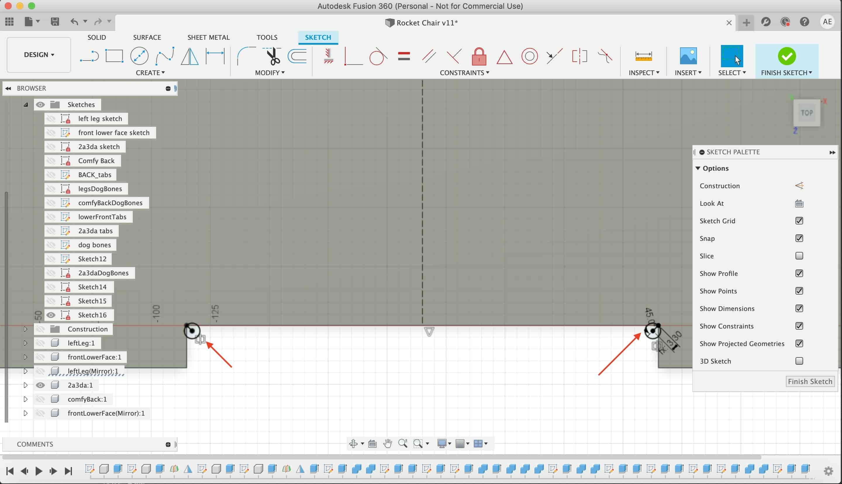
I will use a 6mm end mill to cut the wood.according to the tool diameter I made the dogbone fillets. I made a parametric design. That I can change the end mill diameter and the wood thickness as I want without problems.
I repeated that in the chair back.
Then, I created another hammer fits in the two legs.
I extruded the same fits but I set the start plane from the back of the legs.
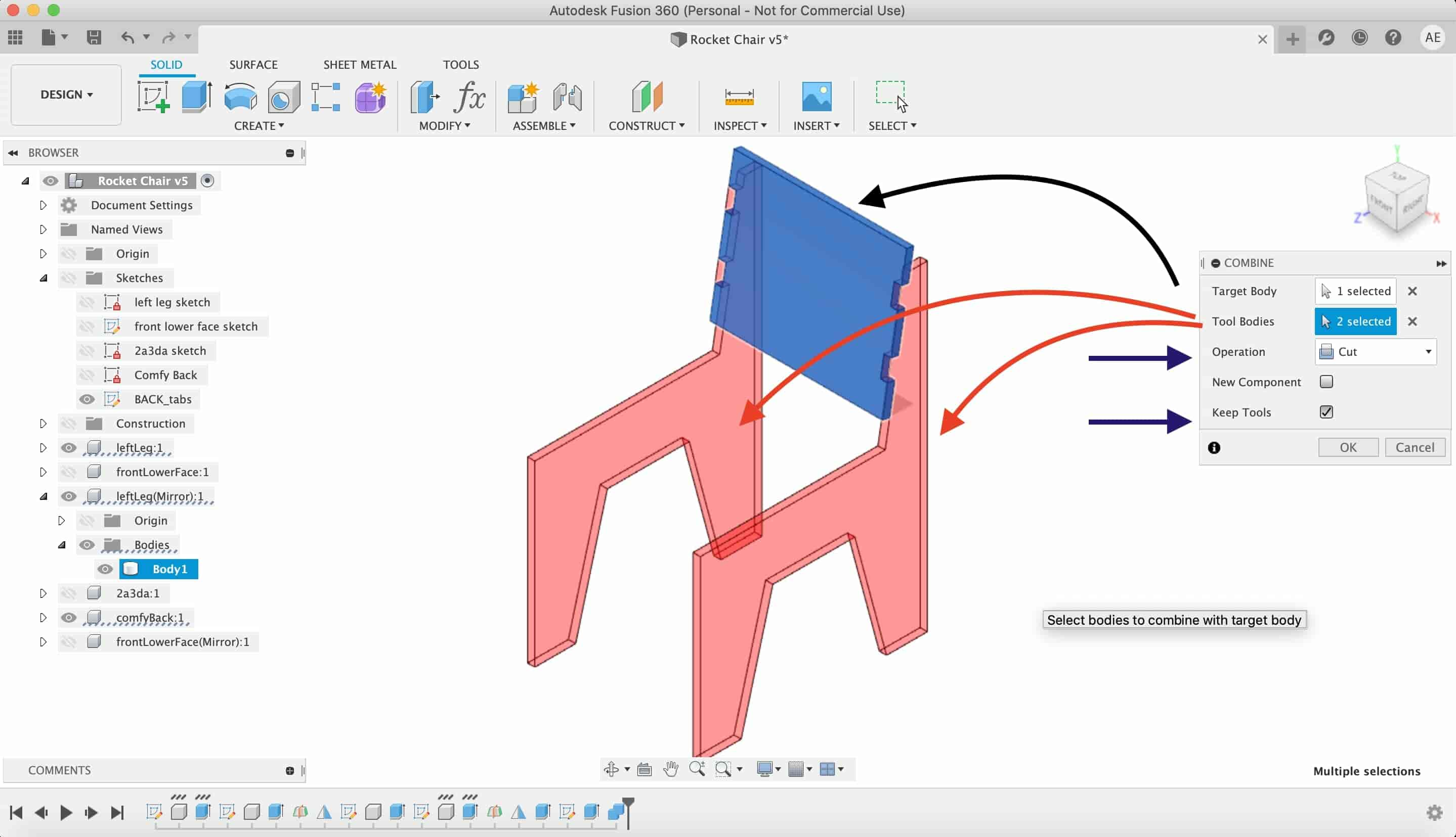
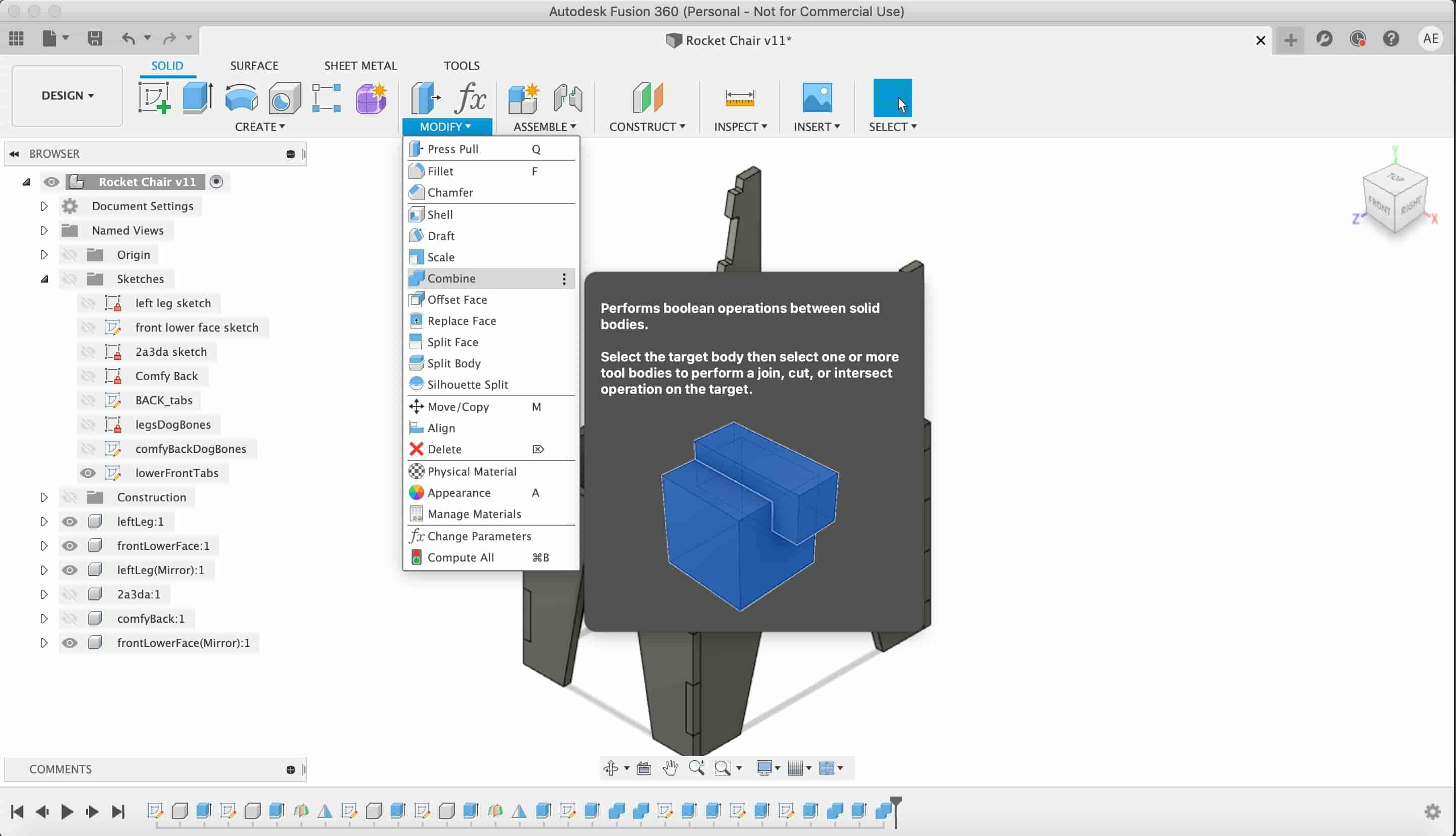
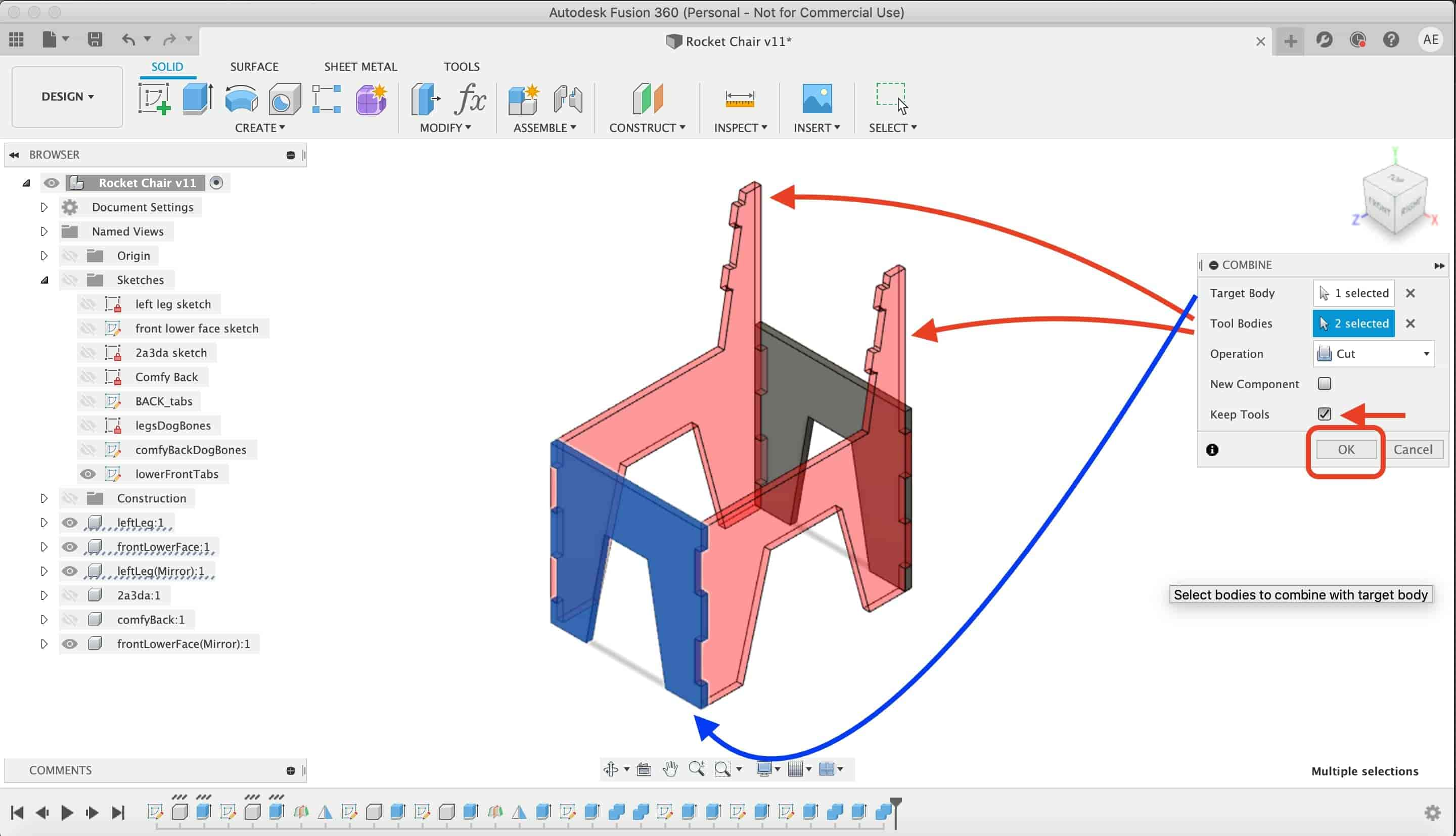
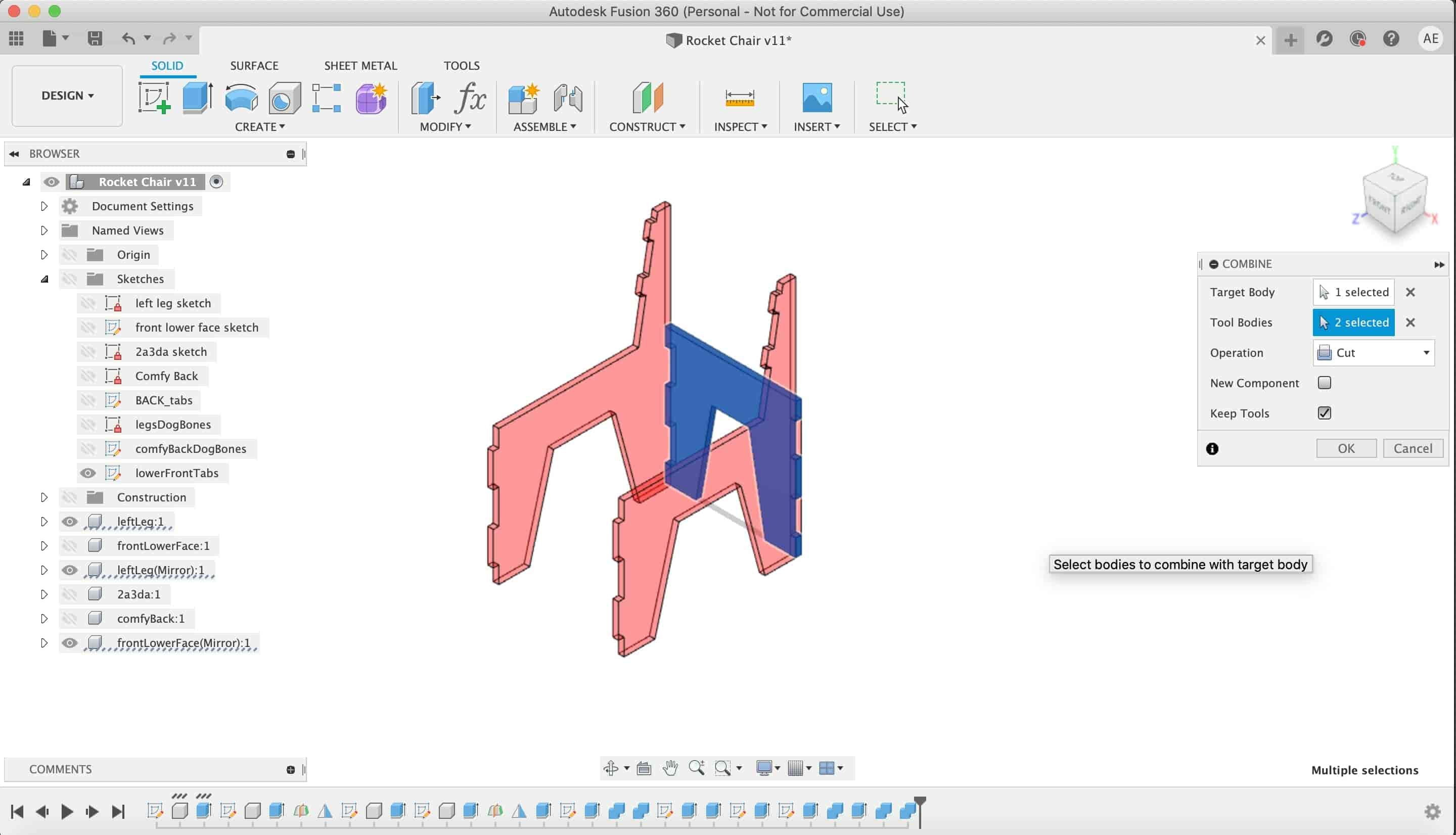
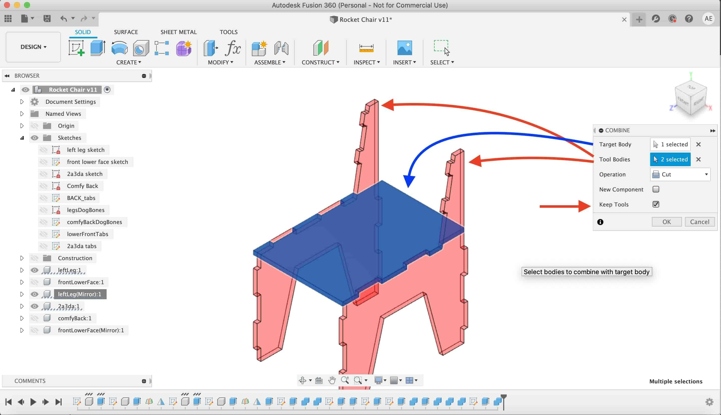
Then, I used the combine tool to make some openings in the lower front and back parts of the chair to fit with the legs hammer fit.
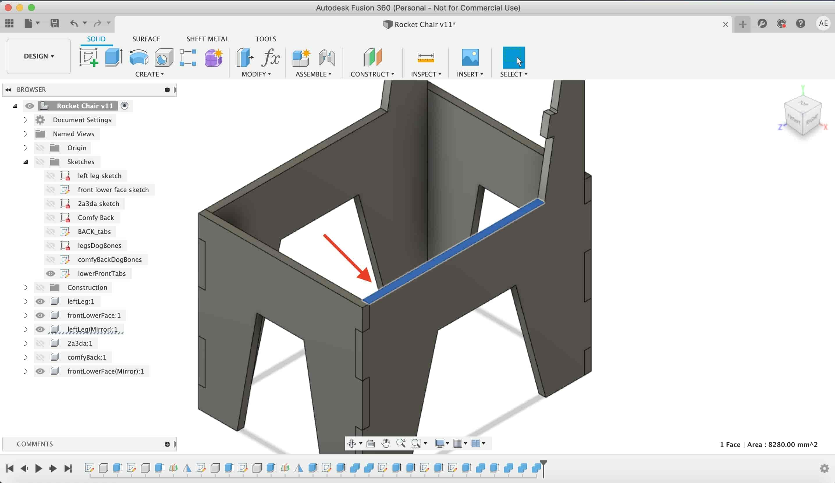
I made another fits to hold the chair legs with the seat.
Then I found that there’s and interfering between the chair seat and it’s legs. I used the combine tool again to solve that problem and get rid off that interference.
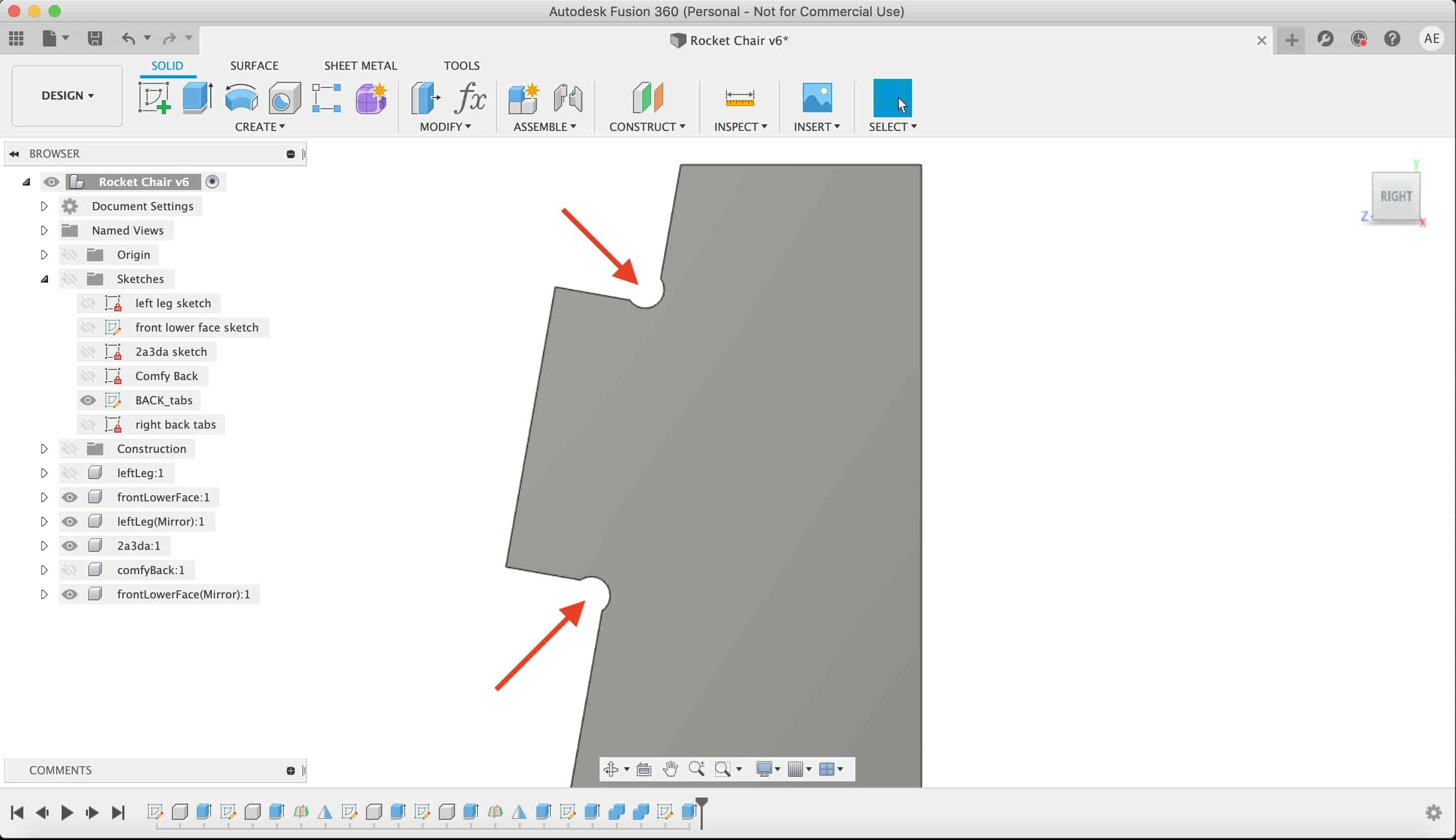
I made some dogbones fillets again in the chair legs.
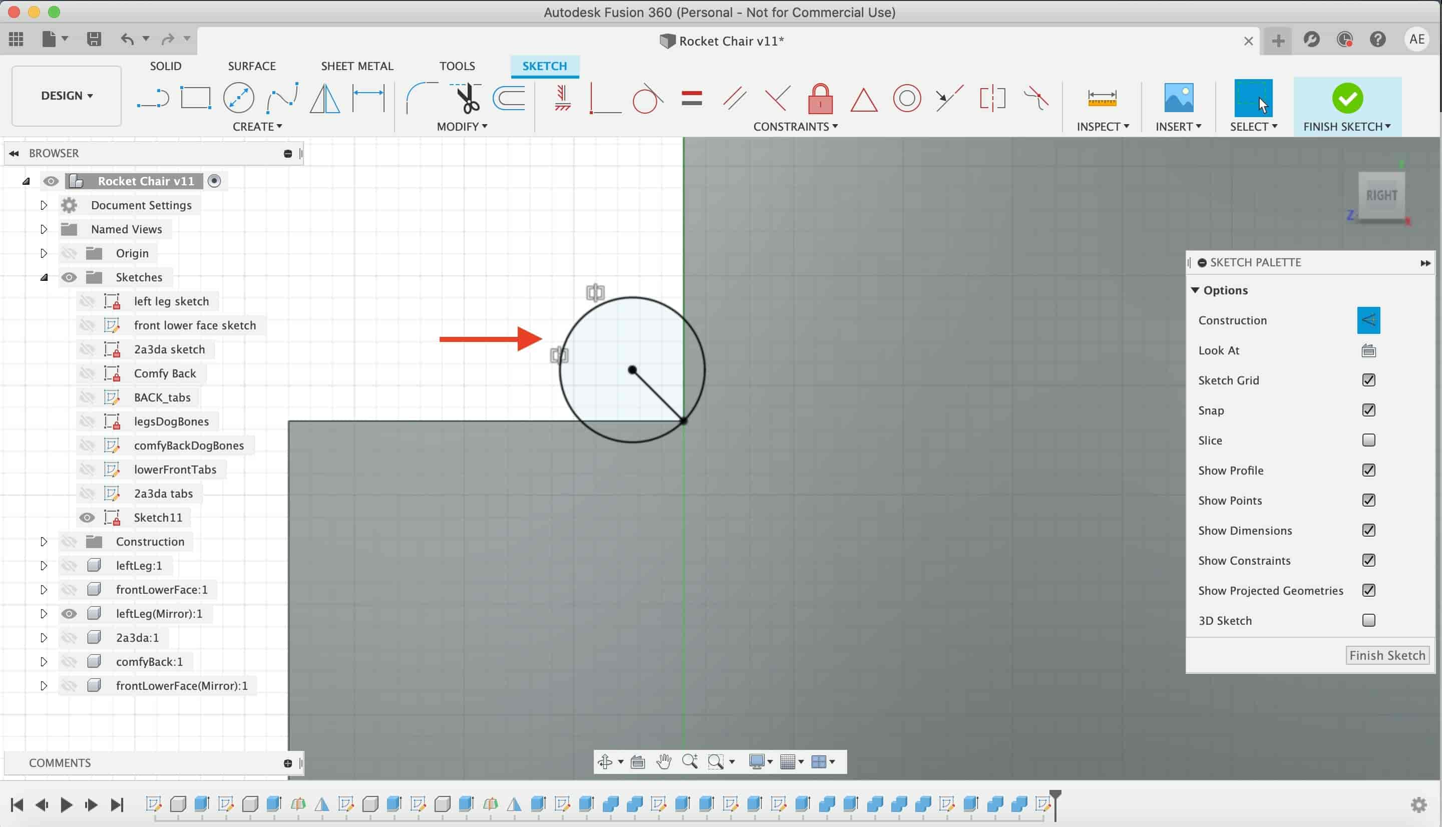
Let’s make some more dogbones in the lower front part.
Again, again, again more dogbone fillets. This time at the chair seat.
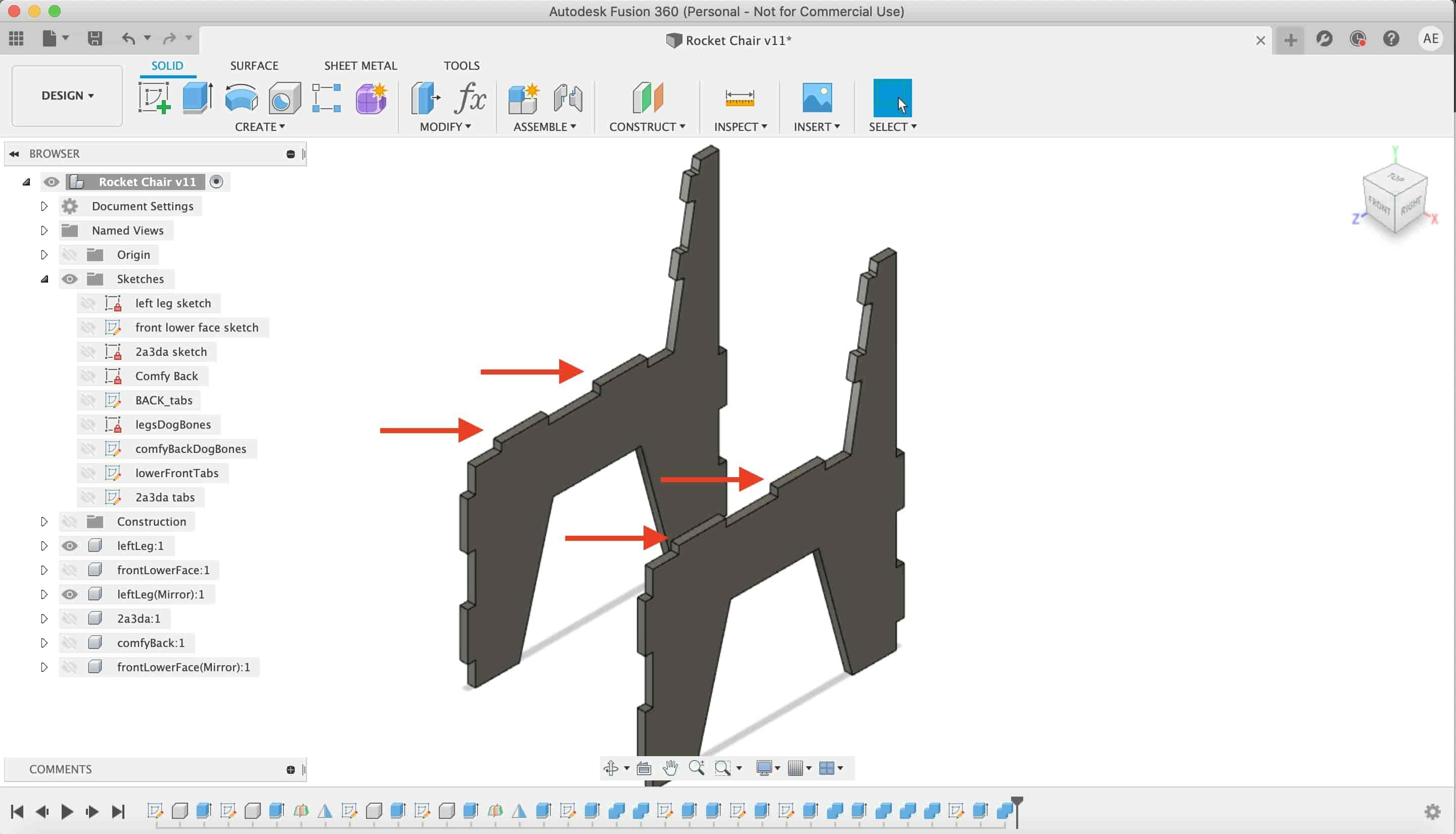
More hammer fits please.
More dogbones please.
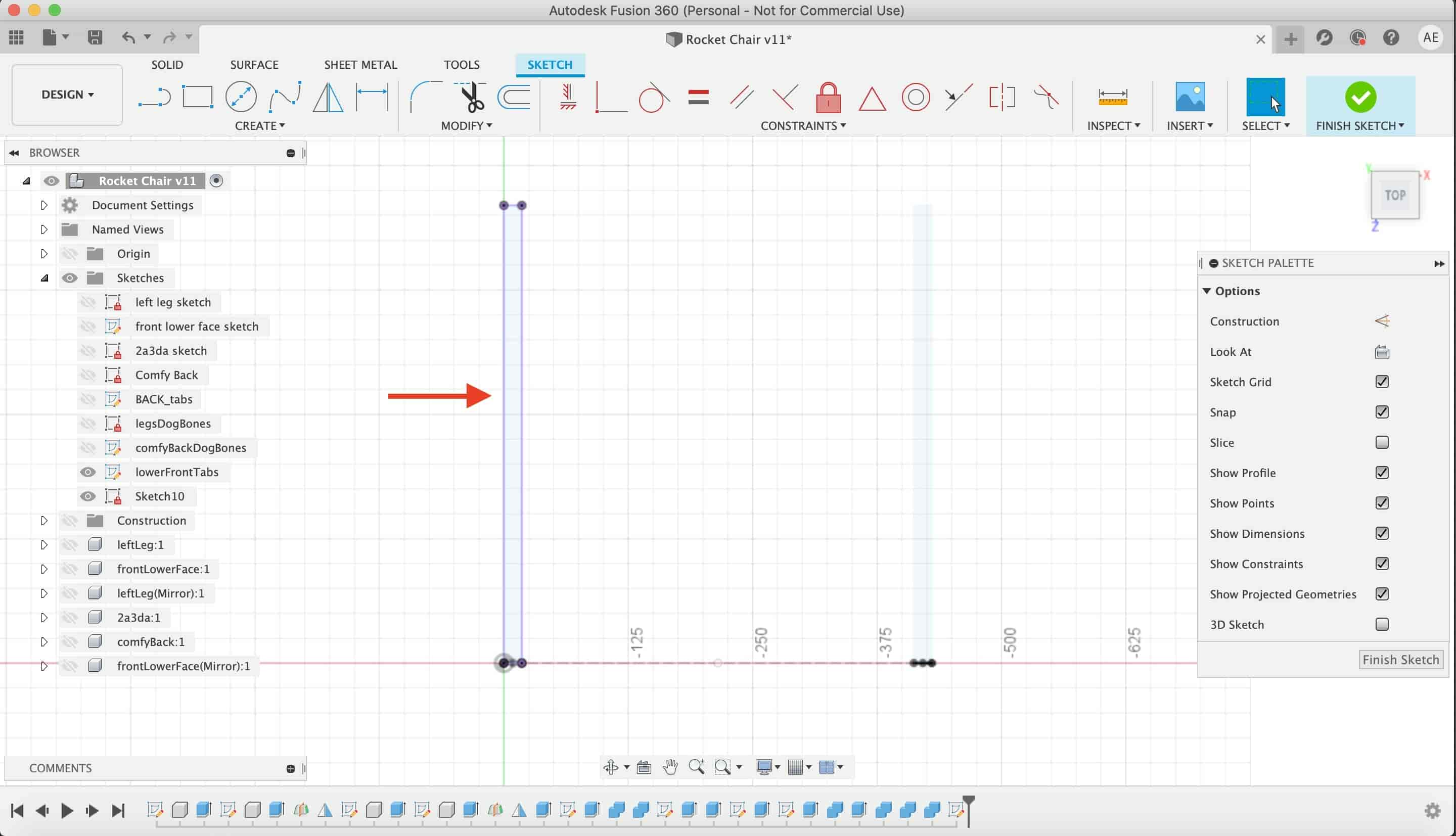
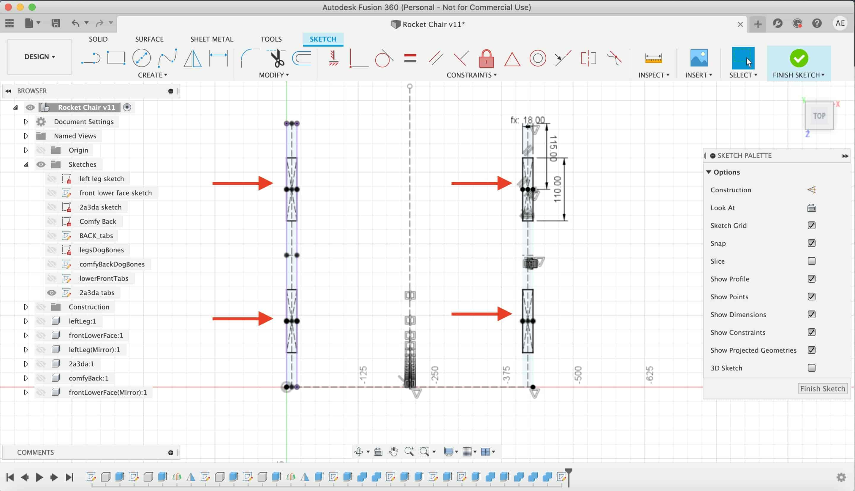
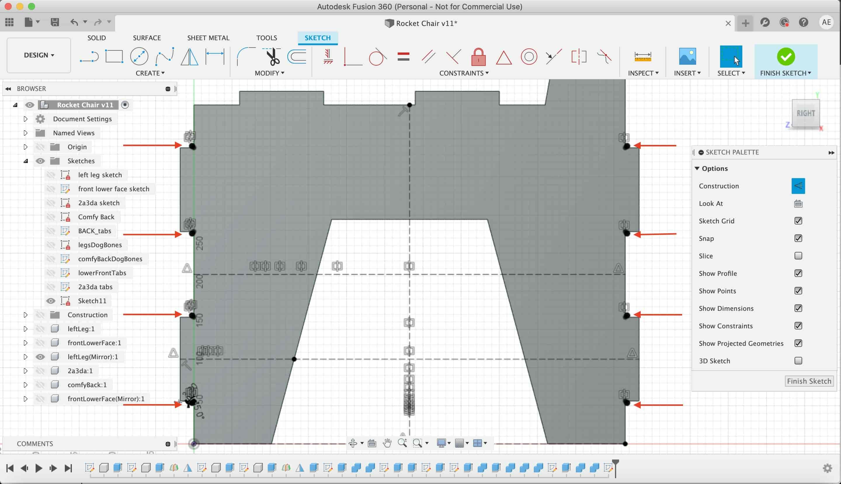
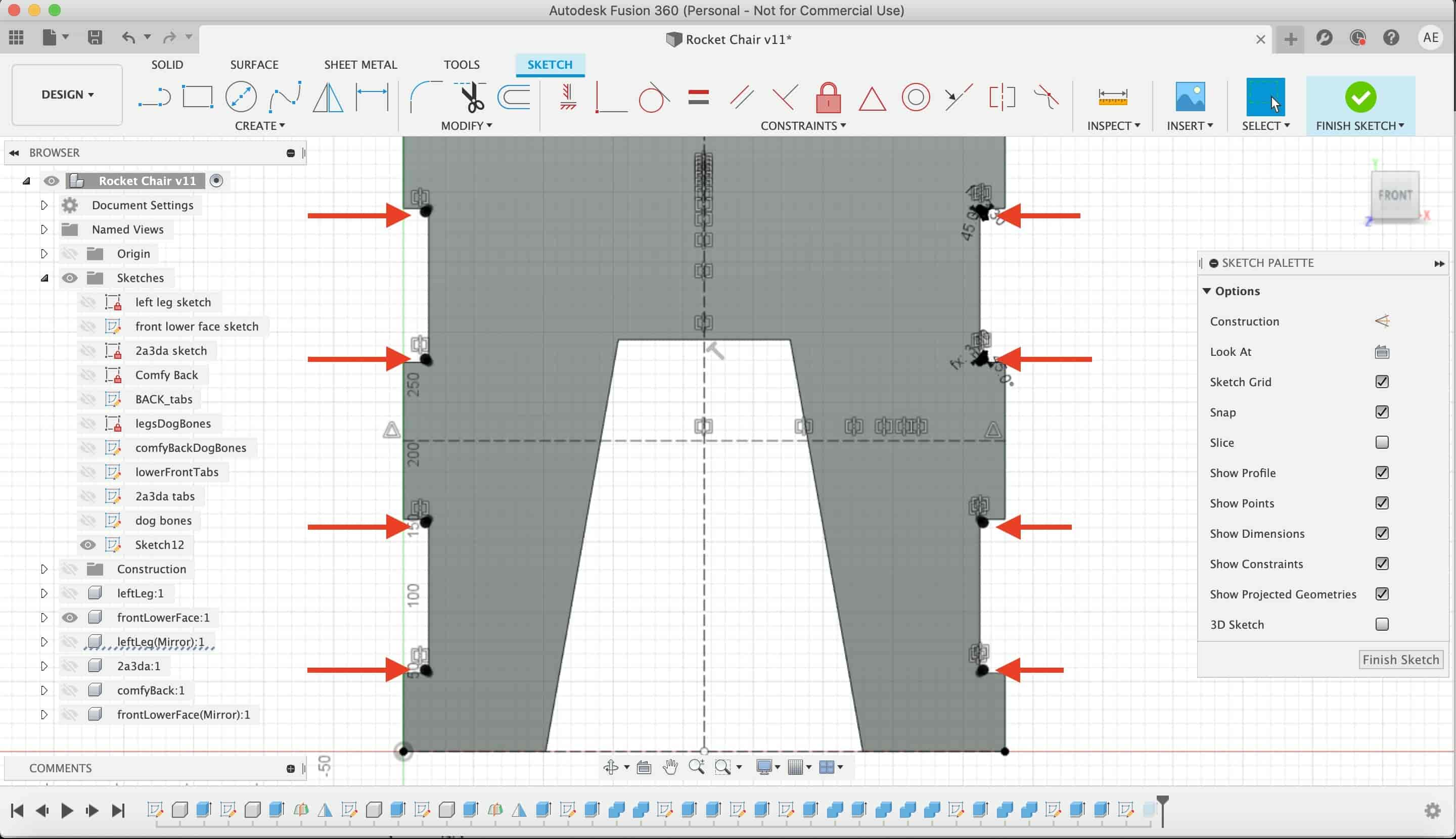
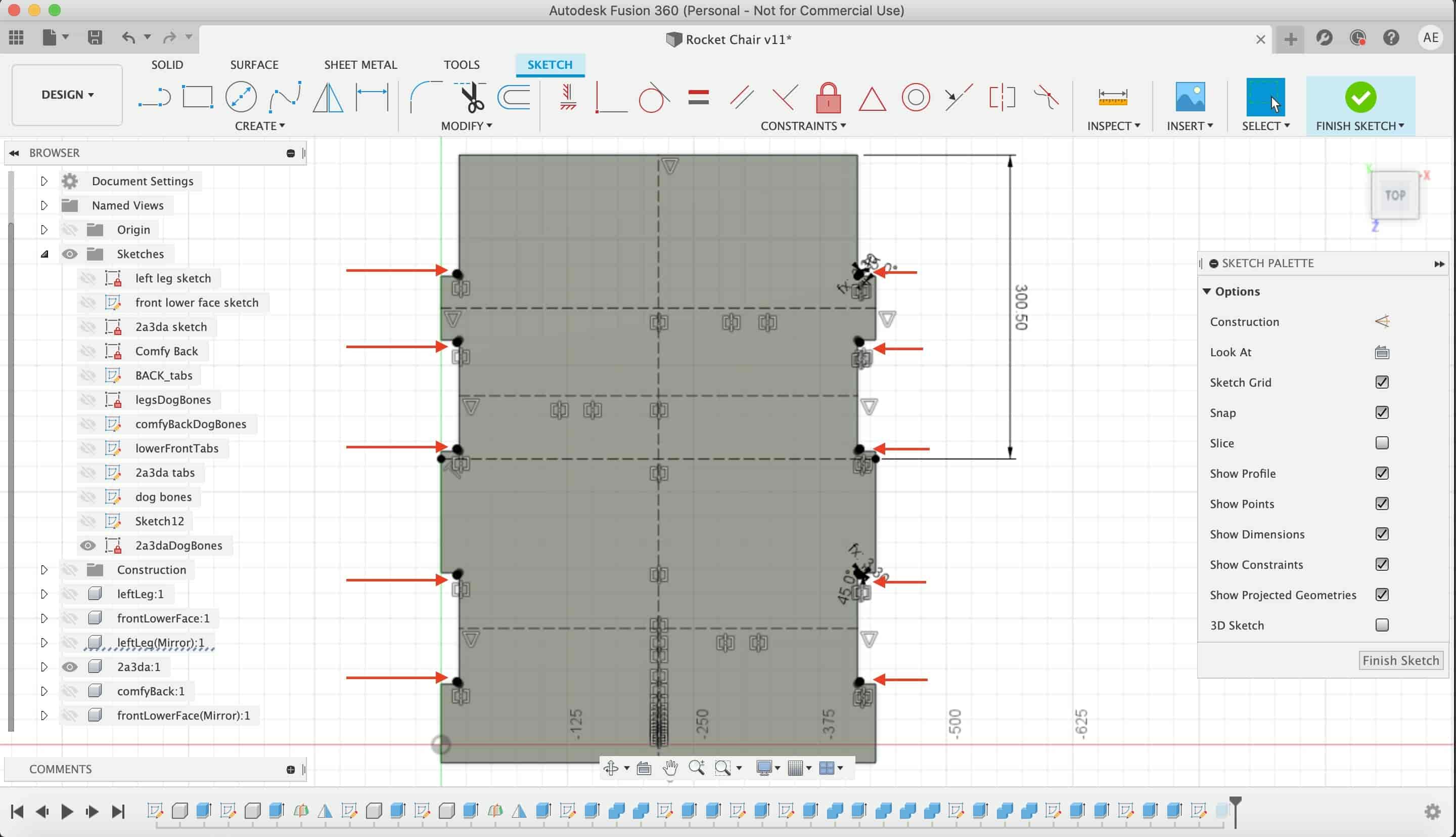
I managed all the chair parts in one sketch to make it easy later on in the fabrication process.
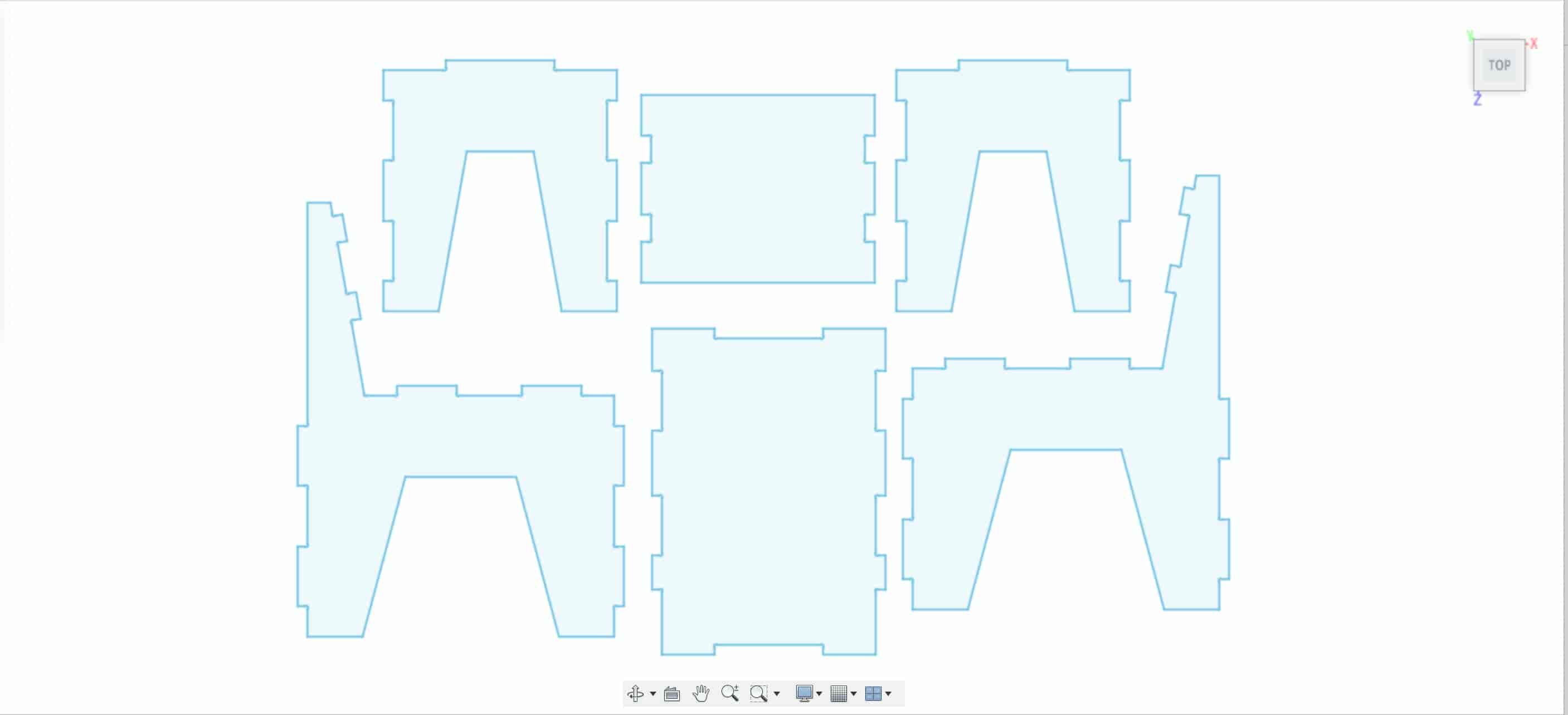
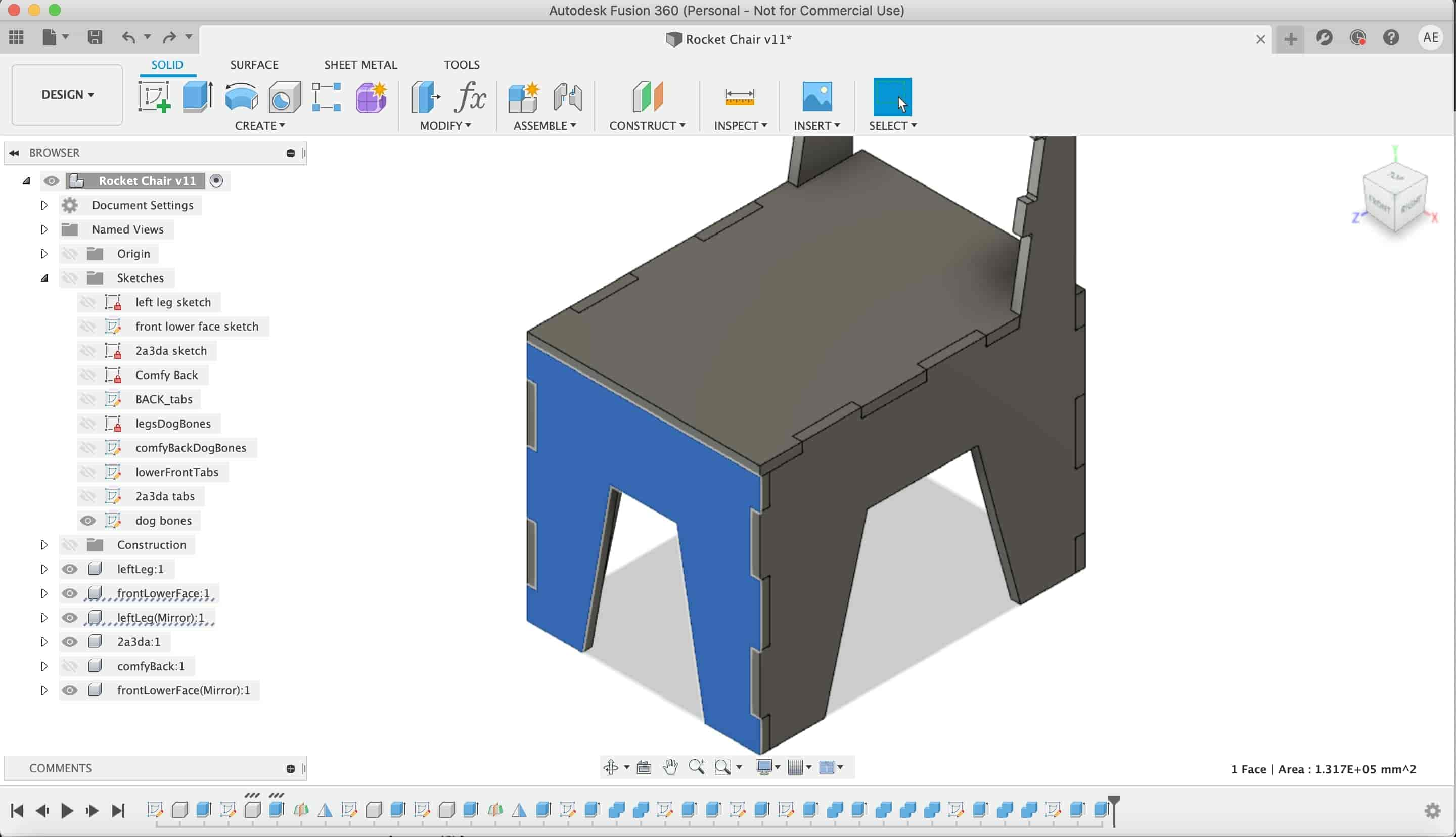
Finally, here’s the final chair after making a lot of hammer fits and a lot of dogbones.
The Dope Chair DXF File Download
- Seat Part DXF.
- Lower back part DXF.
- Back Part DXF.
- Front lower part DXF.
- Left leg Part DXF.
- Right leg part DXF.
- Full chair DXF (6mm Endmill, 18mm stock thickness).
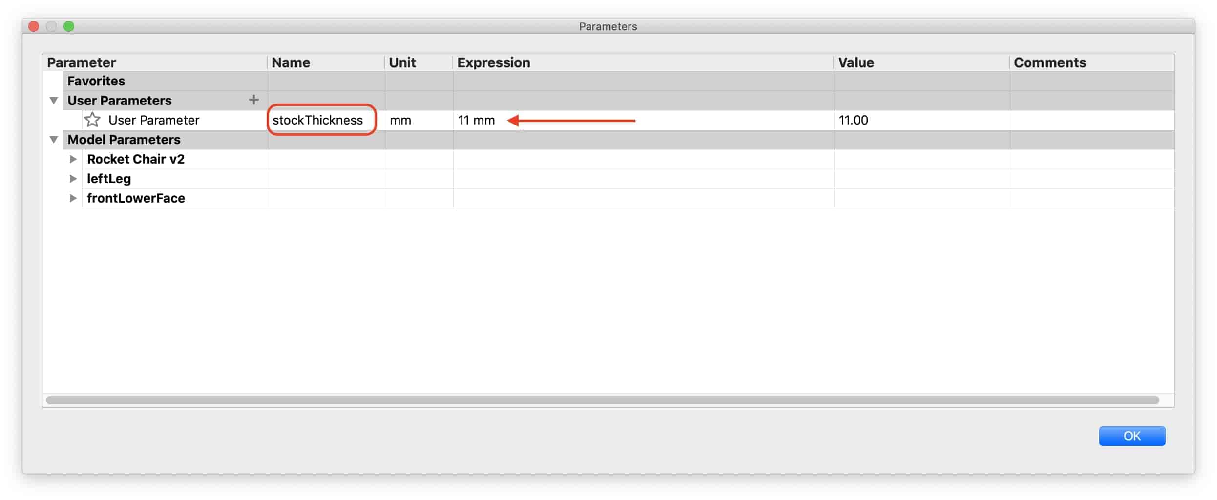
That DXF file contains all the chair parts, its optimized to get machined on a 18mm stock thickness with a 6mm end mill. If you're gonna use a different stock thickness or a different end mill, you can download the fusion360 source files to change/edit the stock thickness and the tool diameter parameters in the design or if you want to edit anything in the design itself feel free to do that.
The Fabrication Process
After exporting the chair DXF file from fusion360, I used a very new CAM software to me with the help of my friend Maichel. Its name is Aspire. I used Aspire to set the CNC router machine cutting parameters like the spindle speed, cut depth, stock thickness, tool diameter, and so on. After setting all of these parameters, we will export a Gcode file that we will send later to the CNC router machine to cut the chair parts.
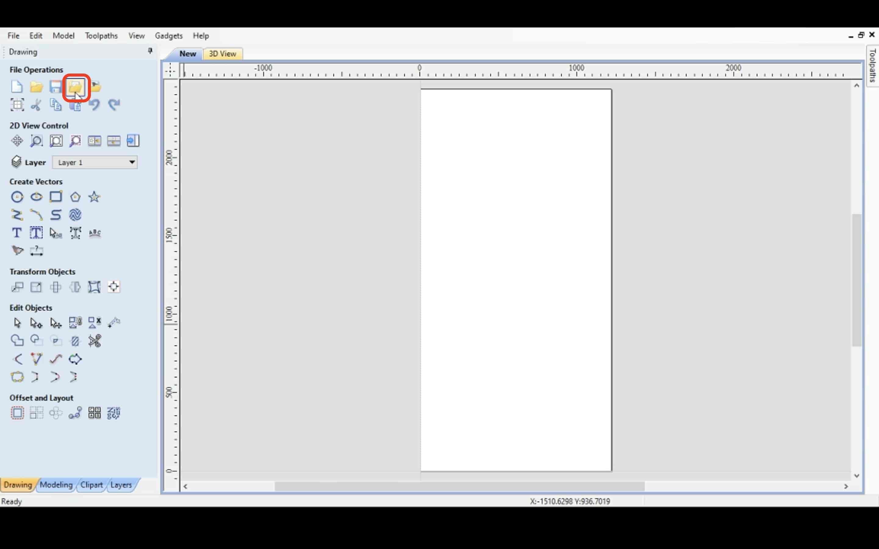
First thing we need to do in Aspire, is to import our DXF file into Aspire.
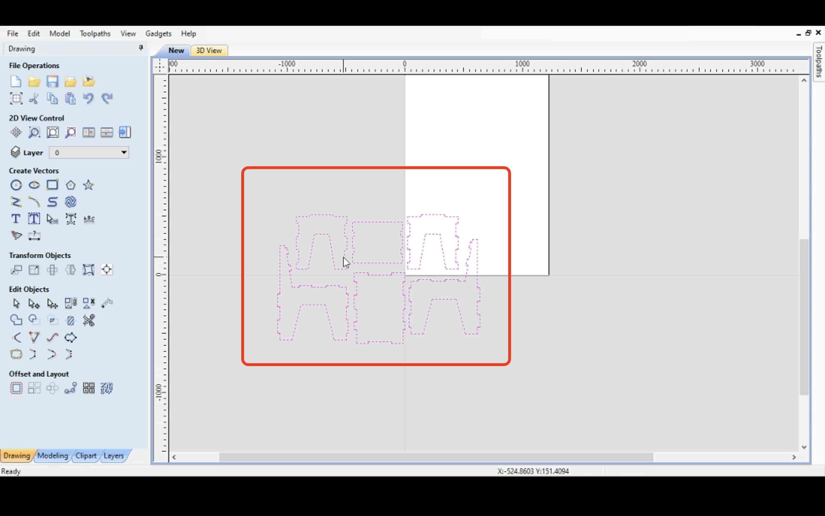
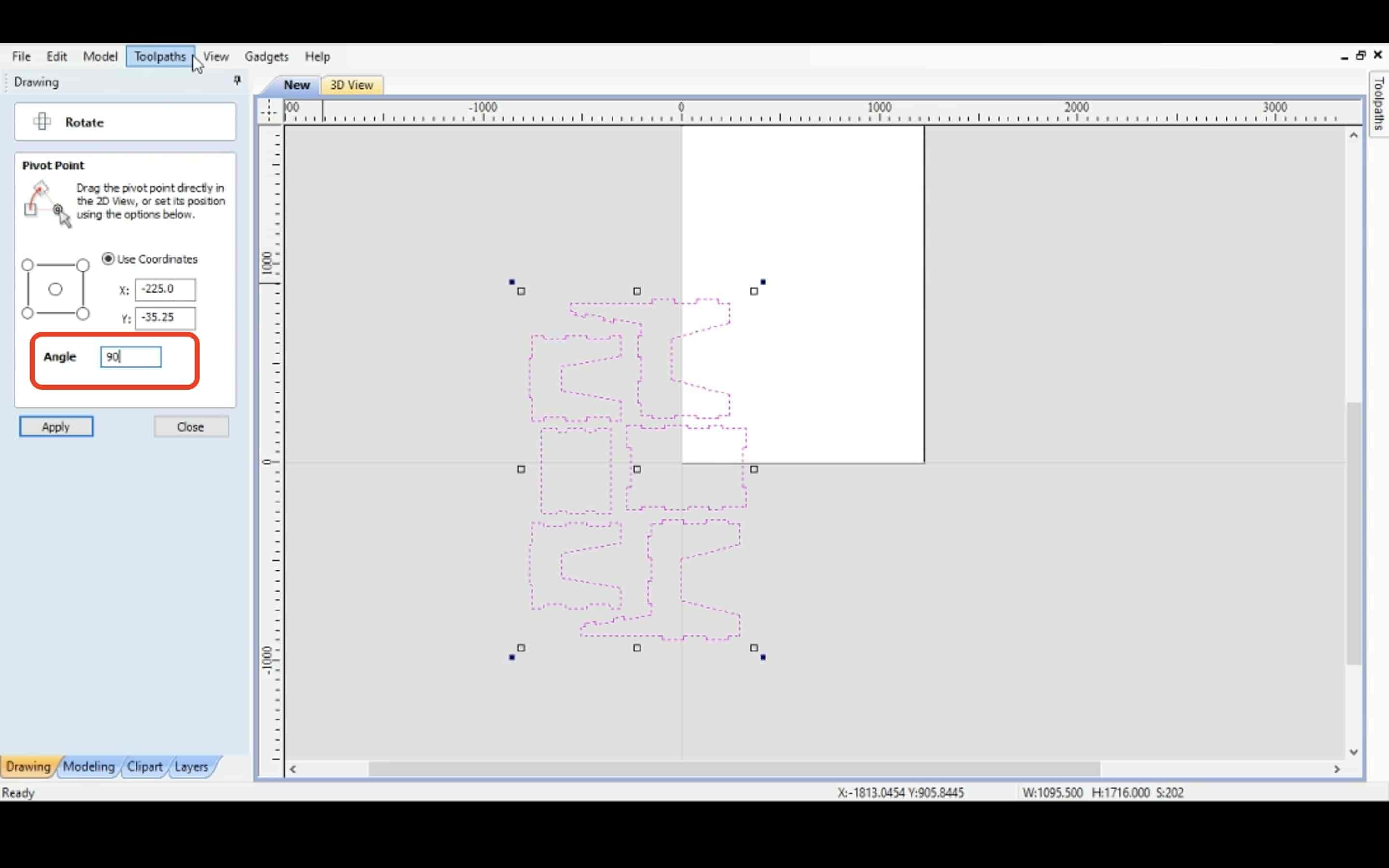
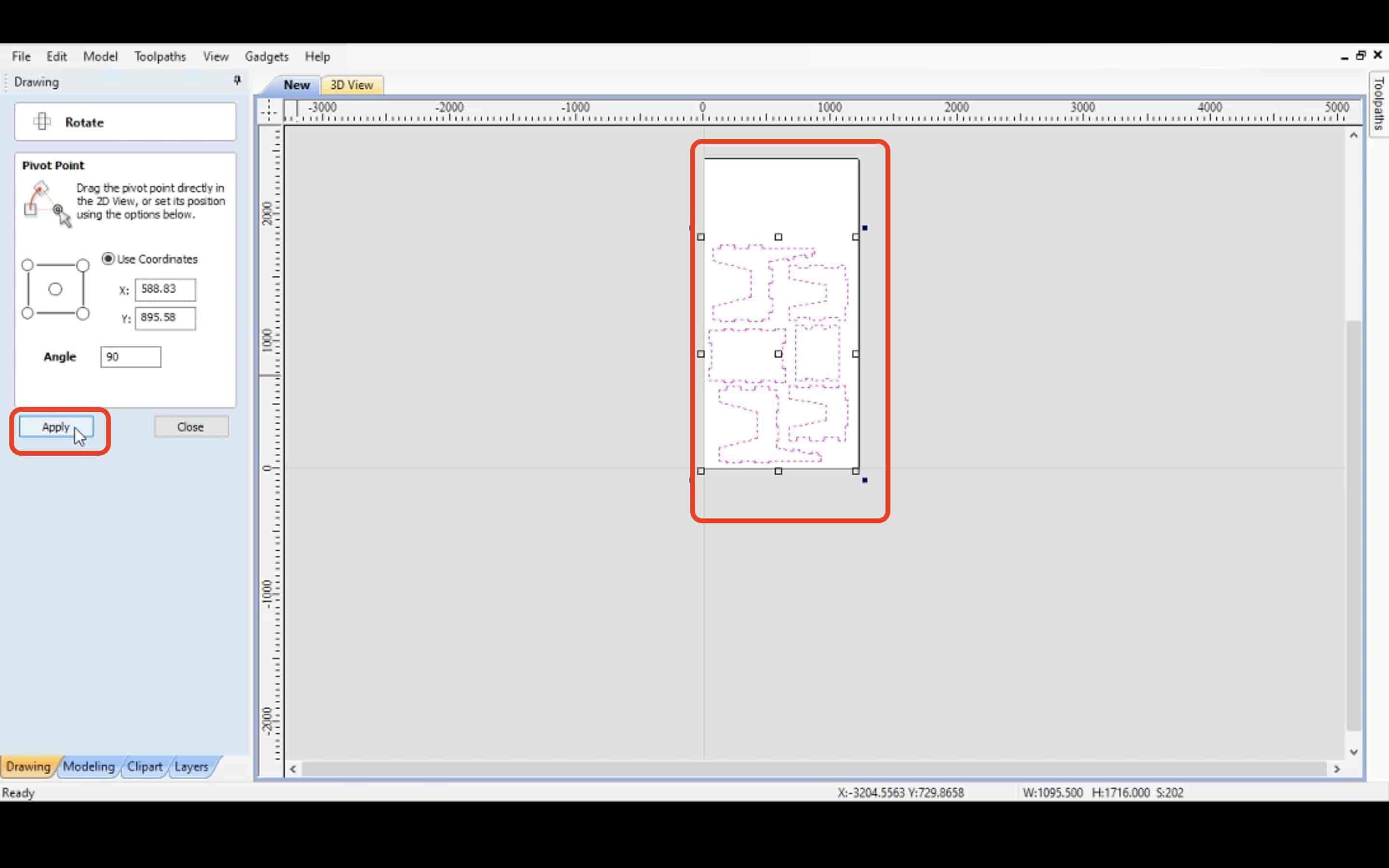
Then, from the rotate tool we rotated the DXF file 90 degrees and moved it to make it inside our workspace area.
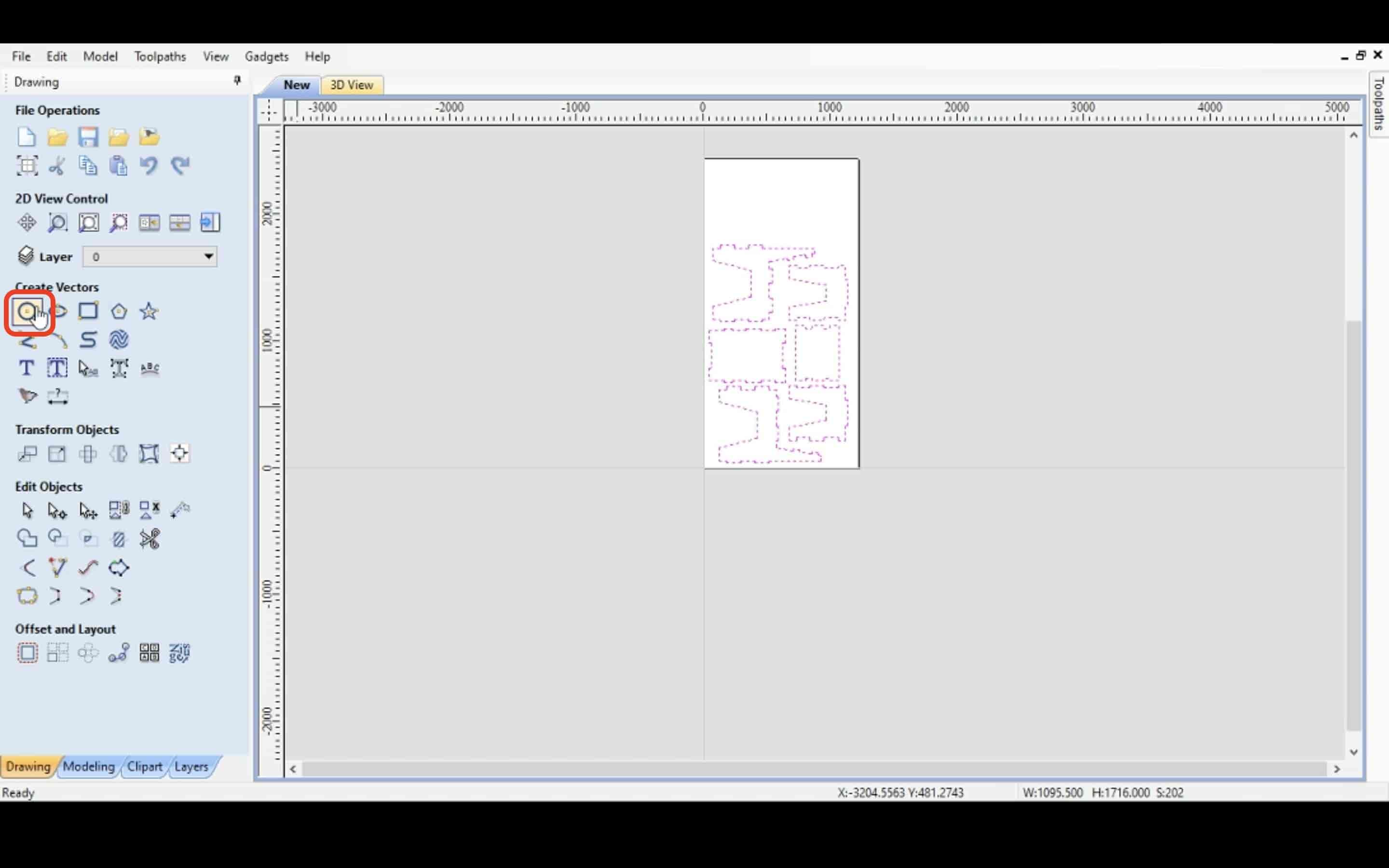
After that, make some holes in the wood sheet that we will use later as a guide/reference to secure it on the machine bed with some screws.
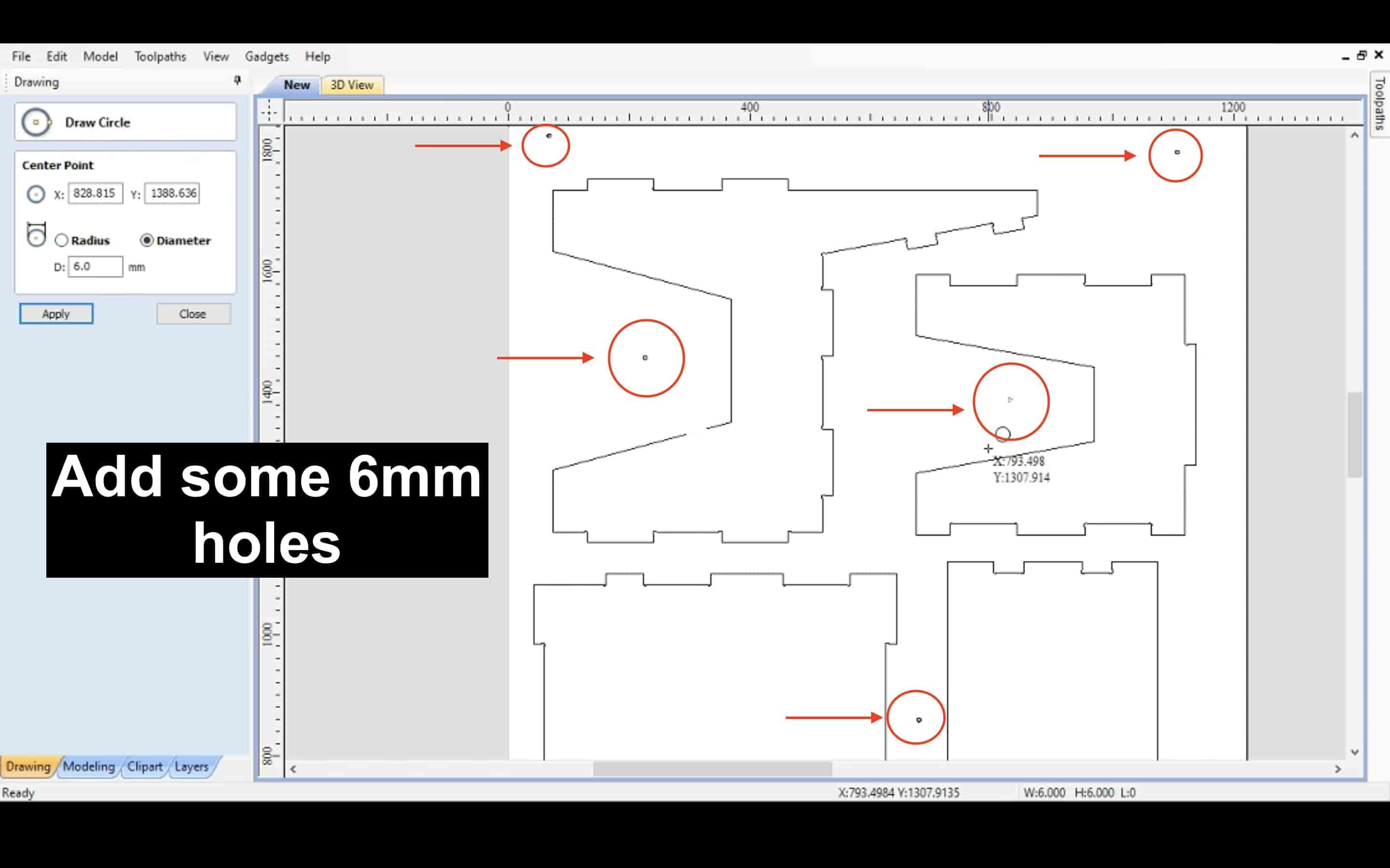
Then I selected all the holes that I made and from the drilling toolpath tool I set the cut depth to 5mm and the endmill that I will use drill the wooden sheet to 6mm. Then, I clicked calculate to generate the tootlpath for this job
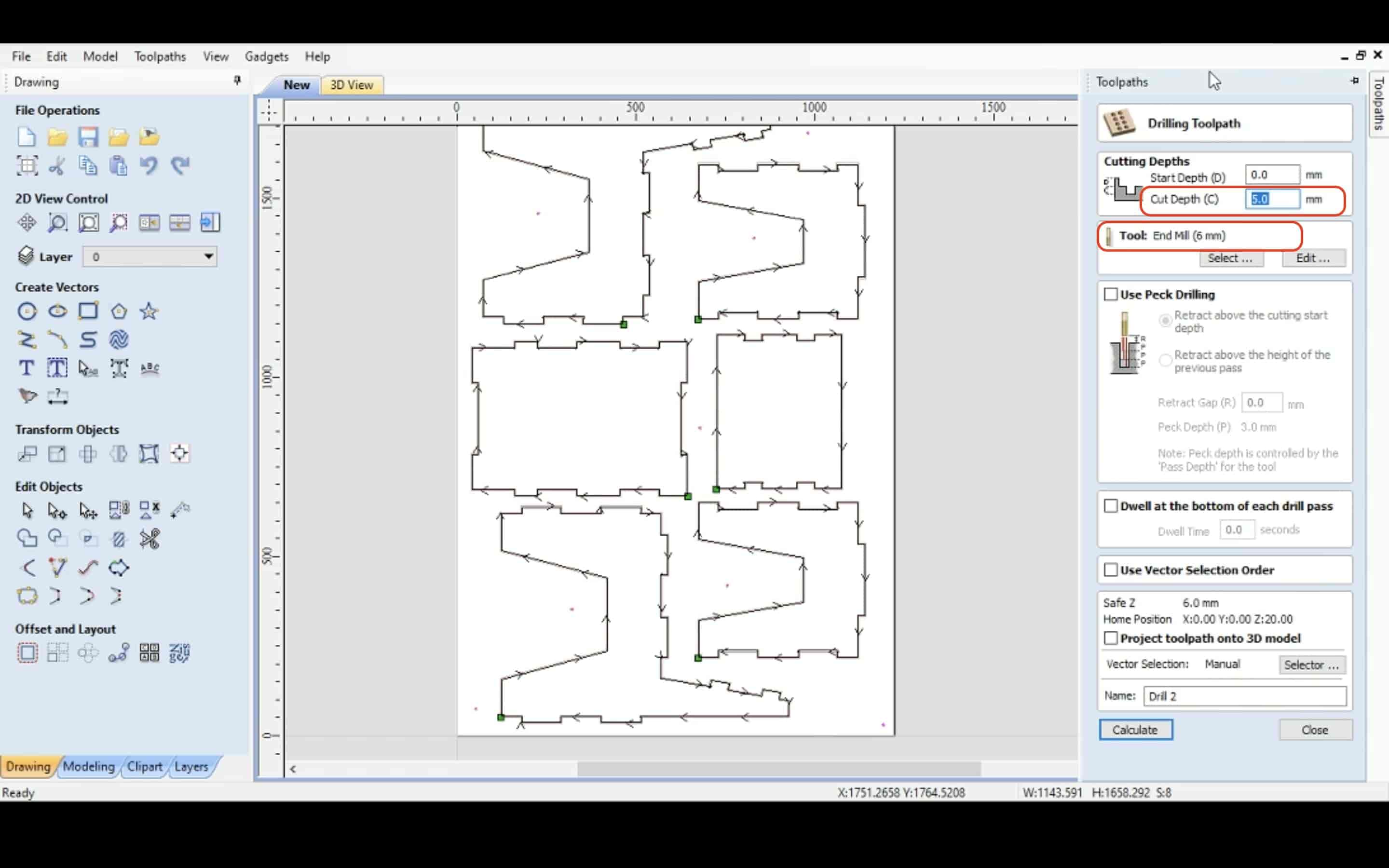
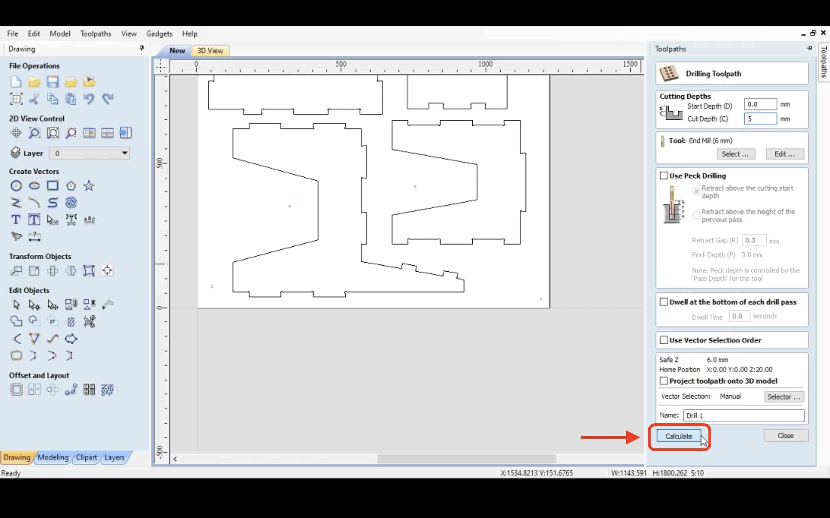
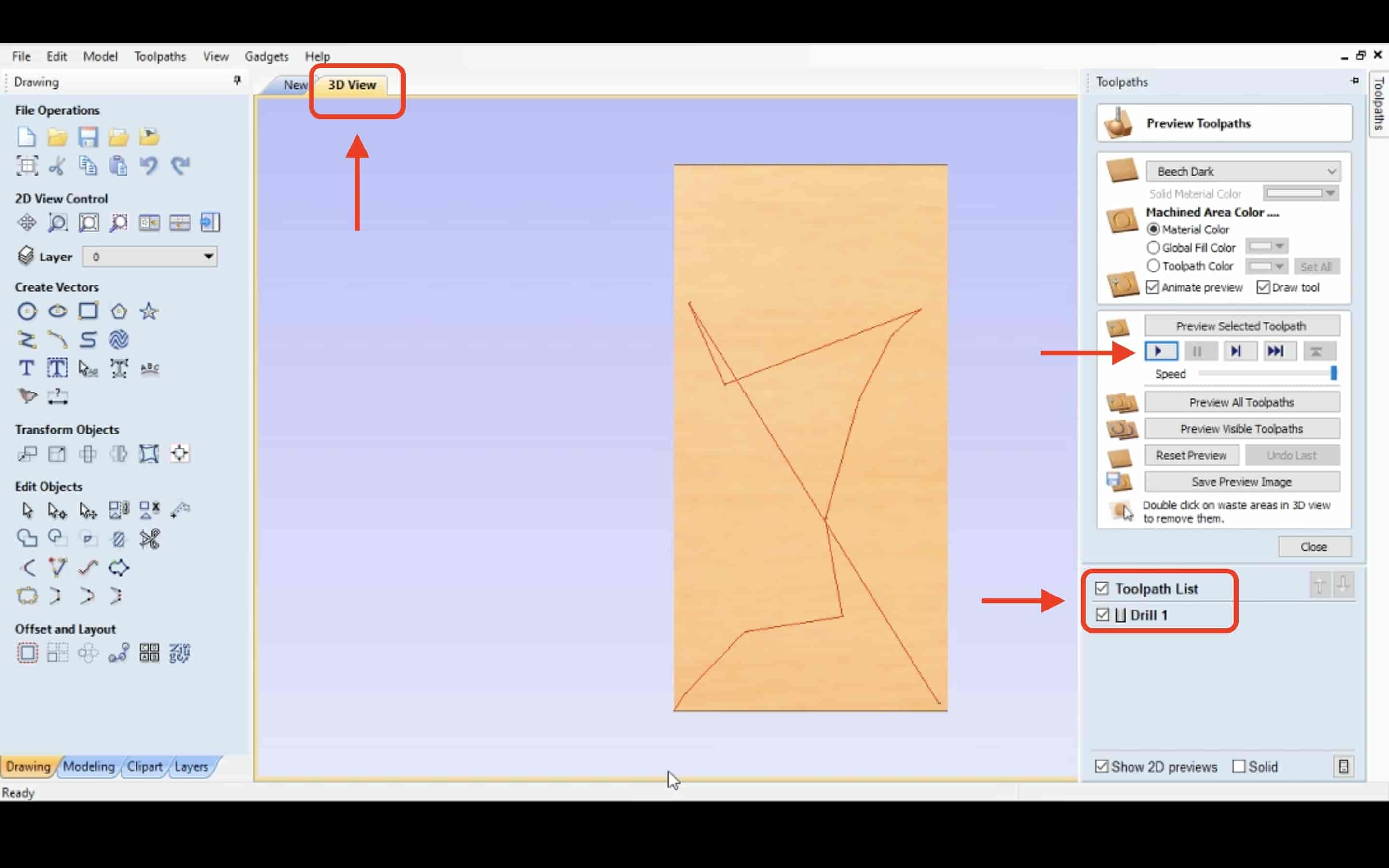
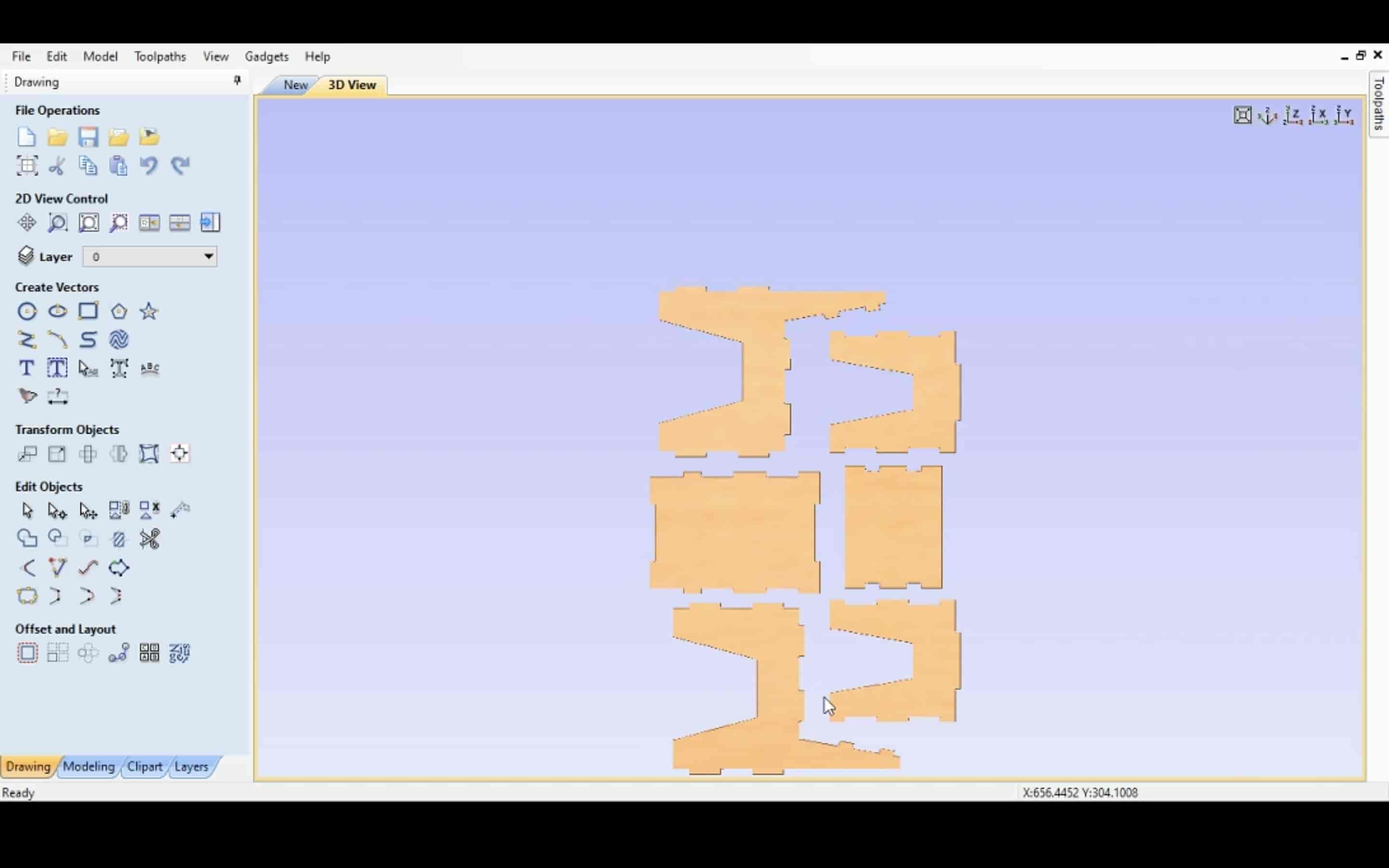
Once you click calculate, it will open the 3D view of that toolpath.
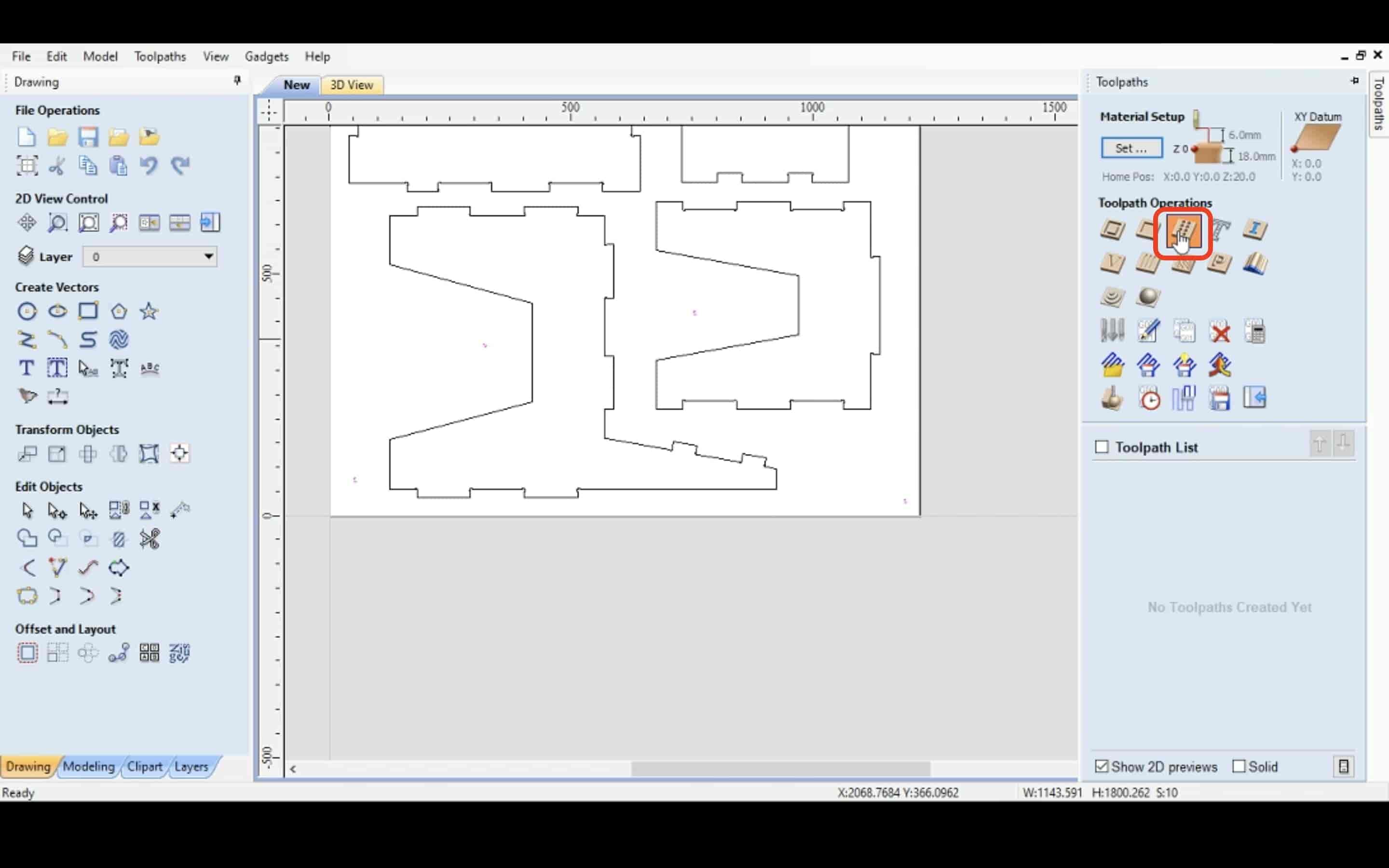
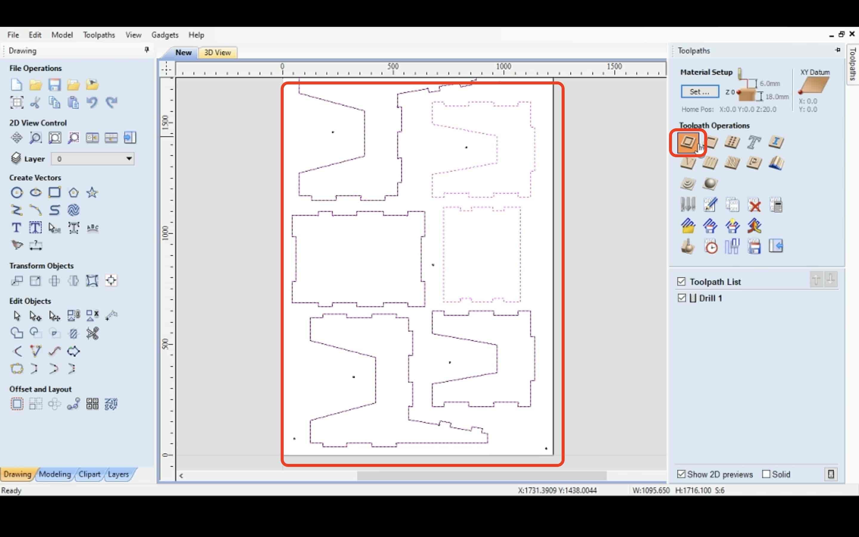
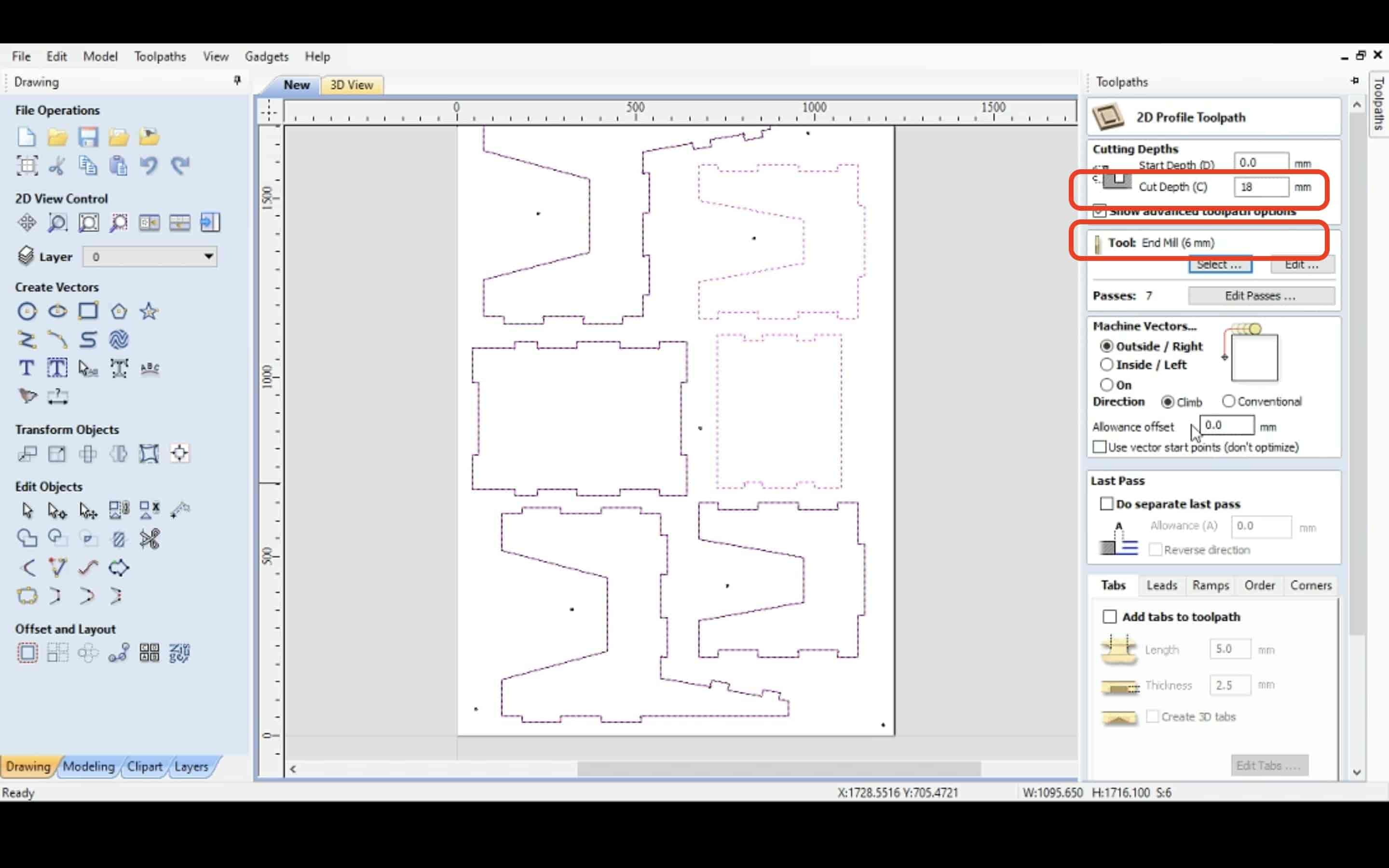
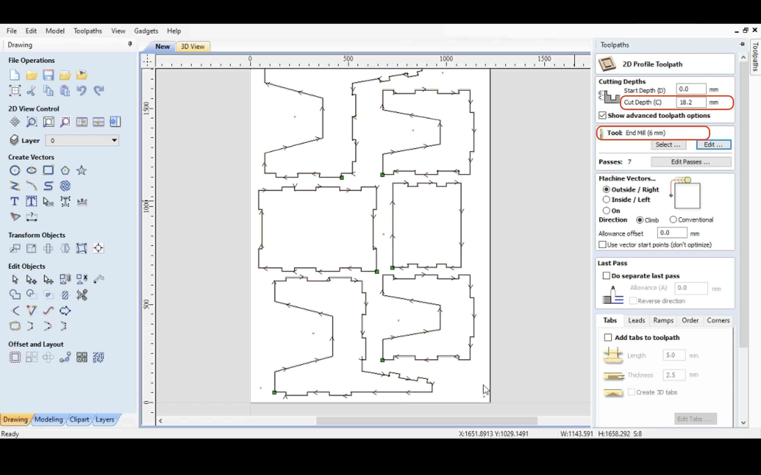
After creating the drills toolpath successfully, let’s create the cut toolpath. Select all your parts vector lines and choose the 3D profile toolpath tool, here we need to se the cutting parameters that the machine will follow you cut the parts. I set the cut depth to 18mm according to the wood sheet stock thickness, and the endmill diameter to 6mm. Then, I clicked calculate.
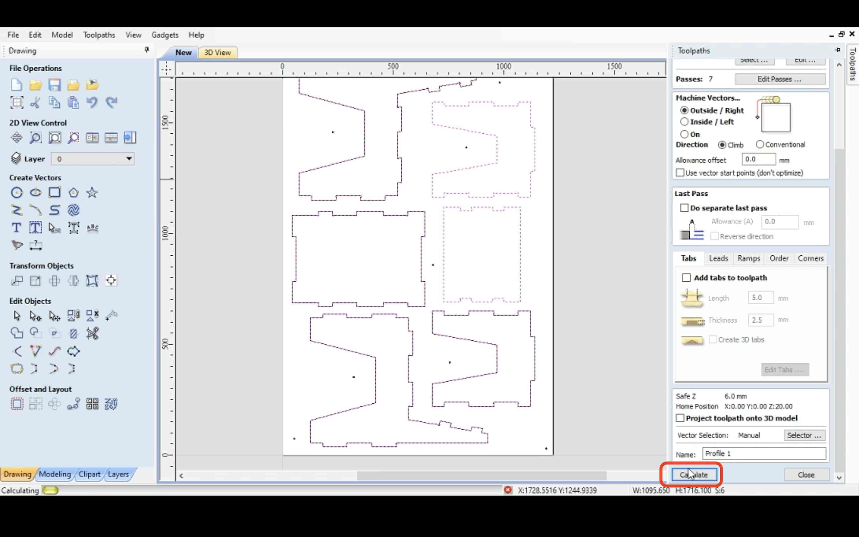
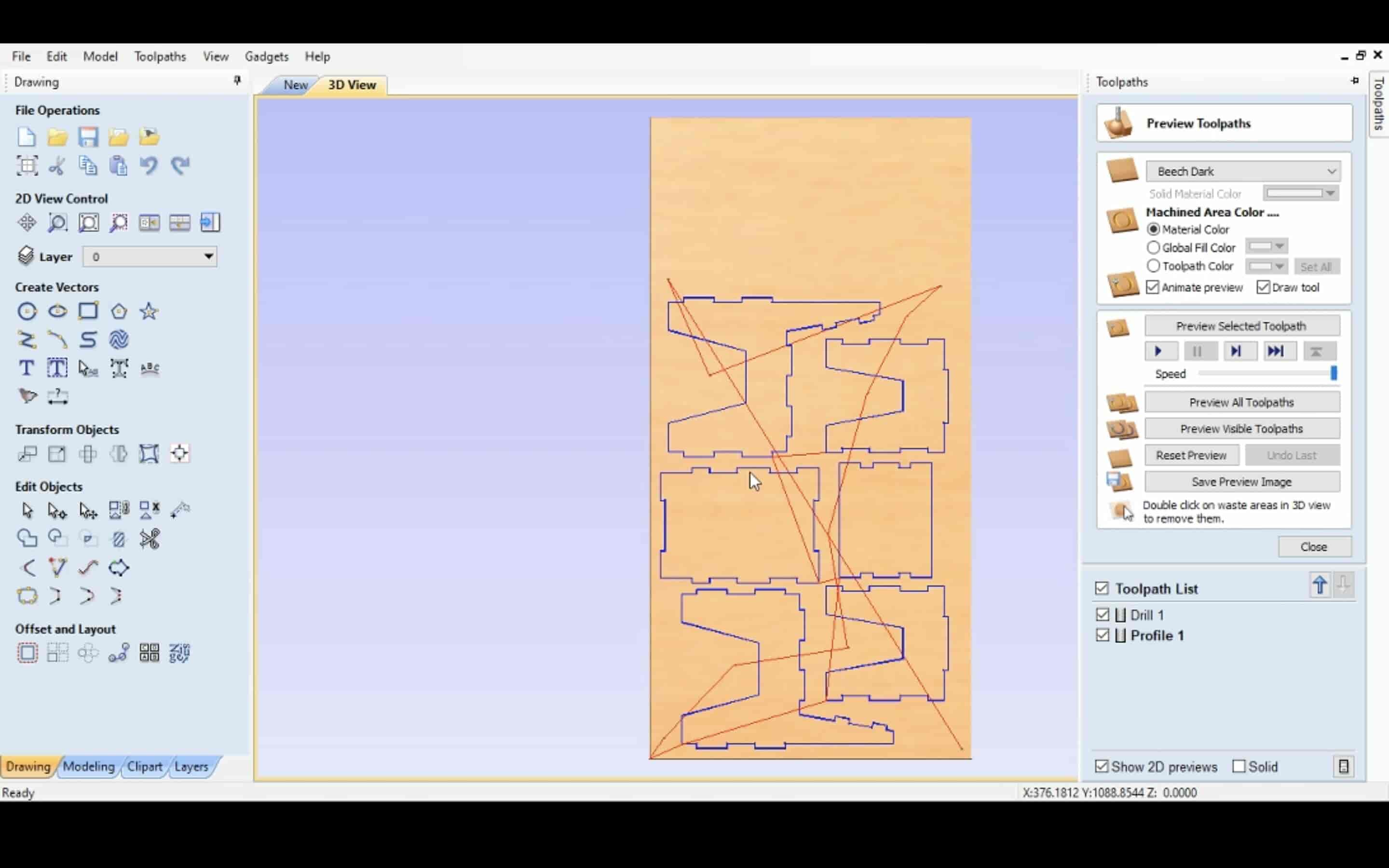
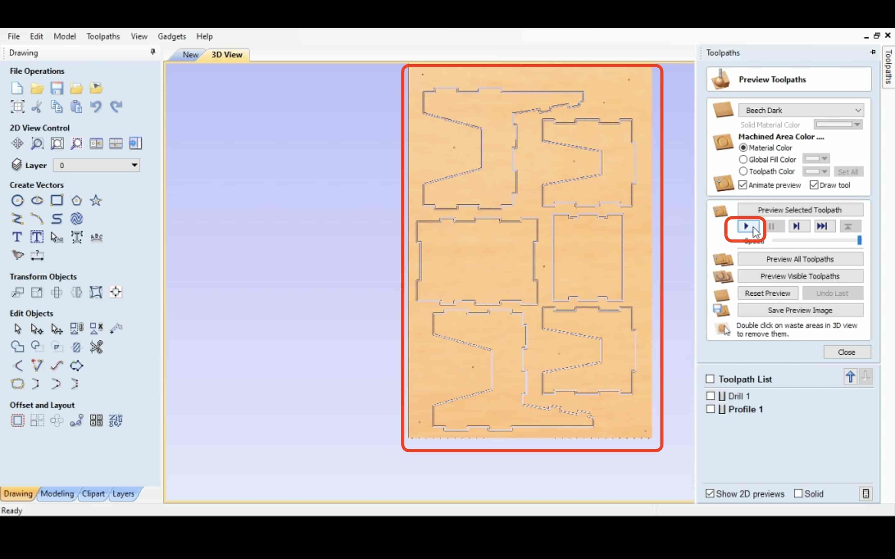
Once you pressed the calculate button it will open the 3D view for your job. Click on the play button. As you can see the cutting process it didn’t go all the way through the wood stock, So I edited the cut depth to 18.2mm instead of 18.0mm
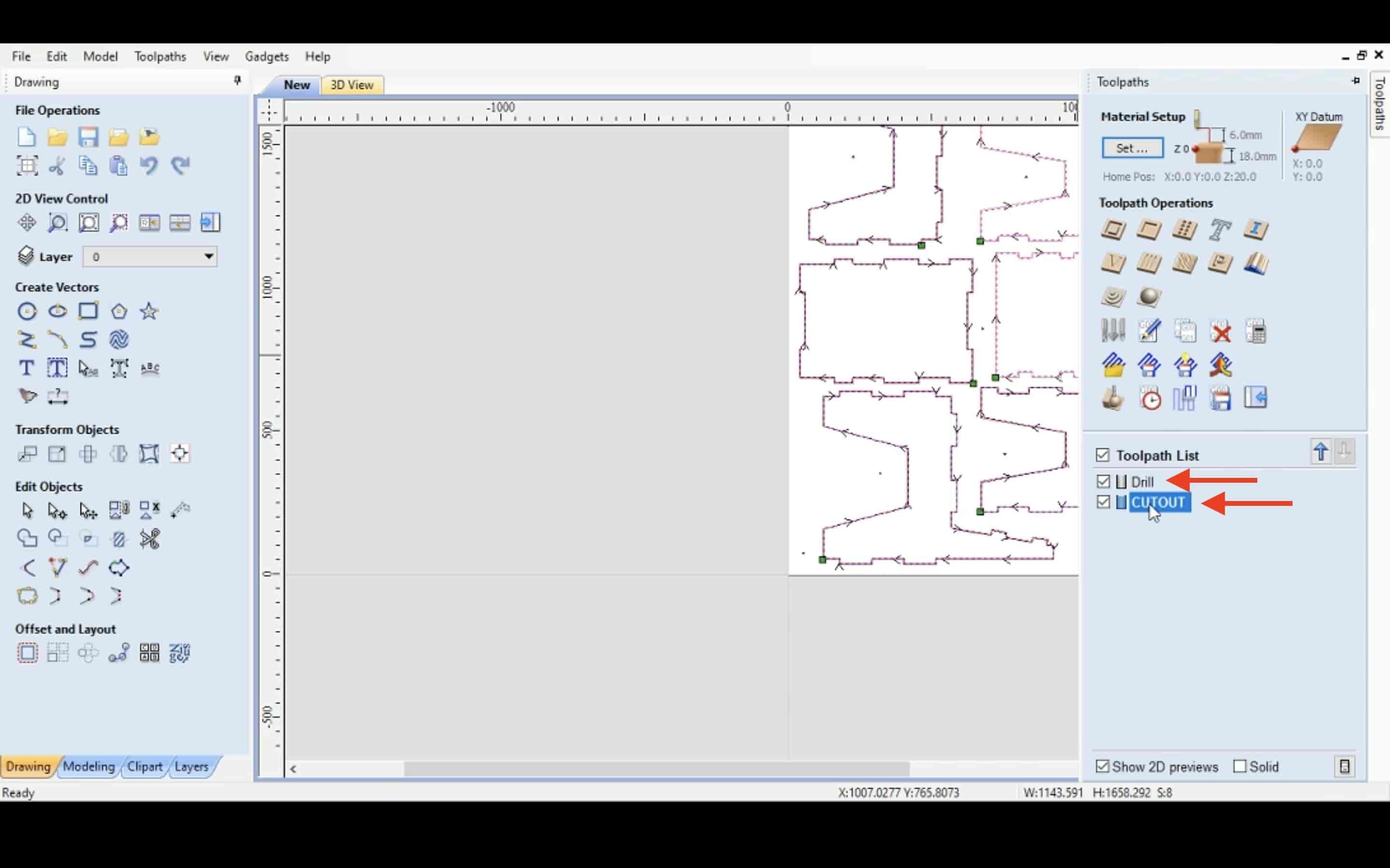
Now, I have two different toolpaths, one for the drills and the other one for the cut.
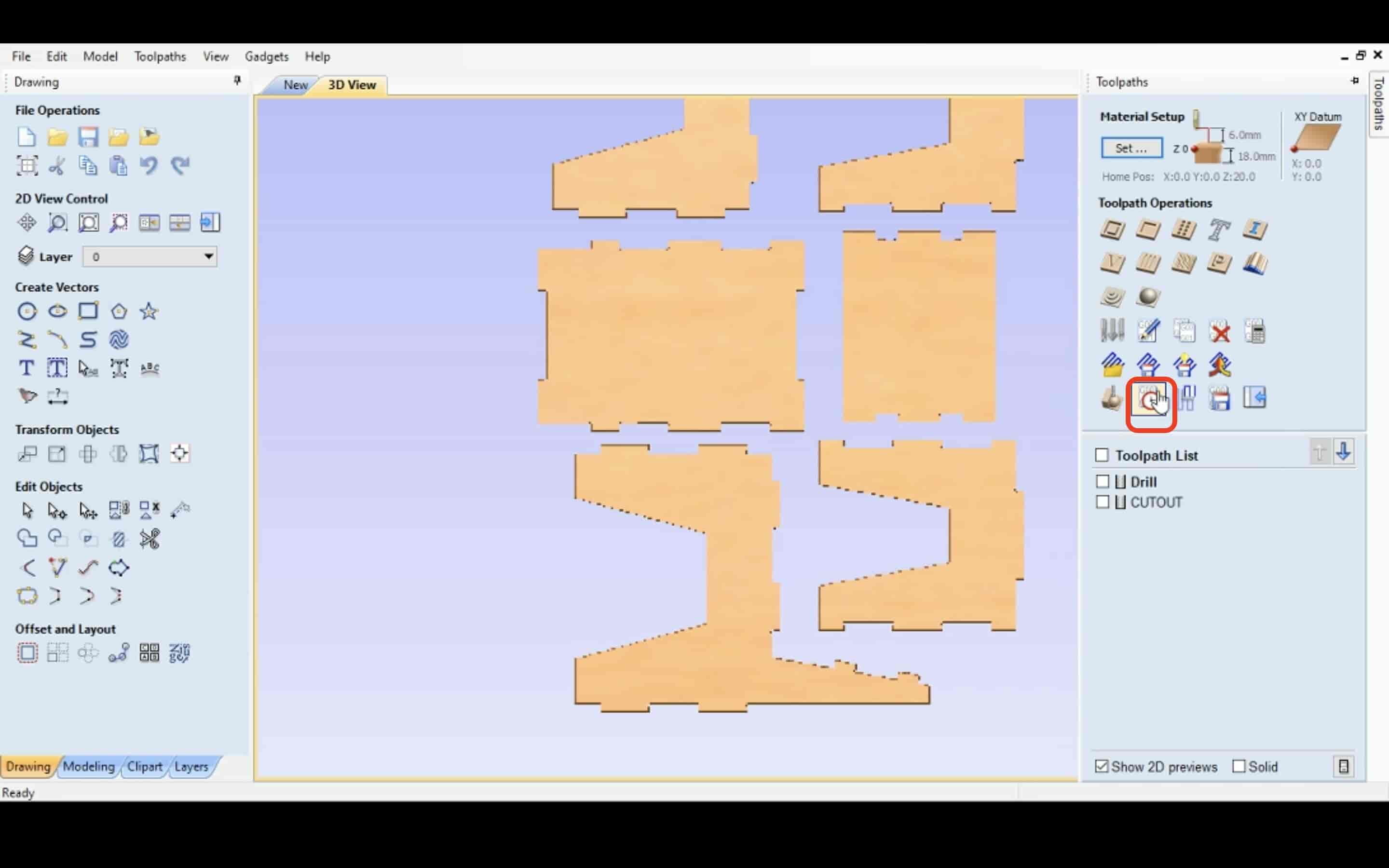
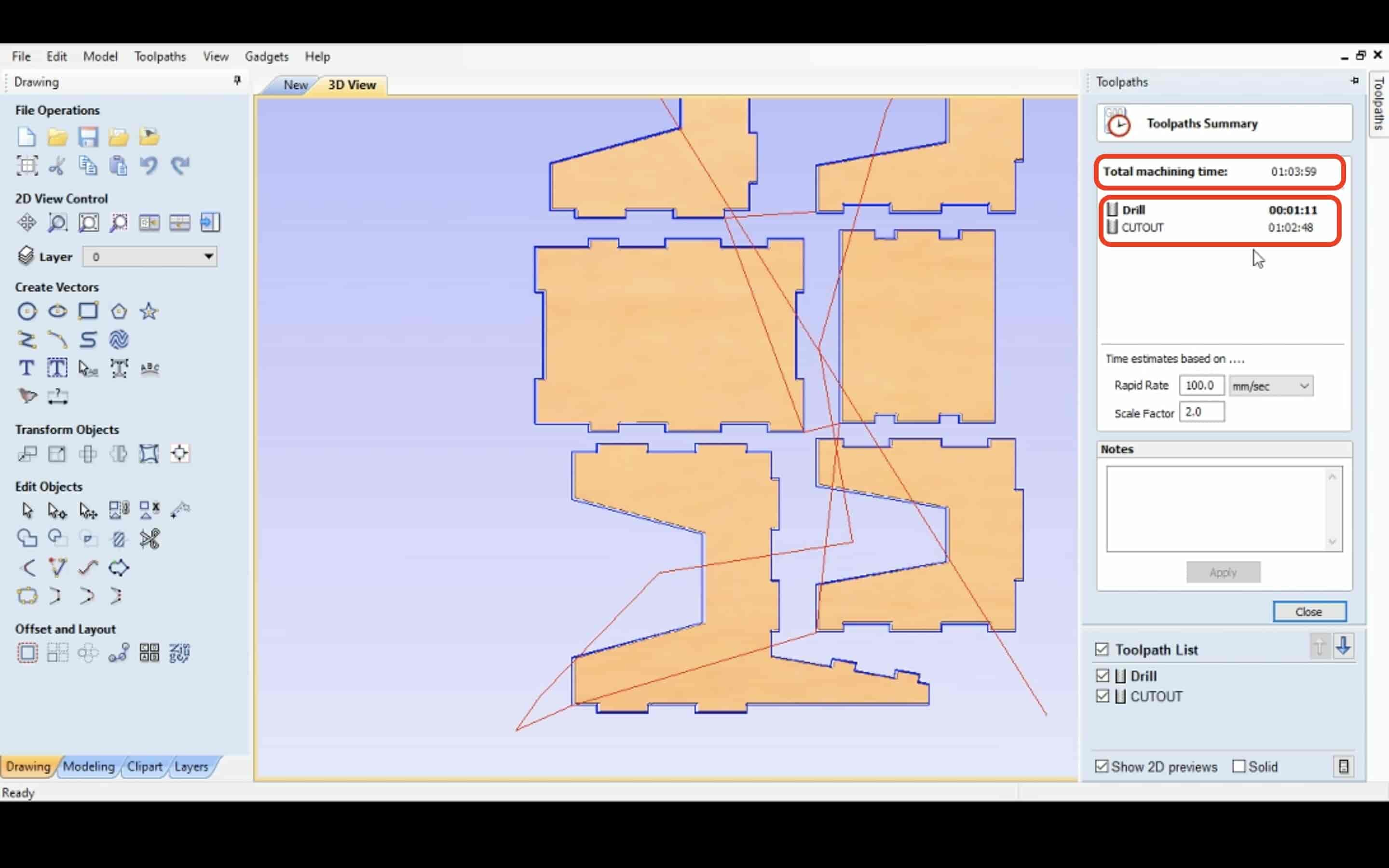
To see the estimation of the working time. Select the toolpaths summary tool. It will display the required time for each job. As we can see, the cutting job will take around one hour and the drills job will take around one minute.
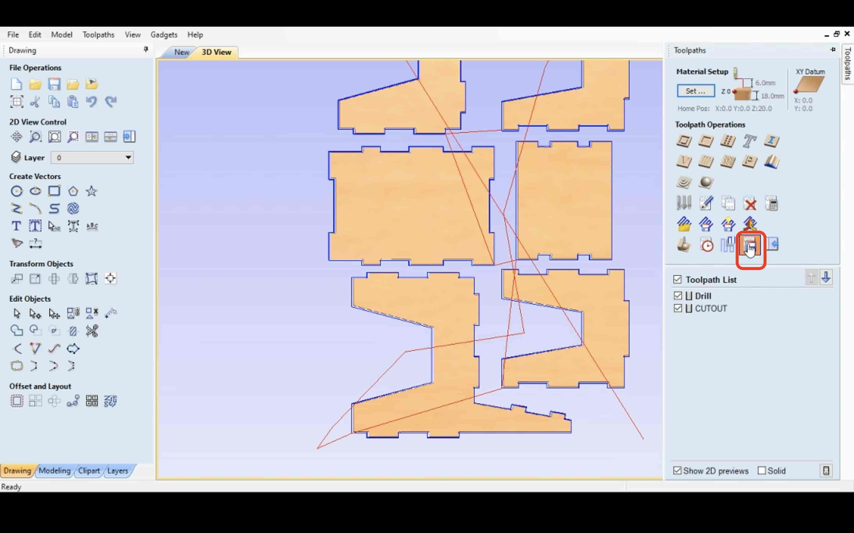
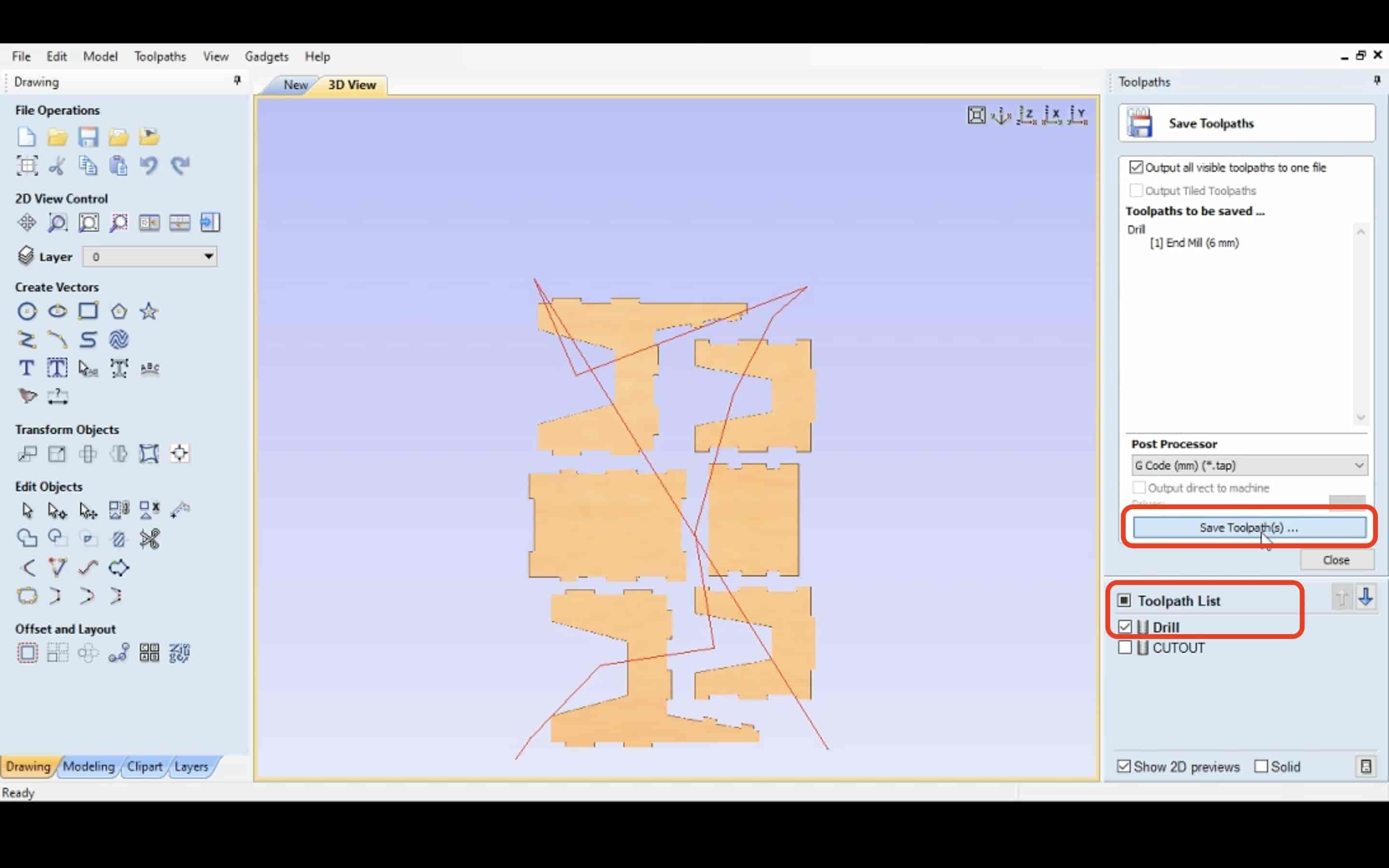
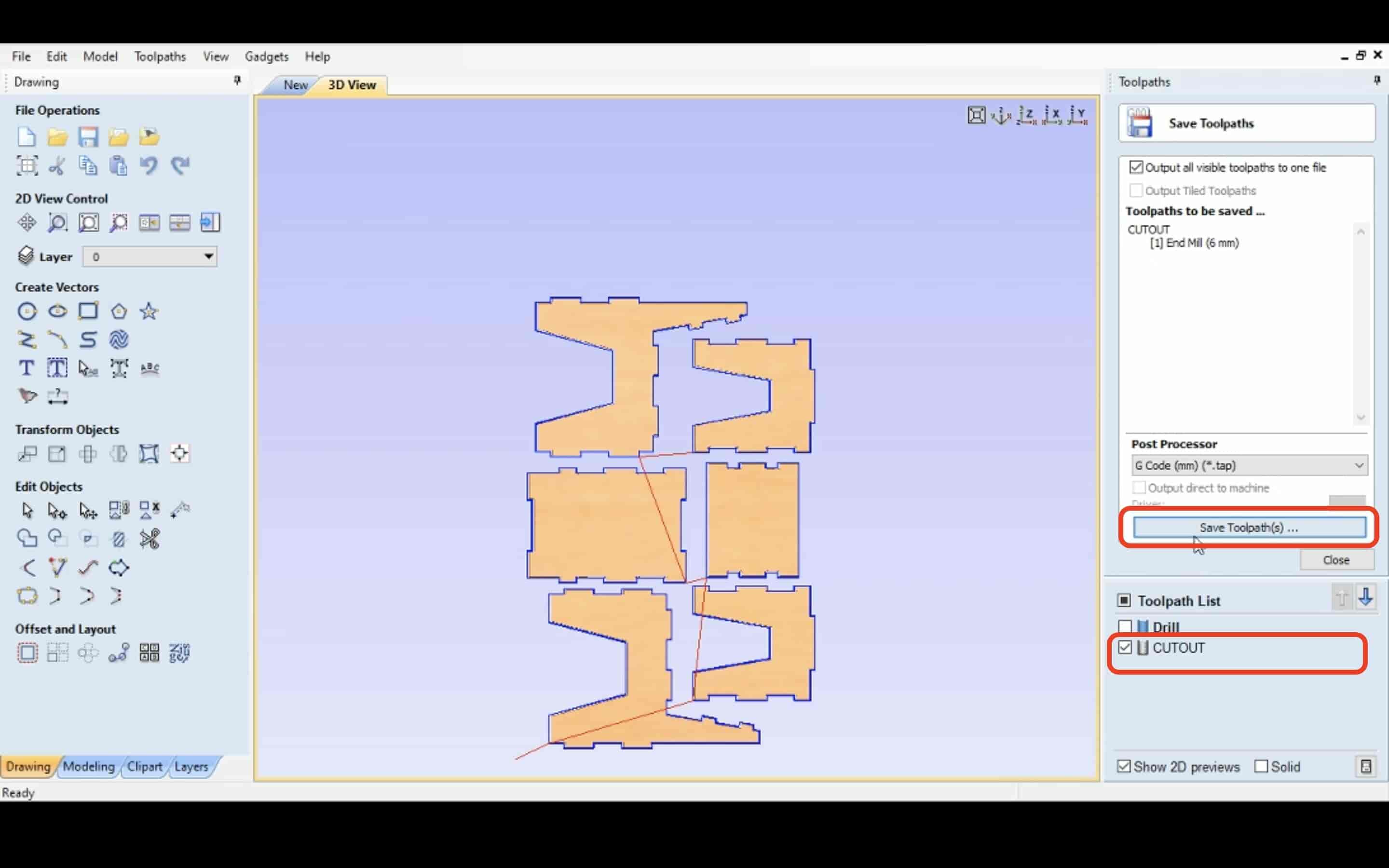
We are ready now to export the Gcode file for each job. Select the save toolpaths tool, then select each job individually and save it’s Gcode file.
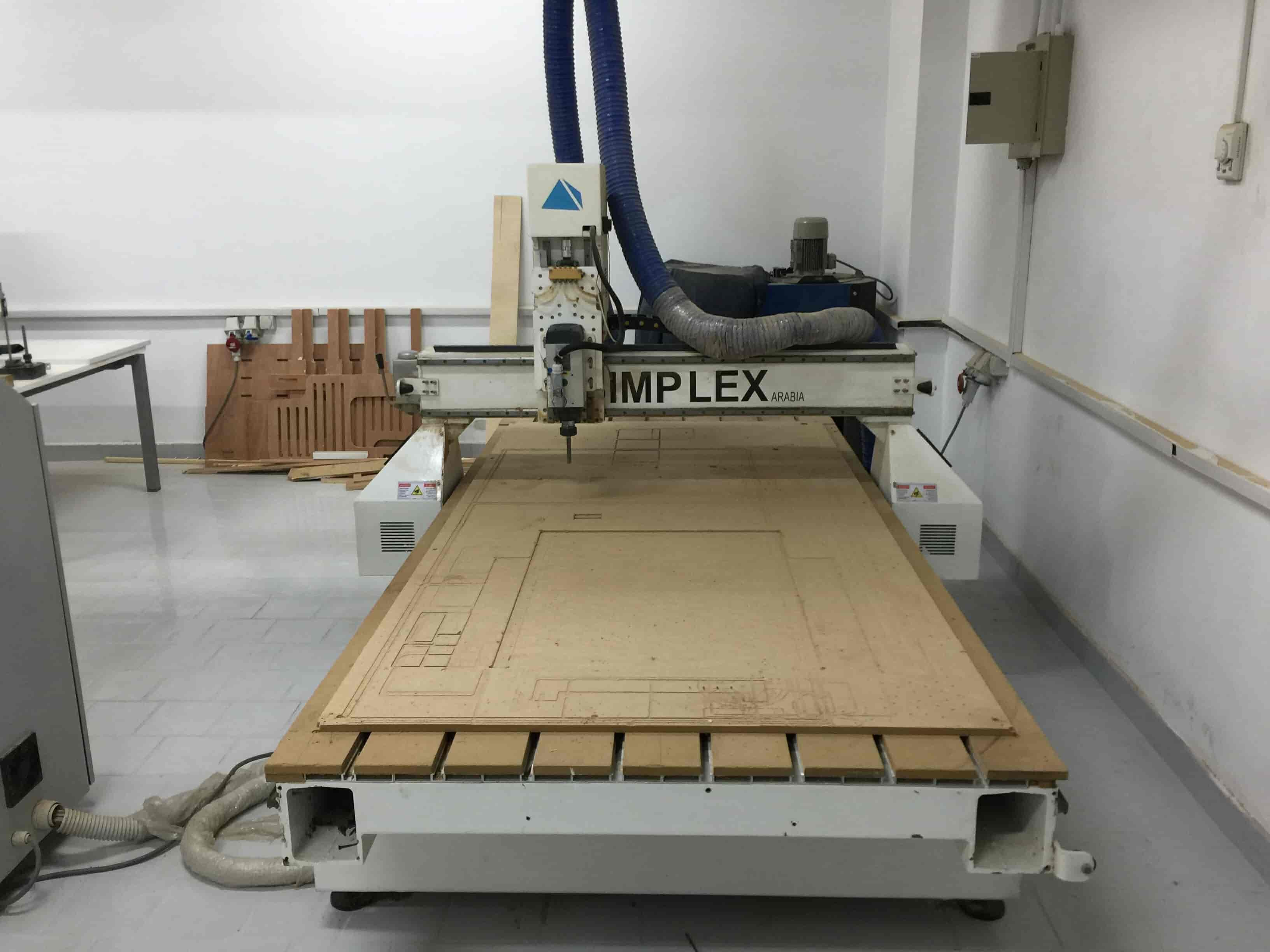
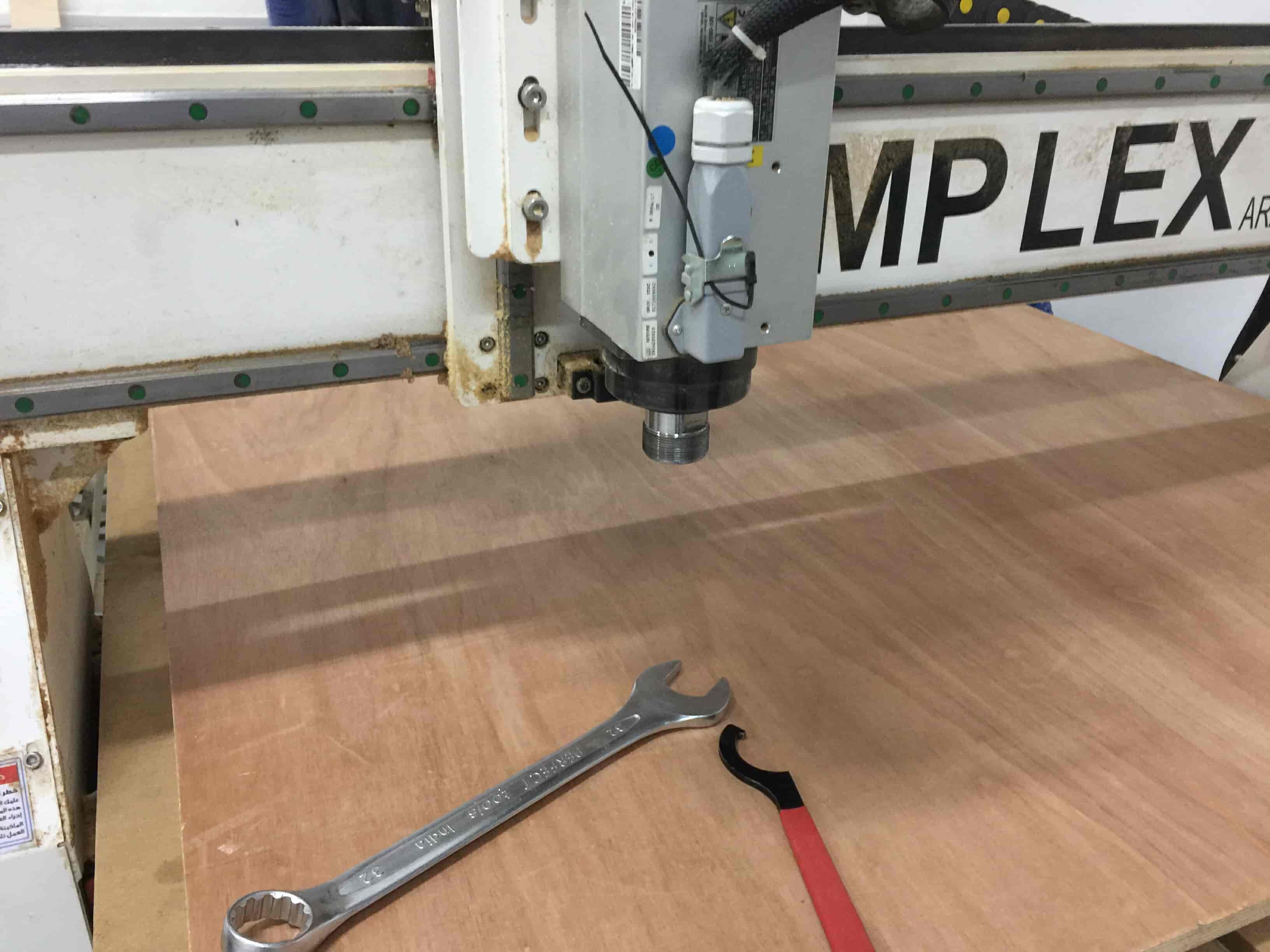
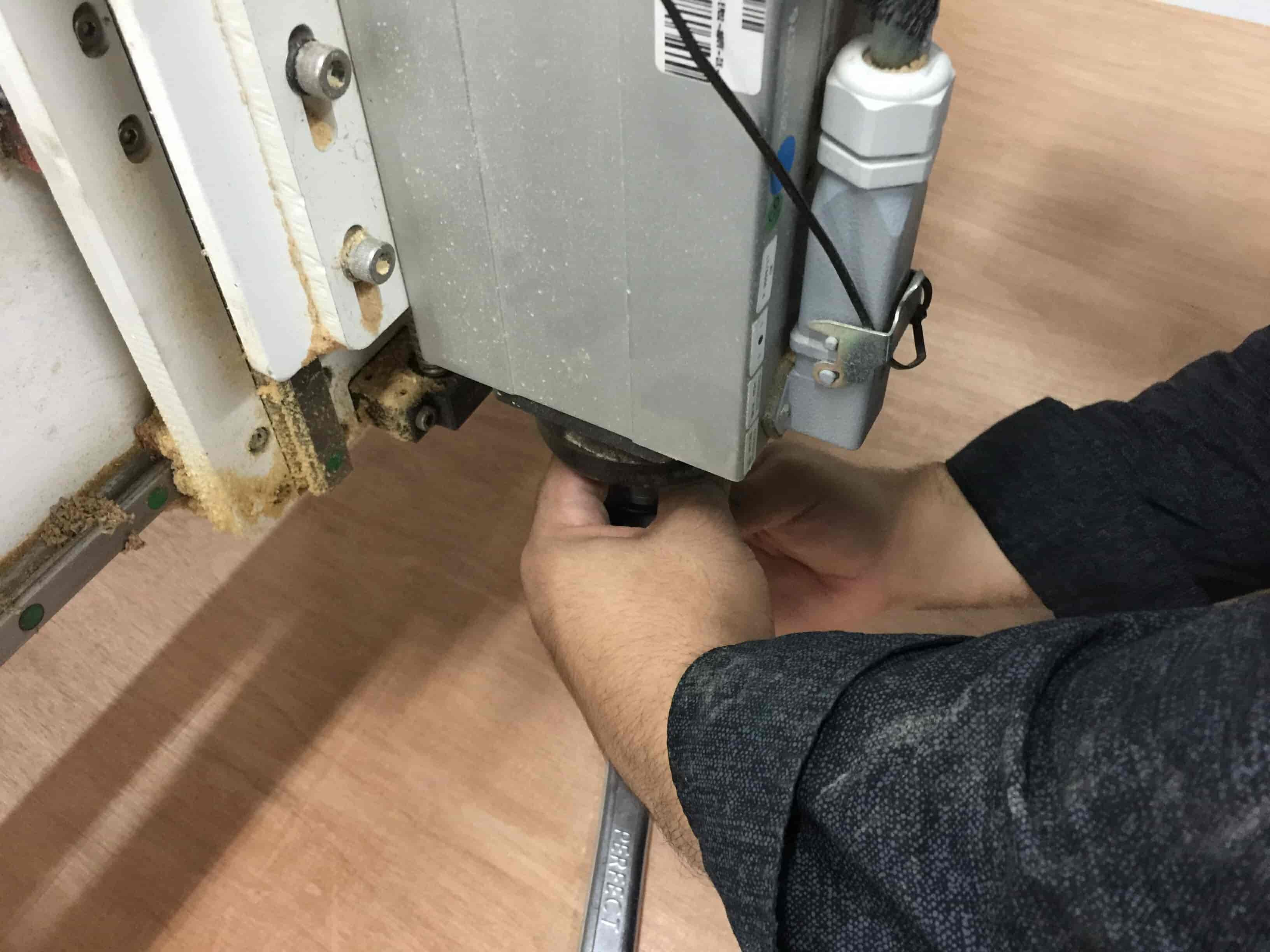
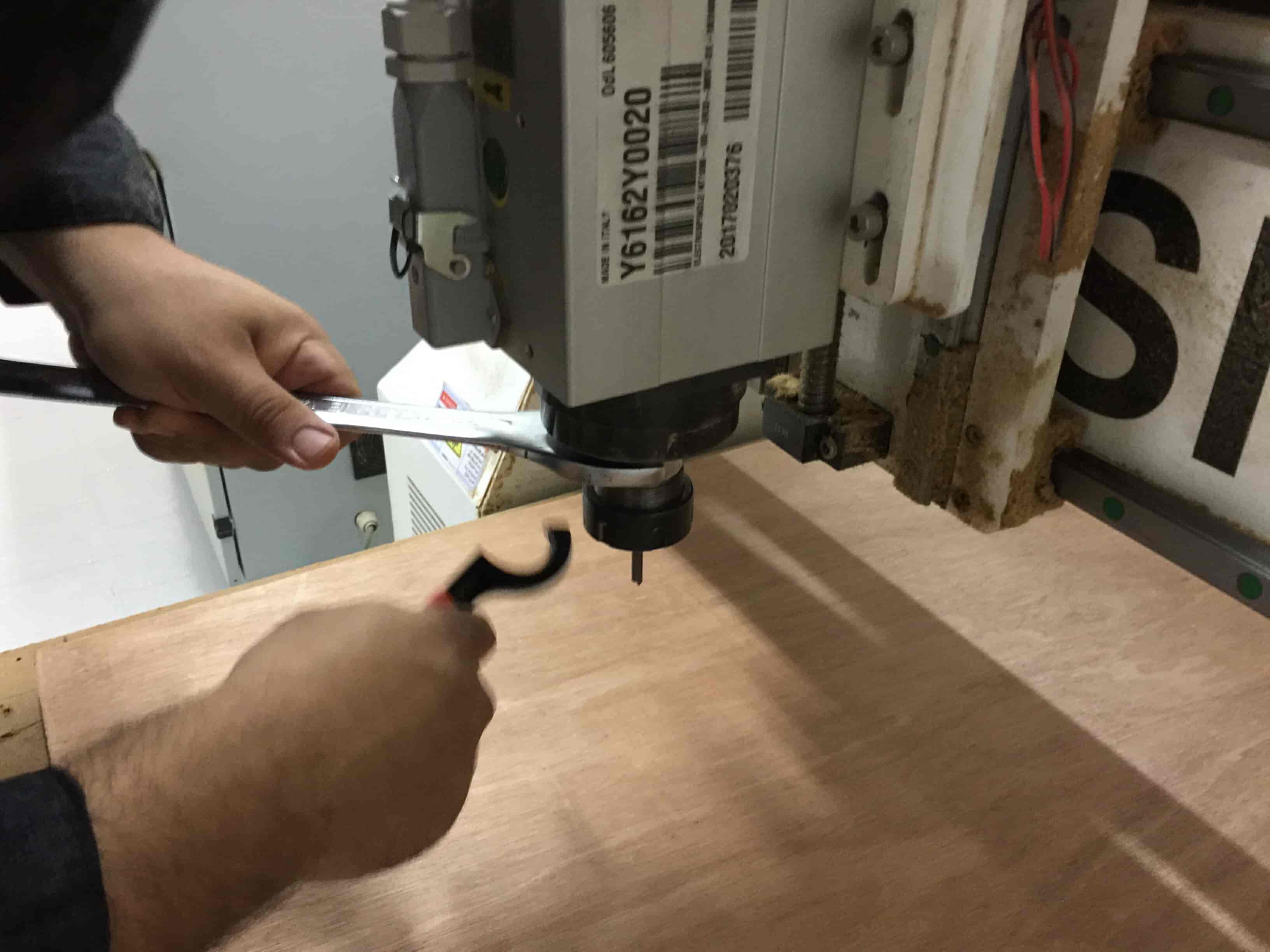
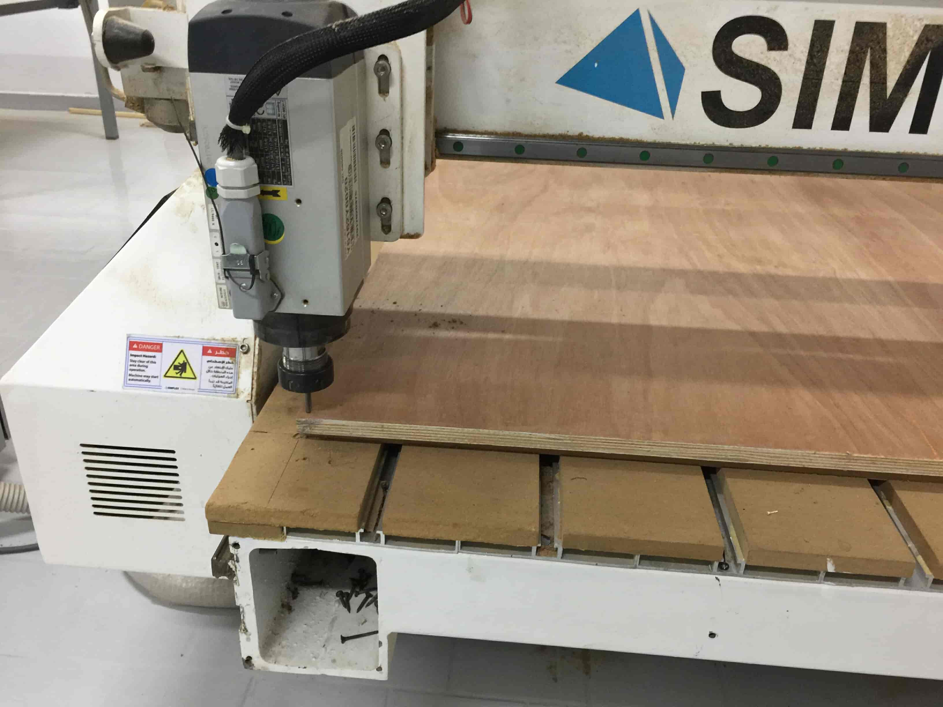
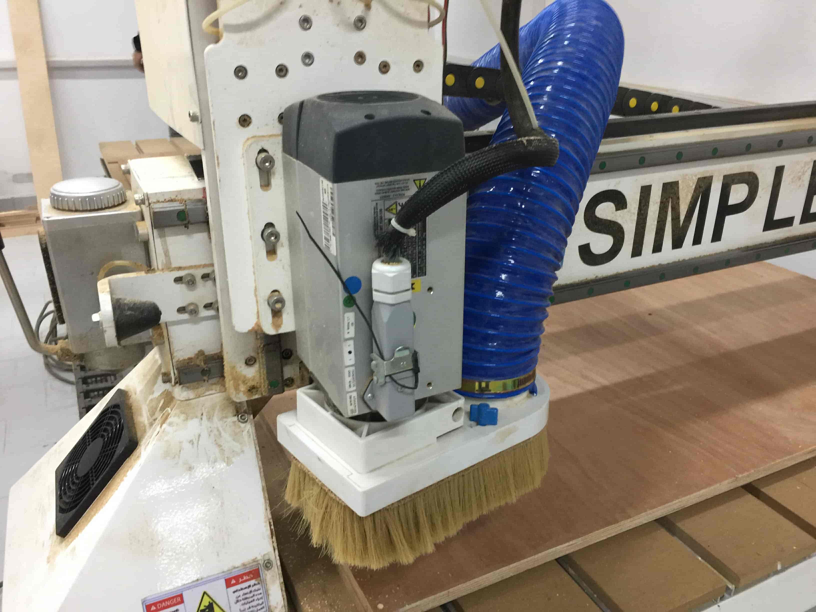
It’s the time to play with the CNC router machine “AKA the beast“. First thing, I installed the 6mm endmill.
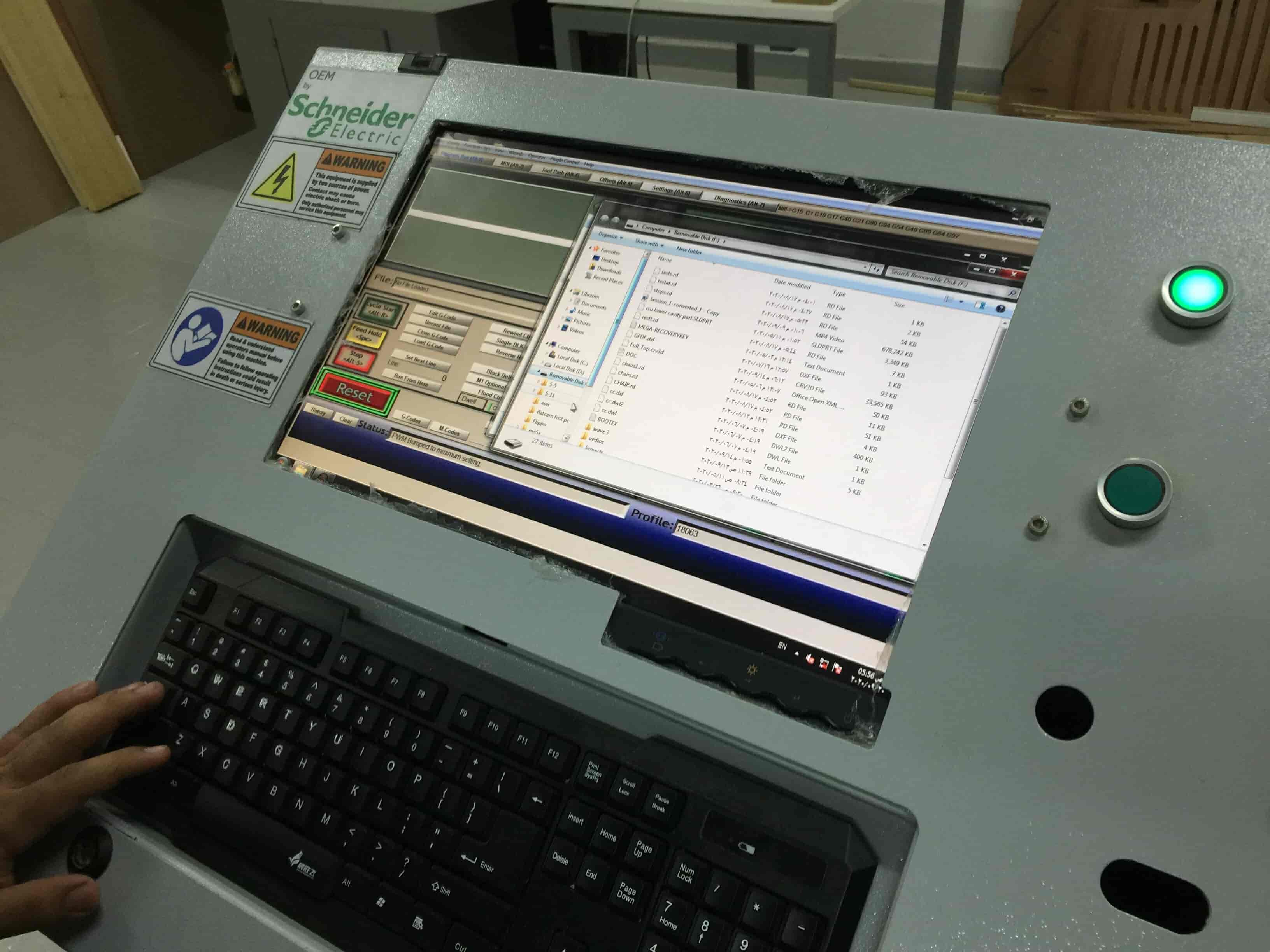
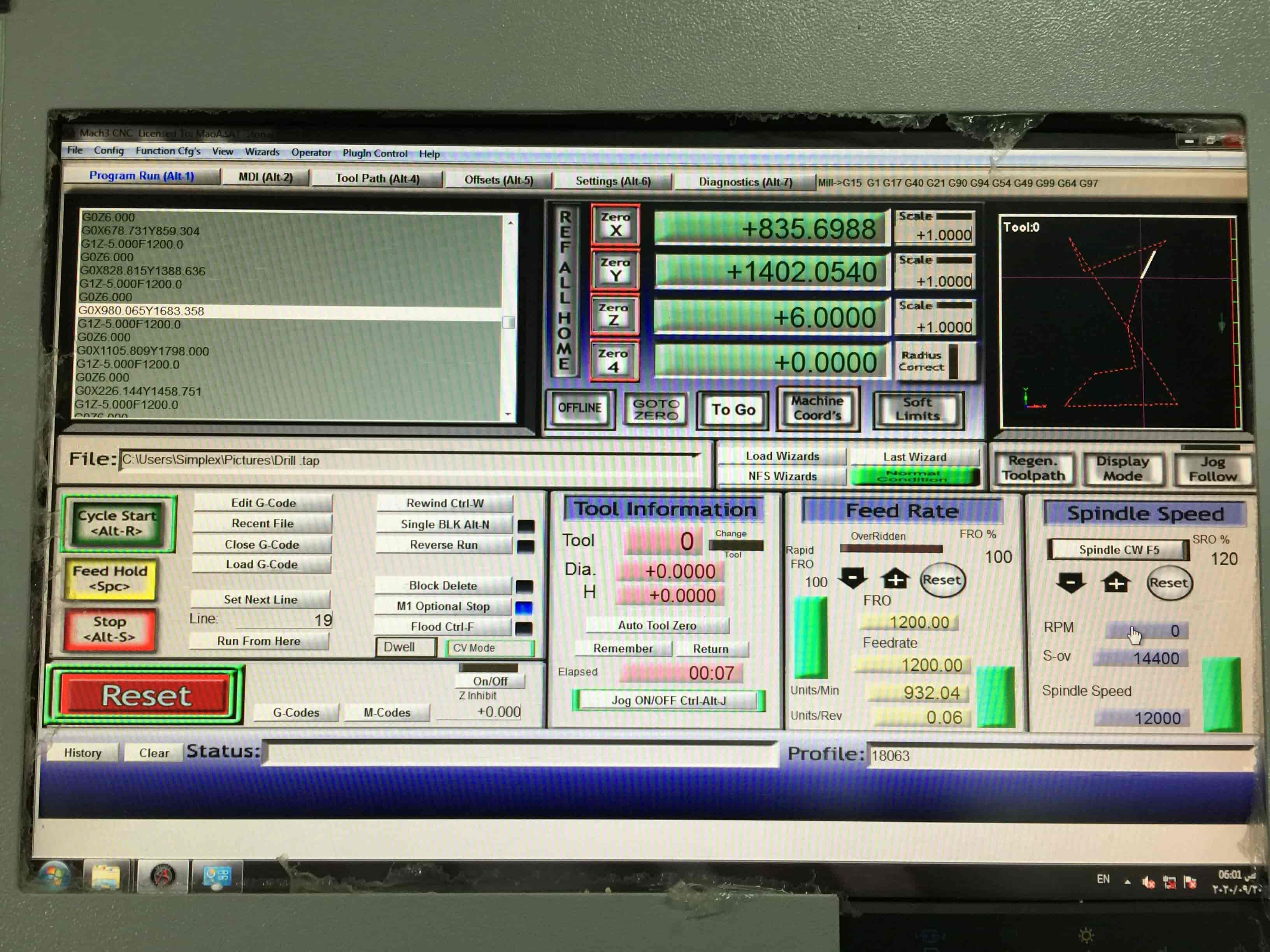
Then, I used the MACH3 software to operate the machine with the help of my boy Maichel. I homed the machine.
I imported the drills Gcode file in the MACH3 software and started the job.
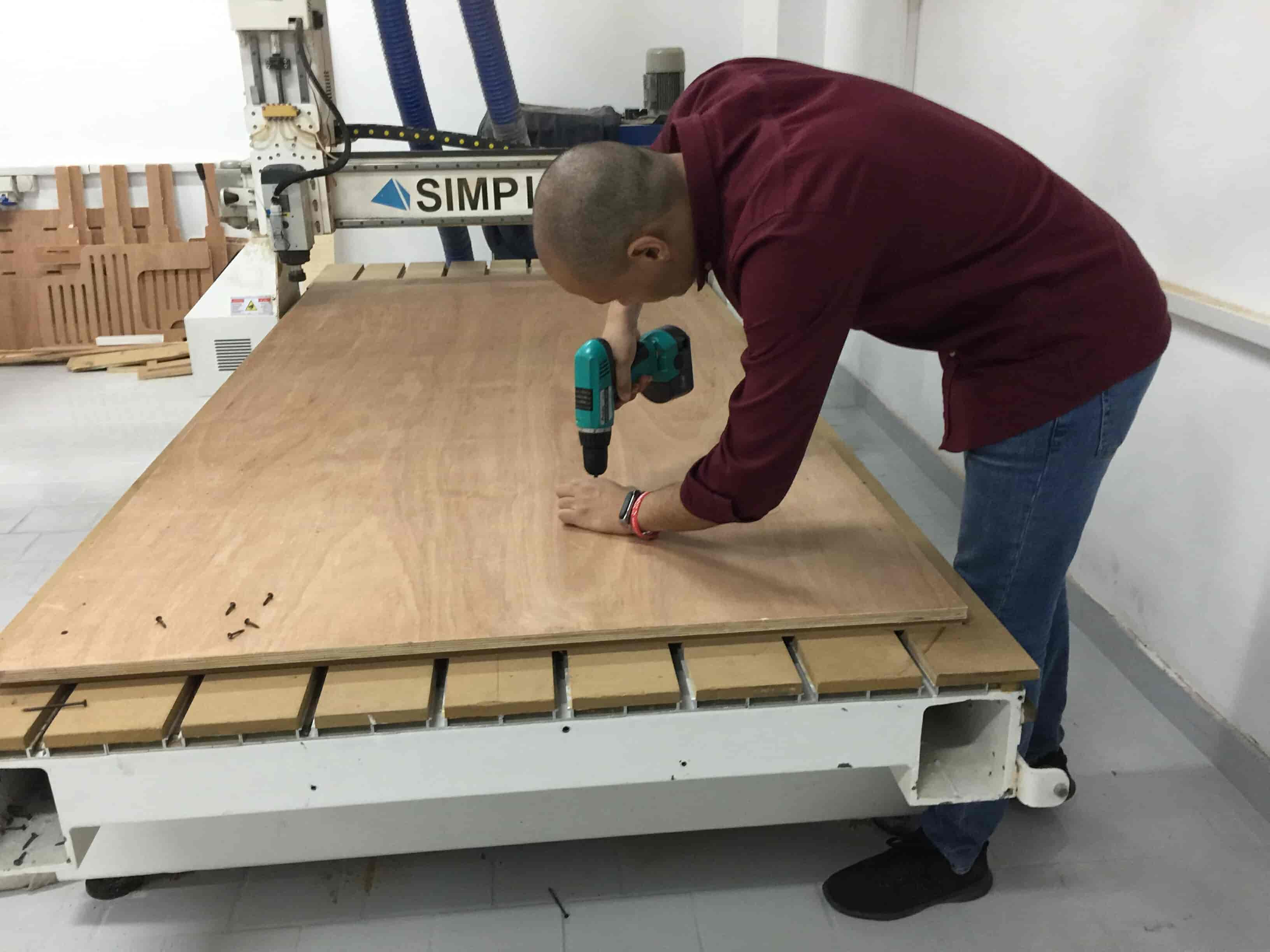
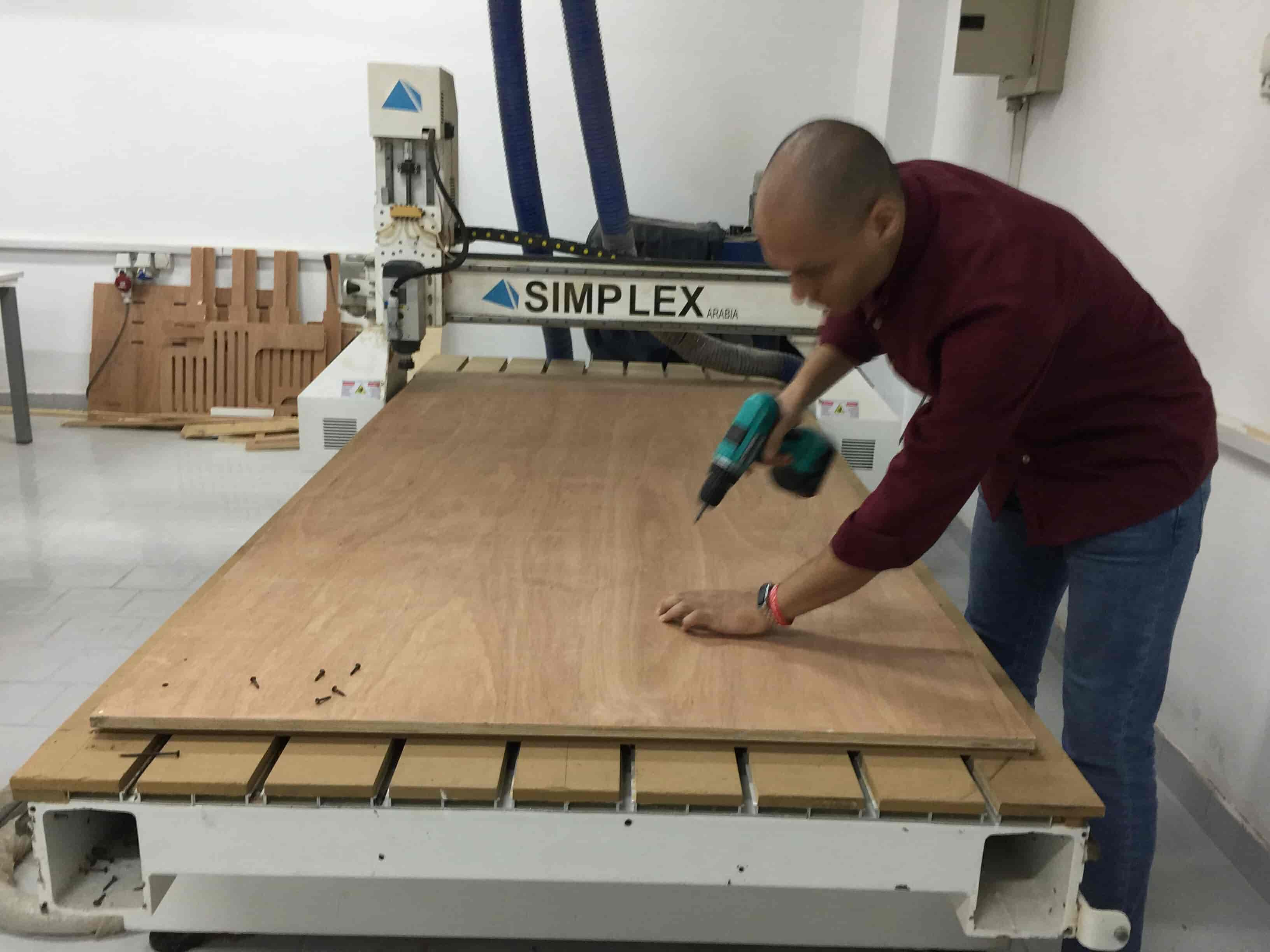
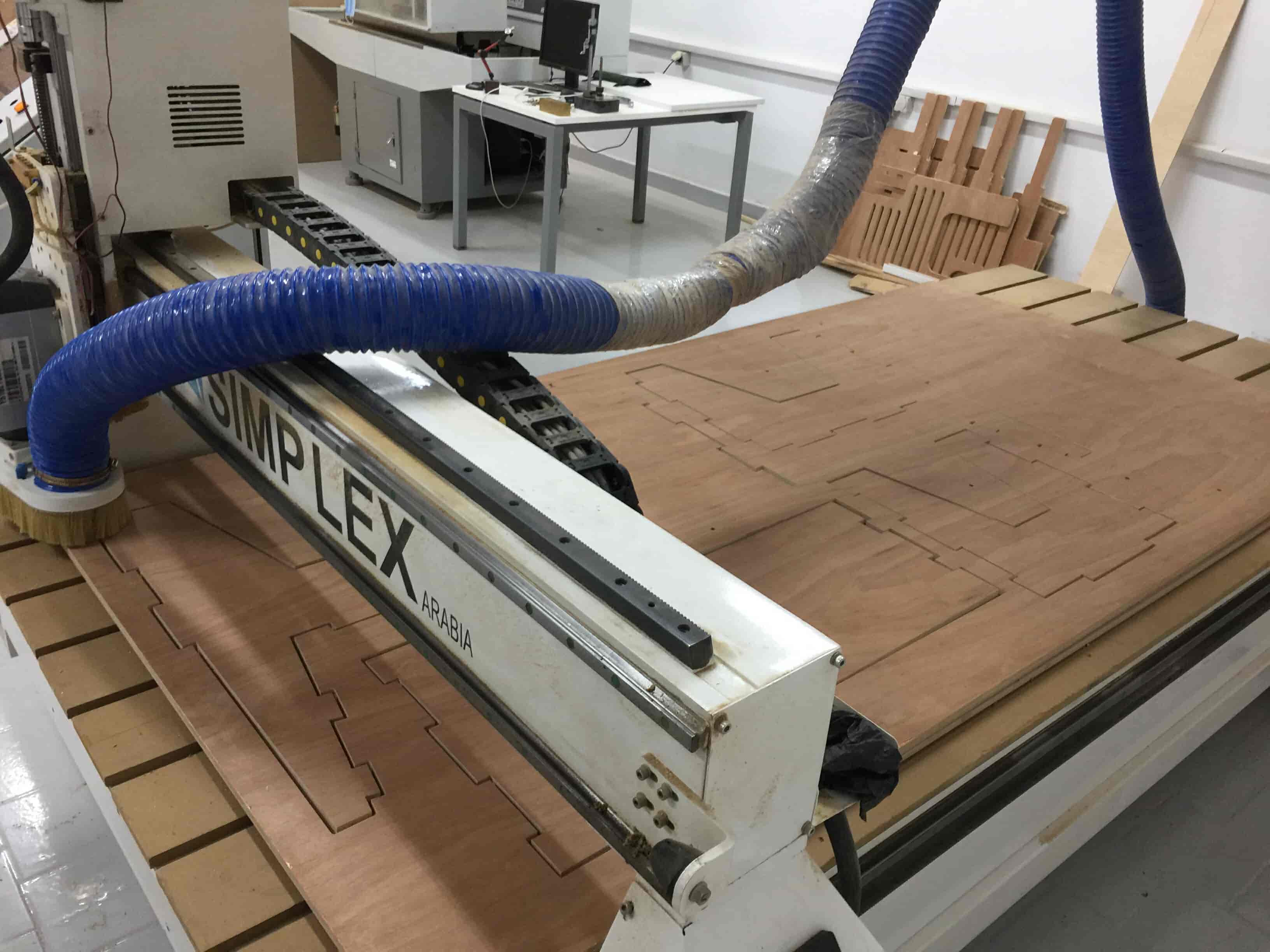
After that I secured the wood sheet on the machine bed with some screws and a cordless screwdriver.
Then I homed the machine again and imported the cut Gcode file and started the job.
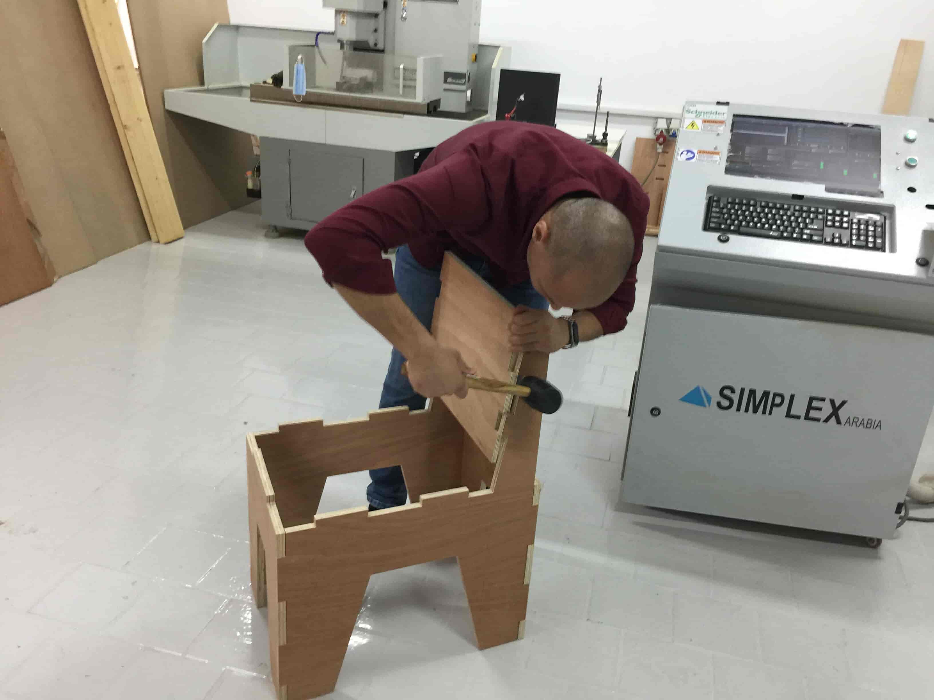
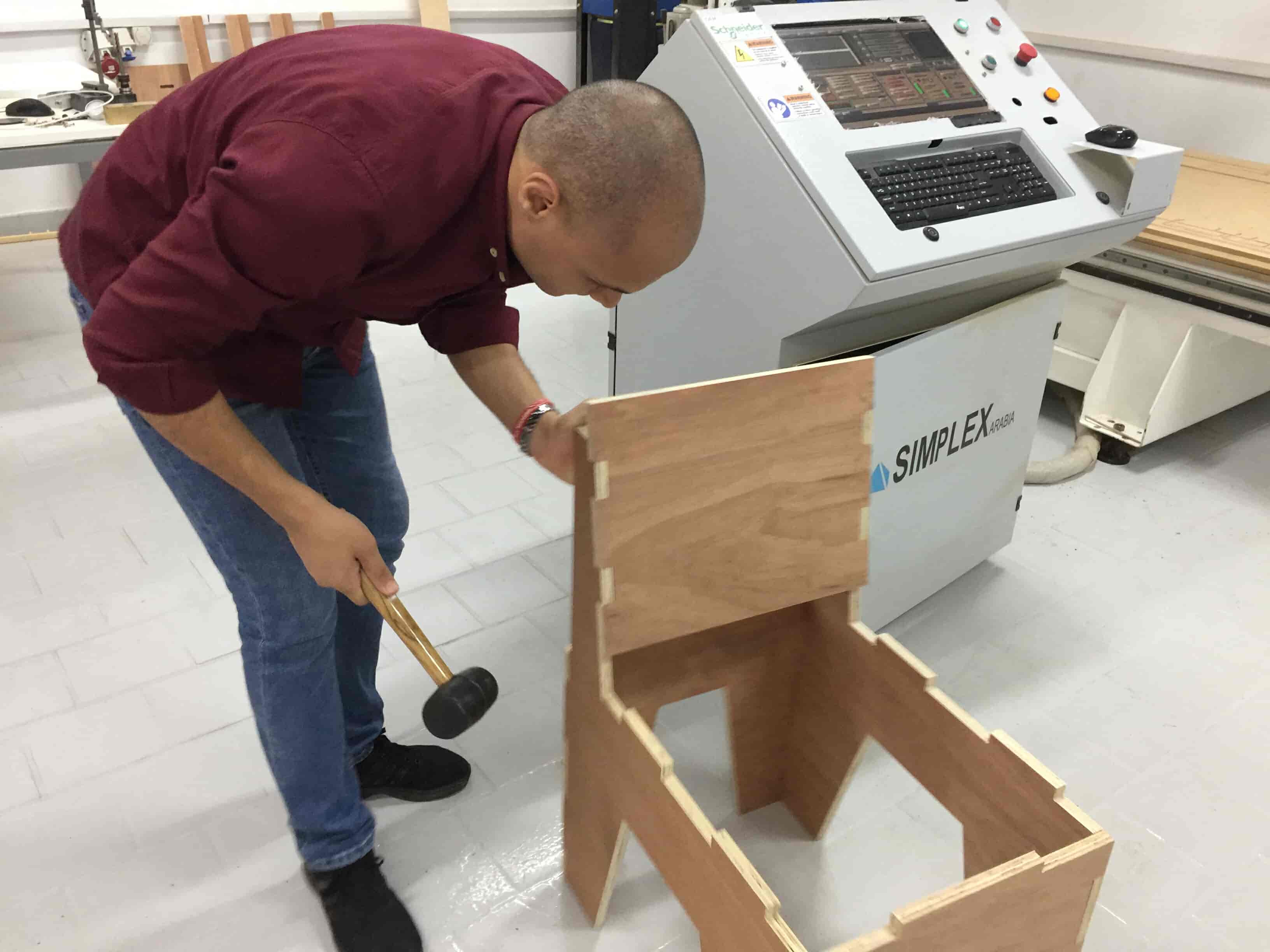
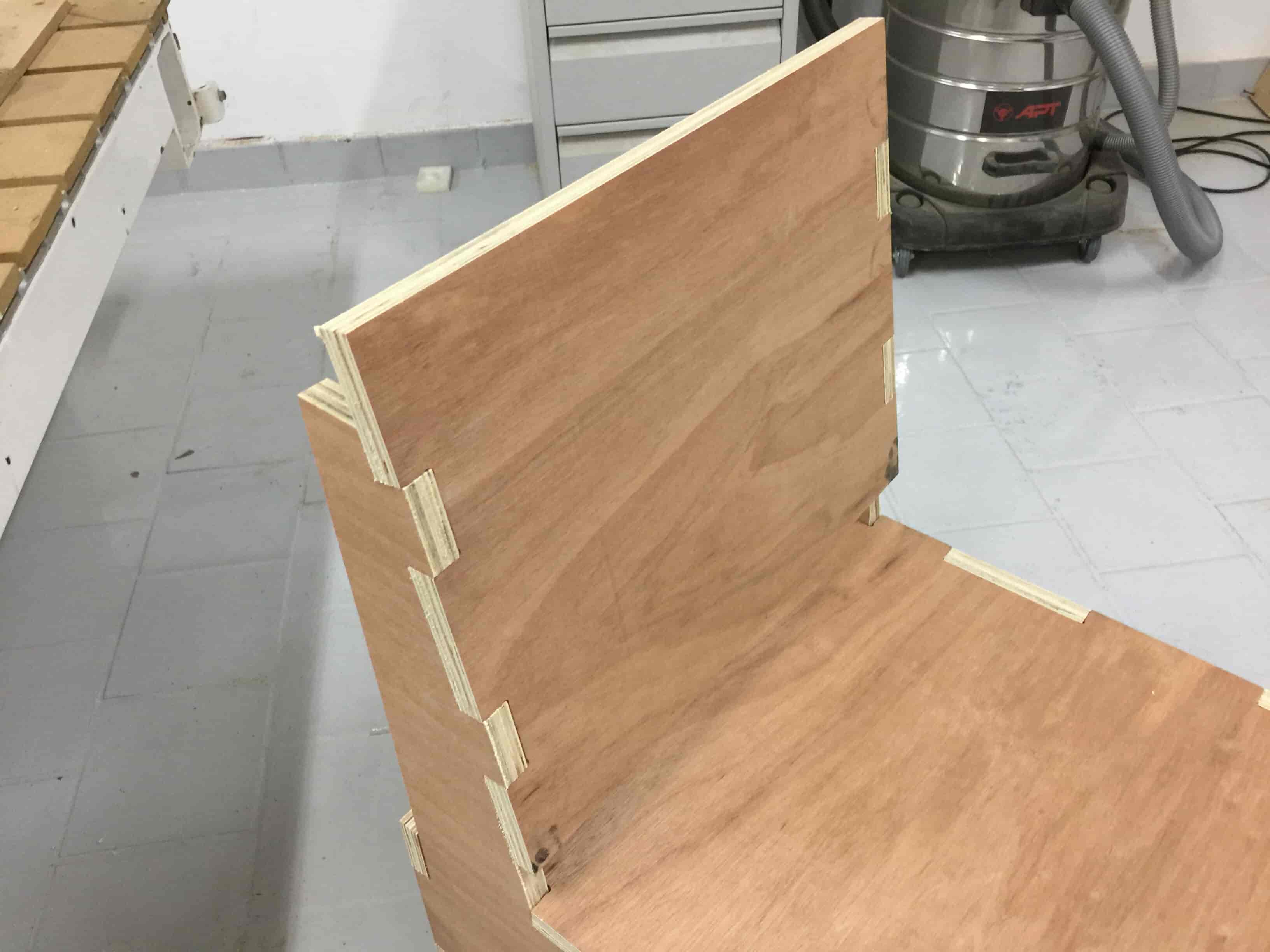
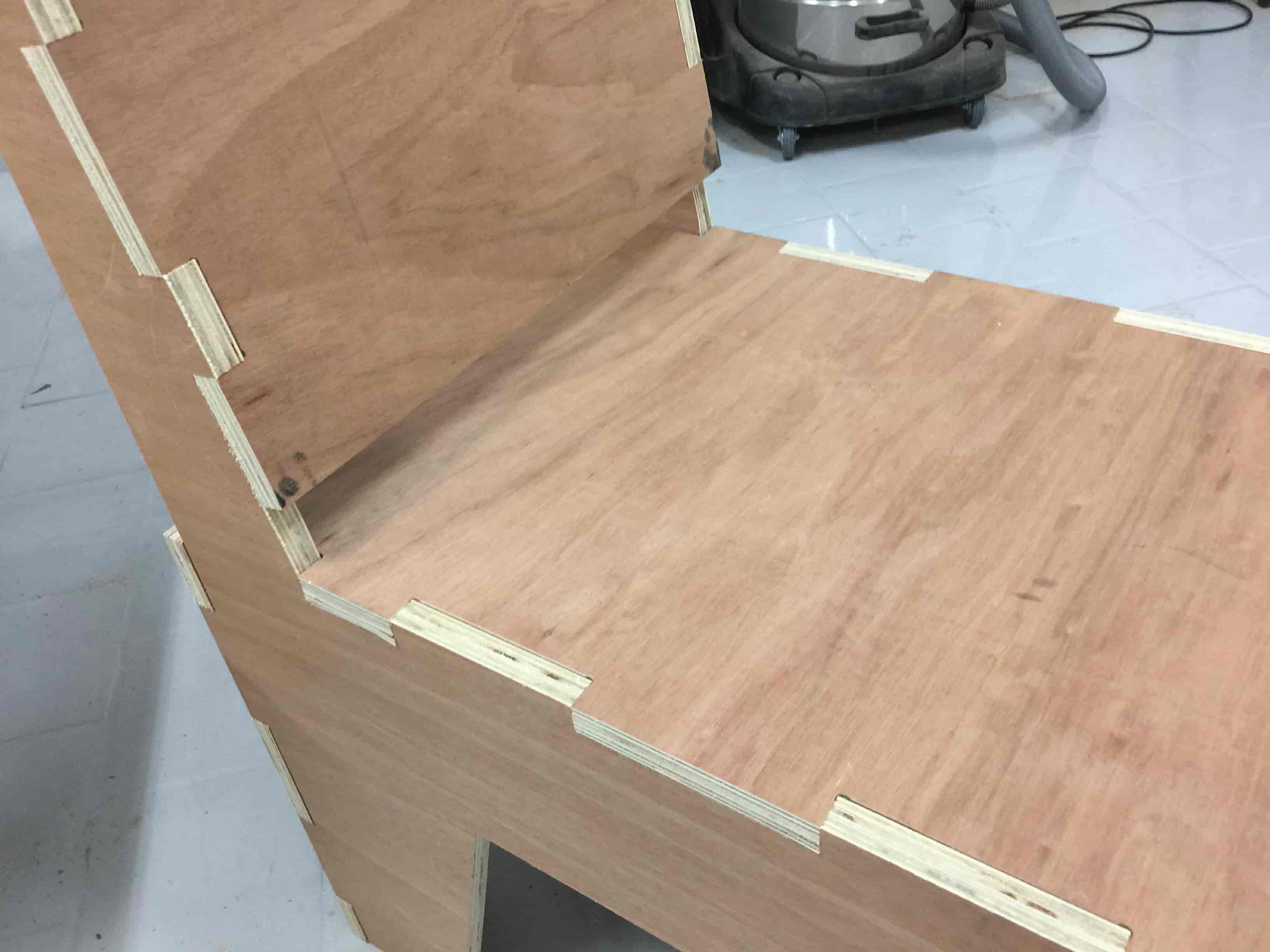
After the machine finished, I started to assemble the coolest chair ever. And I was impressed by the final result. Everything fits cleanly without any need to sand or edit anything. The chair is very solid without any need to use any type of glue or screws or anything!
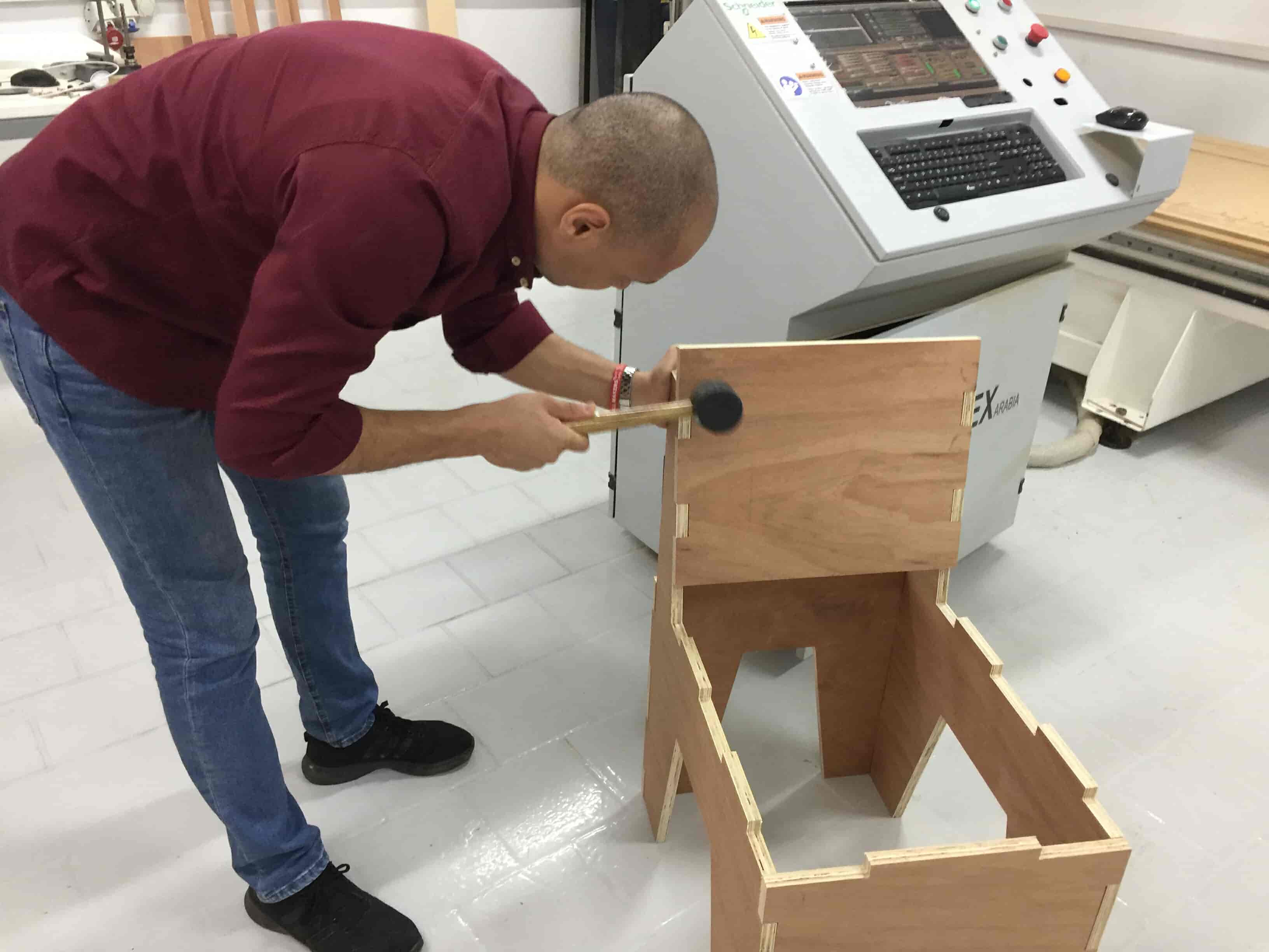
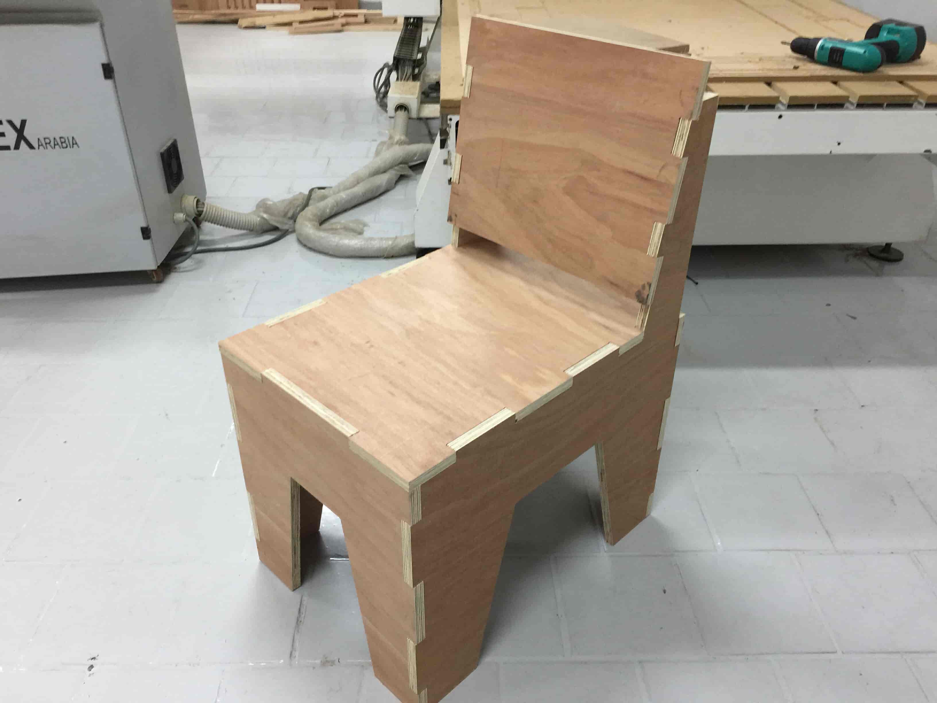
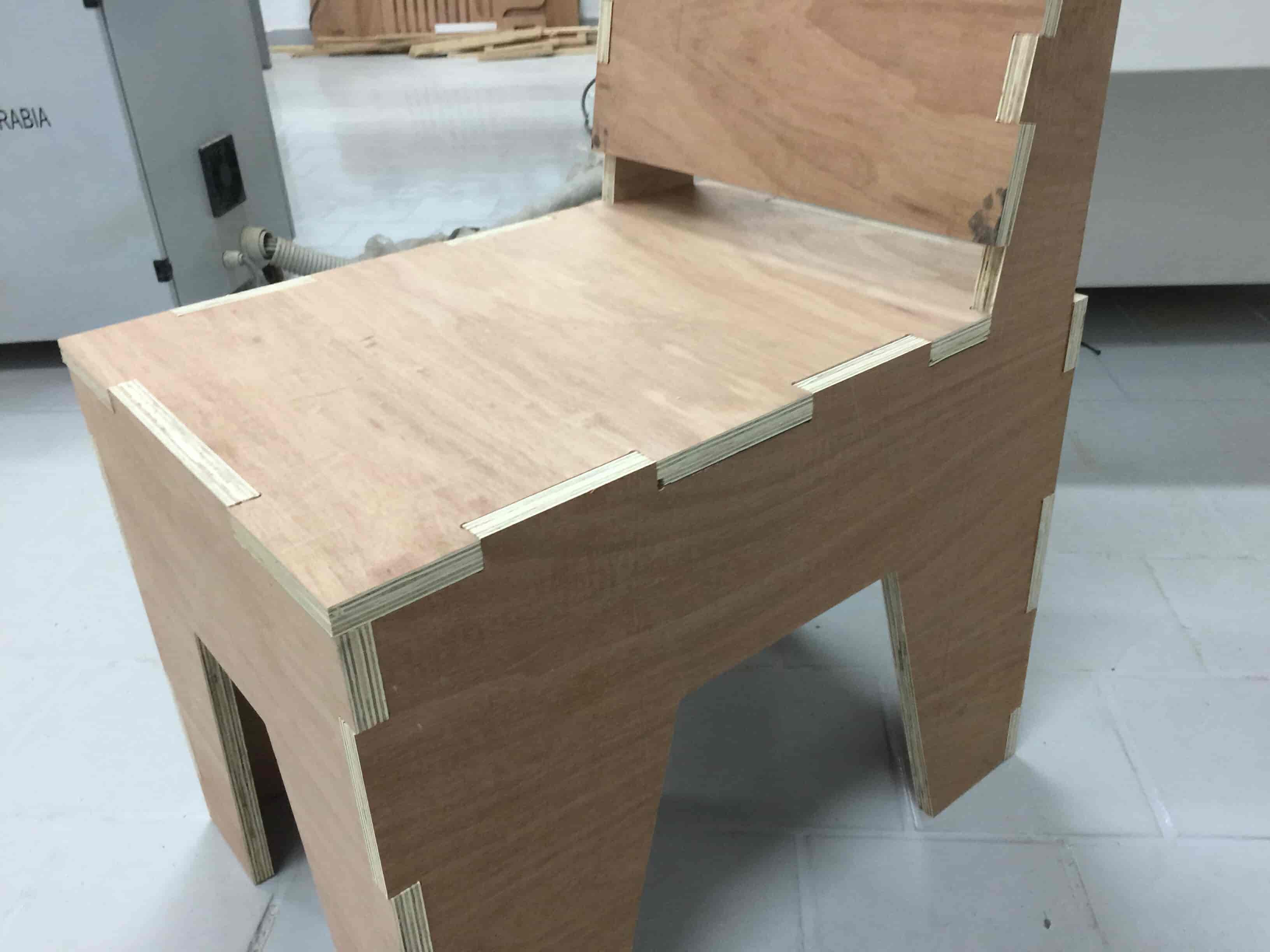
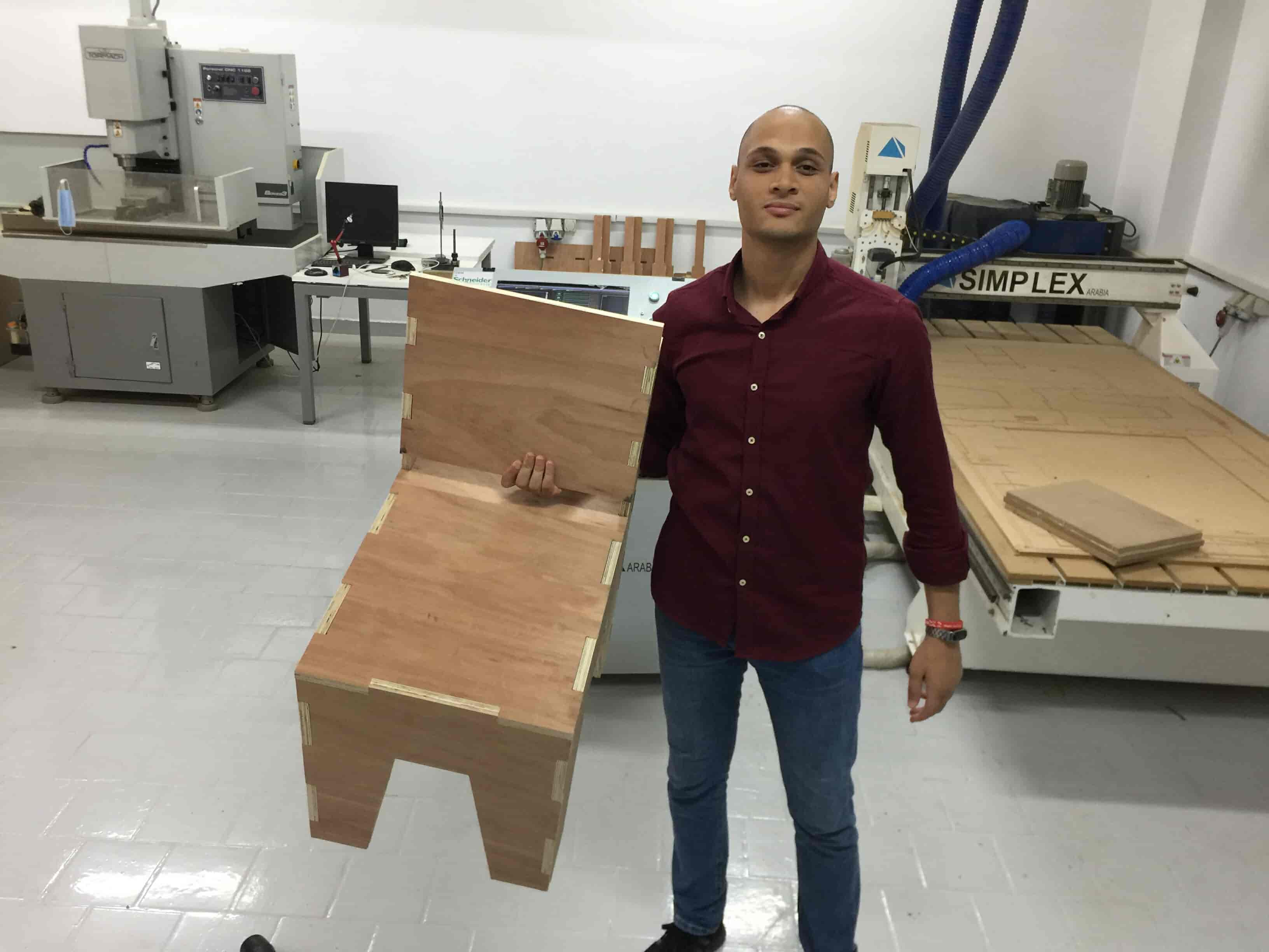
Here’s the chair after the assembly got done.
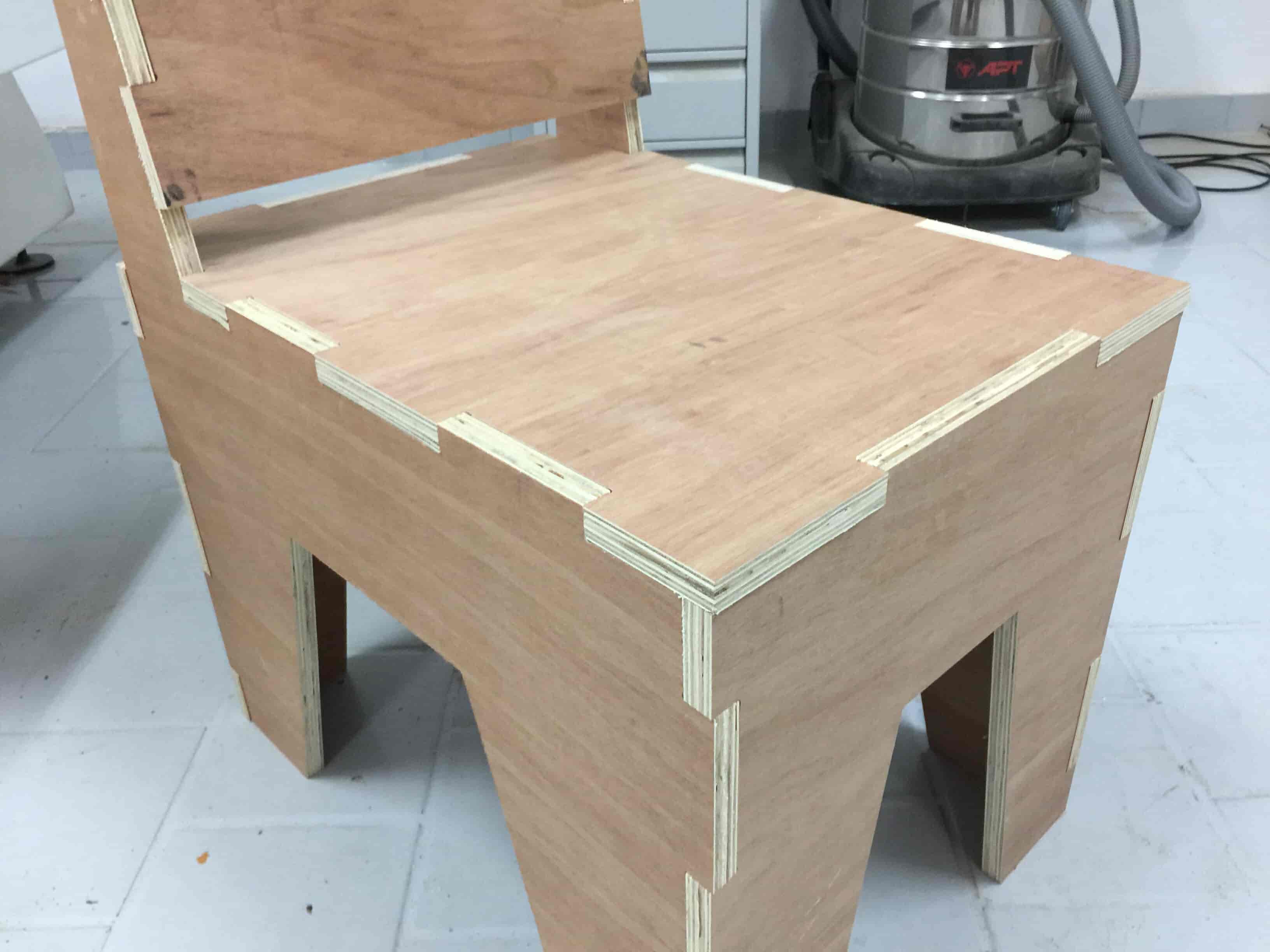
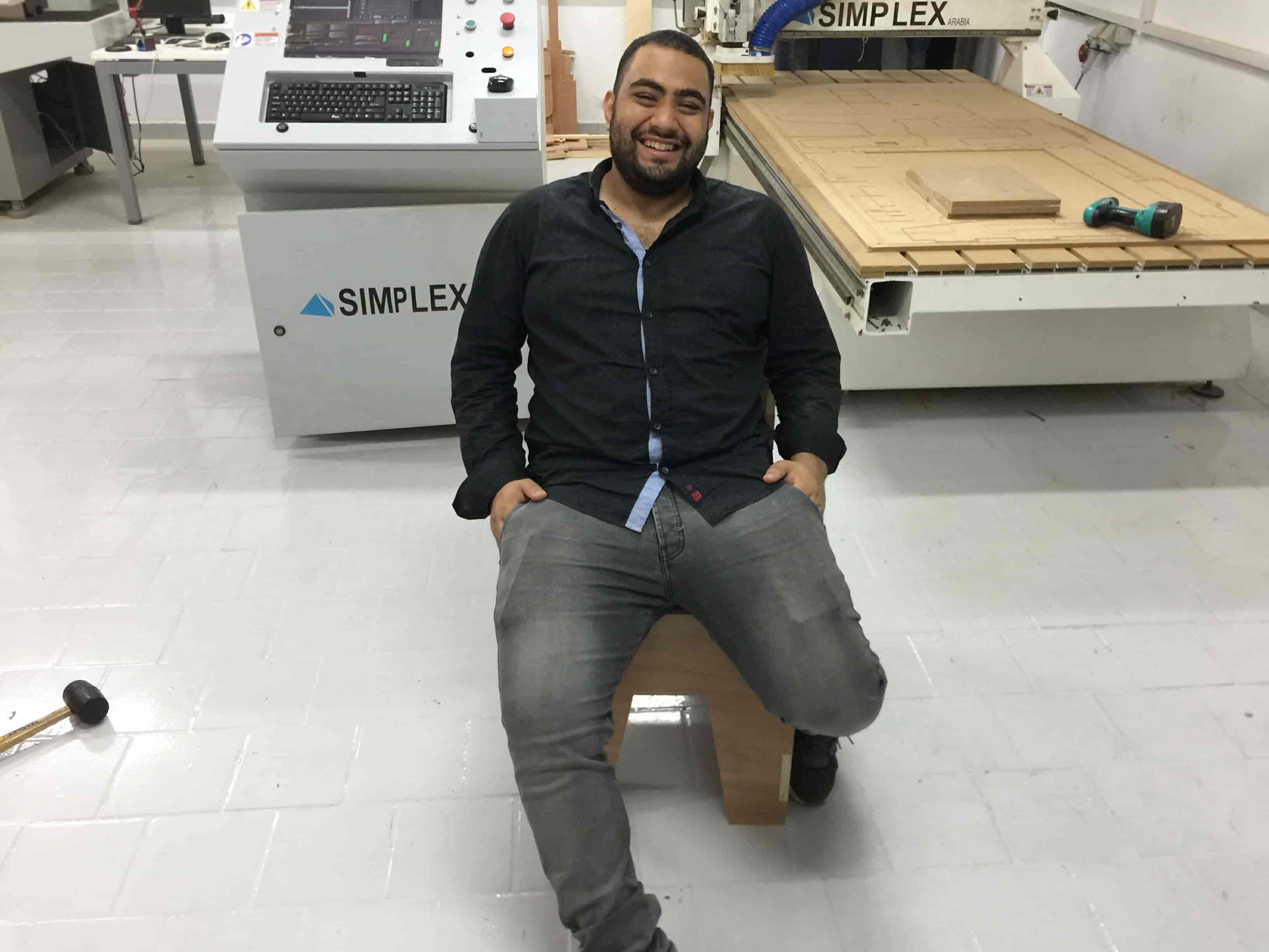
And here’s the coolest chair ever in-action :D
Useful links: