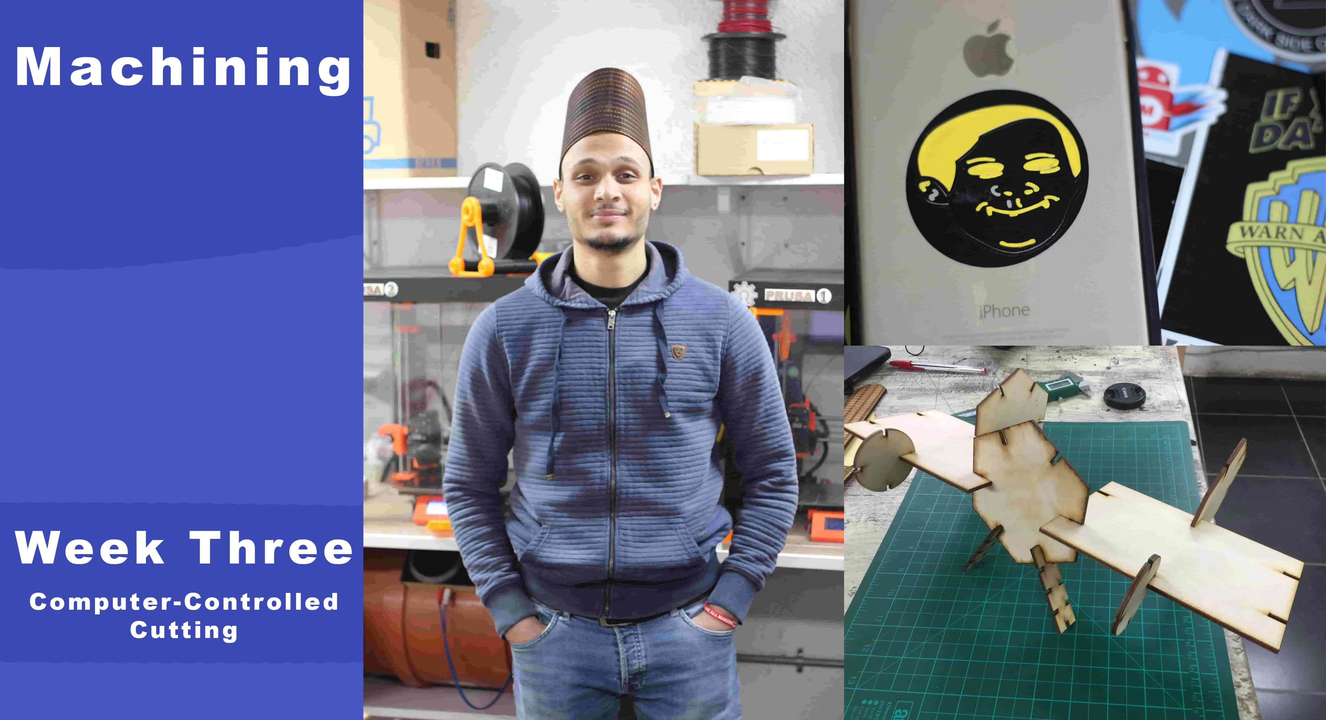
Computer-Controlled Cutting
What’s going on?
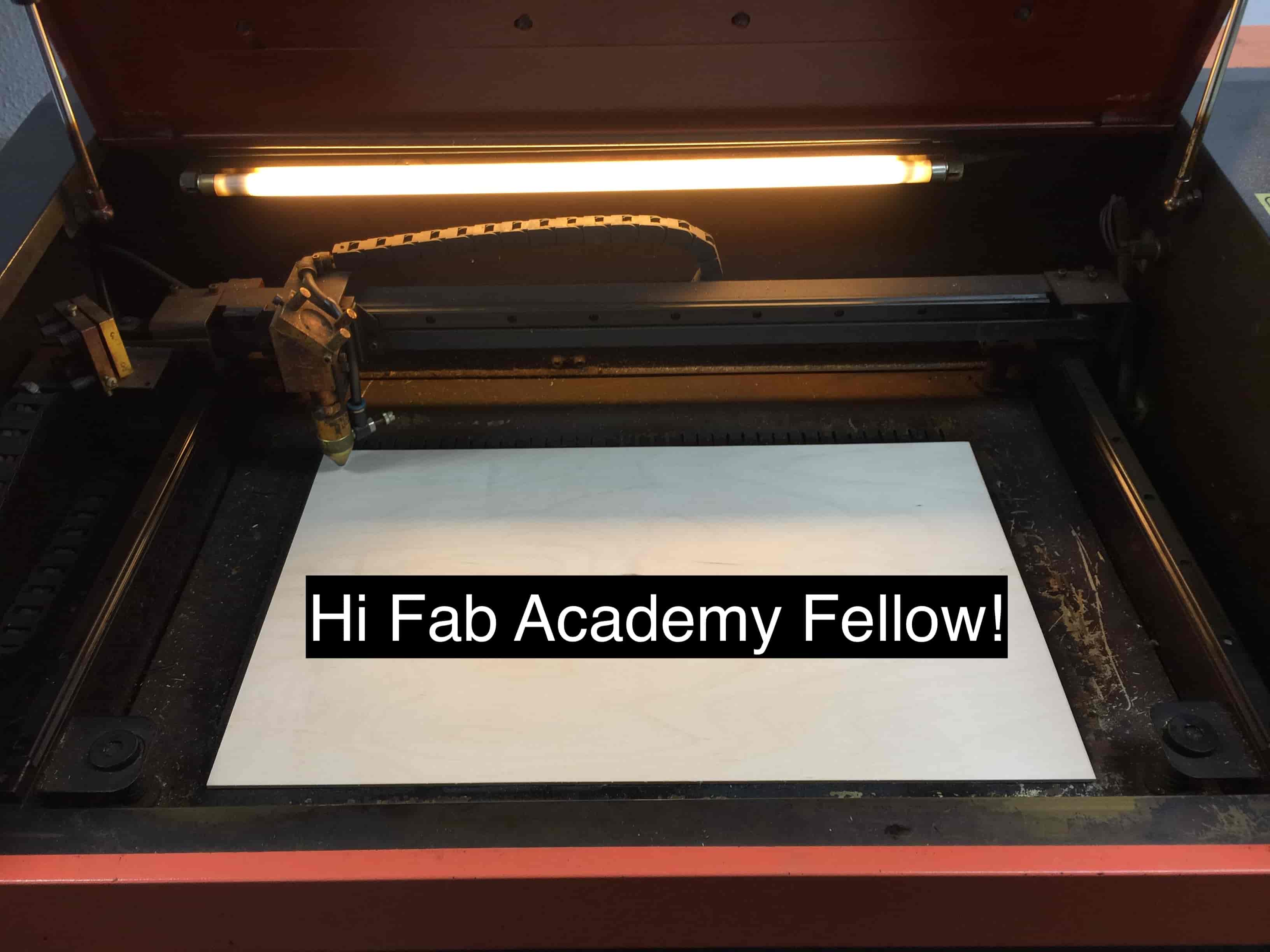
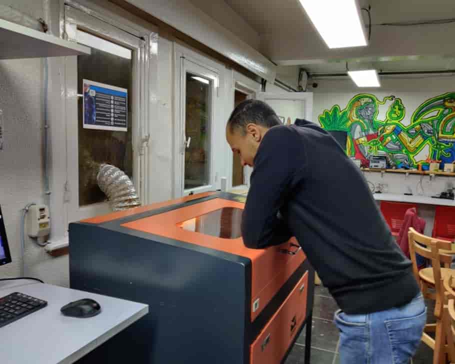
This week I was very excited, We finally gonna hit the ground and use the machines. I with my fellows We started with the group assignment right away after our local session, we were so excited to get our hands dirty!
In the group assignment, we managed to cover these points characterizing Machine focus, Power and speed, joints clearance, and the Kerf calculation.
characterizing Machine focus
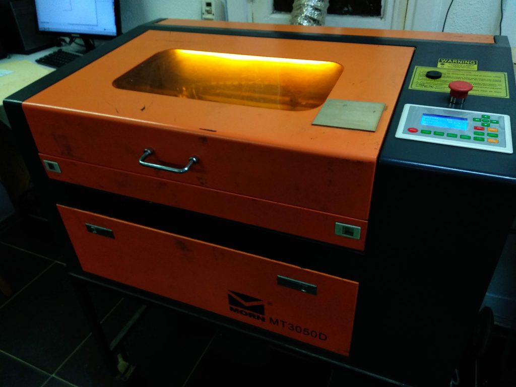
Before diving in any machine characterizing lemme introduce our Fab Lab baby MORN MT3050D. It's a 50/60 Watts CO2 laser machine with a working area 50*30cm.
Before using any laser cutter machine, the most important thing to check is the laser lens focus. Without a proper laser lens focus, you will not get clean cuts and engraving at the optimal performance.
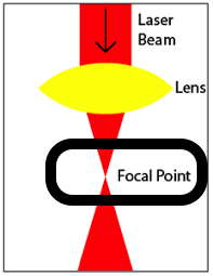
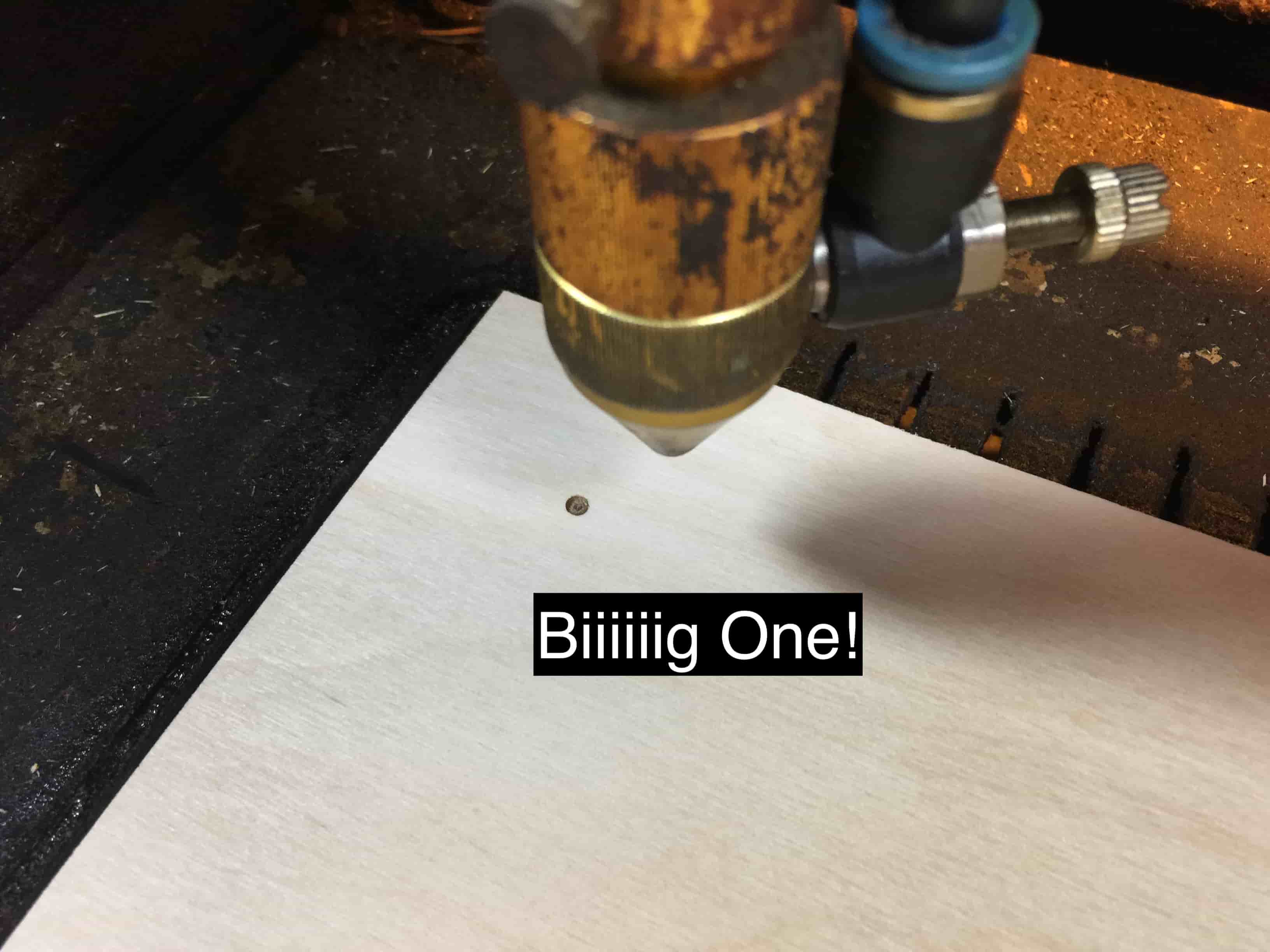
Look at that image, we need to adjust the distance between the machine laser head and the bed working area(work) until we reach the smallest laser dot(focal dot). This is the point!
Here in Fab Lab Egypt, we have a great team they have already set the machine laser lens focus so when anyone uses the machine will find it ready to go. But to be honest, I love to get my hands dirty with this stuff. So, I messed the machine bed level to make the laser focus lens out of focus. So, I can start the process from the beginning to learn how to do that lens focus thing alone without calling Abulnaga every time I use the machine :D
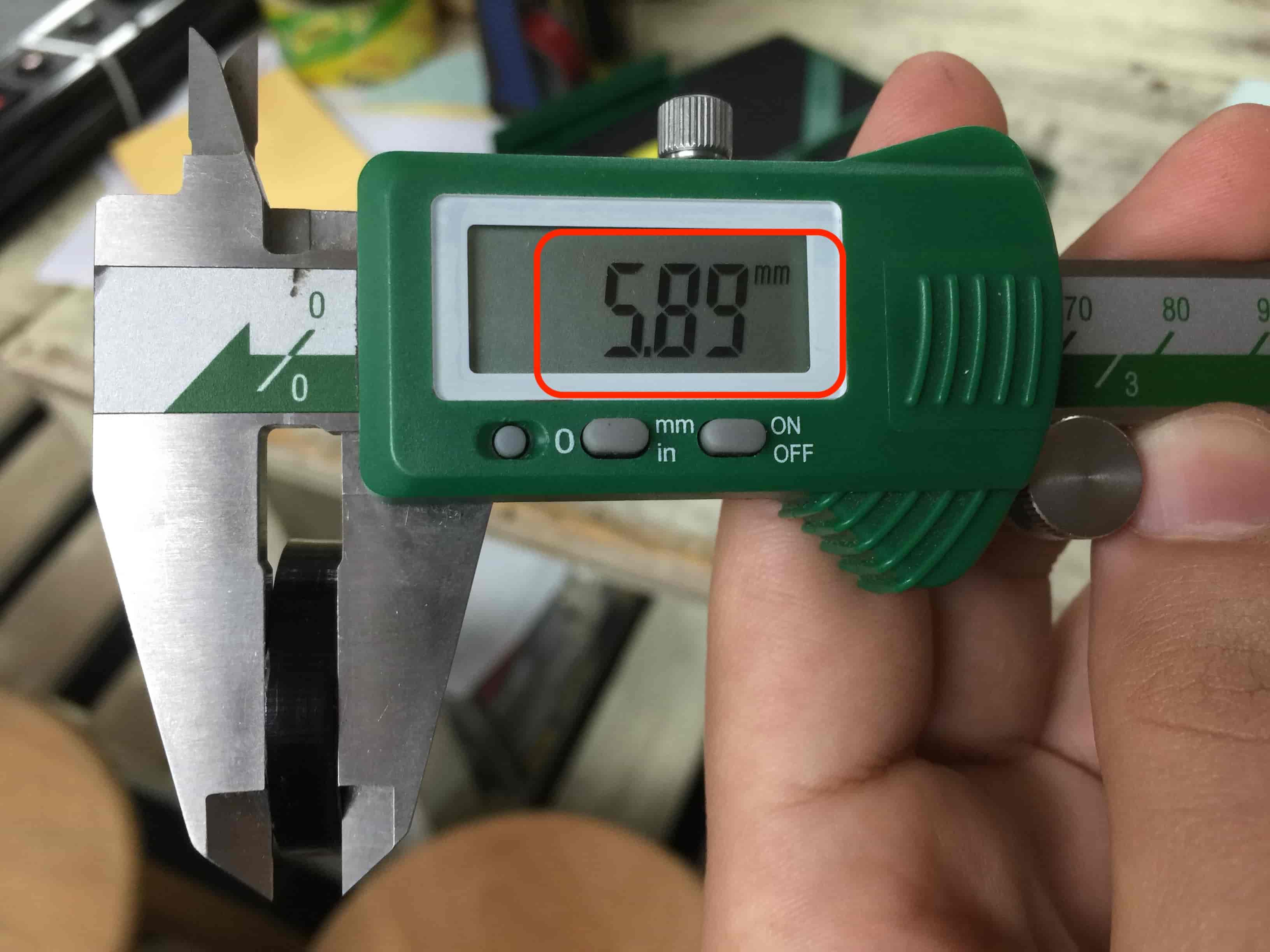
I put a plywood sheet with a thickness of 3mm to make some testing on it.
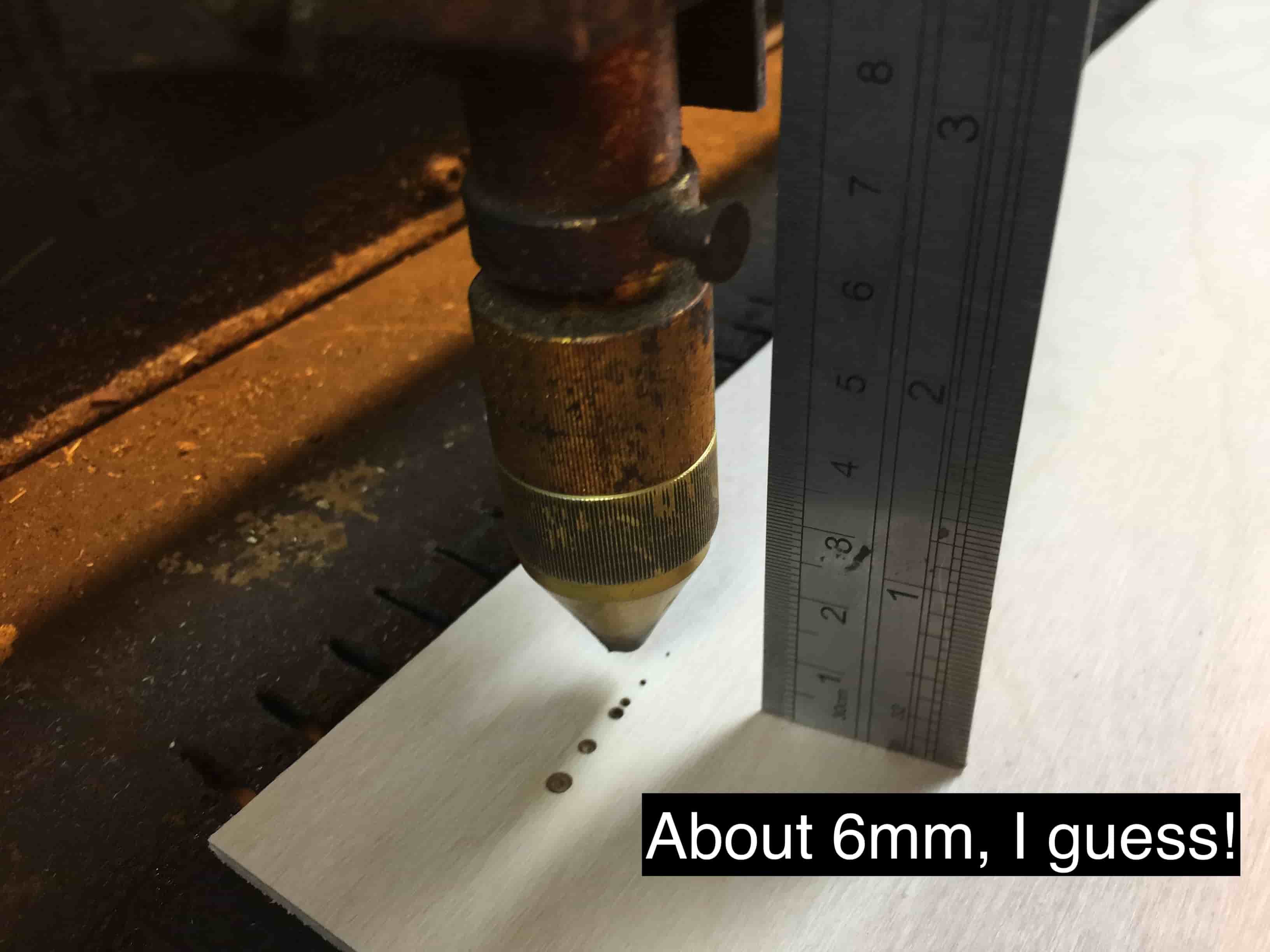
Then I started to trigger some laser pulses while I’m moving up the machine bed until I reached the smallest laser dot. This is the focal point we need.
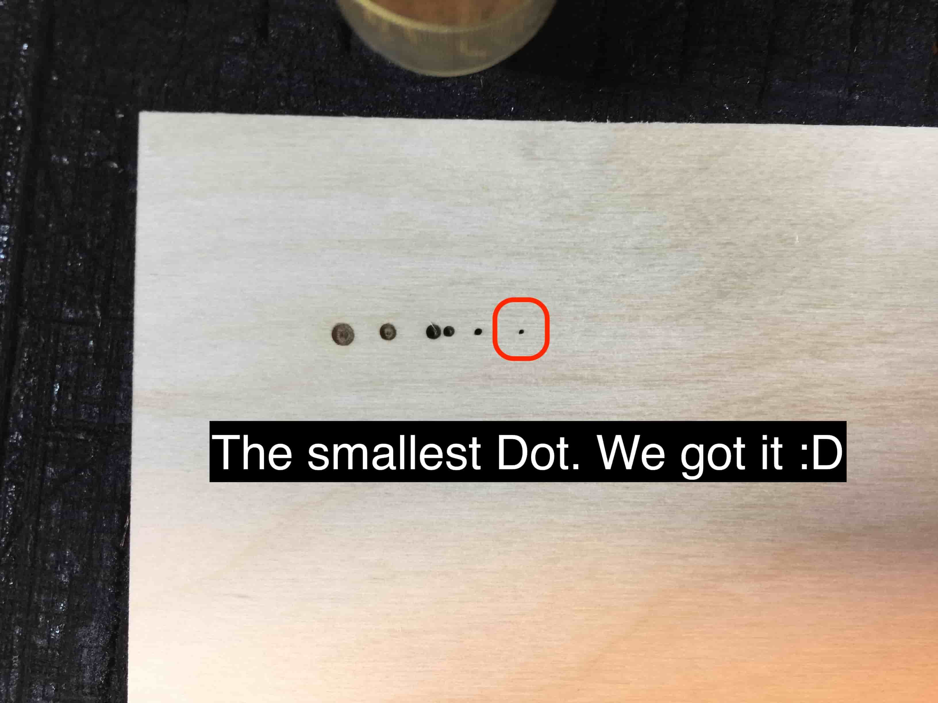
Now, it’s time to measure the distance between the laser head and the working place(work). The result is 6mm.
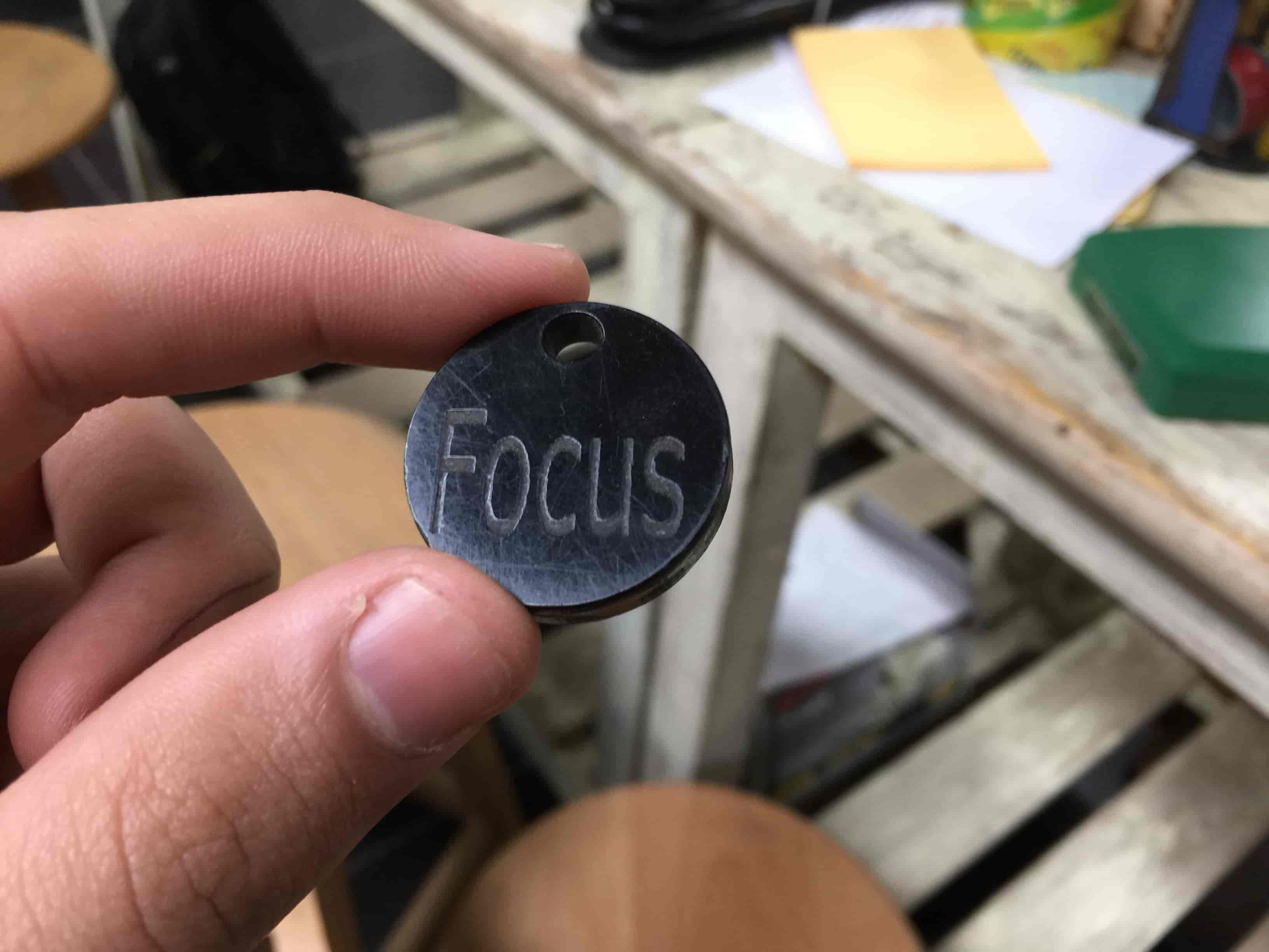
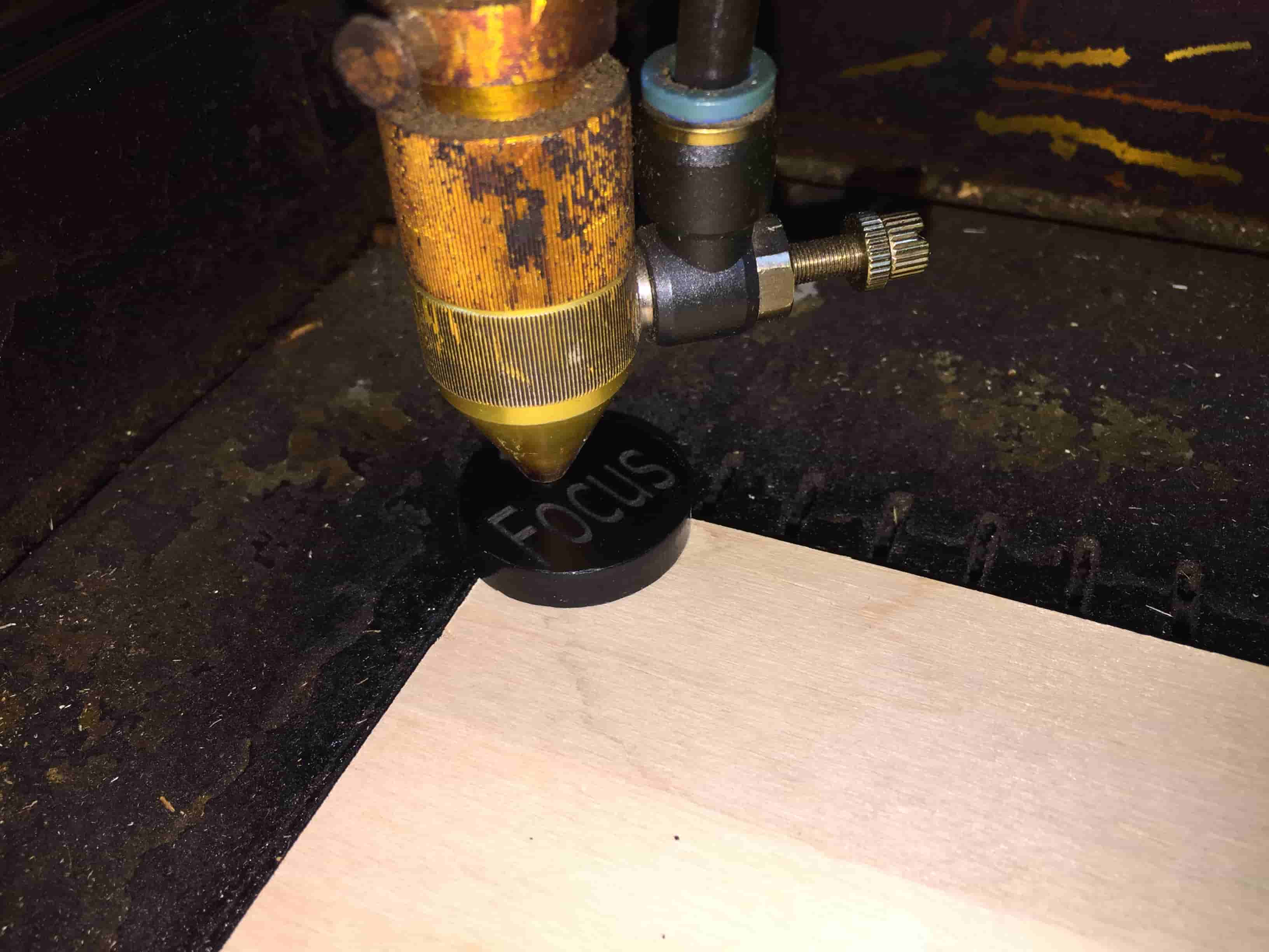
To make things easier, We at Fab Lab Egypt we have a thing called Focus coin, just level up the bed until it touches that coin and that's it!
characterizing Machine Power&Speed
Now, after we set the laser cutter machine focus. It’s time for messing with the machine cutting and engraving power and speed.
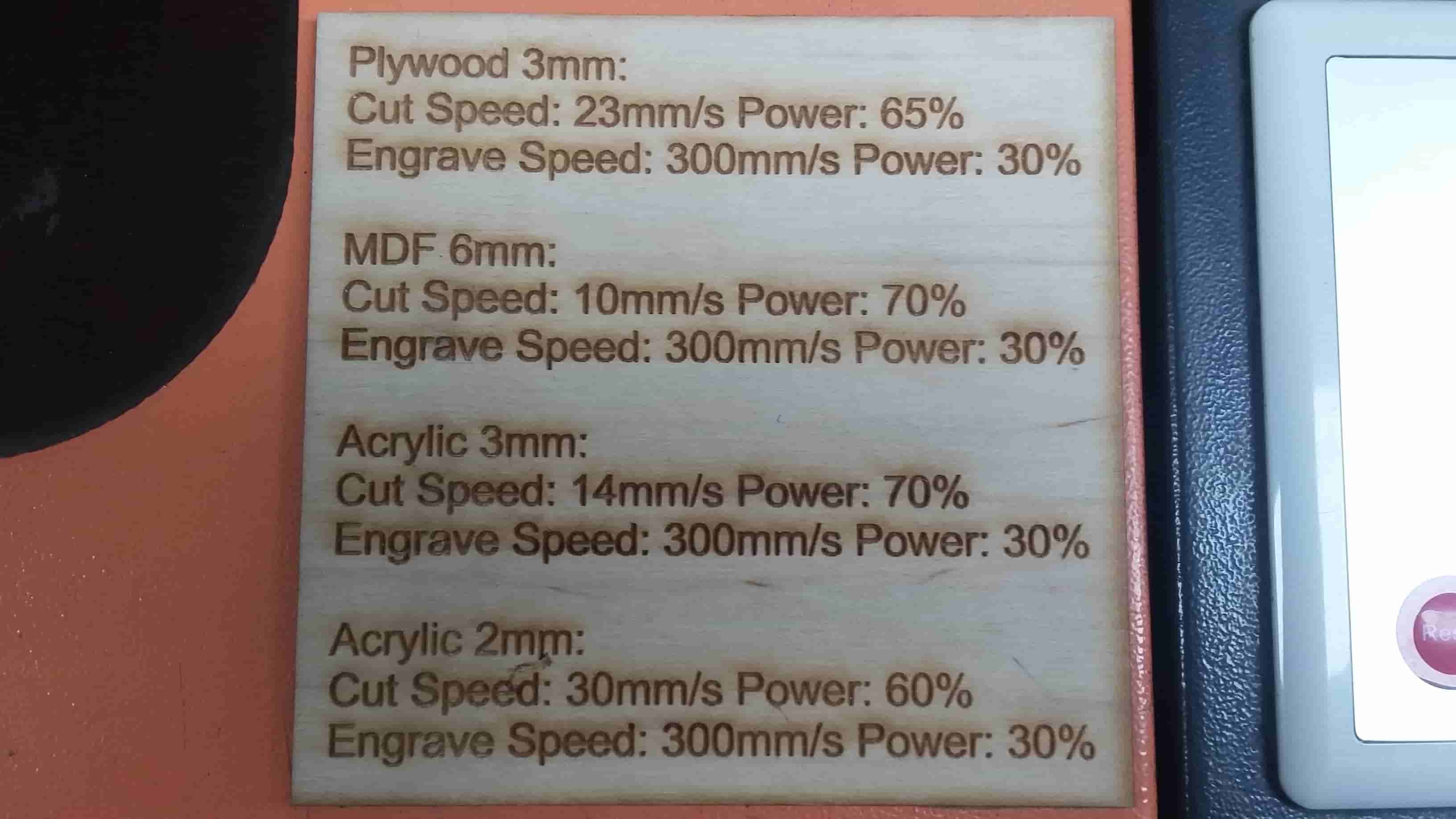
As I stated before, the Fab Lab Egypt technical team is great! They are putting a sign on the laser cutter machine telling the cutting/engraving power and speed for different materials and different thicknesses. So, you don’t have to do some testing to figure it out by yourself every time you use the machine.
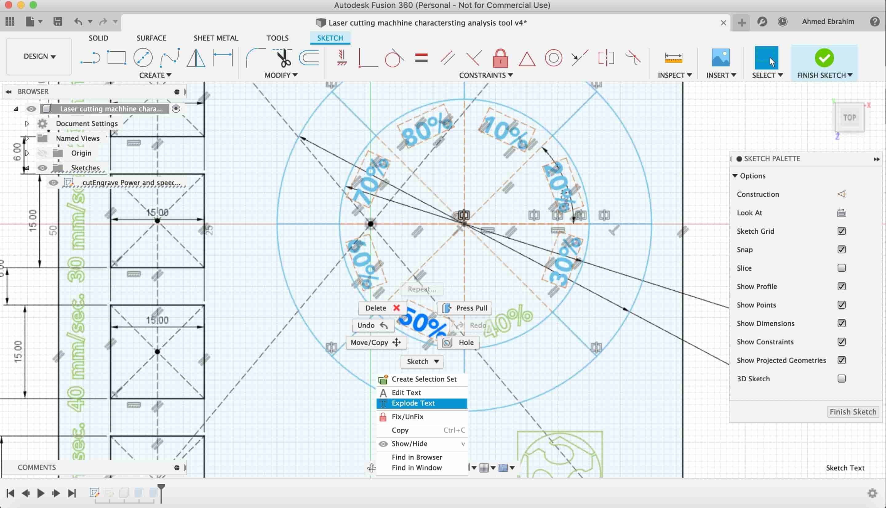
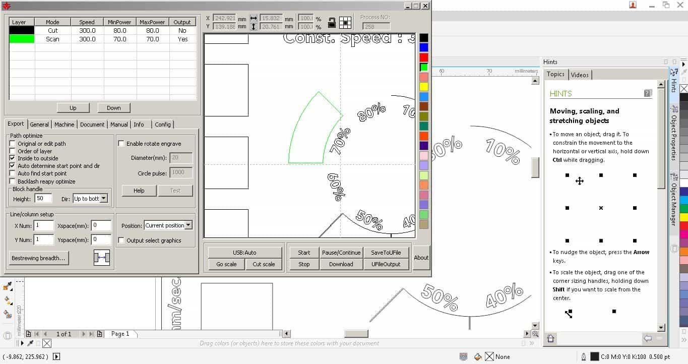
But you know, I like to try it by myself. I designed a tool to help me in testing some different cutting/engraving speed and power values to see at which value we will get the most clean-cut/engrave. I used Autodesk Fusion360 to design this part.
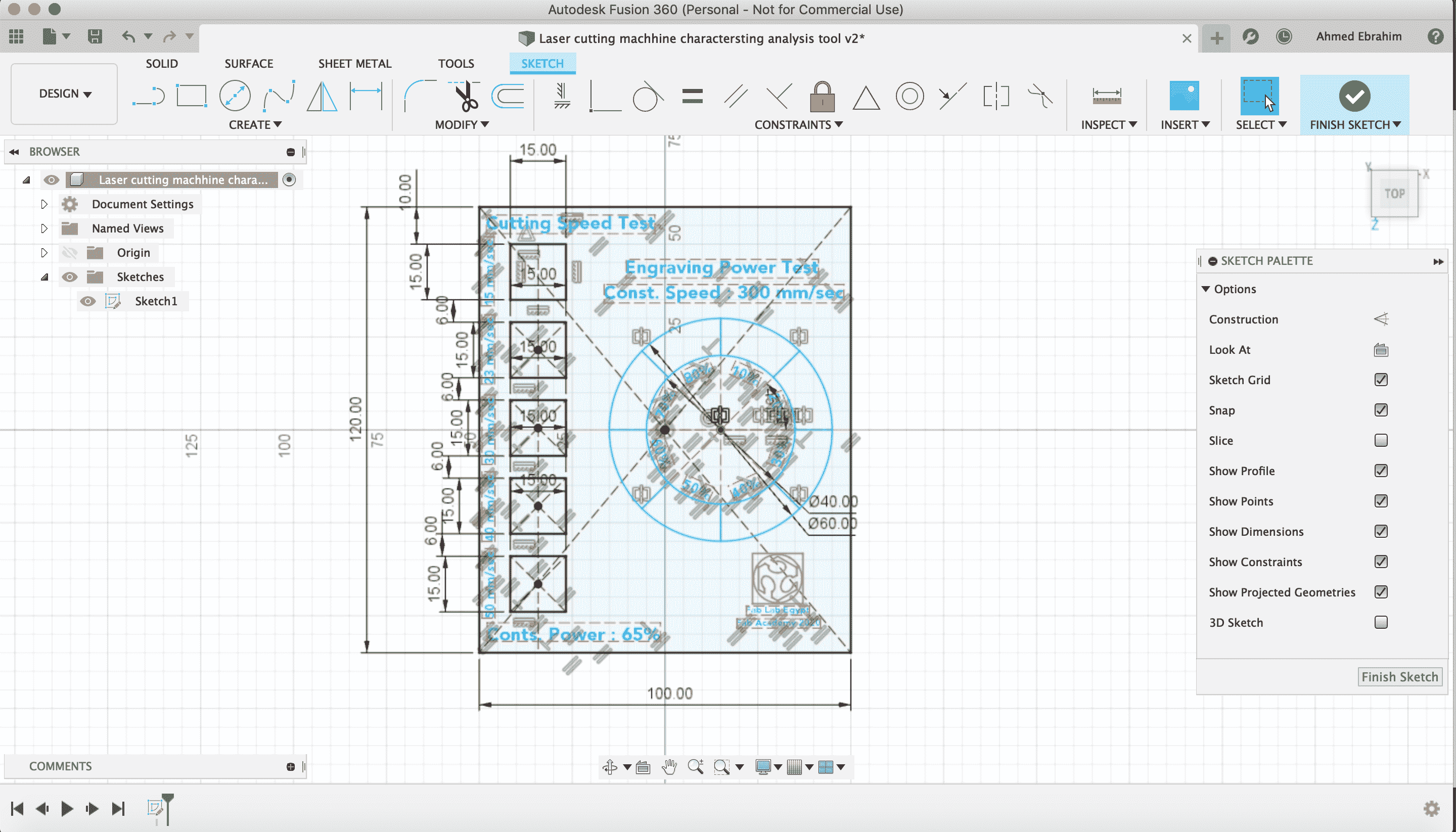
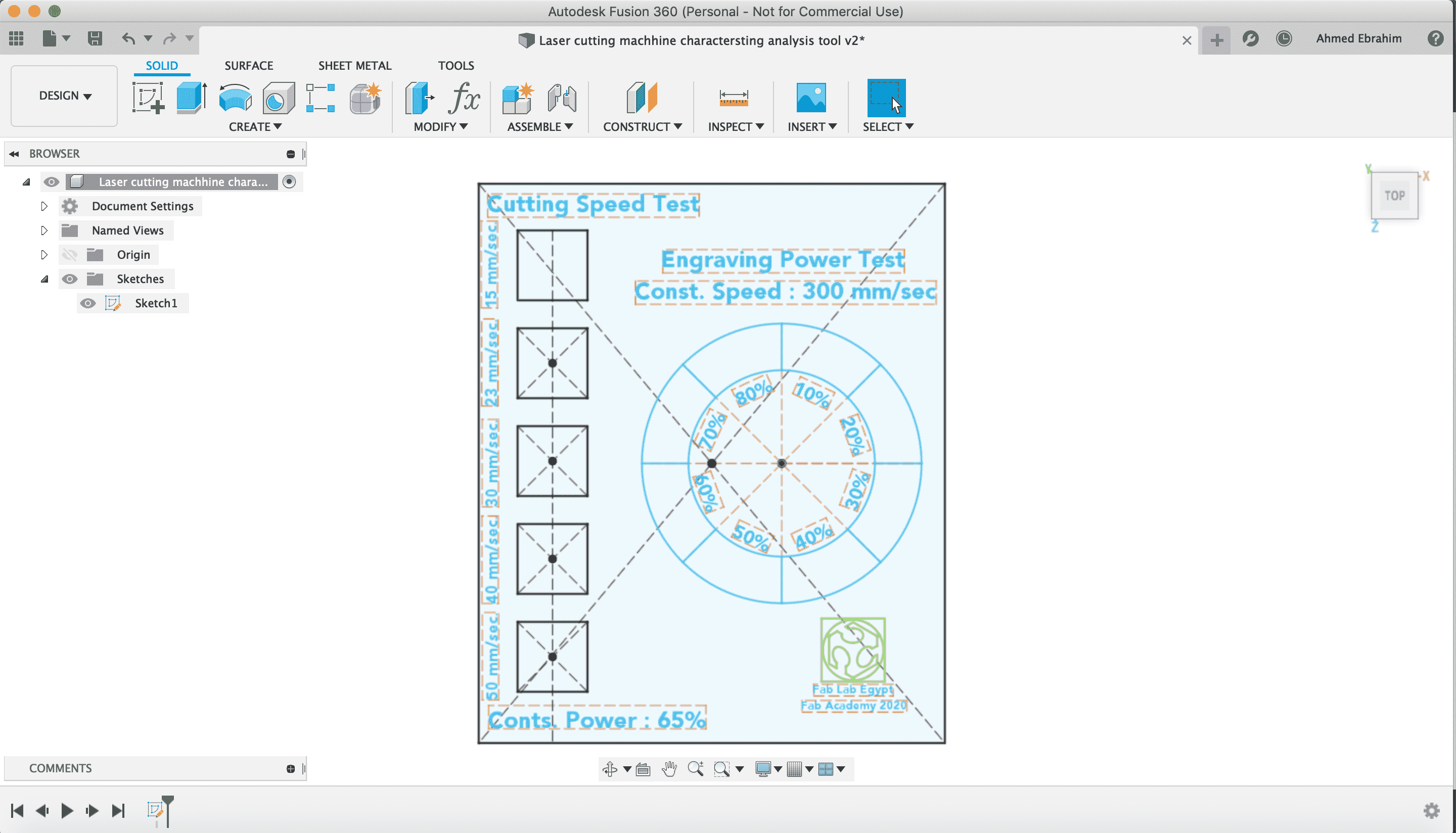
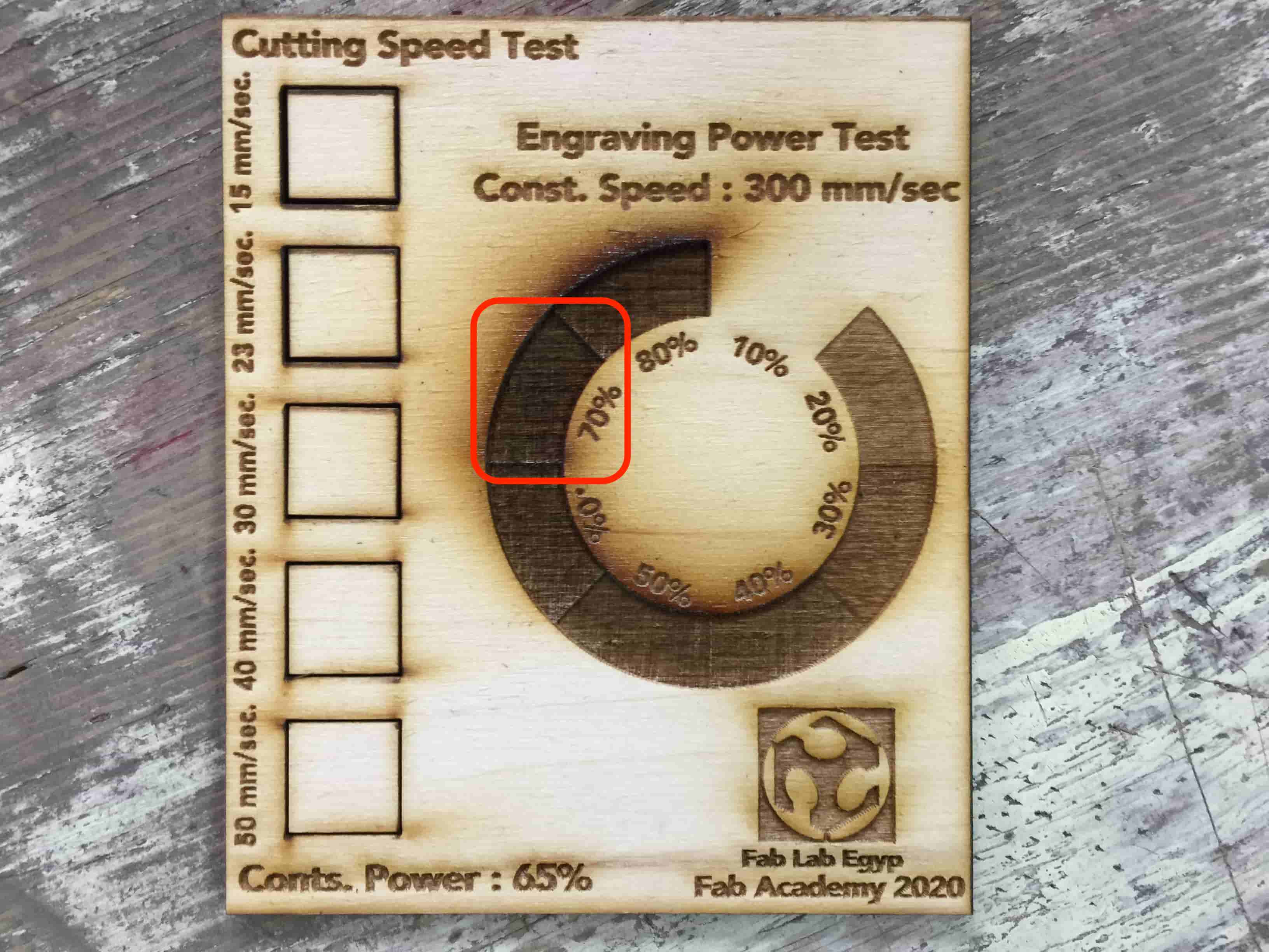
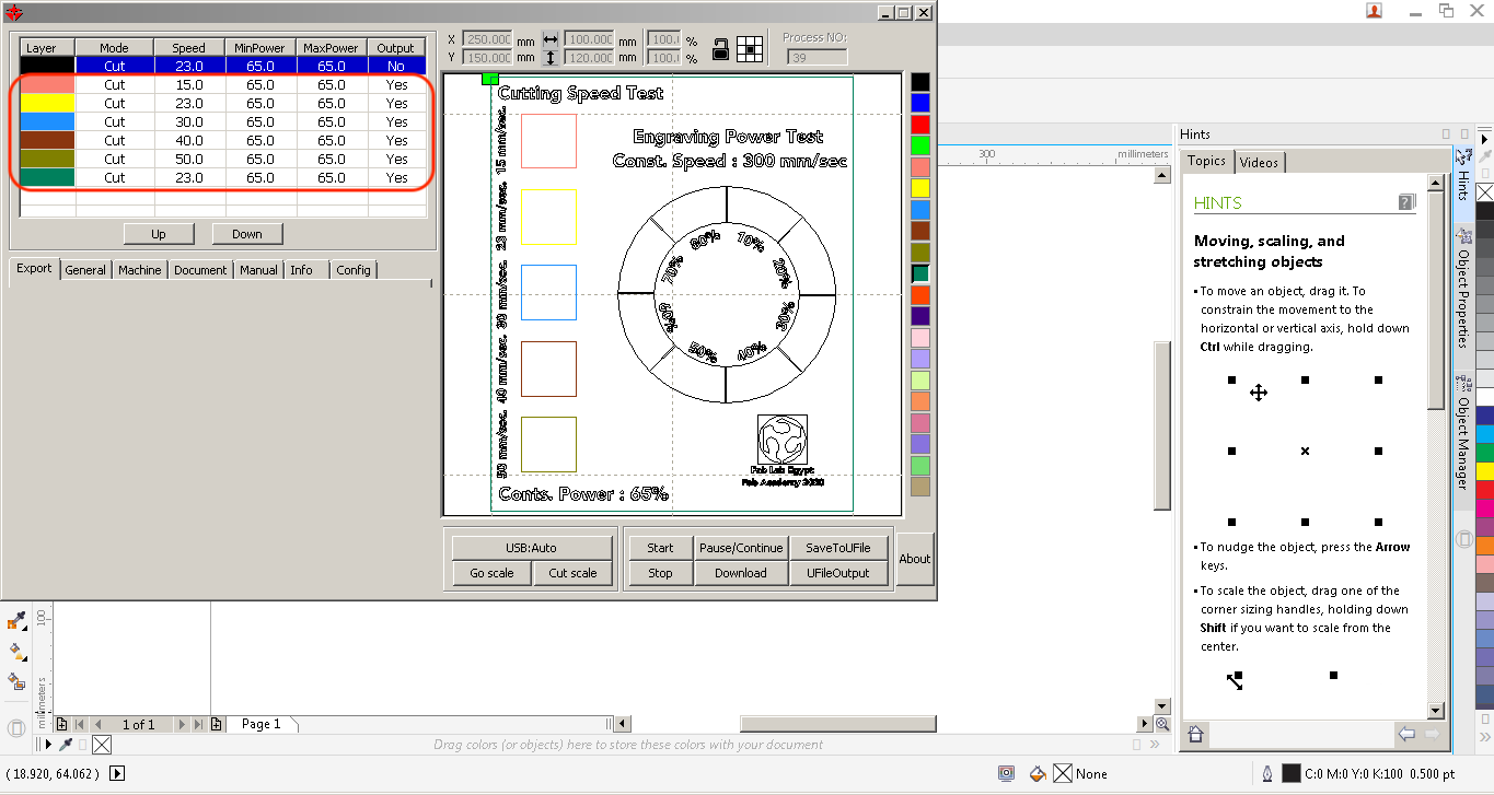
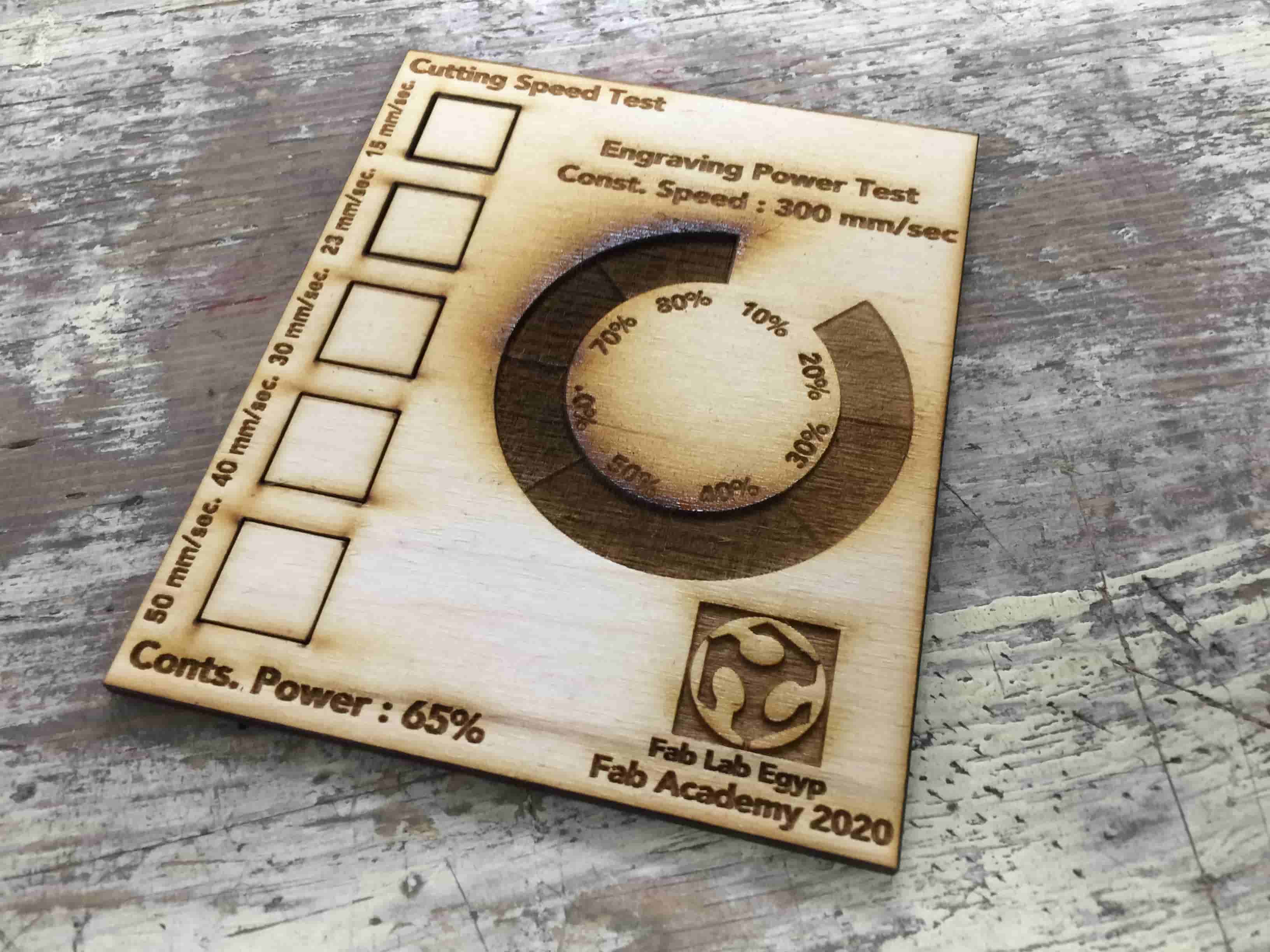
I drew a big rectangle with dimensions 100*120mm. This rectangle contains five small 15*15mm squares. The distance between each small square is 6mm. Each small square is set to a certain cutting speed that starts from 15mm/sec. And increases for every next square Up to 50mm/sec With a constant cutting power 65% for all the small squares.
And for engraving, I drew a 60mm diameter circle and a 40mm diameter circle inside the first one. That circle is divided into 8 sections. Each section will be engraved at different power starts from 10% up to 80%. But, all the sections have the same engraving speed which is 300mm/sec.
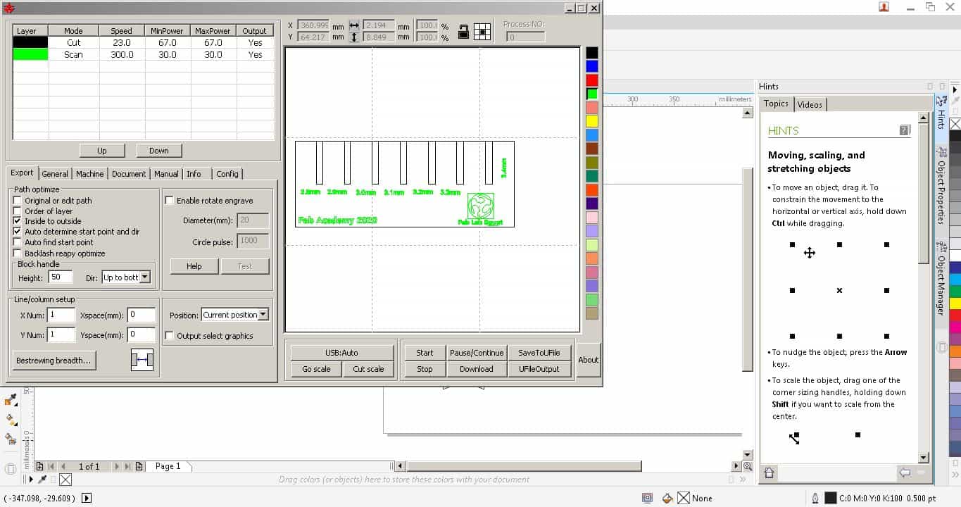
I exported the Sketch DXF and Imported it into CorelDraw to send it to the laser cutter machine. Furst, I created a new document on Corel Draw with the Laser cutter machine working area whhich is 500mm*300mm
There is something weird man! Where's the text which I put in my fusion design? After doing some search about "why text is not appearing in a fusion360 exported DXF File". I found that in order to the text appear in the DXF exported file, I must select each text in my fusion360 sketch and make "Explode text" to each one.
I return back to my fusion project and edited that then I exported the DXF file again.
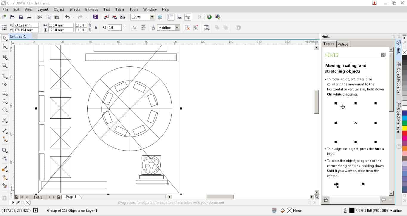
I imported the DXF file again to CorelDraw and not it's working fine.
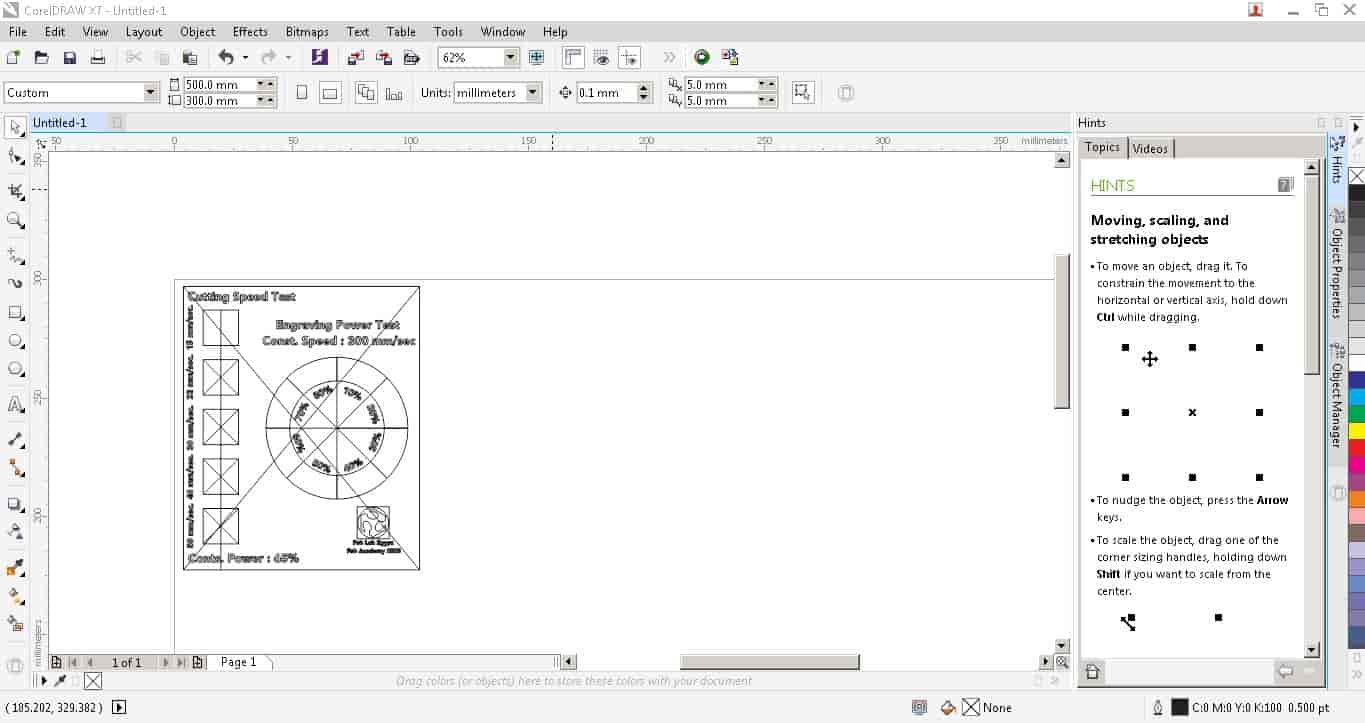
There's a lot of work to do with this part on CorelDraw, First we need to delete all the construction lines. Second, I engraved all the text only at one time.
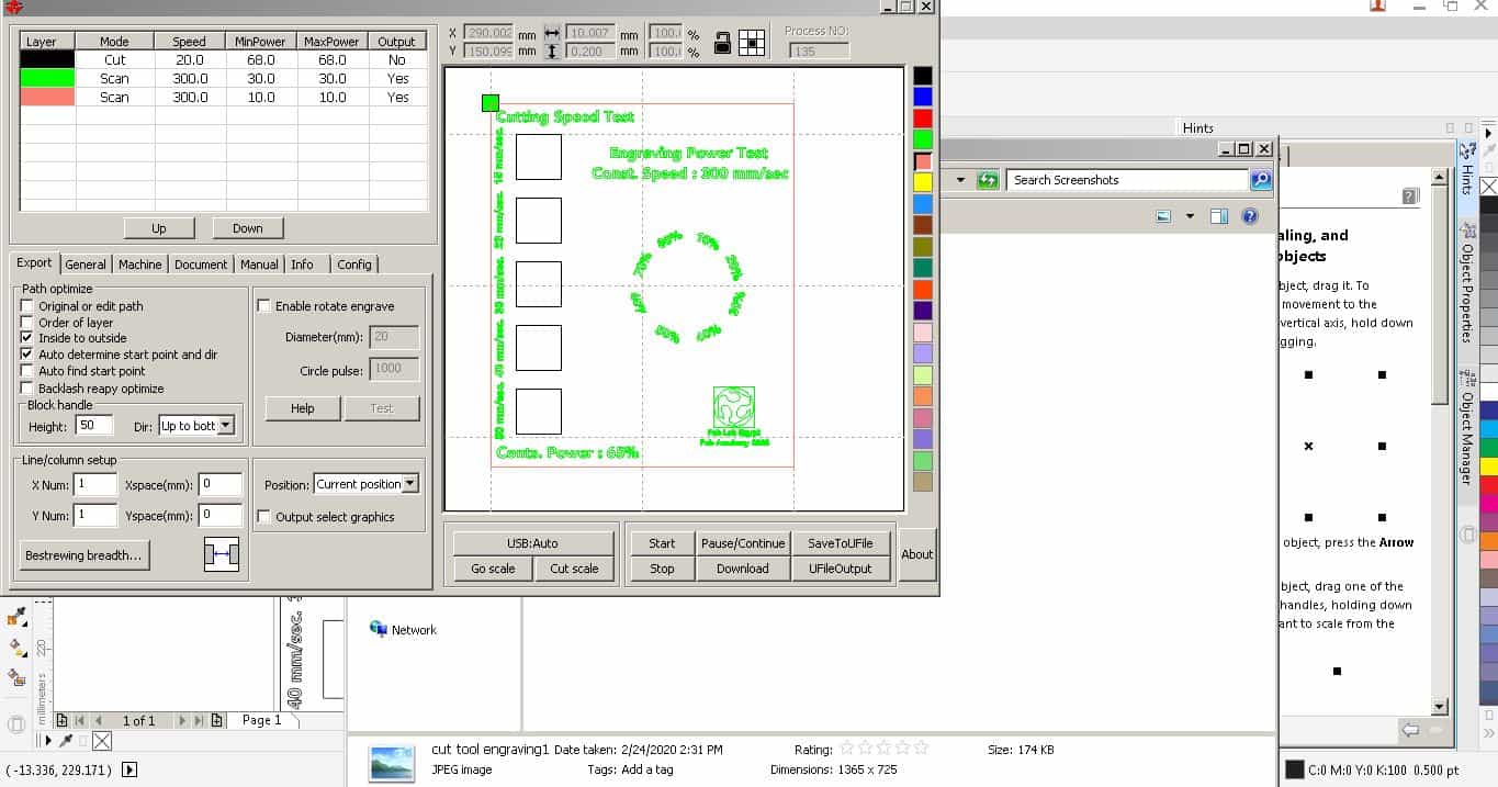
Then, We need to engrave each section alone. I tried to engrave all of them in the same time but It failed.
After finishing this part, we need to start the next engrave section and so on.
After that cutting all the sqaures with different speeds, also cutting the outline. That's the last step.
- I guess the machine clean cut is at Speed 23mm/sec. And power 70%.
- The clean engrave is at Speed 300mm/sec. And power 30%.
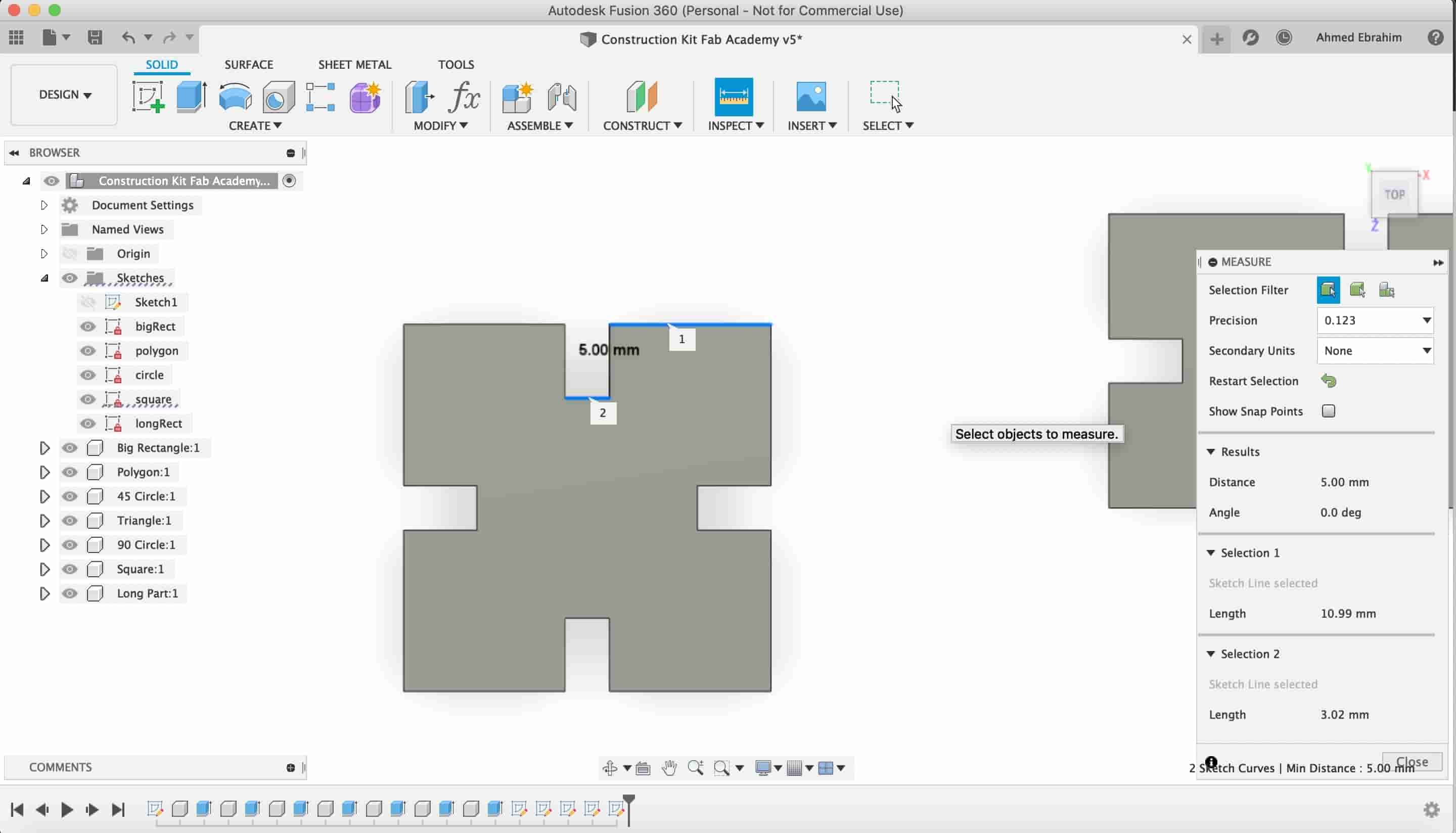
Now, it’s the time for some machine Kerf calculation. I drew a simple square on CorelDraw with dimensions 15*15mm and cut it at speed 23mm/sec. And power 65%.
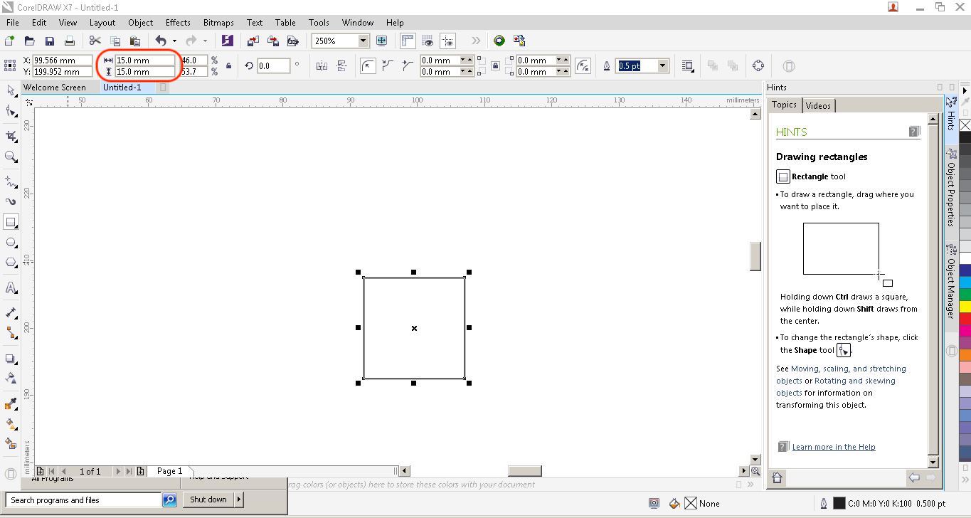
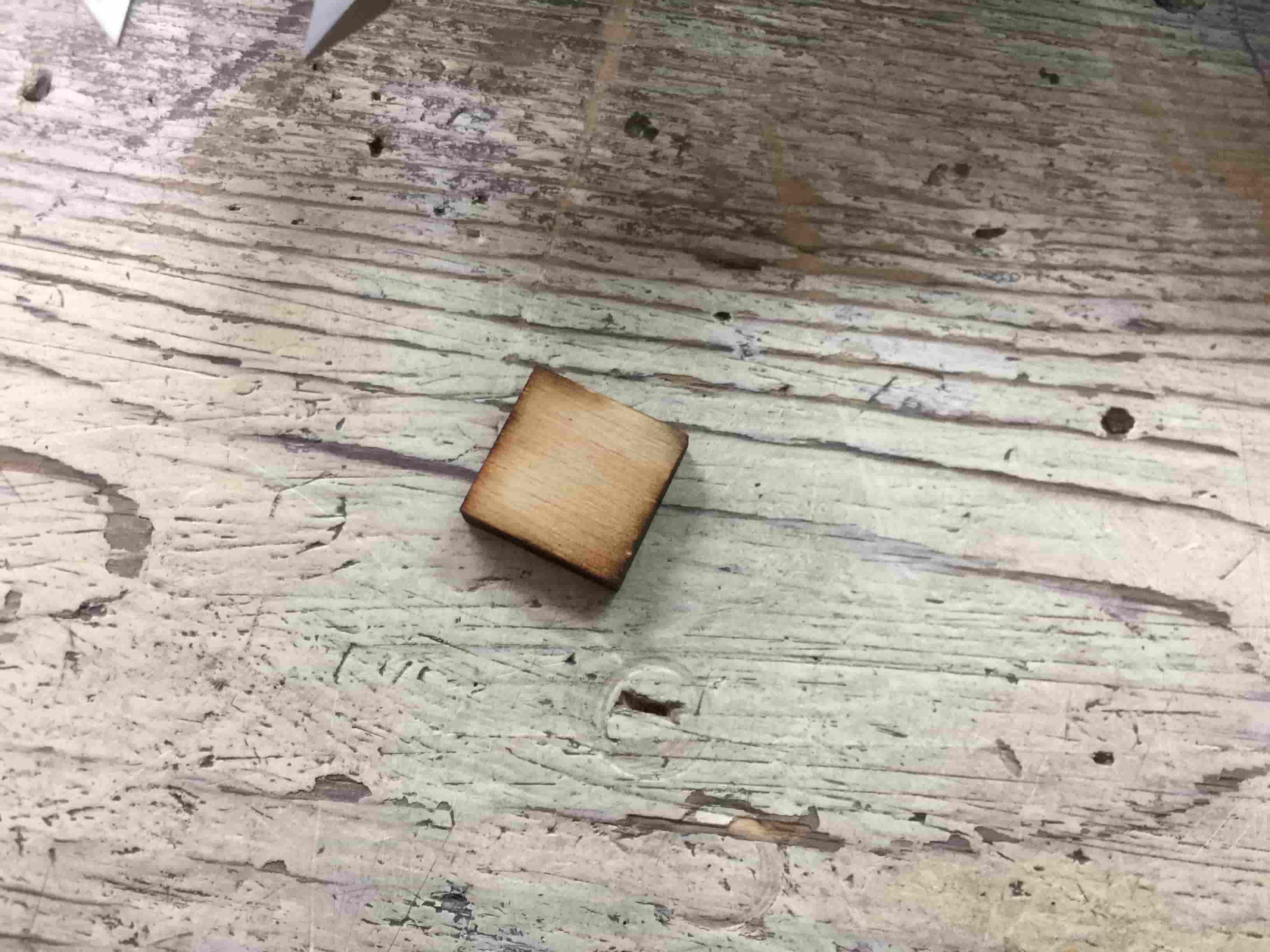
The actual square dimensions after cutting are 14.8*14.8mm. That
means the machine Kerf equals to
15mm (Design dimensions) - 14.8 (Actual
dimensions) = 0.2 (Kerf).
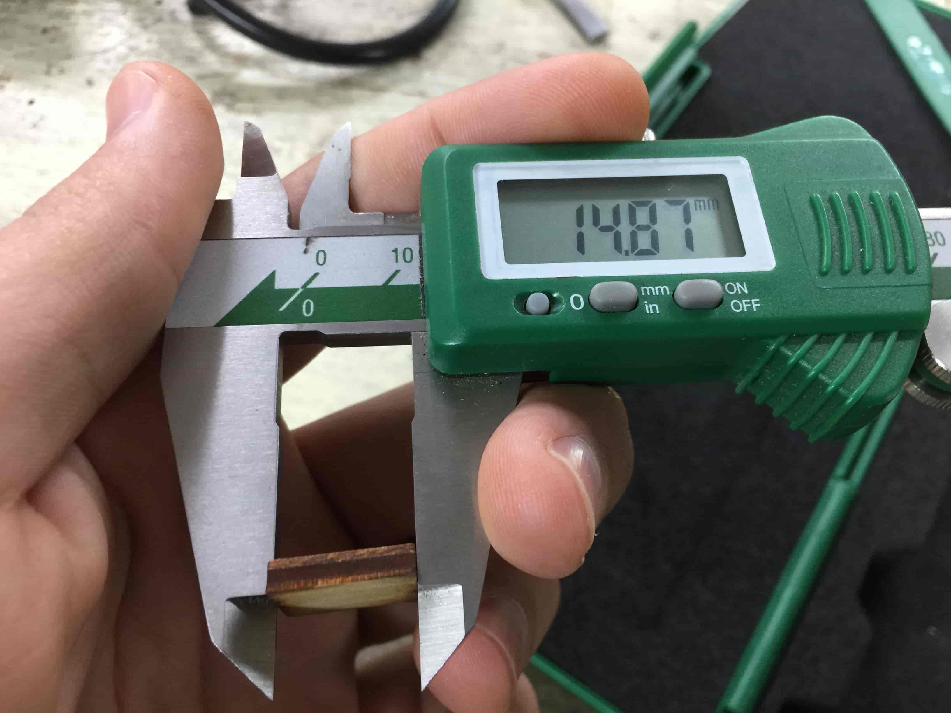
To make sure that the result is accurate I cut three more squares with the same dimensions 15*15mm, I measured them too and take the average of the 4 squares kerf. (0.12+0.15+0.13+0.13) / 4 = 0.132mm
Joints Clearance
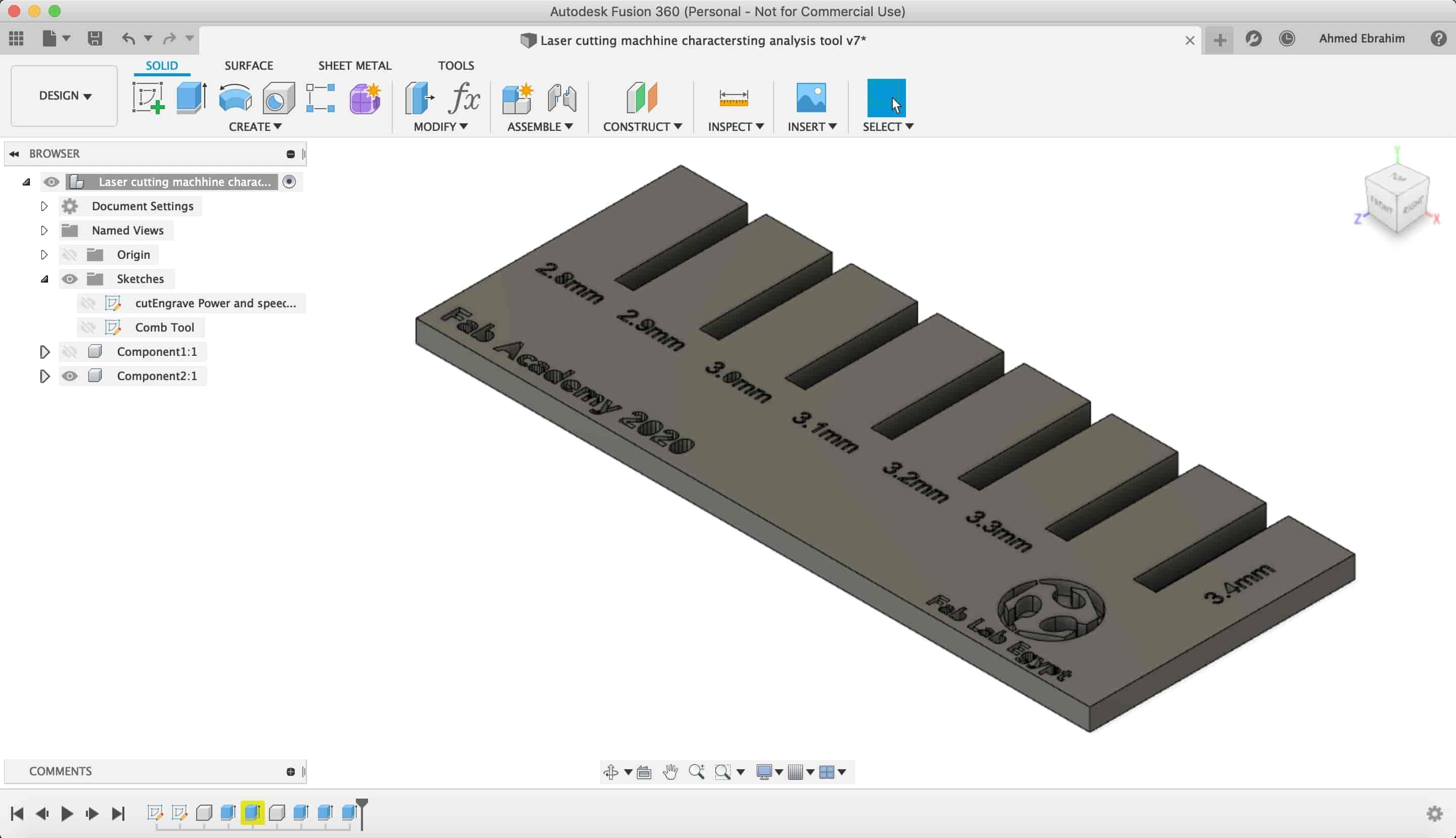
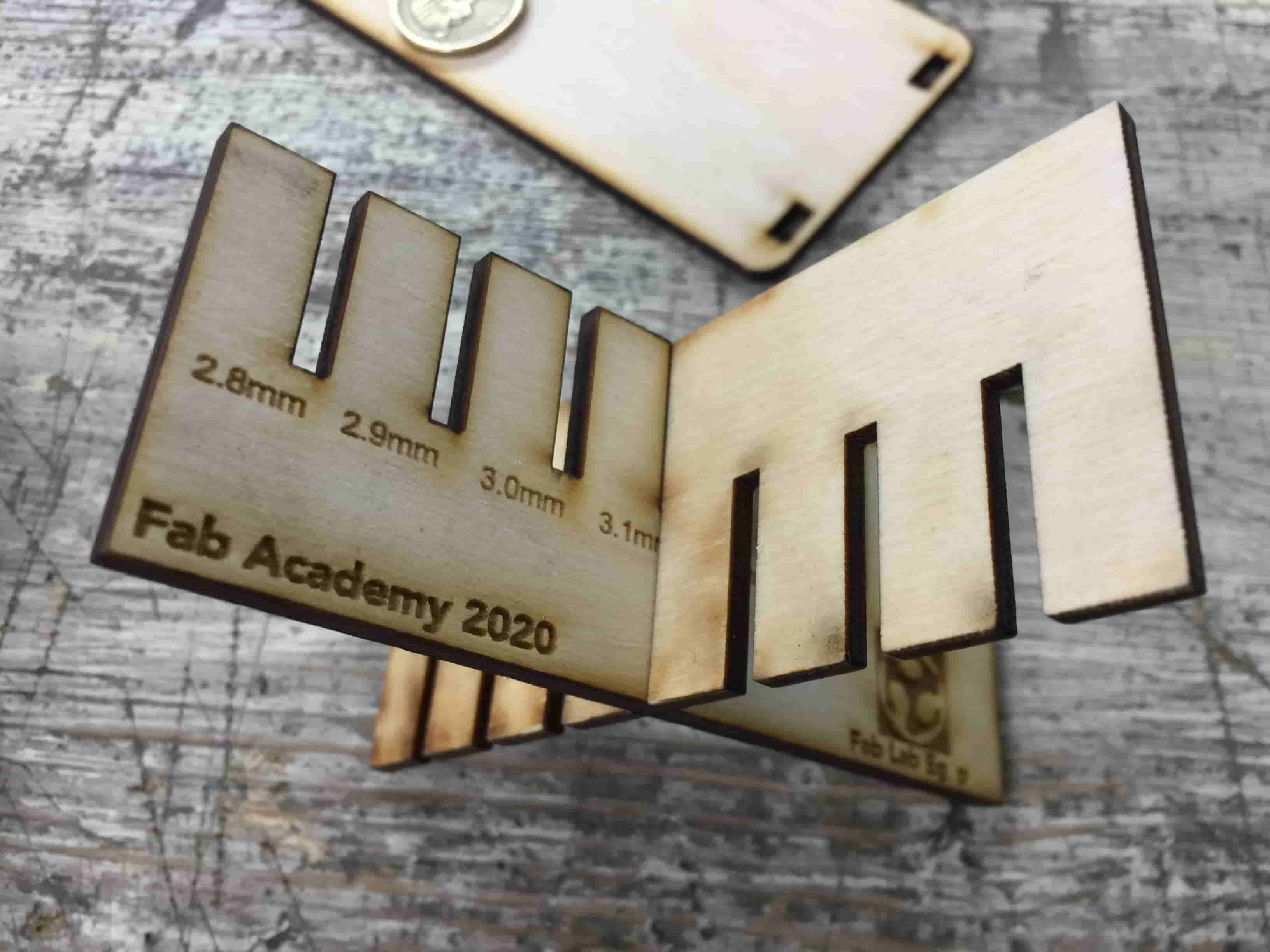
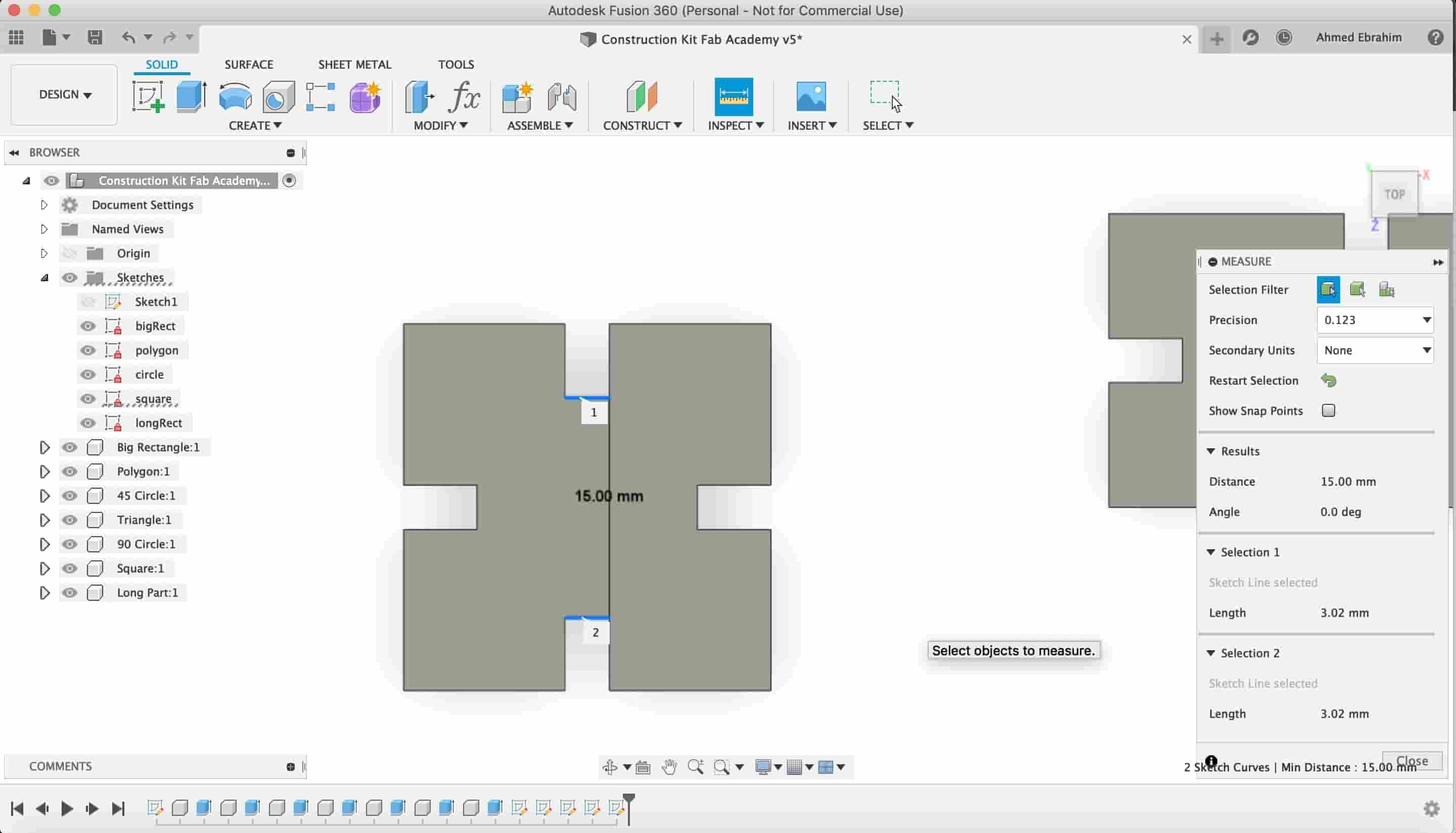
It’s time to try some joint fitting and clearance. I designed this tool to help me characterize the machine joints clearance. It’s the popular comb, a quick tool almost every laser cutter machine nerd uses it to test the joints fitting clearance.
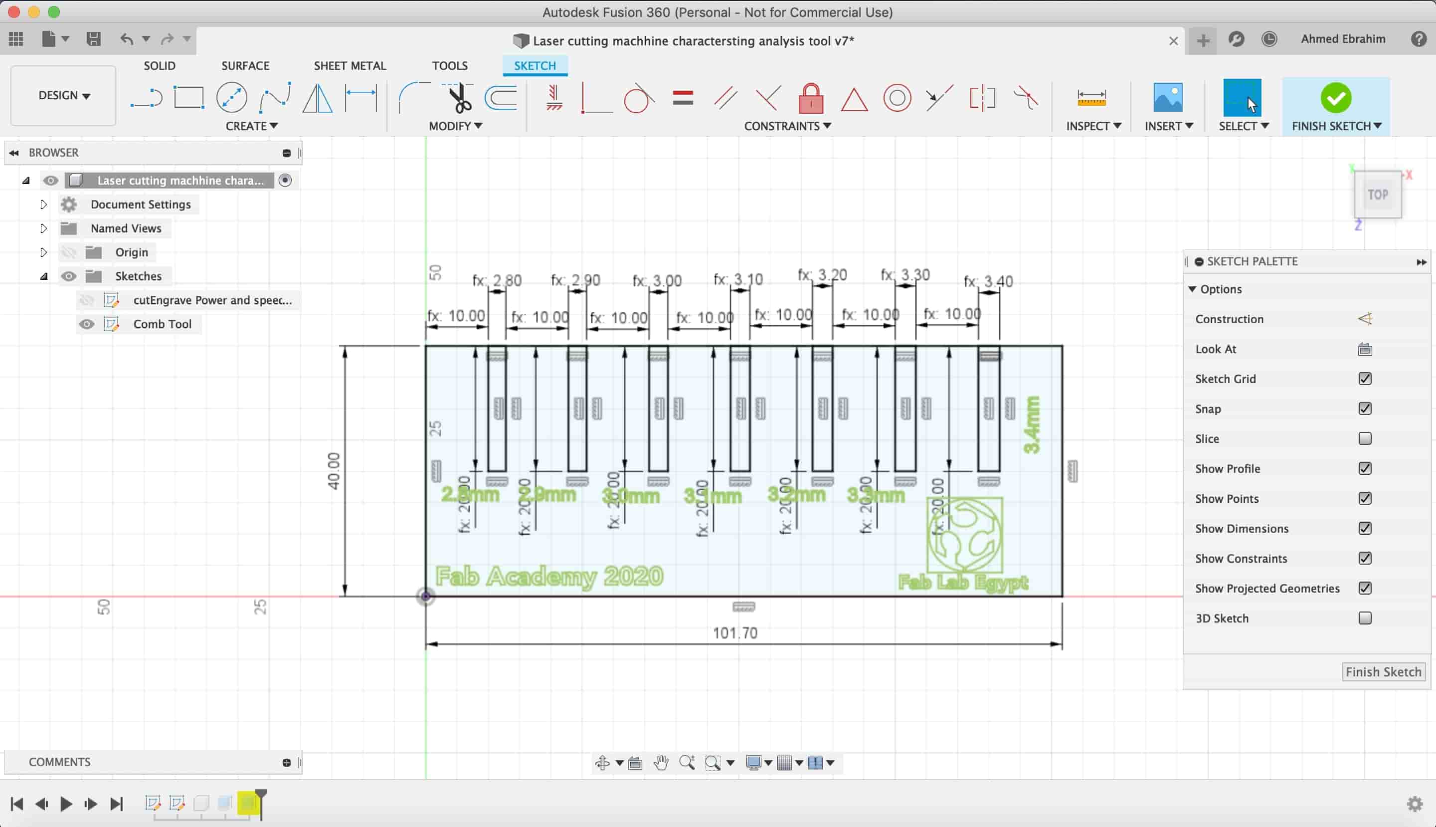
The comb is a series of slots ranging from 2.8mm to 3.5mm in 0.1mm increments.
After importing it into CorelDraw, and setting the cutting Power and speed to 65%, 23mm/sec. Respectively. And the engraving power and speed to 30%, 300mm/sec.
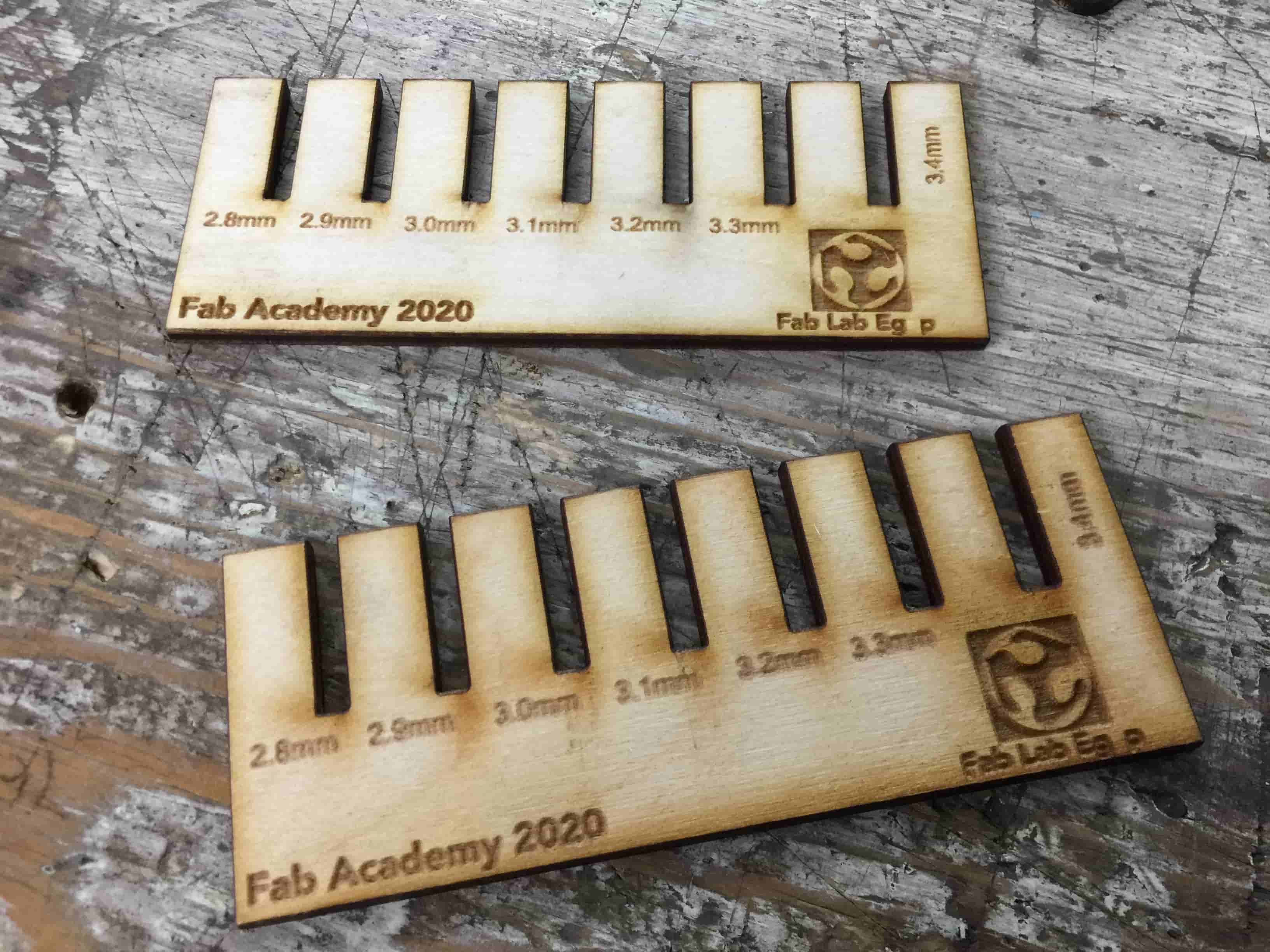
I found that the Joints is fitting very well at the 3mm Slots.
Laser Cutter Machine Characterizing Summary
| Cut | Engrave | |
|---|---|---|
| Plywood (3mm) | Power: 70%
Speed: 23mm/sec. |
Power: 30%
Speed: 300mm/sec. |
| Acrylic (3mm) | Power:70%
Speed: 14mm/sec. |
Power:30%
Speed: 300mm/sec. |
| Cardboard (2mm) | Power:25%
Speed: 45mm/sec. |
Engraving cardboard Data |
Laser Cutting Machine Templates Files Download
Construction Kit (Individual Assignment)
I will be honest with you Fab Academy fellow, I have never used parametric design before. But after a lot of Fusion360 tutorials and blogs, practicing and getting my hands dirty in multiple designs during this week, I’m becoming more comfortable with it. And I discovered that parametric design is not that hard and It saves you a lot of time later in the debugging and editing your design process.
From a programmer perspective, parametric design is like declaring some variables and assign some values to these variables, all these variables are connected together through mathematical equations, If one variable value changes, all the other variables will change too.
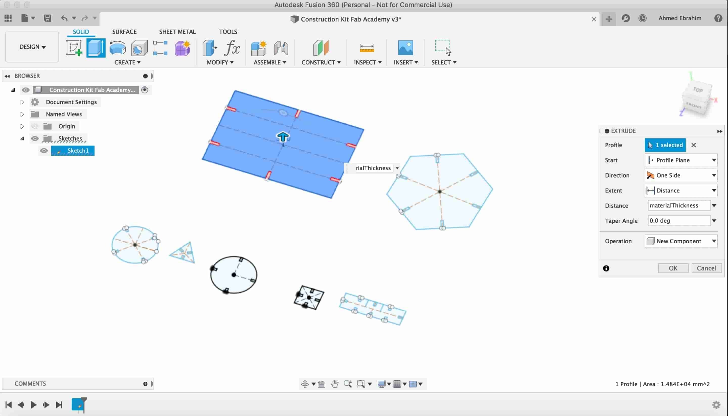
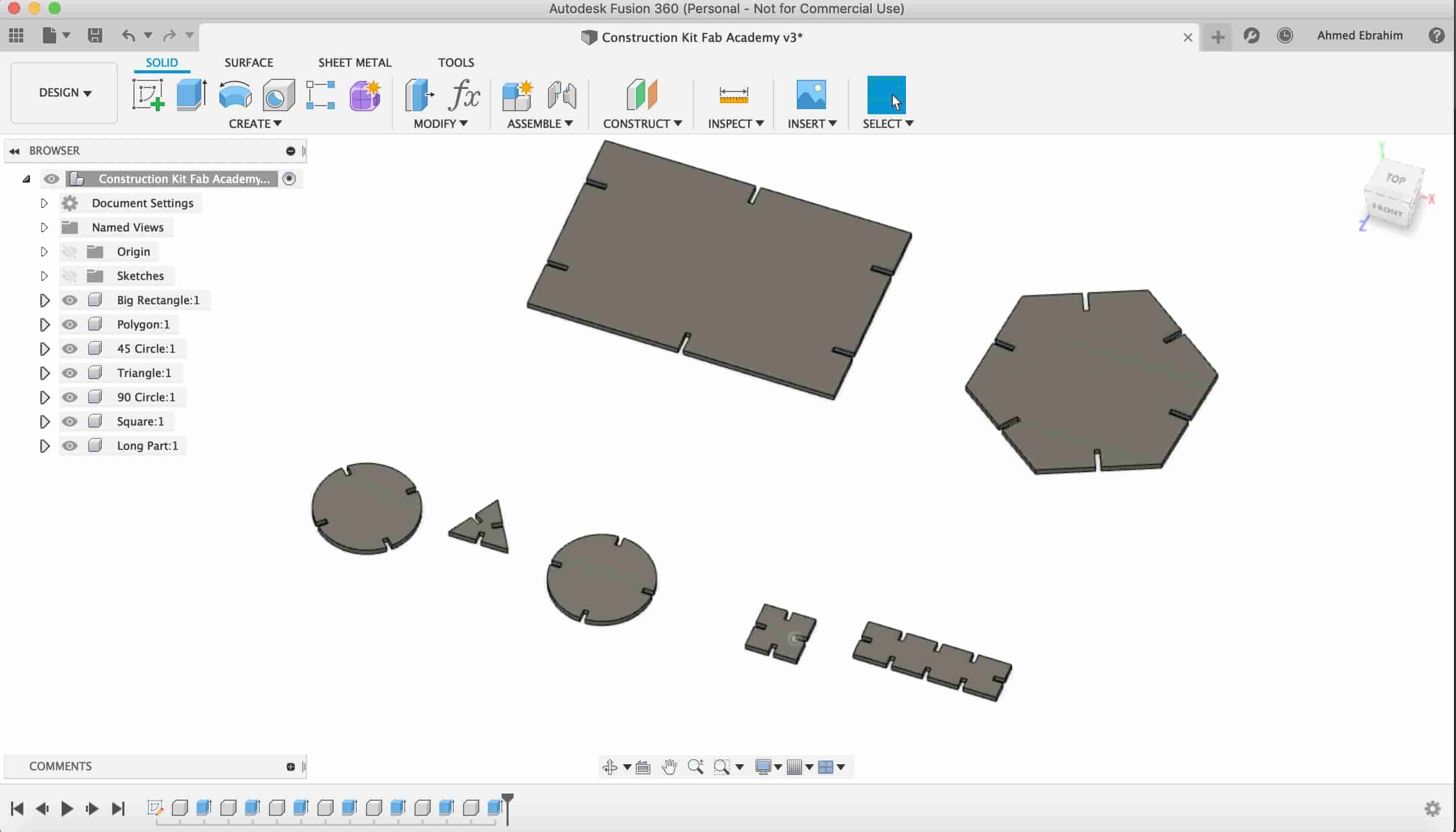
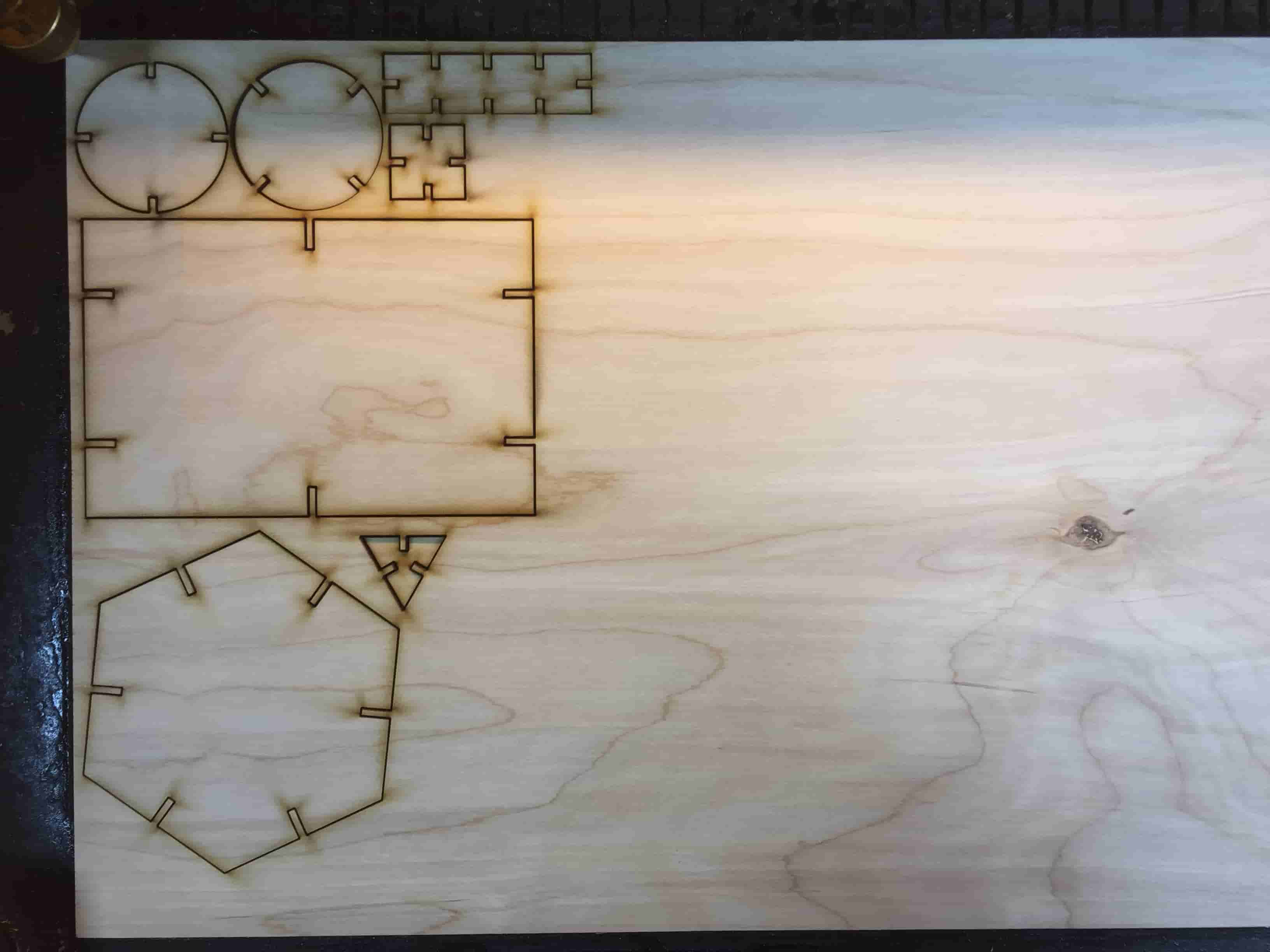
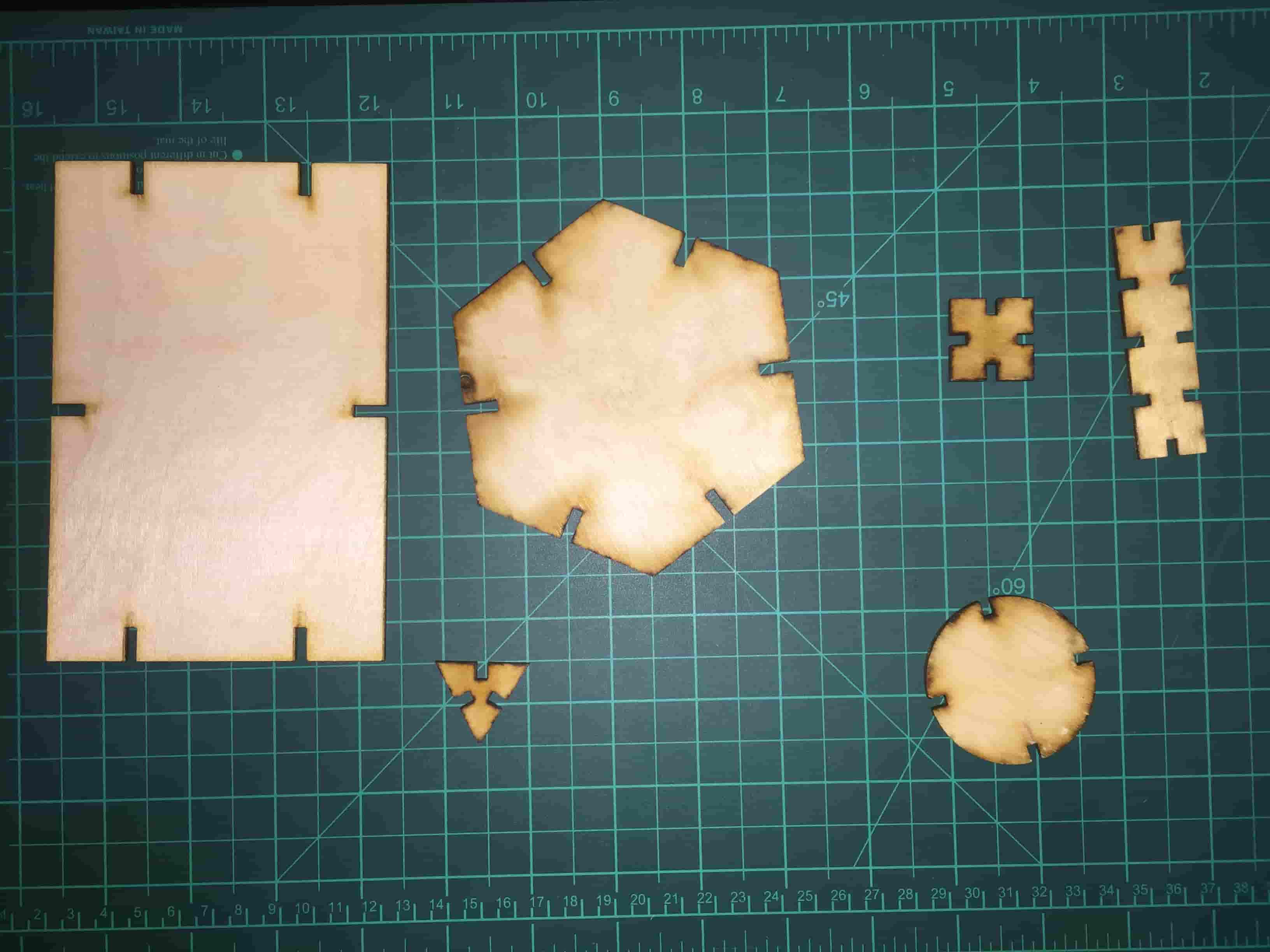
I decided to draw some basic geometrical shapes, these shapes have some slots in different positions so they can get connected together in a way or another. All the design is parametric, putting the material thickness and Kerf in mind.
I started drawing a circle with a diameter of 50mm. This circle has four fitting so it can get connected with the other shapes. The slot depth is 5mm. And the slot width is 2.6mm. These values are depending on the material thickness and the Kerf. so if you want to change that slot width you can change the Kerf and material thickness parameters.
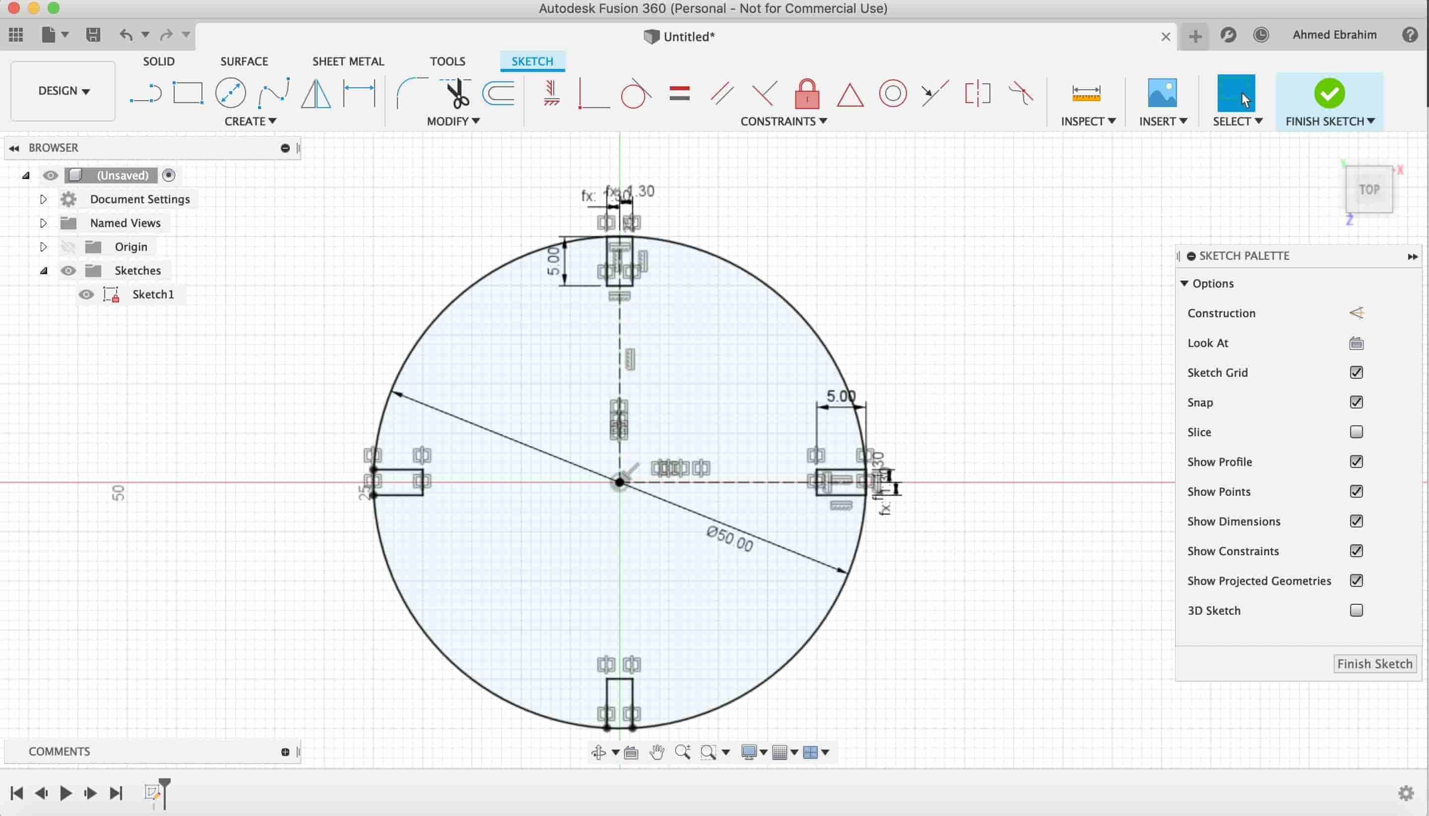
After finishing the circle shape, I started drawing on the same sketch a square shape 50*50mm with also four slots around its sides to connect it easily with the other shapes in any orientation.
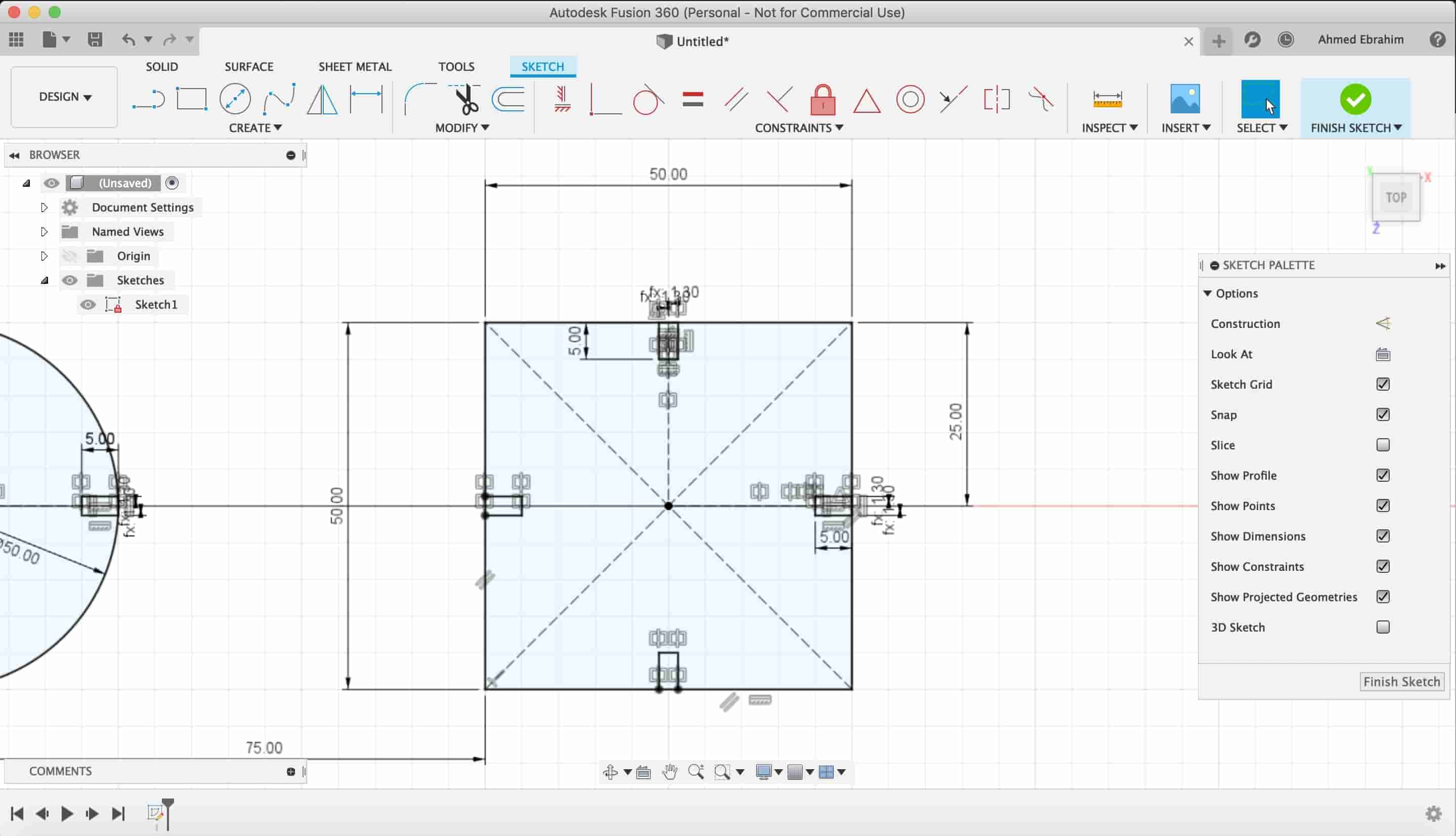
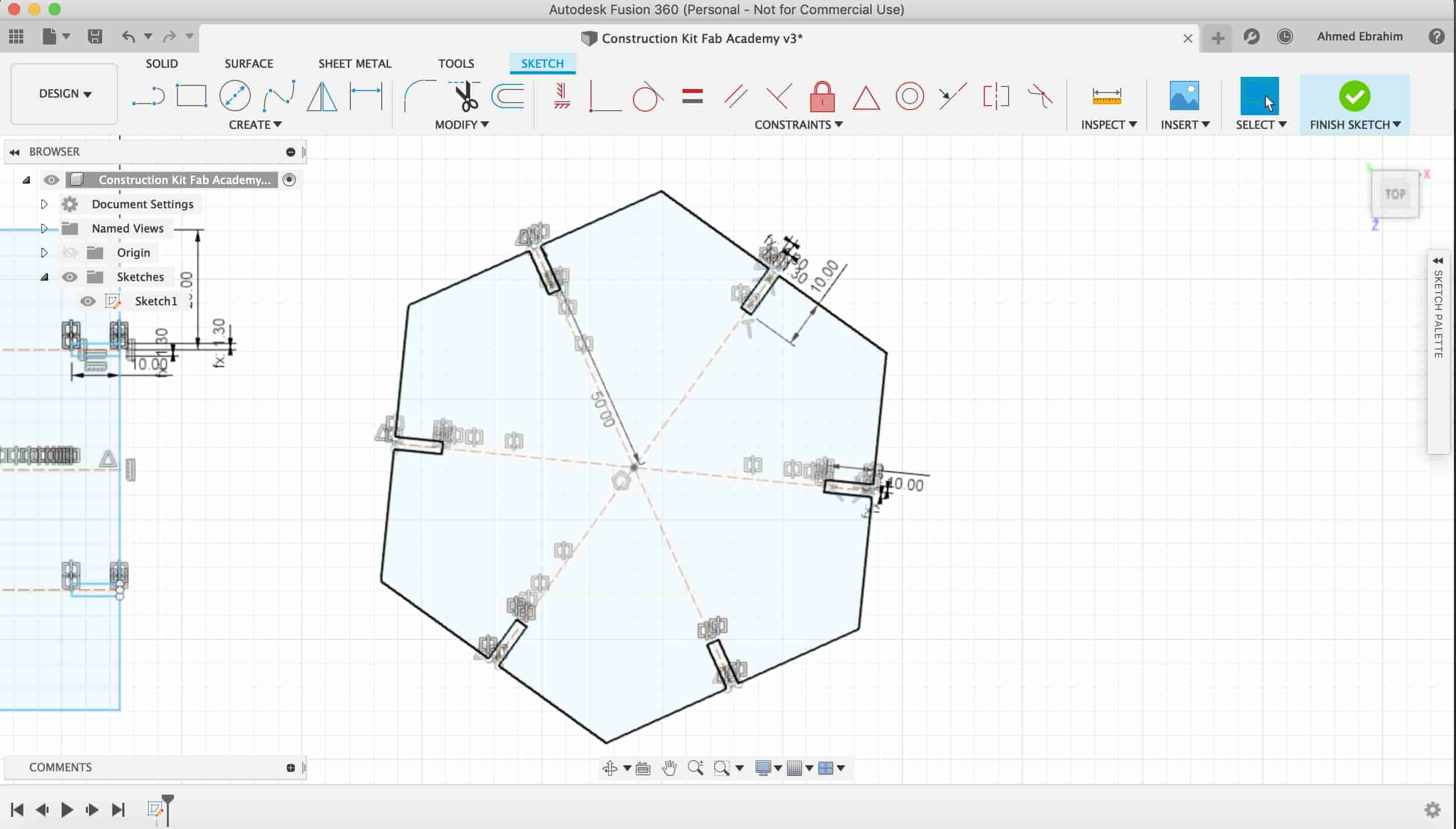
After the square, I draw a hexagon with the same previous technique.
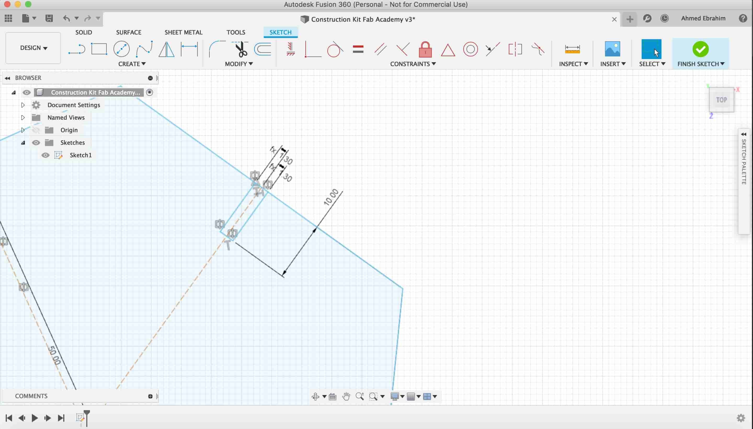
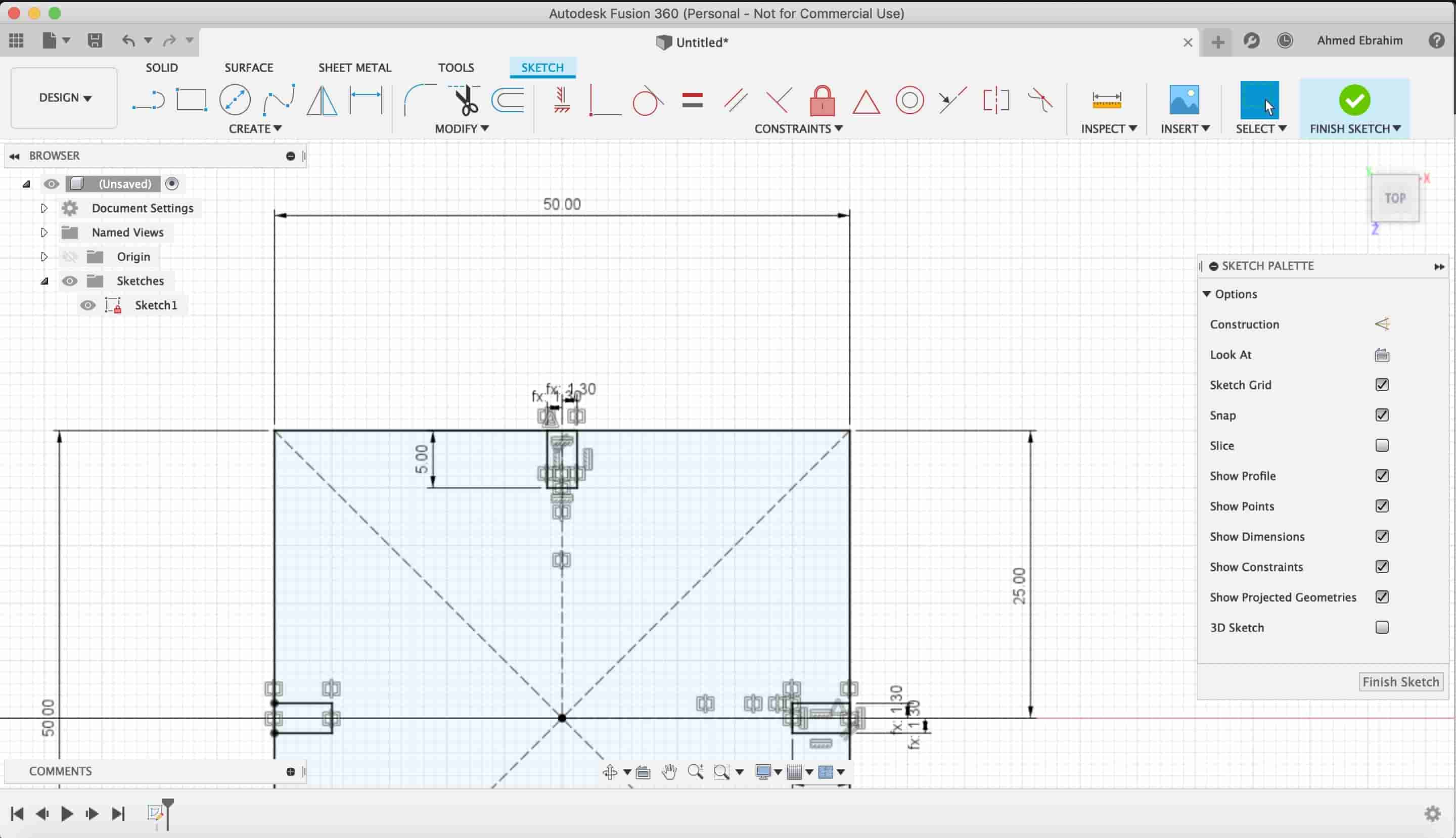
Also, I drew a tall rectangle with some fitting slots around its sides.
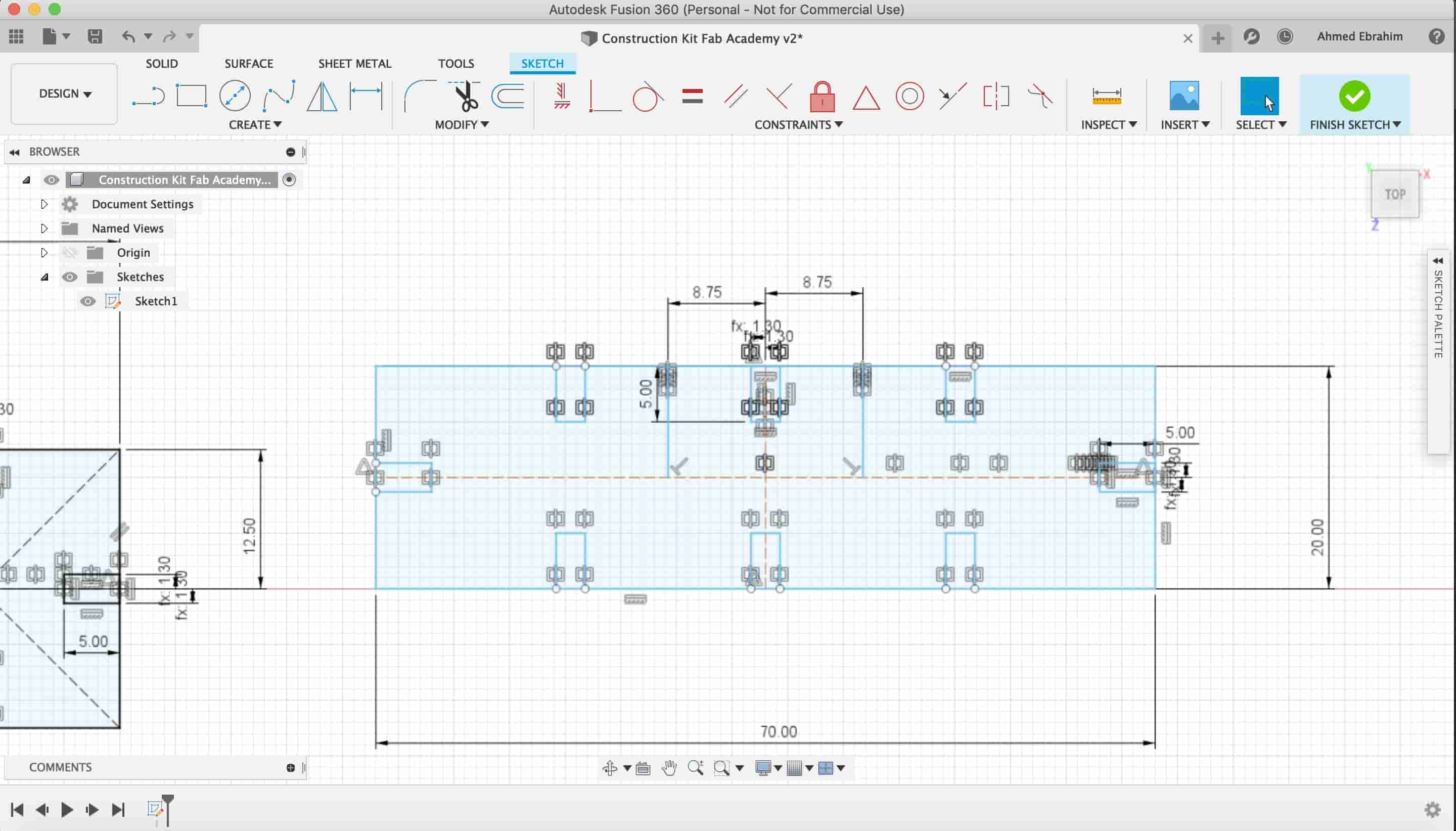
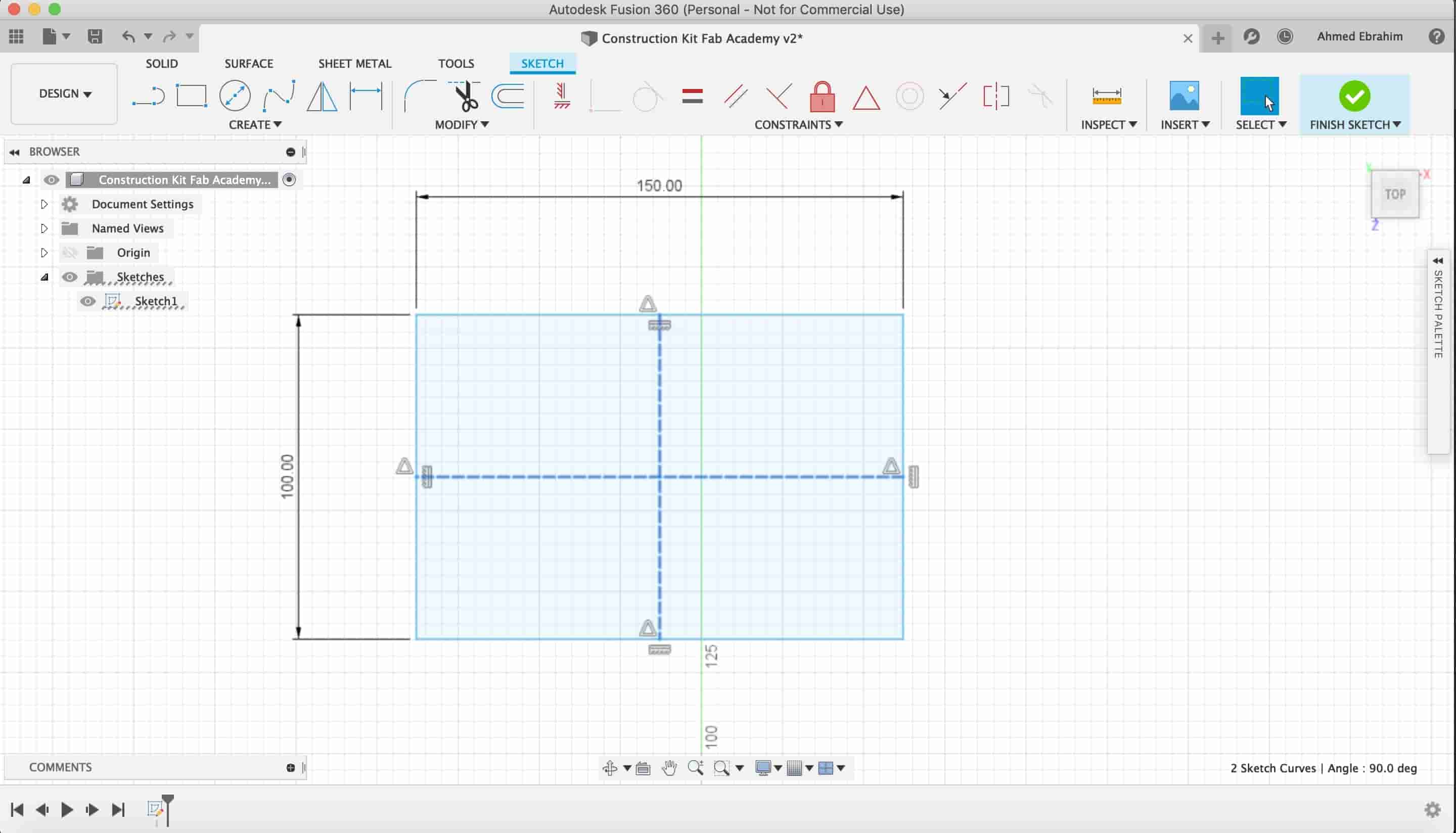
And a large plate for the large constructions.
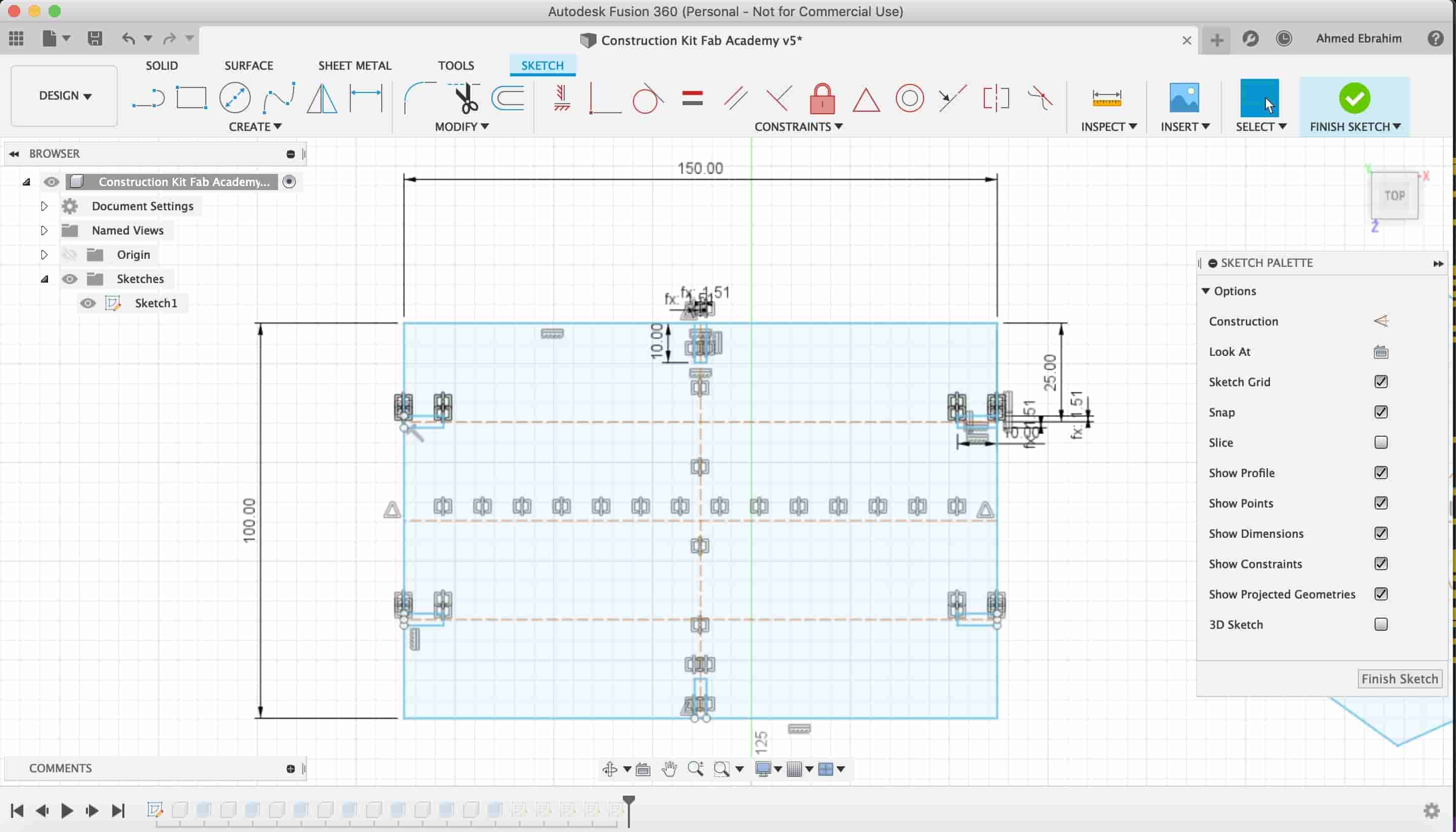
Note: The remaining part between the slot end and the body end should be larger than the slot depth itself.
The distance between the slot end and the part remaining body.
Then we extruded our sketch using the "material thickness" parameter which represnts the stick thickness.
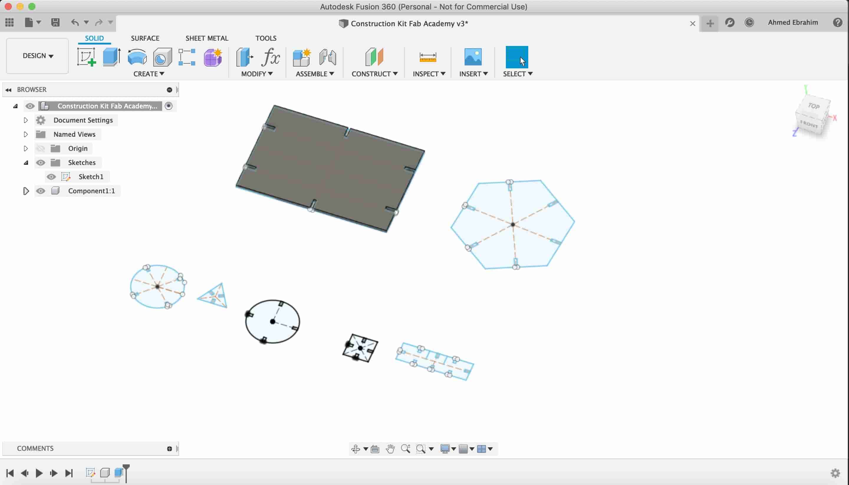
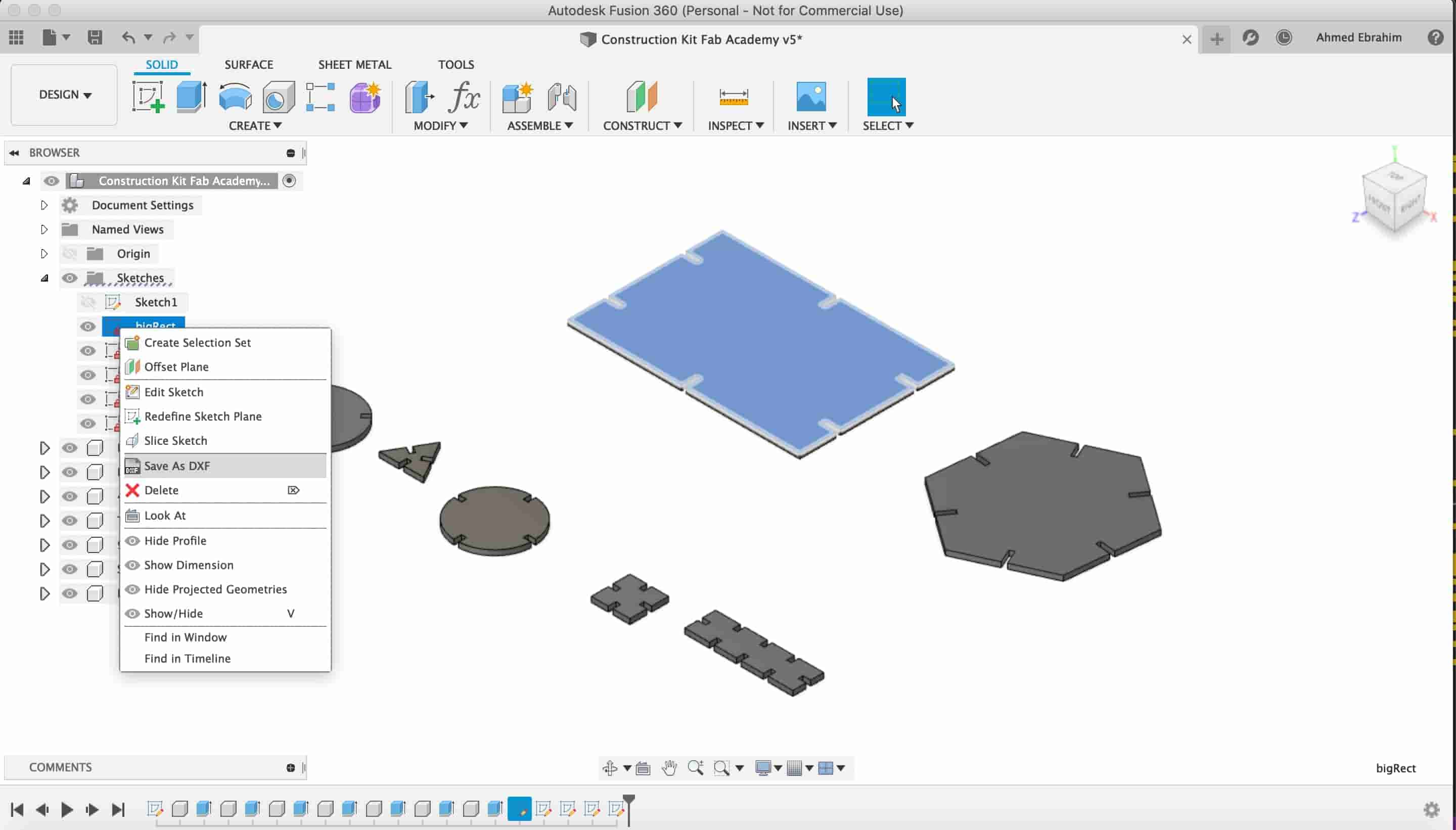
We finished the construction kit parts designing.
After we finished our design, we have to export each shape separately as a DXF file format to be able to import it to the laser cutter machine software. Here you can download the DXFs
Construction Kit Files Download
- The big Rectangle part DXF File
- The circle part DXF File
- The big long rectangle part DXF File
- The polygon part DXF File
- The square part DXF File
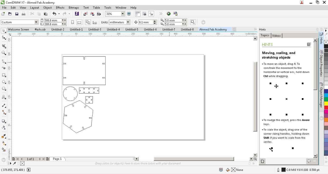
Now, Its time to use the CorelDraw or laser work software to communicate with the laser cutter machine. After importing the DXF files into the CorelDraw software, we set the cut speed and power to 20mm/sec. And 67% respectively.
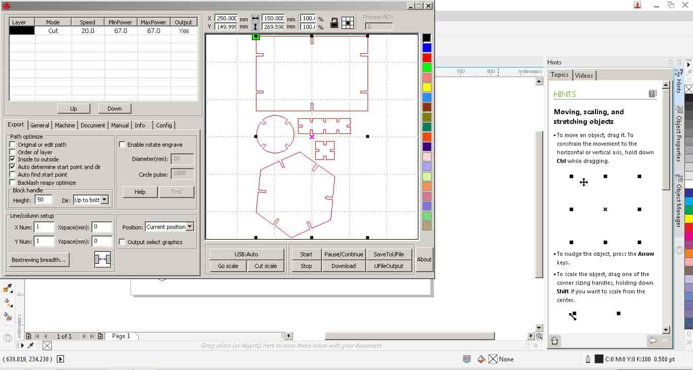
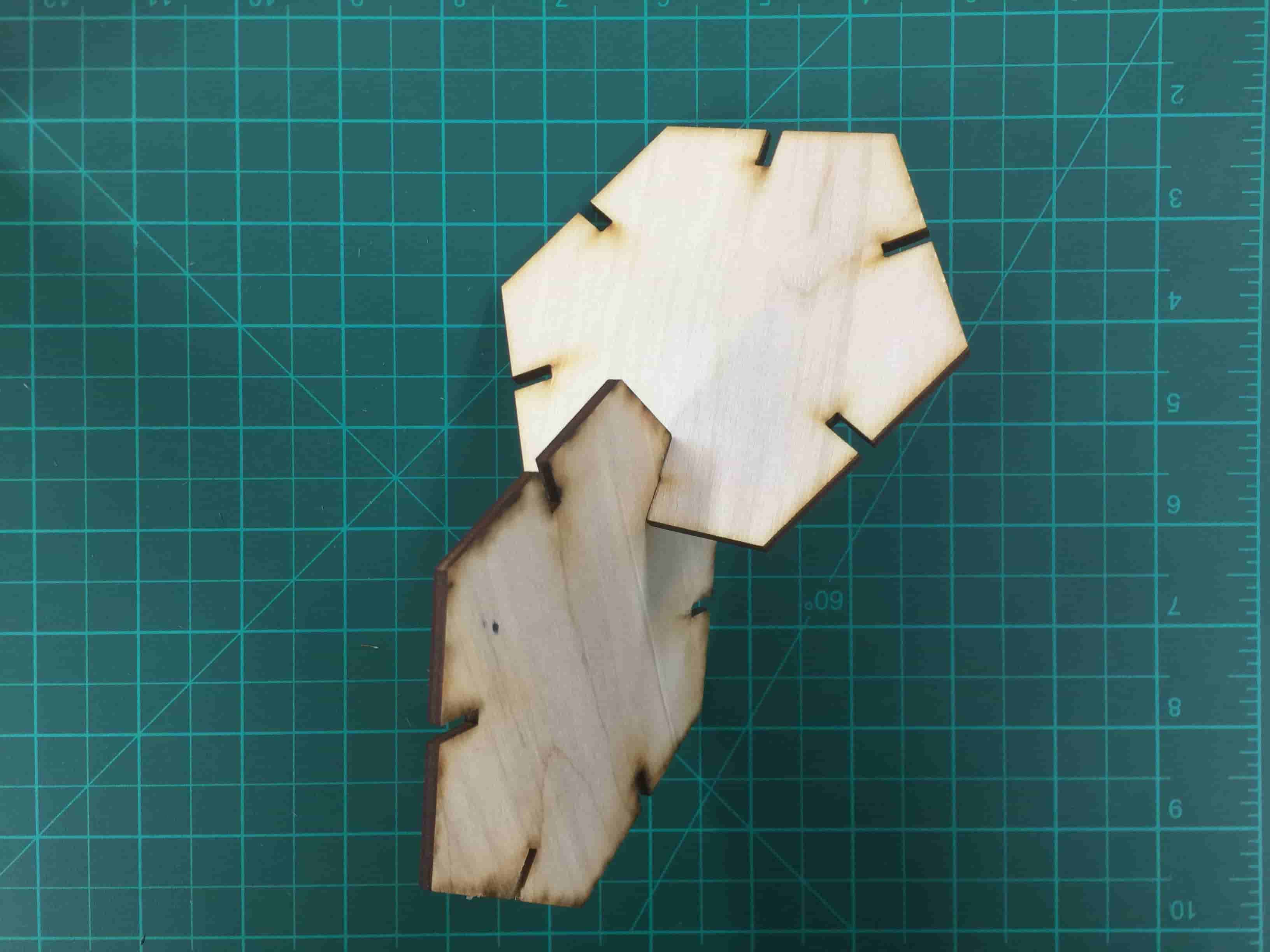
Let the machine do its work but keep your eye on it, Don’t leave it unattended. After it finishes its work, we get the plywood sheet out of the machine and pull the parts out and start playing with it!
The machine finished its work!
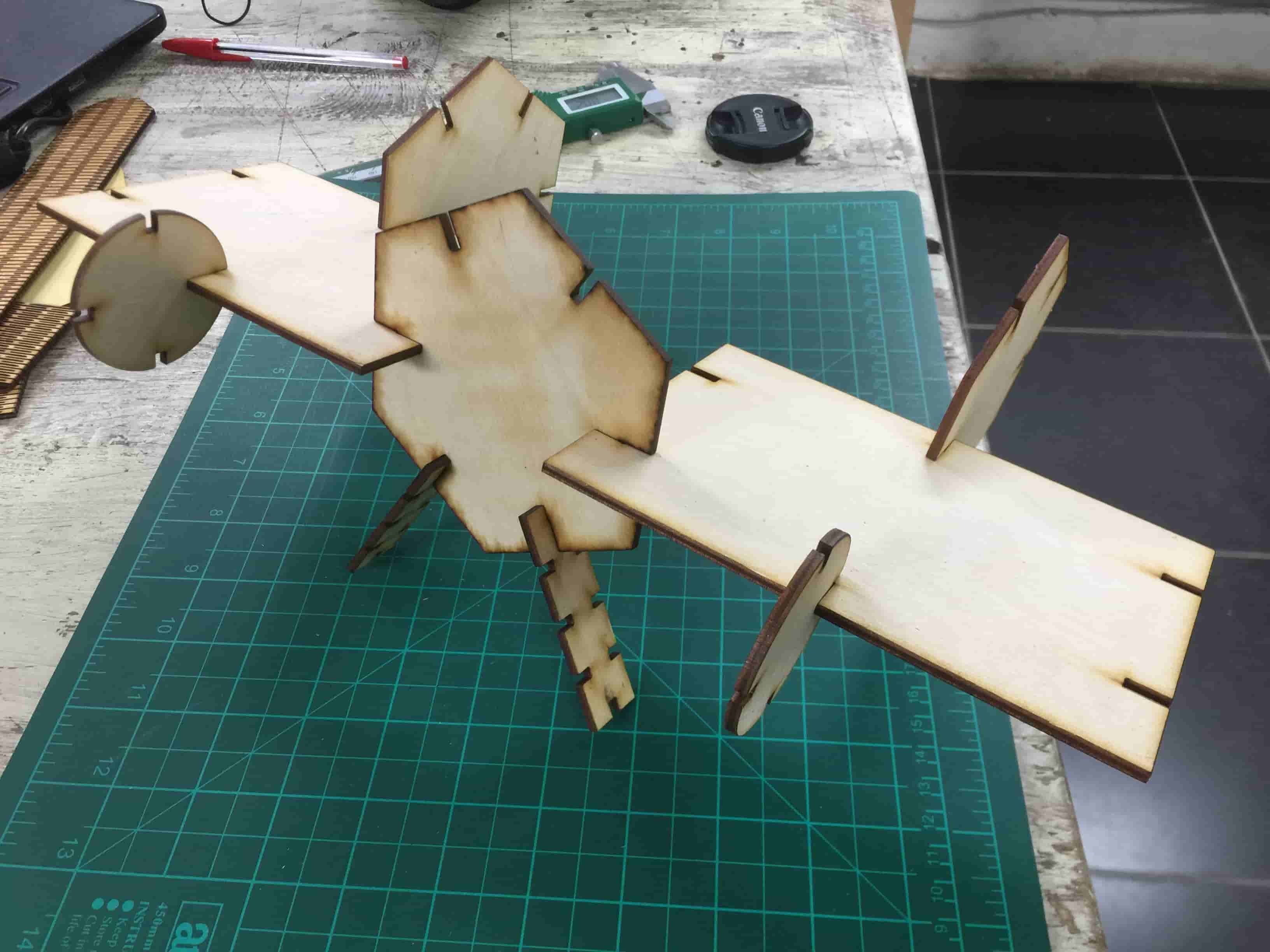
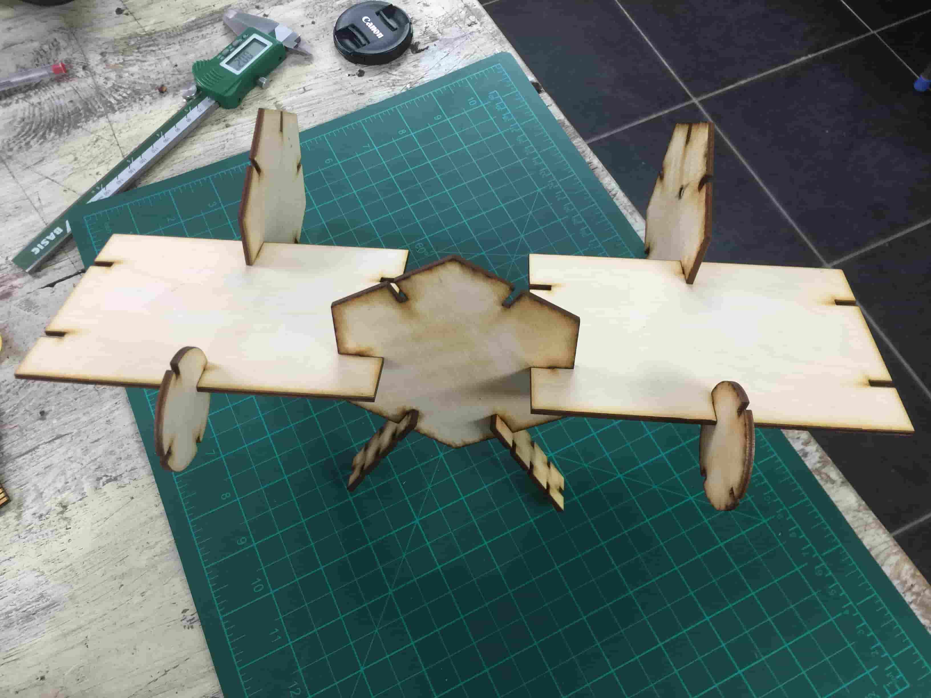
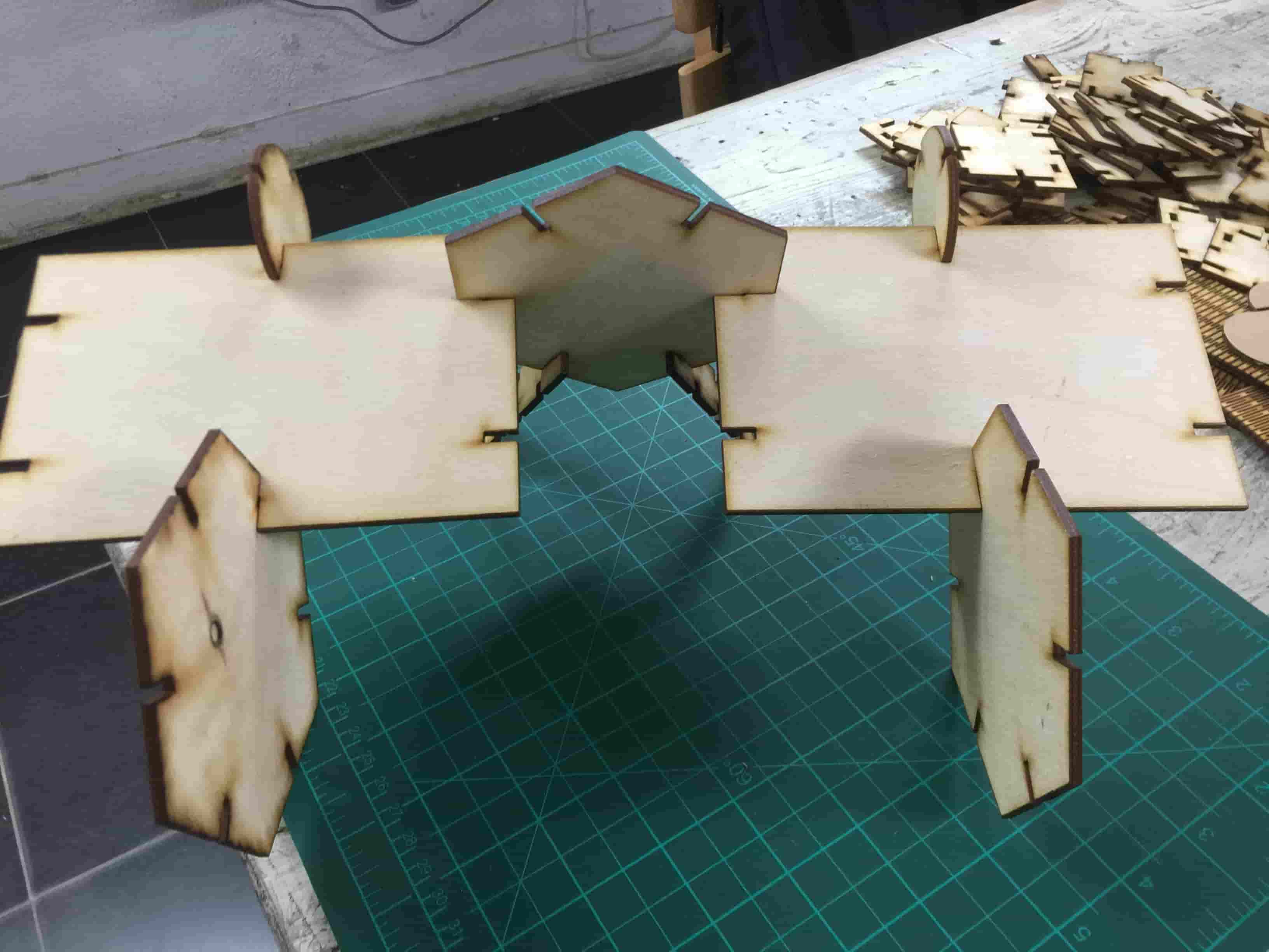
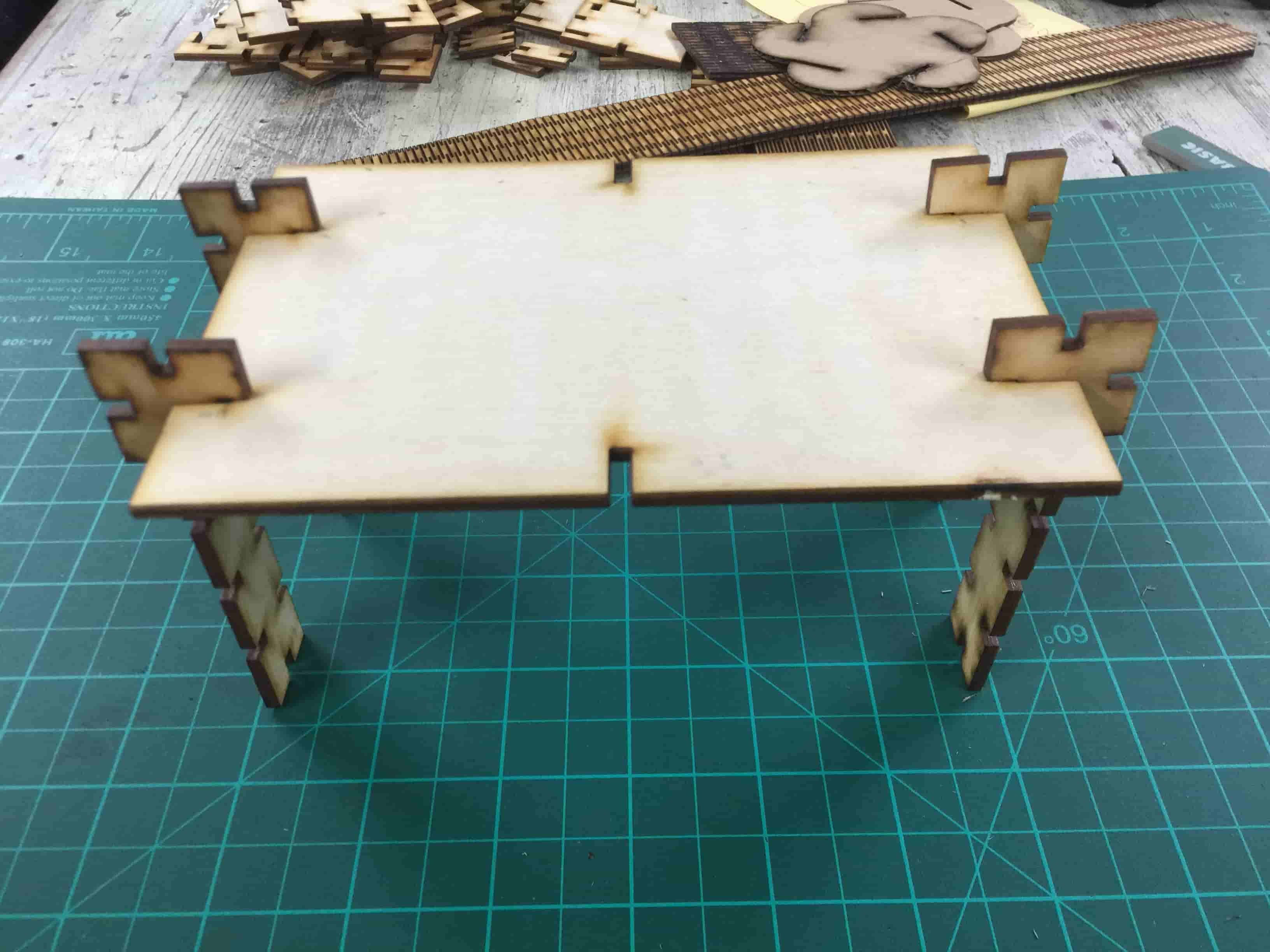
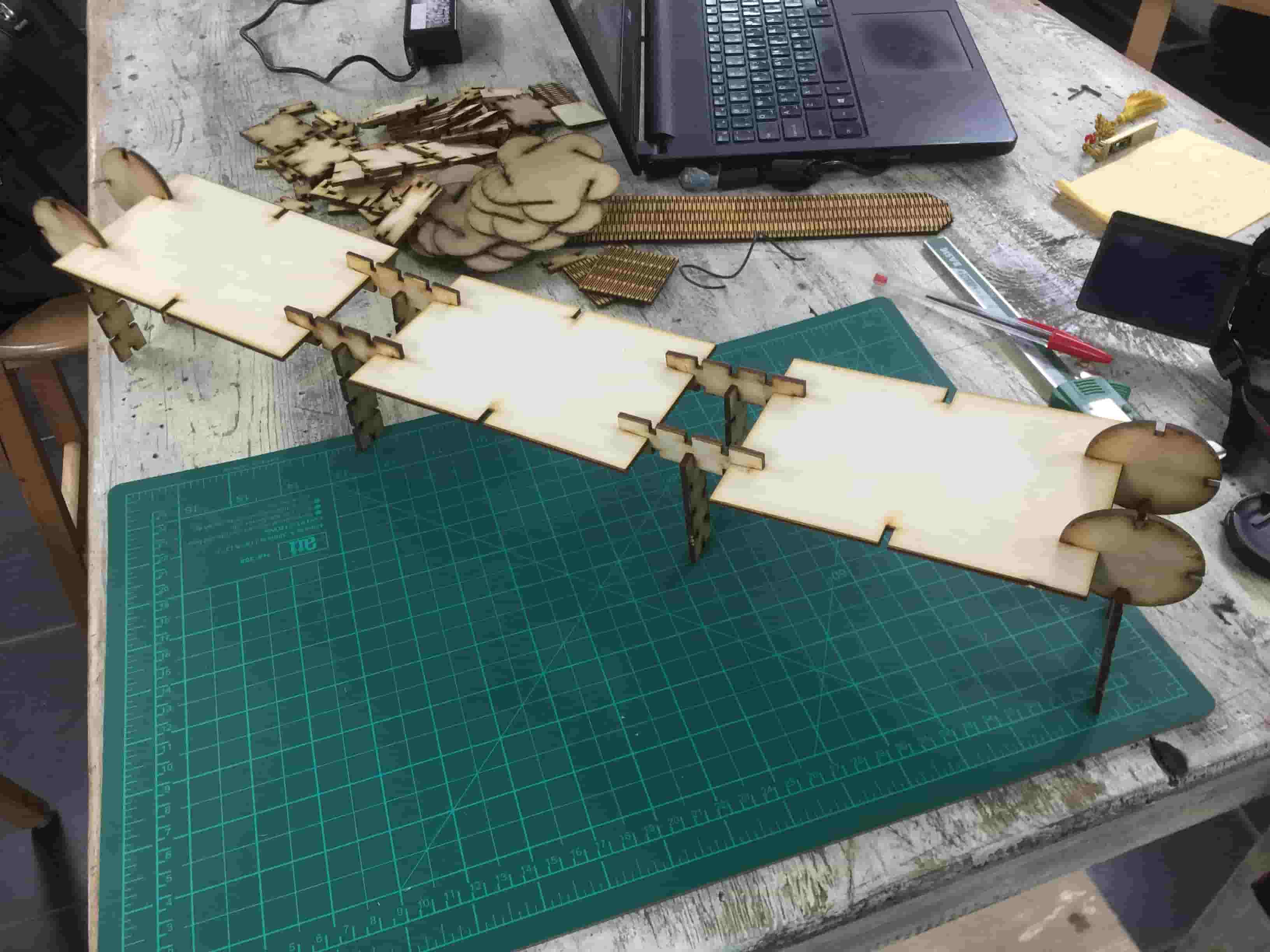
before Cutting a big quantity, we need to test that our dimensions is right and the fitting is good.
I made a helicopter body
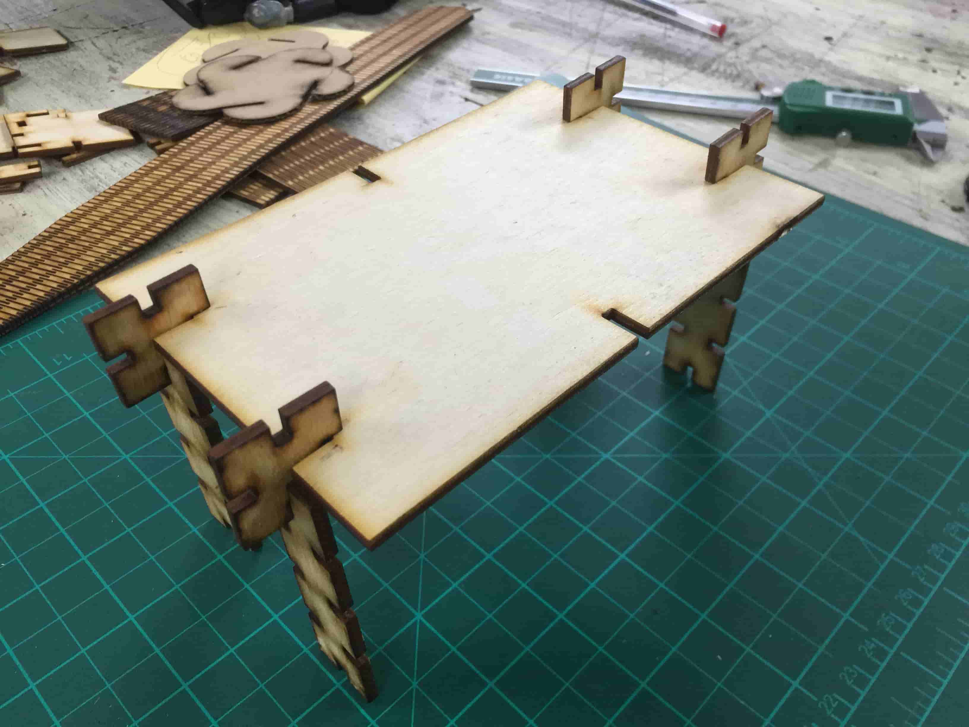
And a small table
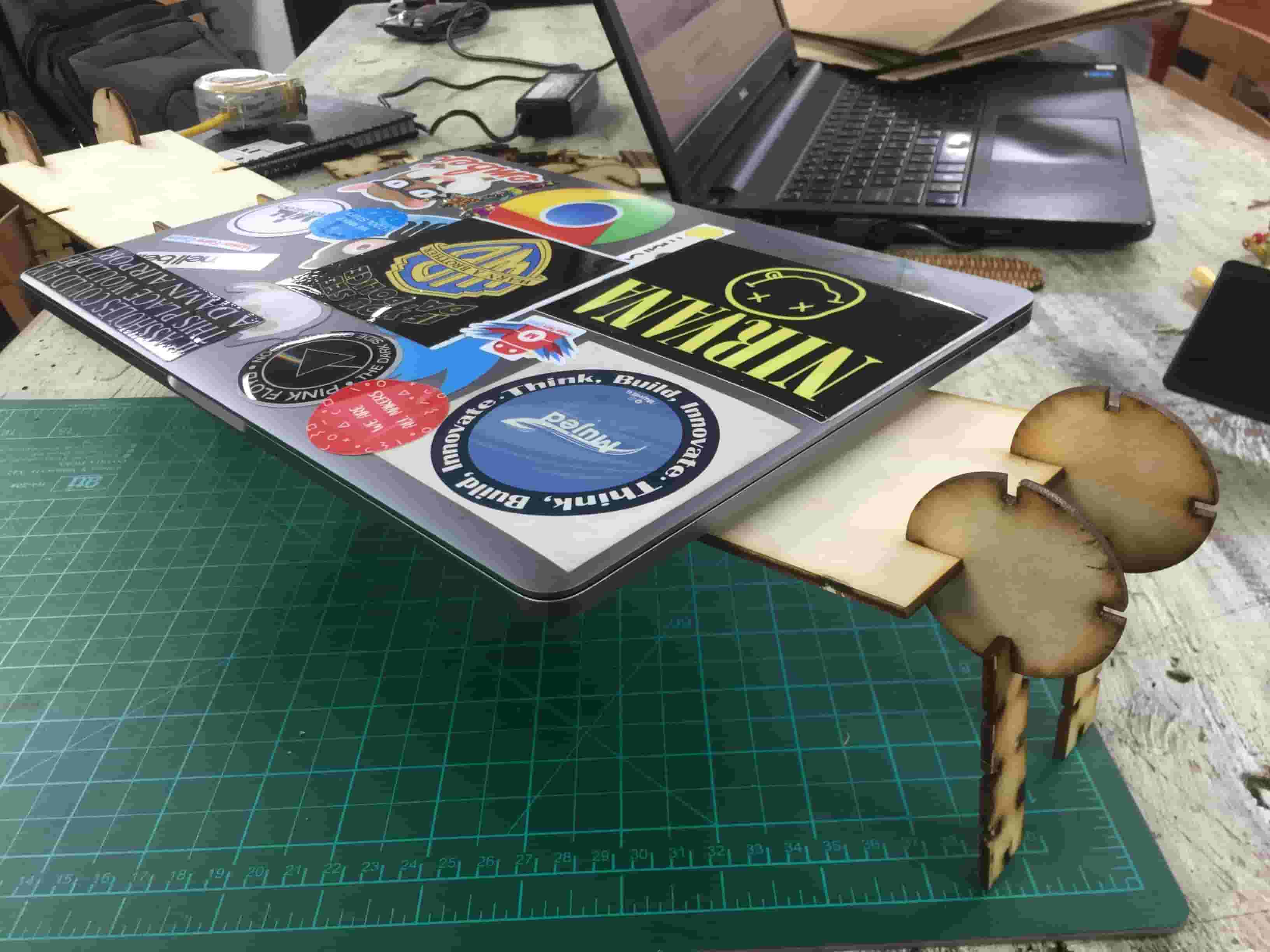
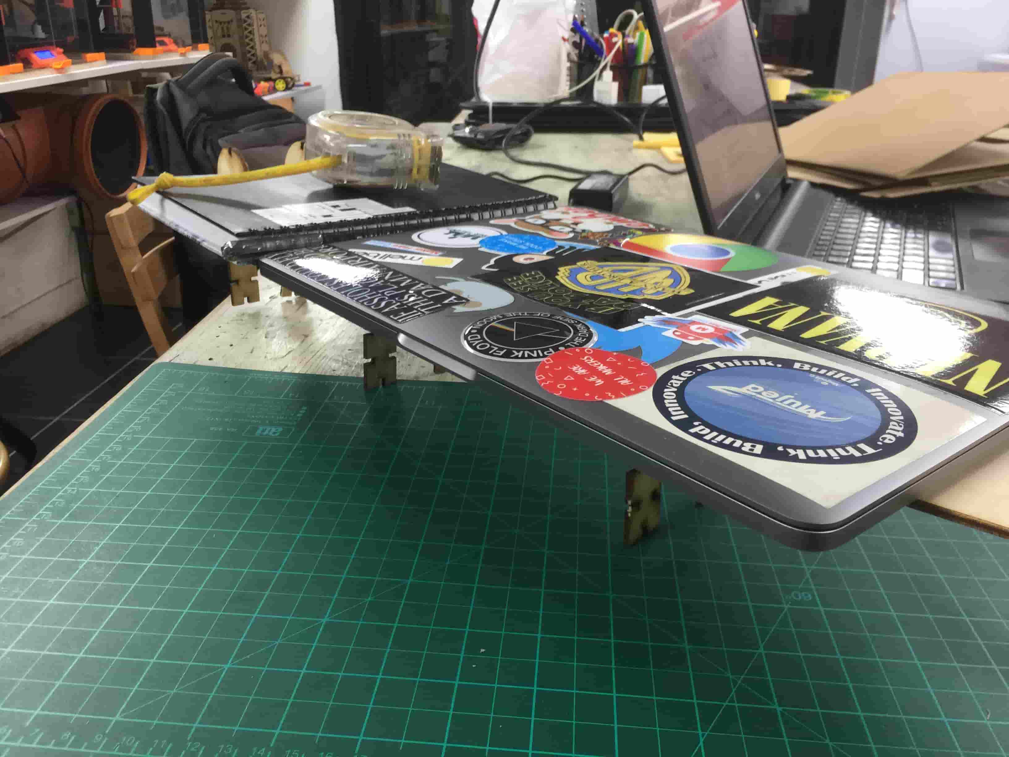
And a small stand that you can put your lightweight stuff on.
Living Hinge
When I was talking with my fellow Ahmed Saeed, we came with an idea. Why not make some wearables something like a cap from plywood! To make something wearable out of wood, we need to make this wood flexible. Here comes the living hinge Inkscape extension role.
Simply, A living hinge is a way to make rigid materials like plywood and acrylic sheets flexible by making cuts in the material. This Inkscape extension is open-source you can check it from this link (https://github.com/drphonon/Inkscape_LivingHinge).
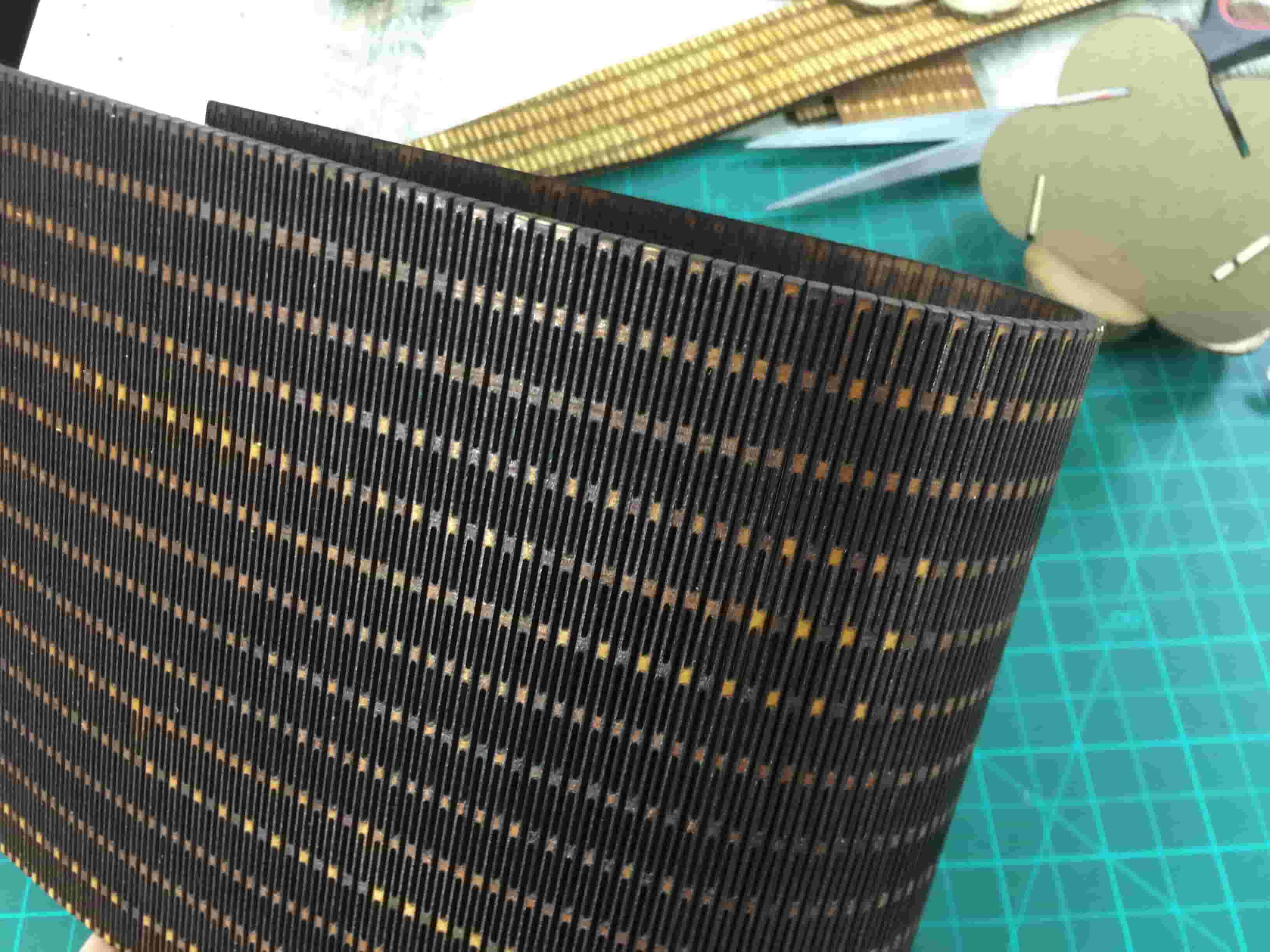
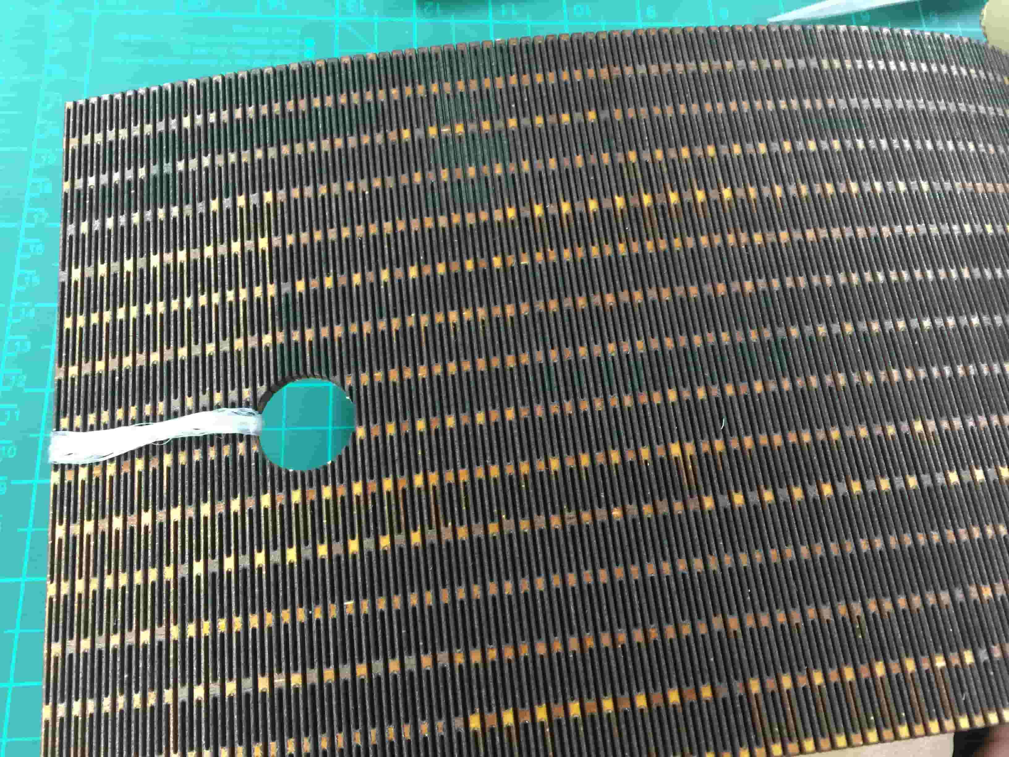
I measured my head around and it was 60cm. But the laser cutter machine that we have in the place its dimensions is 50*30cm. So, I’m not able to make a full cap. But, I made a cap of length 48cm and a 20cm height. Then I secured it around my head with a small rope.
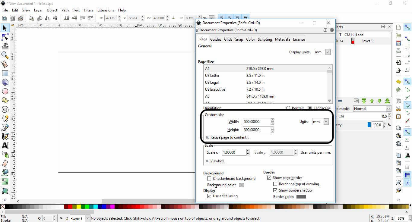
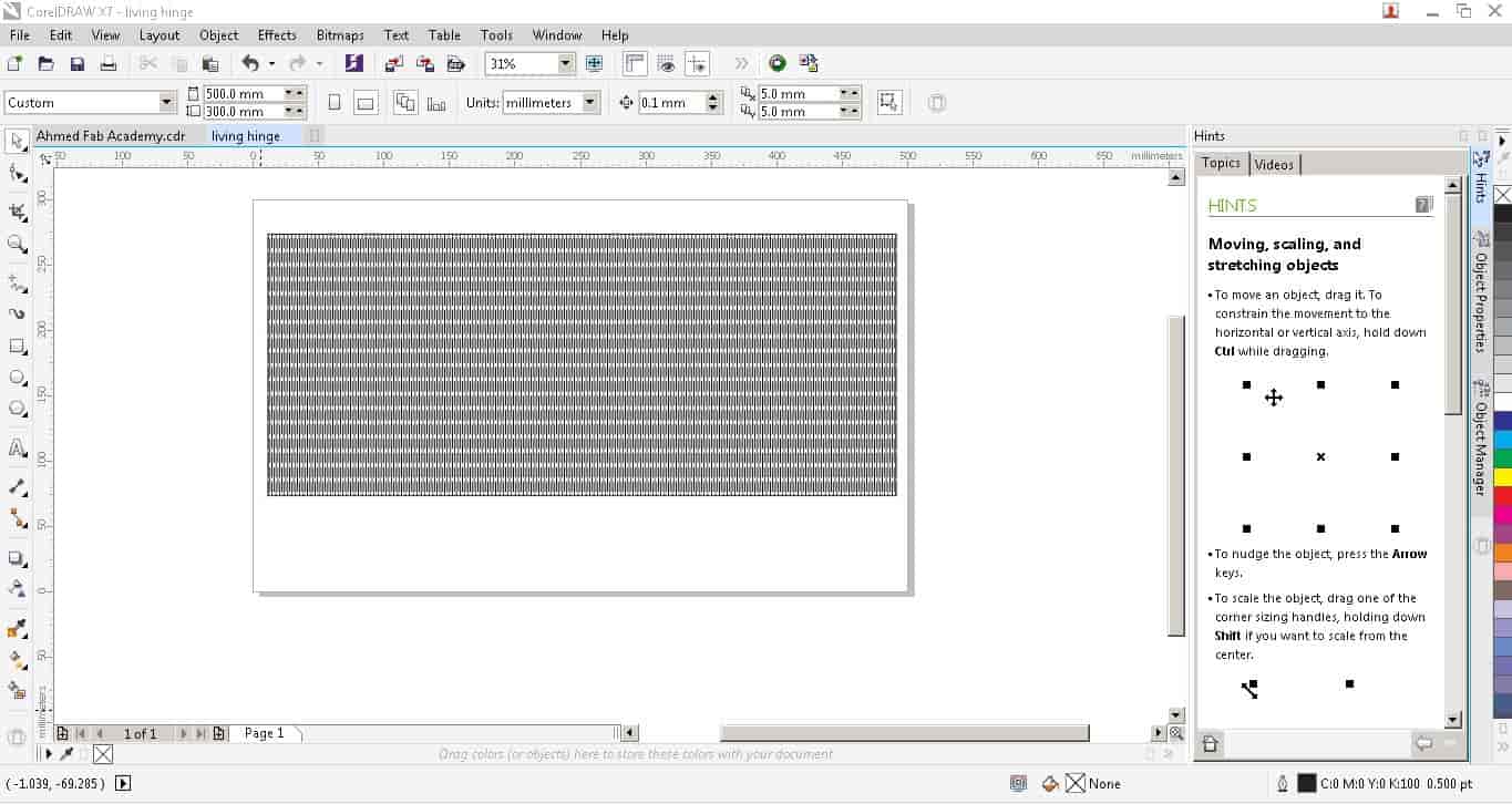
Firstly, we need to set the document size according to our laser cutter machine which is 50*30cm
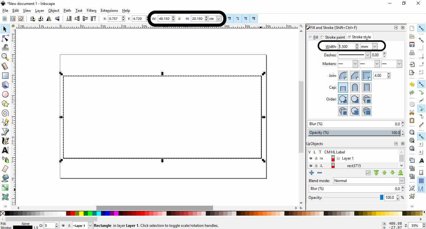
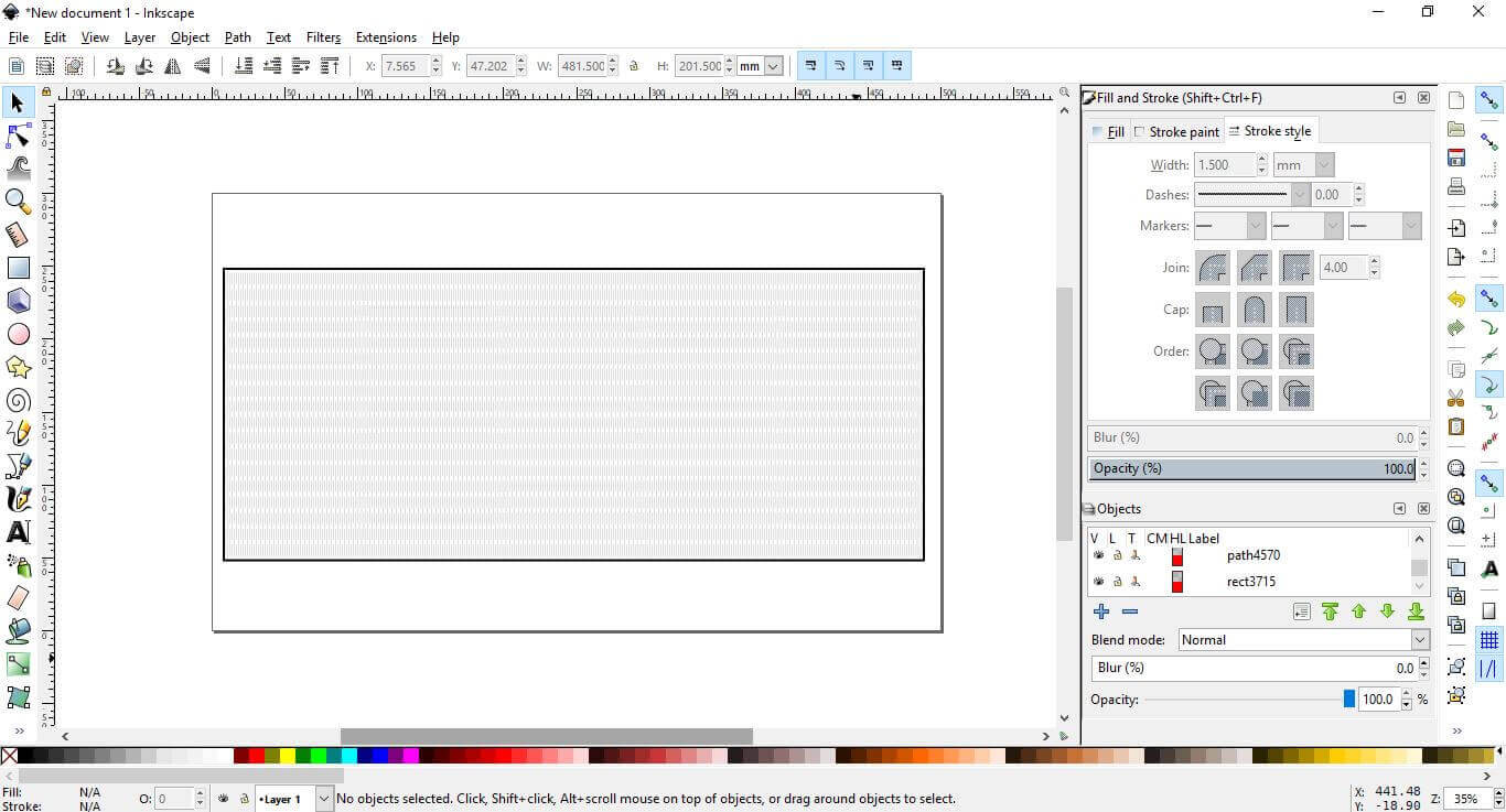
Then, I drew a 48cm*20cm rectangleon Inkscape. And, Set the stroke width wo 1.5mm
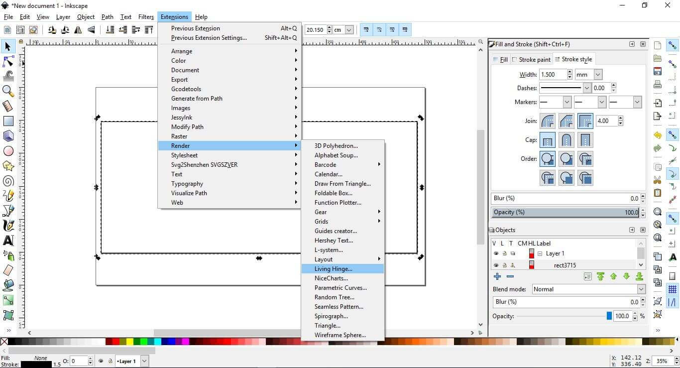
After selecting the rectangle, from the toolbar select render -> Living Hinge…
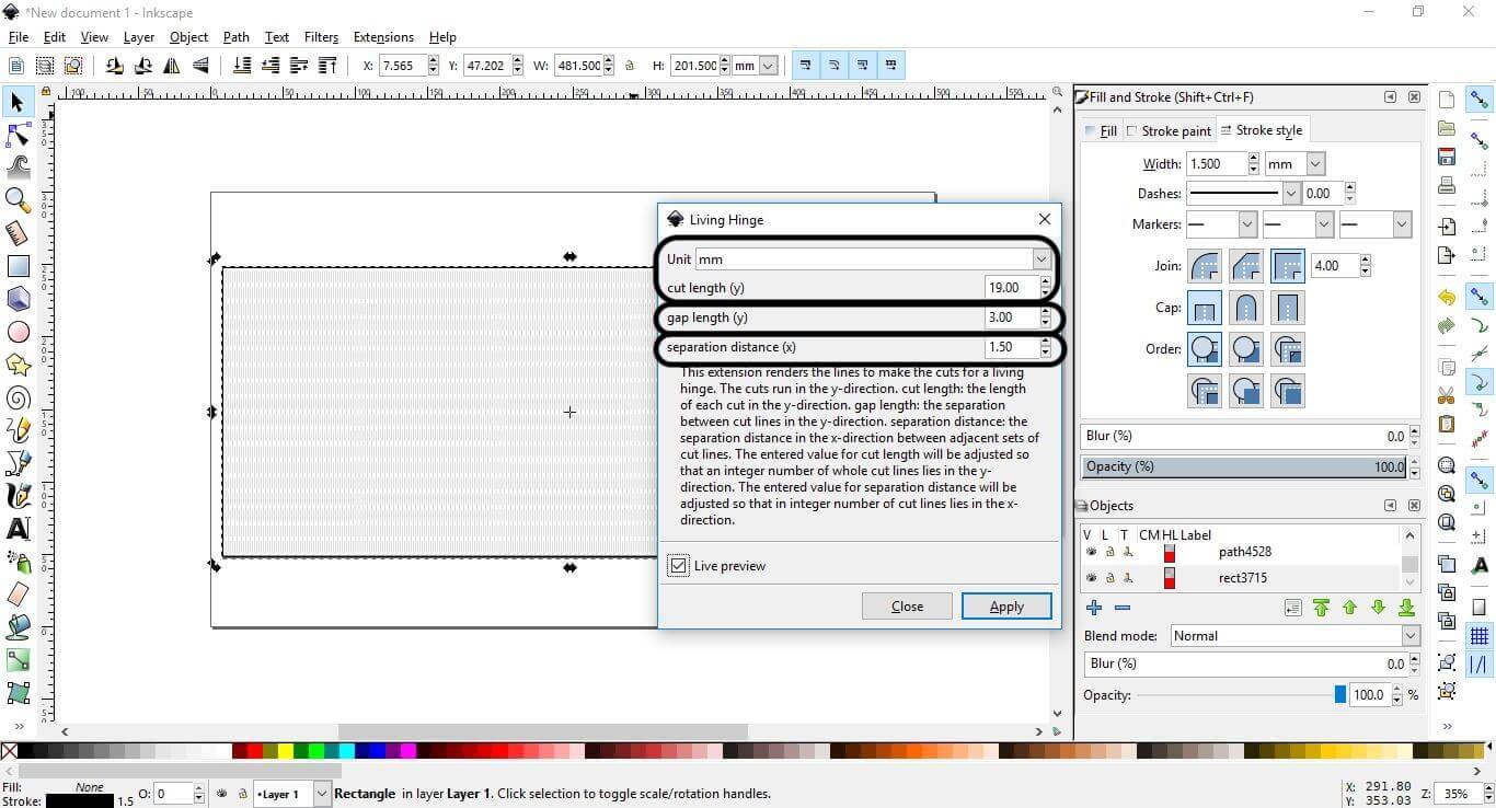
Setting some parameters, The cut length which is the length of the line which will get cut, Gap length is the distance between each cut line in the y-axis, separation length is the distance between the line in the x-axis.
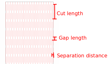
Here is the rectangle after applying the Living Hinge extention on it
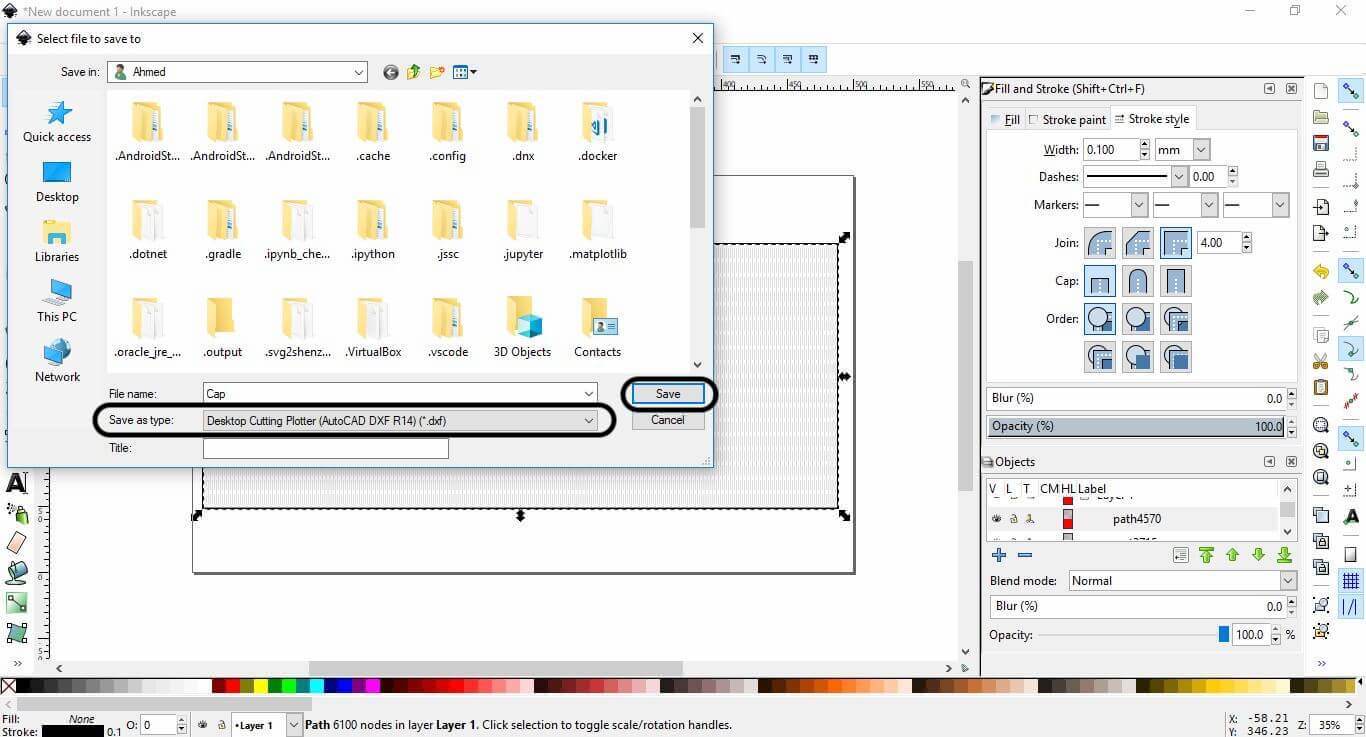
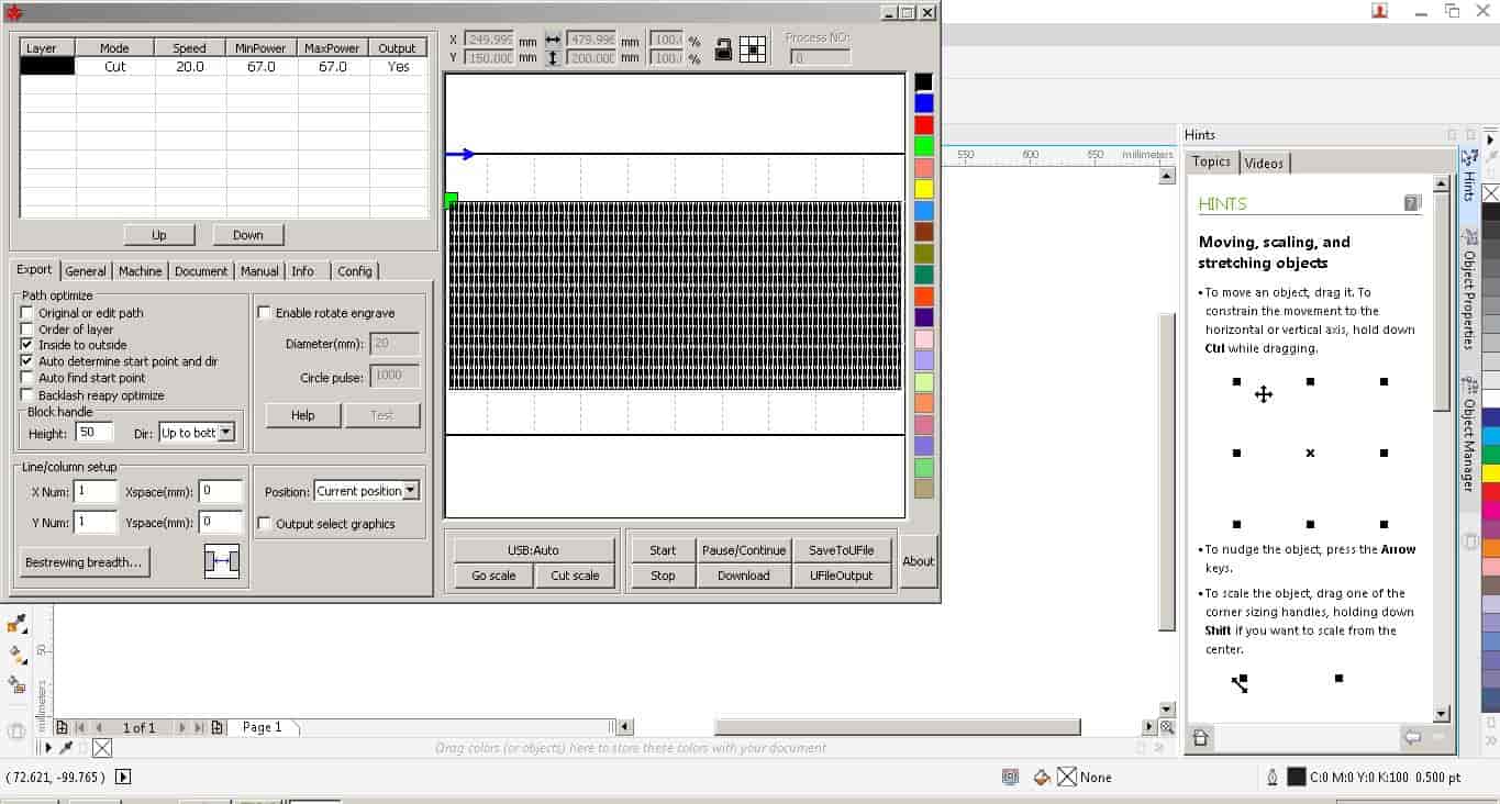
The remaining step is to save a DXF file format so we can send it to the laser cutter machine, Import the DXF file to the CorelDraw software as the previous step, setting the power and speed to 70% and 23mm/sec. and start cutting.
Import the DXF file to the CorelDraw software as the previous step, setting the power and speed to 67% and 20mm/sec. and start cutting.
Here is the Plywood cap in action after cutting. Actually, I'm impressed with the results :D

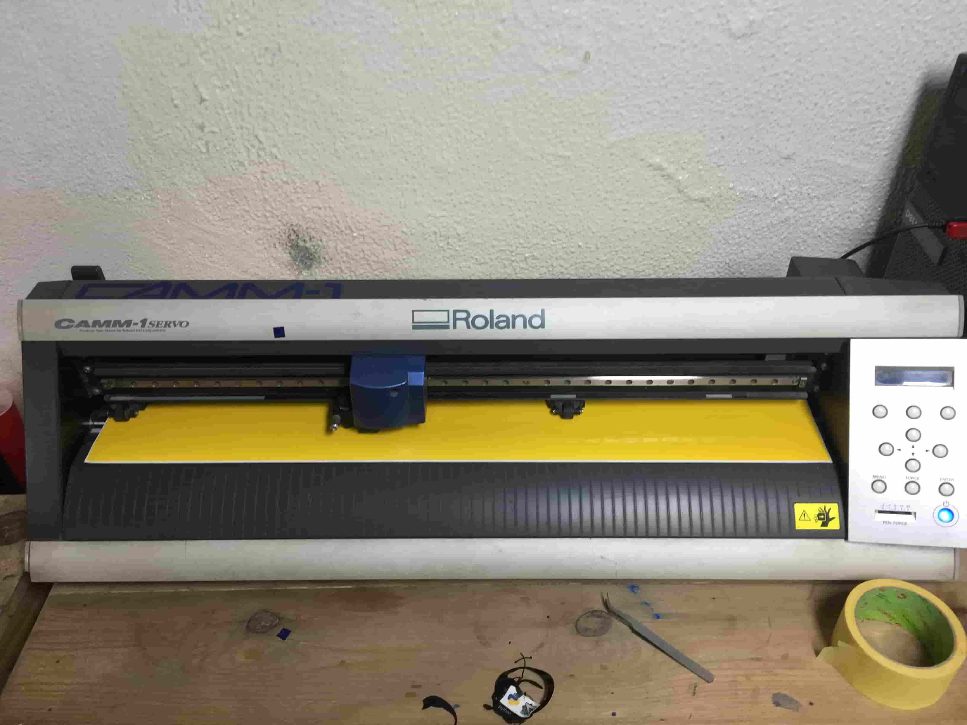
Vinyl Cutter machine
Before diving in any machine characterizing and usage lemme introduce our Fab Lab baby Roland CAMM-1 Servo. is used to make shapes from solid color vinyl pieces then the vinyl can be stuck on a variety of surfaces like Laptops, Doors, T-shirts…. Etc
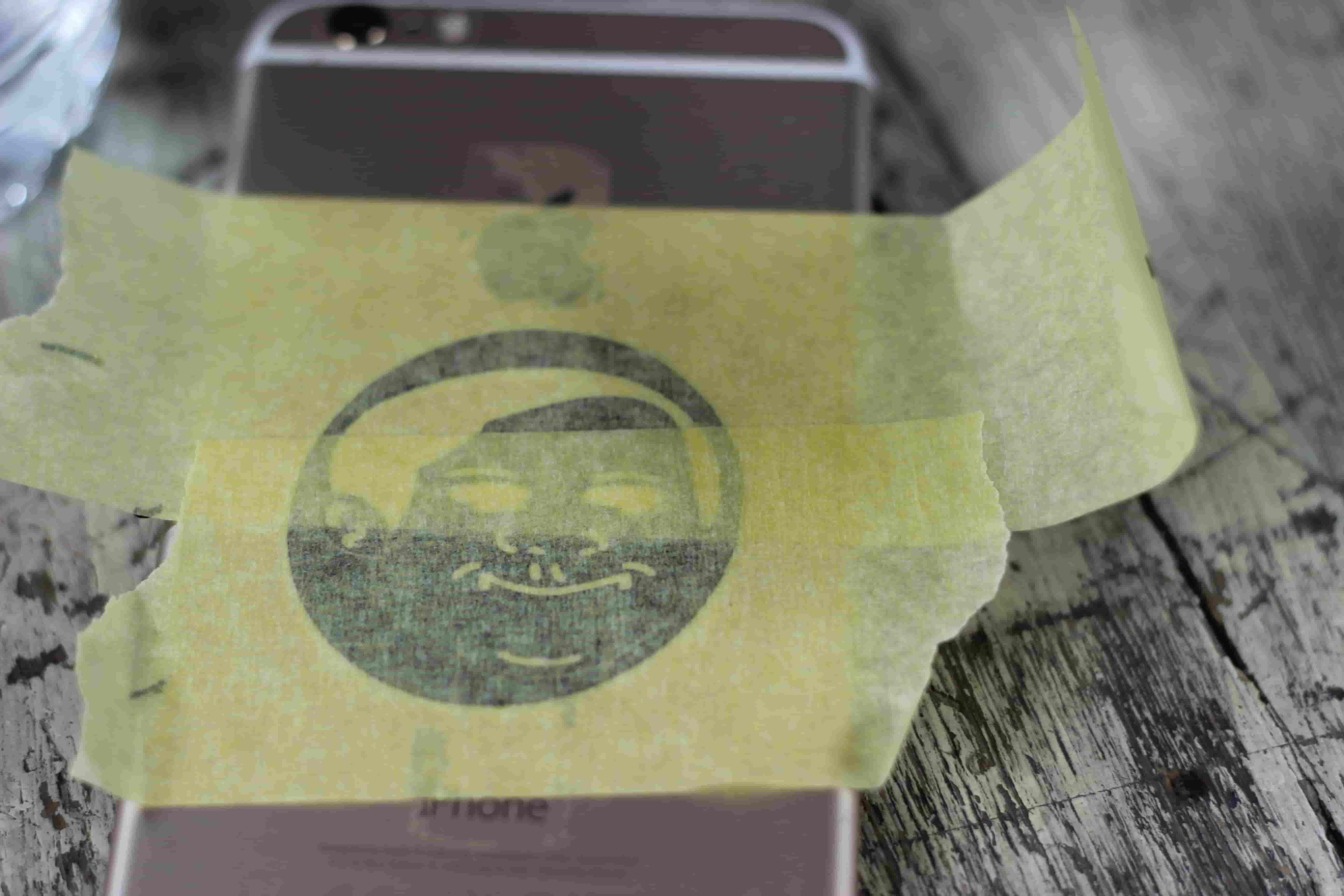
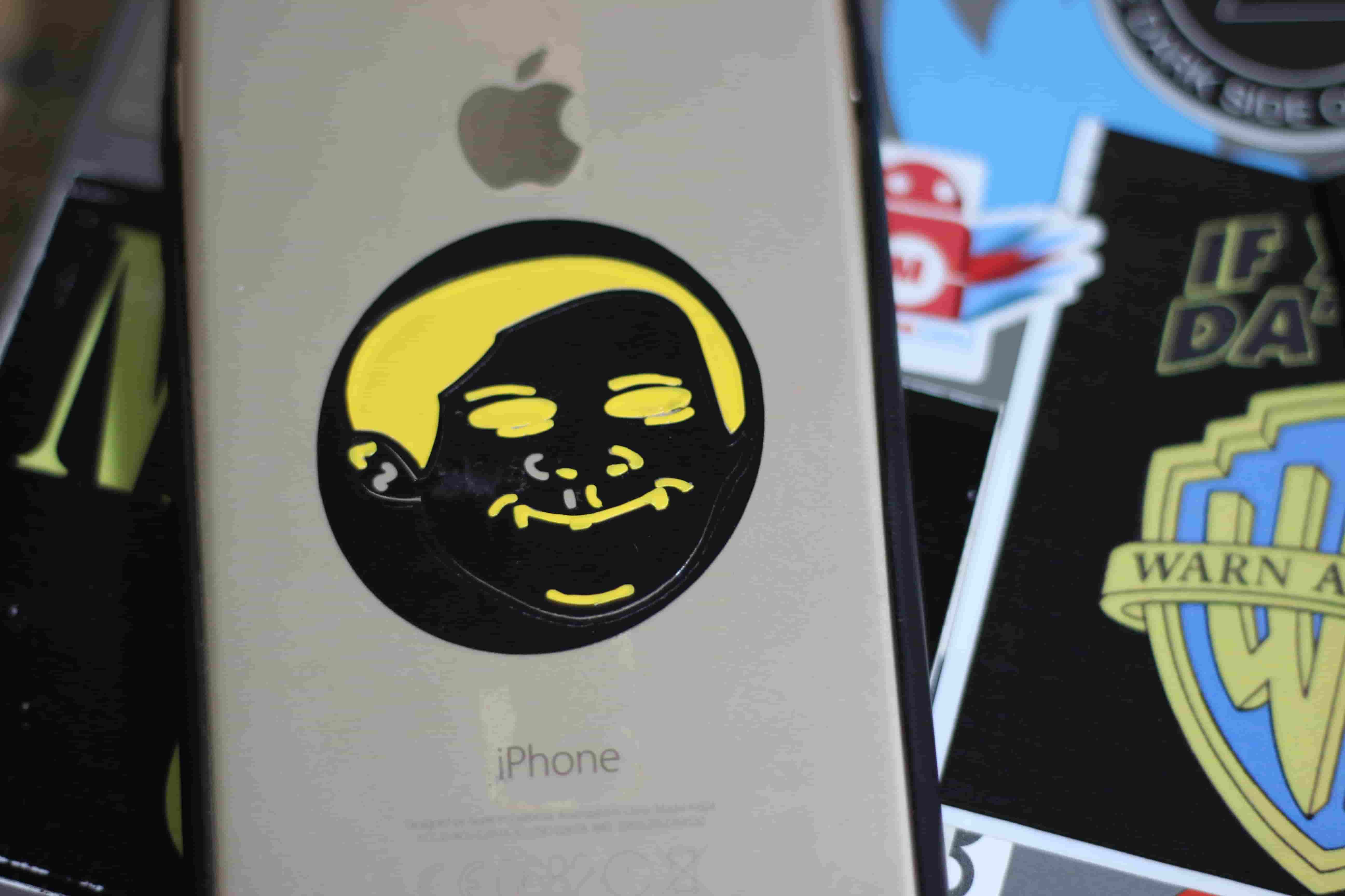
If you read the “about me” part on the home page you know that I love memes. I wanna make a meme sticker. I was very excited to make it, it’s my first time ever to use the vinyl cutter machine. That’s why I forgot to take screenshots from the software to show and explain the process steps. But I’m going tomorrow to the Lab and I will solve that problem :D
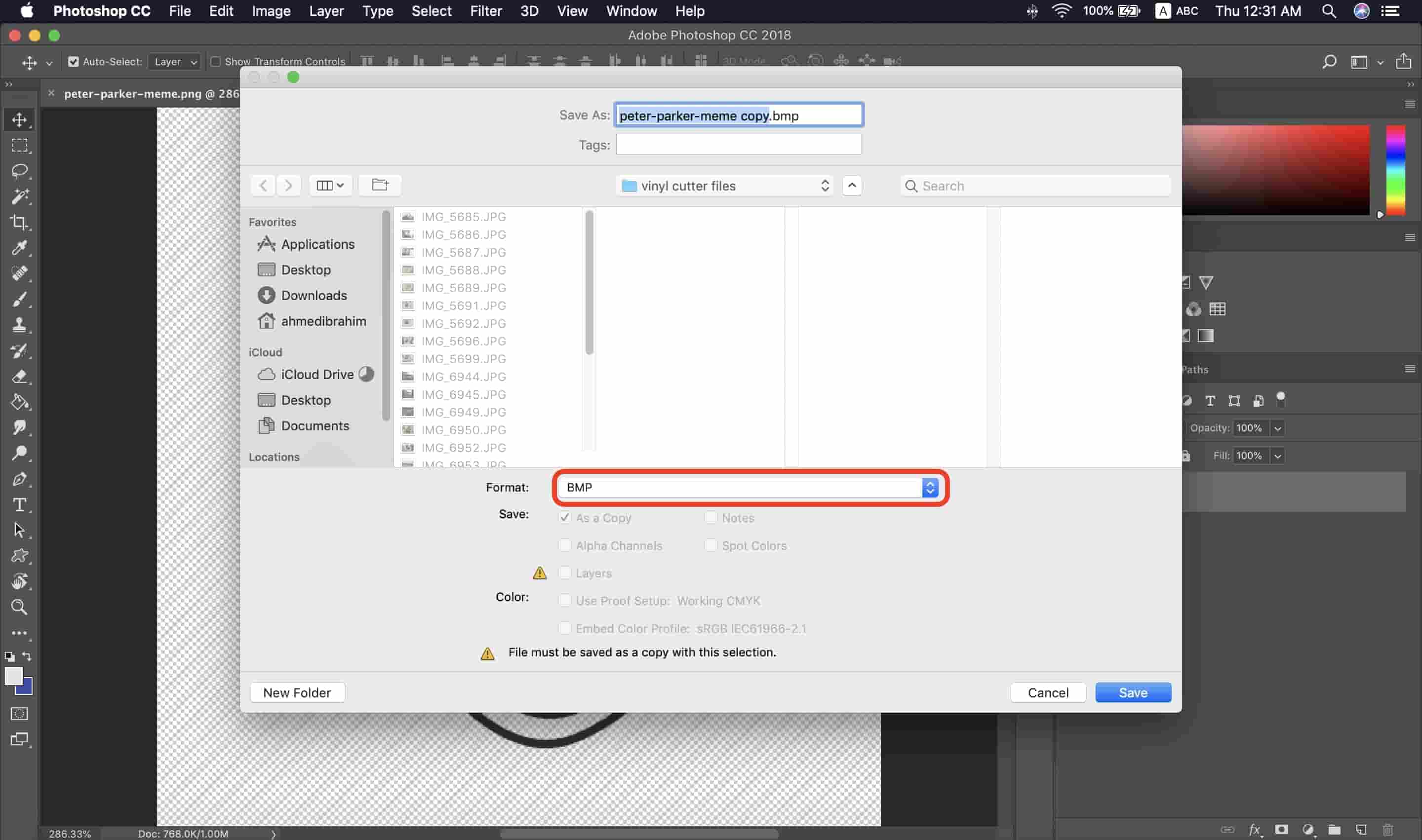
First thing, I googled for a good PNG meme image, I found one and I downloaded it. Then I opened this PNG image on Photoshop and I exported it as a BMP file format

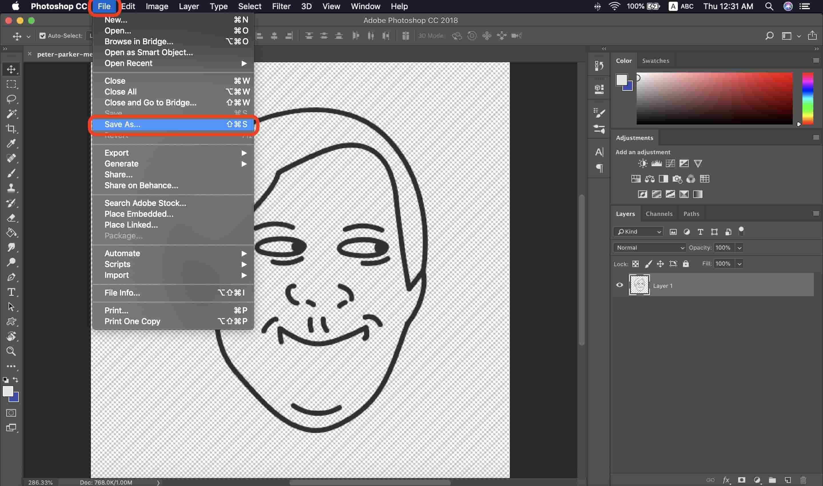
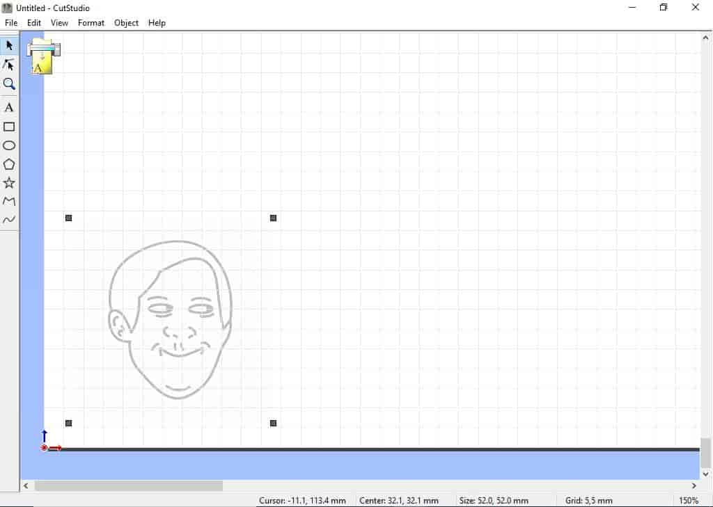
Then I Imported the BMP file to the CutStudio software.
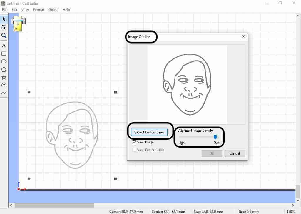
After resizing the image, right-click in the selected file, and choose “Image outlines” then adjust the image density until you get the cleanest outlines. Then click “Extract contour lines”
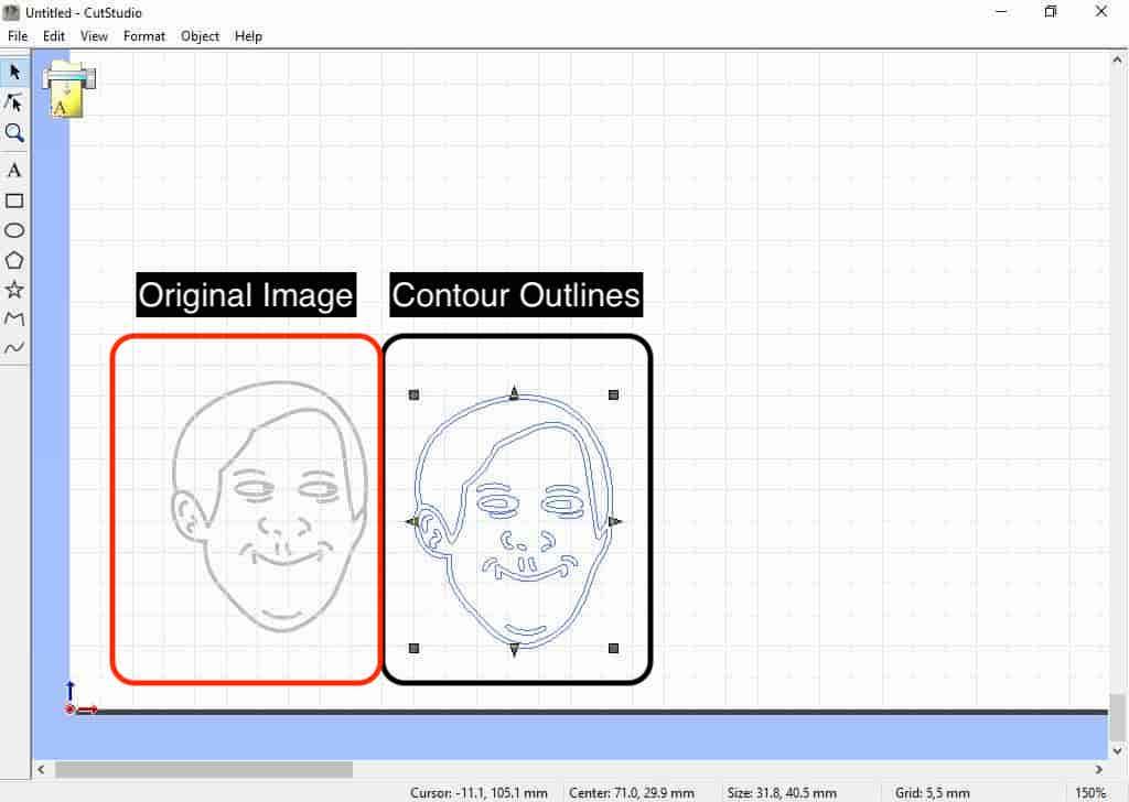
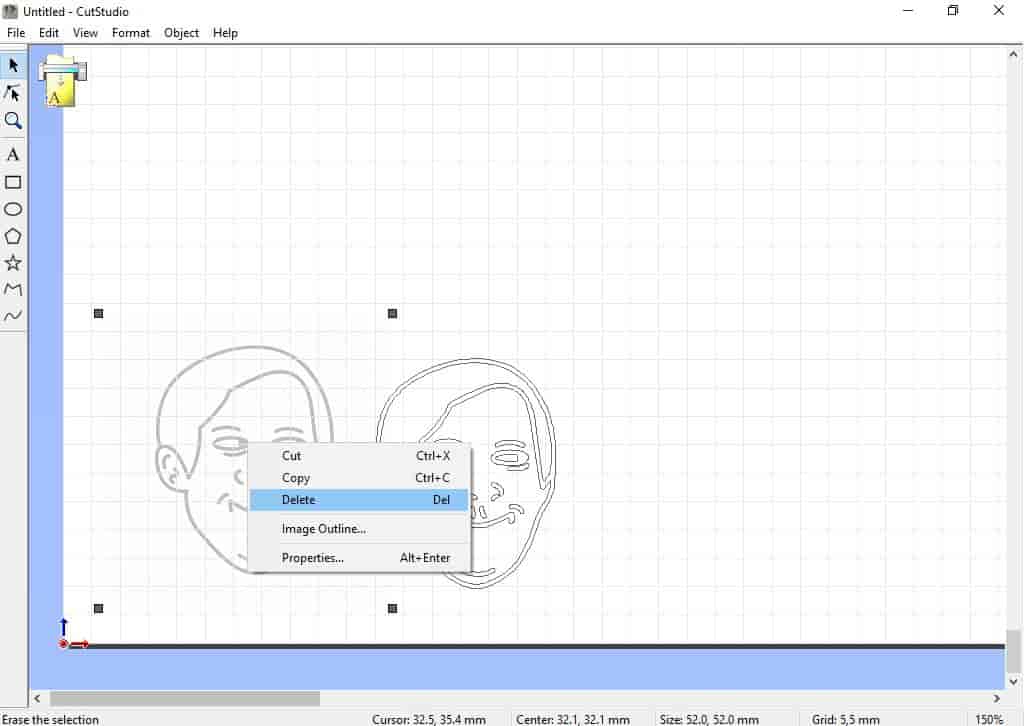
The extracted contour is what the machine will follow to cut, we need to Delete the original image and keep only the contour on the grid.
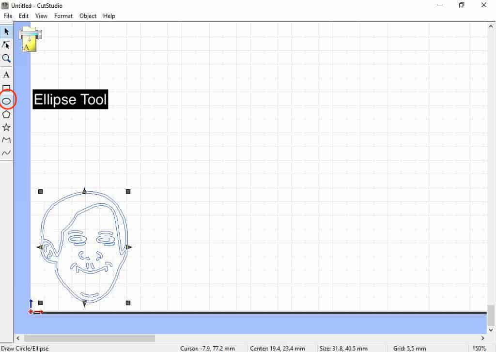
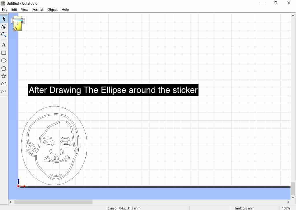
then, I drew an ellipse around it to make it look cooler.
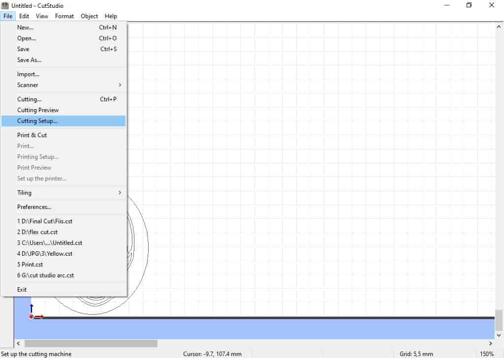
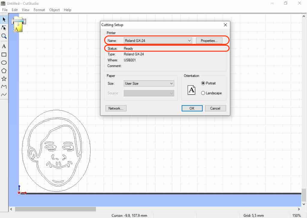
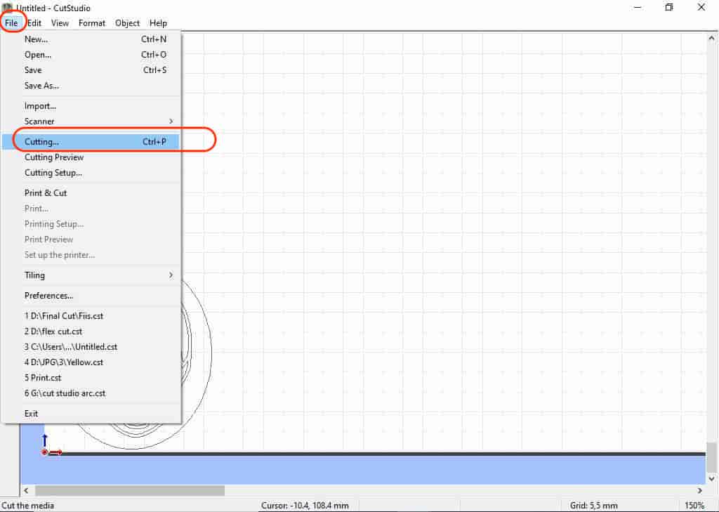
Before cutting, Don't forget to make sure that the cutting setup is correct and the machine is ready. We can check that from file --> cutting setup
Don’t forget to set the origin of the machine which is the point (0,0) of the X-and Y-Axis end effector before starting the cutting. Long press on the "origin" button to set the machine origin point.
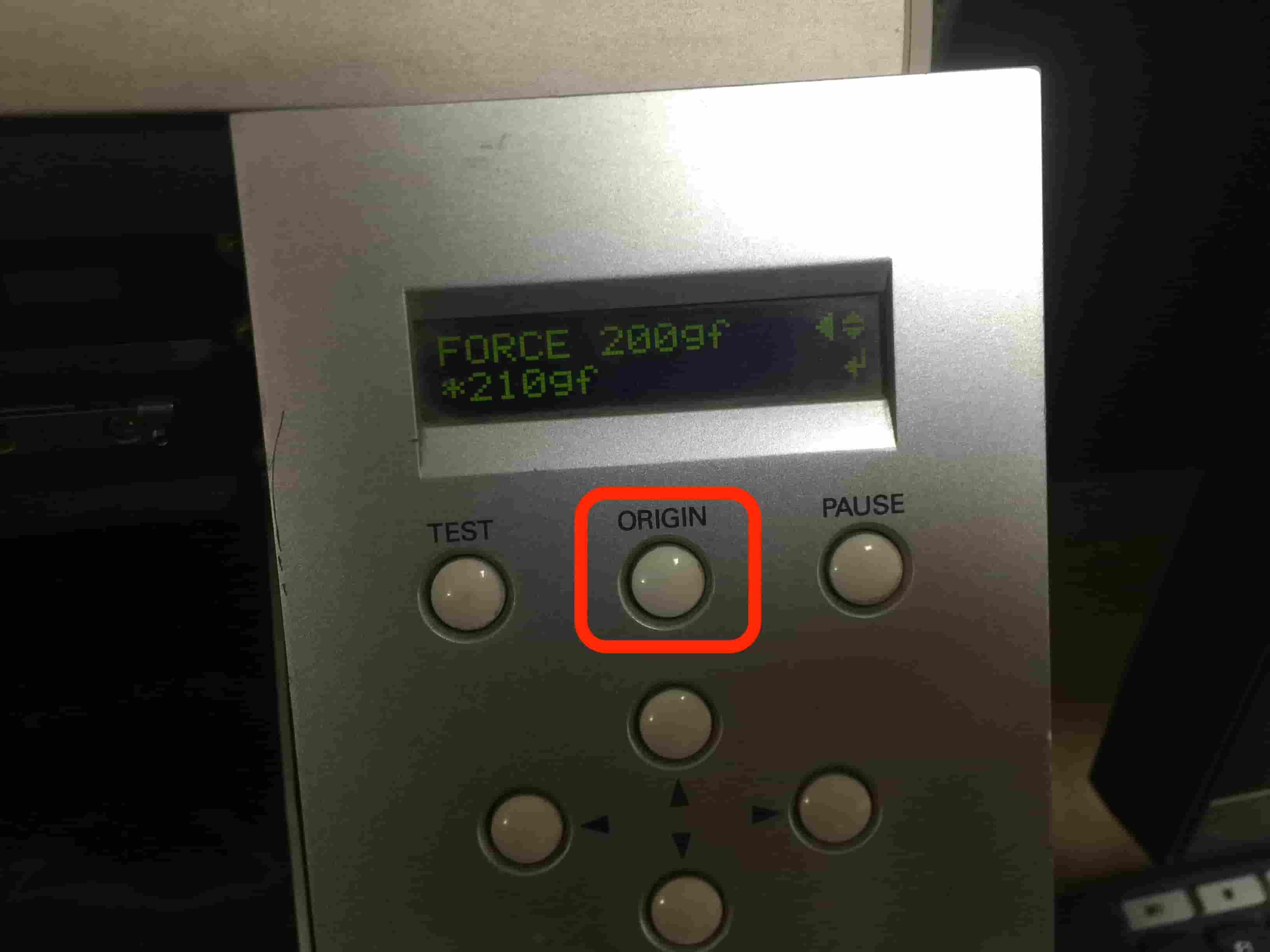
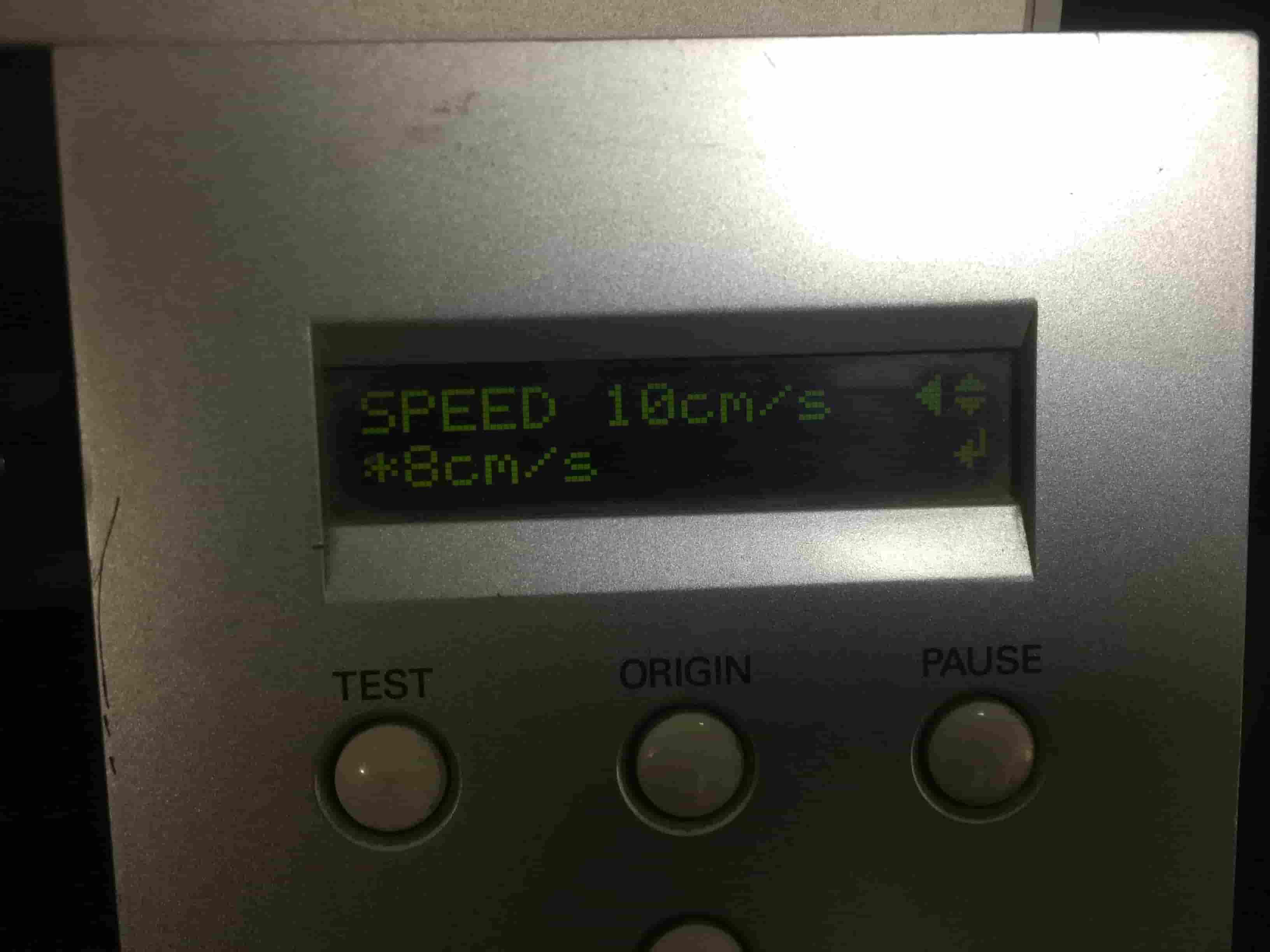
After some experiments with teh machine I fount that the speed 8mm/sec. is very good and make clean cut.
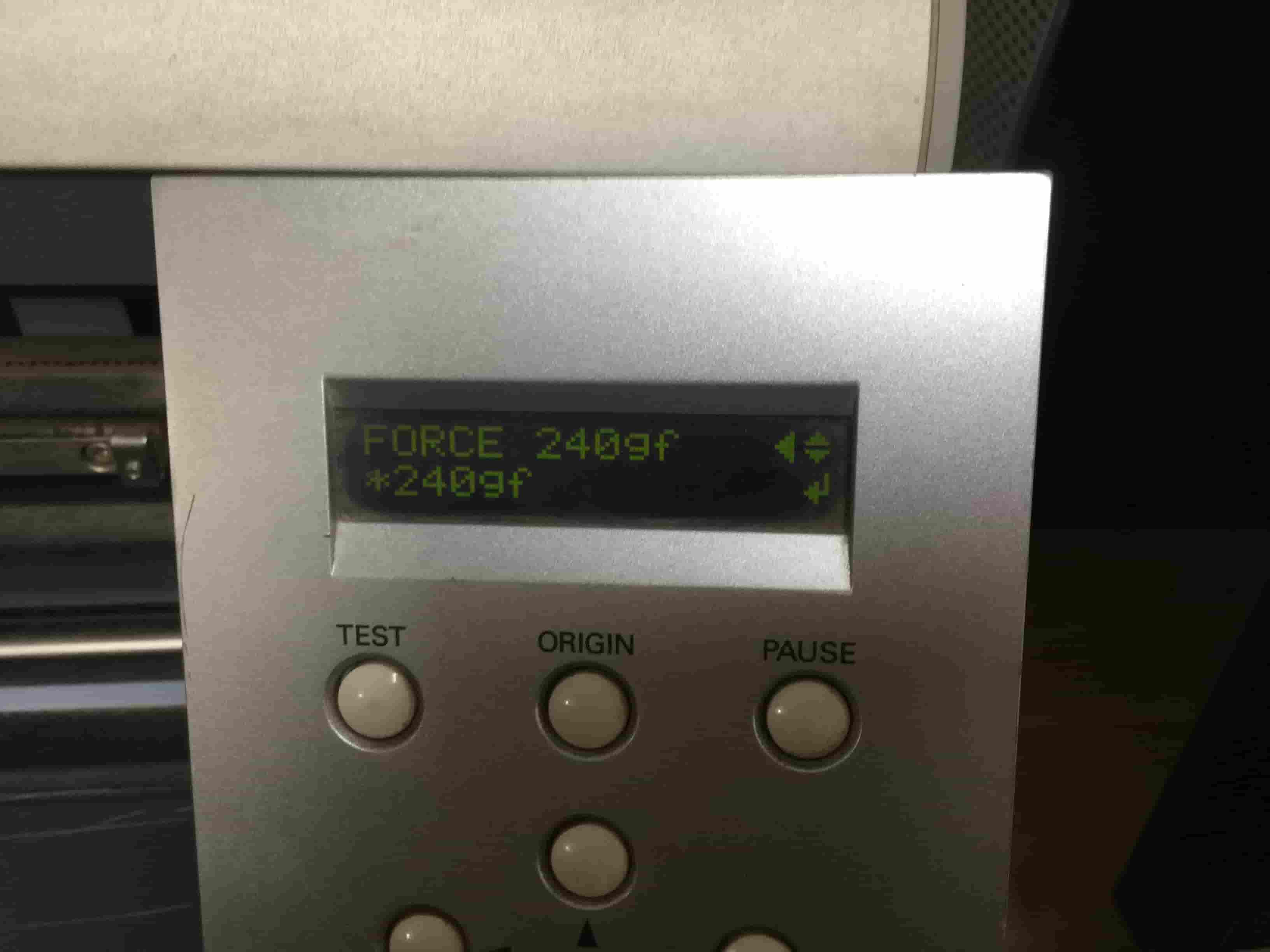
And, the force is 240 gf is very good.
After setting the force, speed, and setting the origin, from the toolbar, file -> cutting the machine will start cutting the material from the origin that you set before.
Then, I used tape to get all the cut parts out of the vinyl roll.
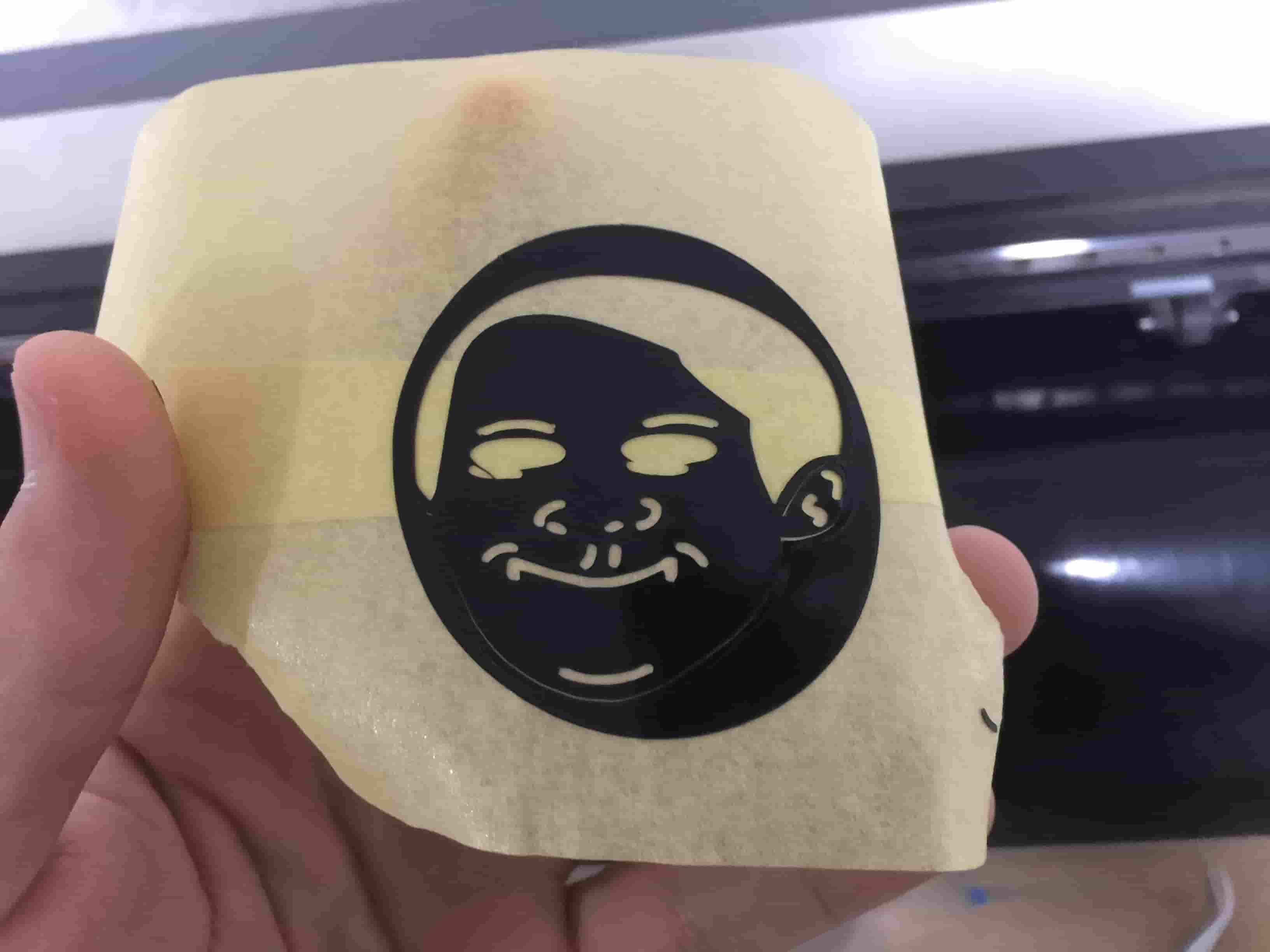
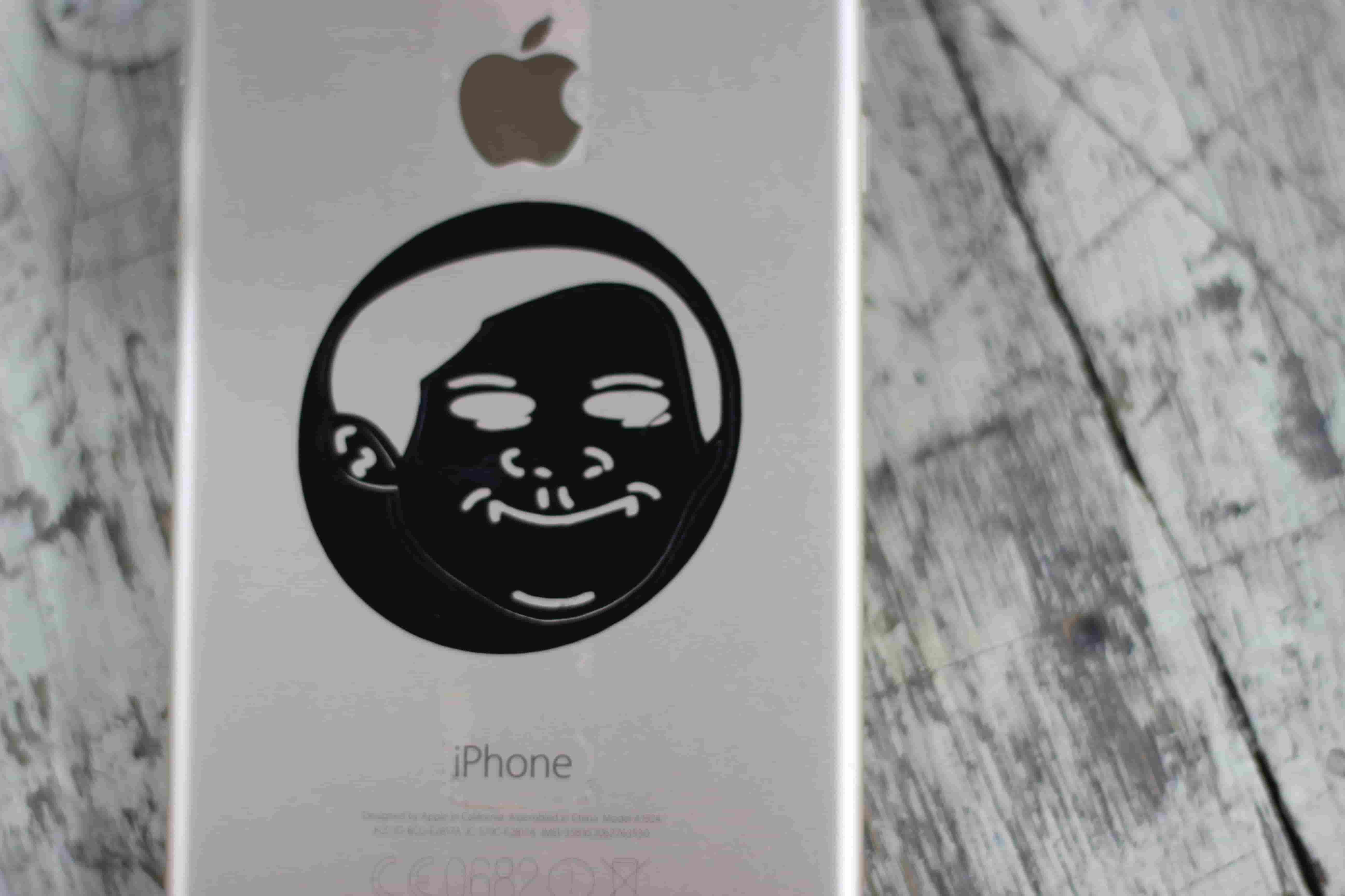
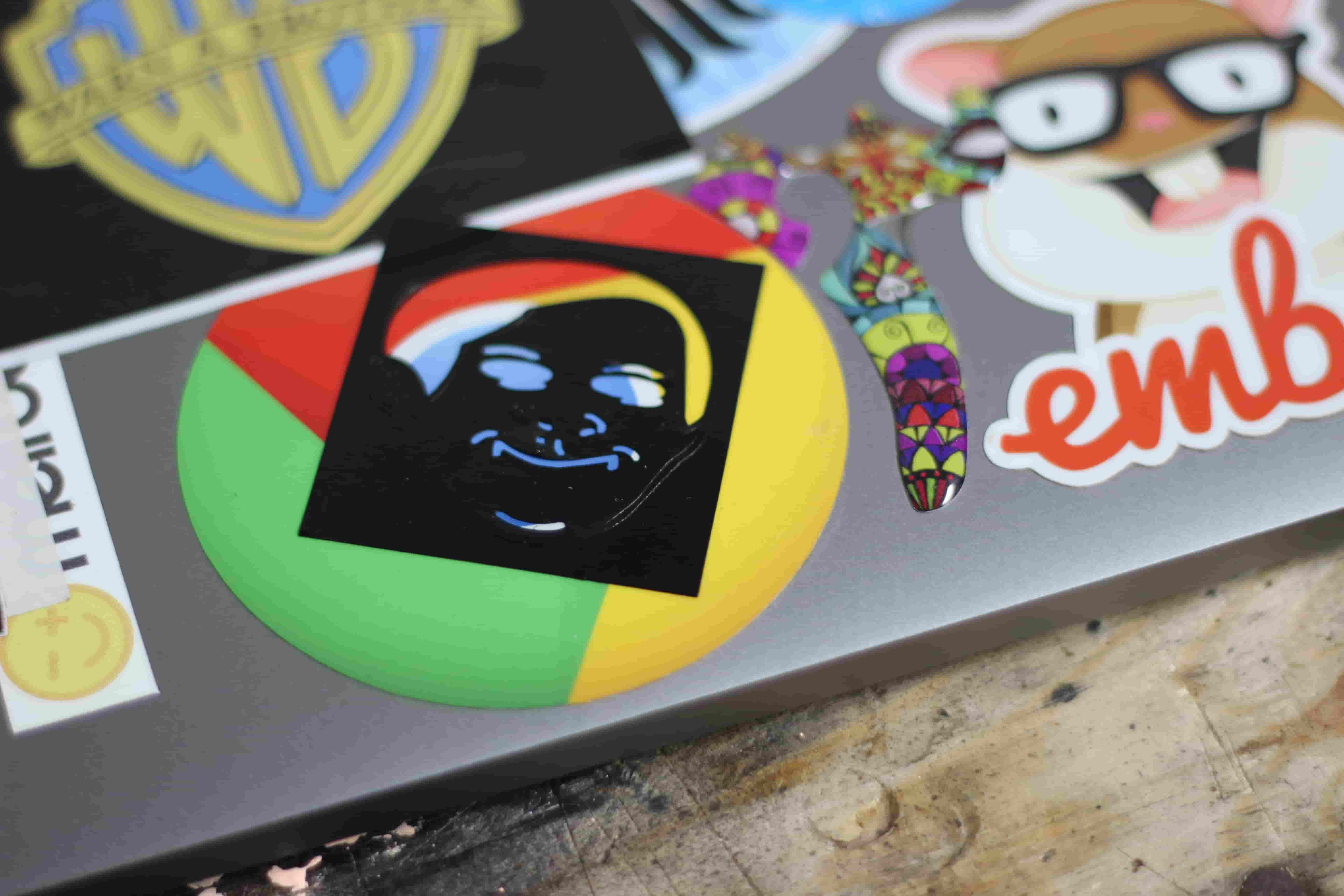
Then I repeated the same previous cutting process but on a different color to make that weird-looking sticker :D
I wanna thank My man Abulnaga for helping me in operating the machine

Vinyl Cutter Files Download
Useful Links:
- A good Living Hinge tutorial that I followed.
- MORN MT3050D Laser cutter Machine.
- Roland CAMM-1 Servo