Computer-Aided Design
What’s going on?
This week, we are working on some 3d modeling and 2d designing and CAD stuff. I decided to discover as many softwares as I can and not only stick to the softwares that I’m good at. This week I will discover:
- Photoshop for the raster 2D sketching.
- Inkscape for the Vector 2D sketching.
- Fusion360 for 3D modeling, animation and simulation.
- Xdesign for 3D modeling, animation and simulation.
Actually, I’m pretty excited about using Xdesign, I never used this software before. Inkscape I used it only once a few years ago, I have to dig deeper to see how this software works and get the most of it. I used Photoshop and Fusion360 before but I’m sure that I’m missing a lot of interesting stuff in these two softwares which I will try to find out in this assignment(I hope).
Some Important Concepts
What is the difference between Raster and vector?
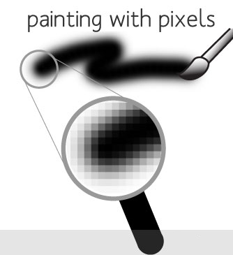
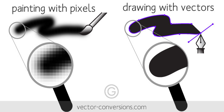
- Raster images are based on pixels, which is a dot containing color information, the more dots(pixels) your screen has the more quality you get. The same thing with images, let’s consider that you have an image which contains a specific number of pixels, the more you zoom in the less quality you get. Because, you are stretching the pixels not adding new ones.
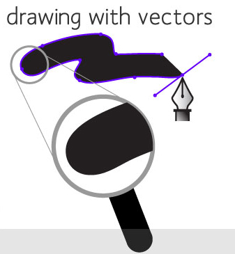
- Vector images are not based on pixels, they are based on some mathematical equations that result in a shape(image), vector images can get expanded as much as you want without losing quality. The mathematical equation changes itself to adapt at any scale.
Photoshop for the raster 2D sketching.
The most important part is Getting the concept of your design, from which part will you start?
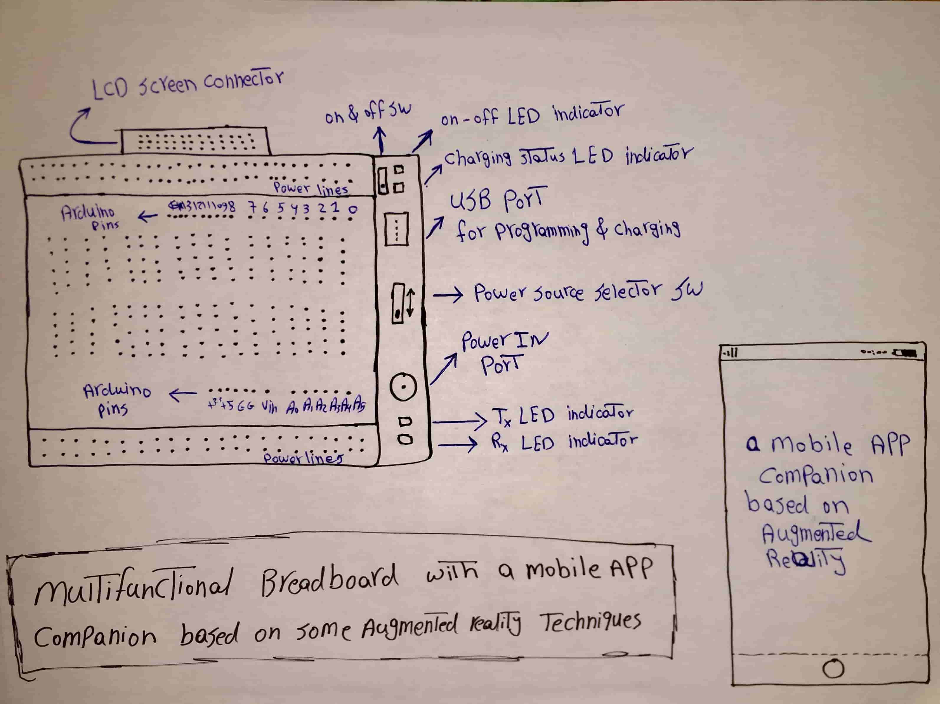
I already made a hand sketch for my final project idea at week one. So, I will use it as a guide to start working on my photoshop design.
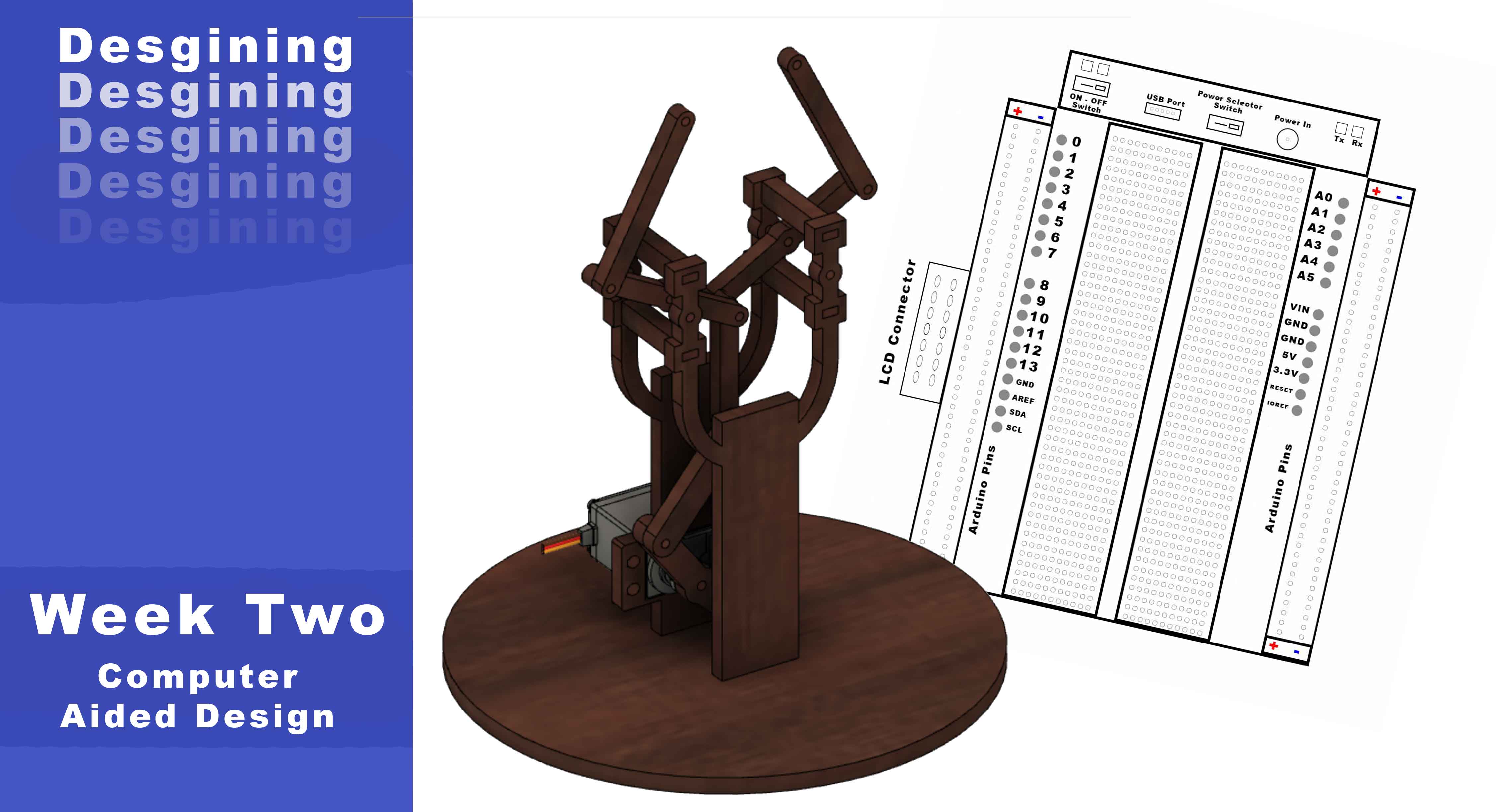
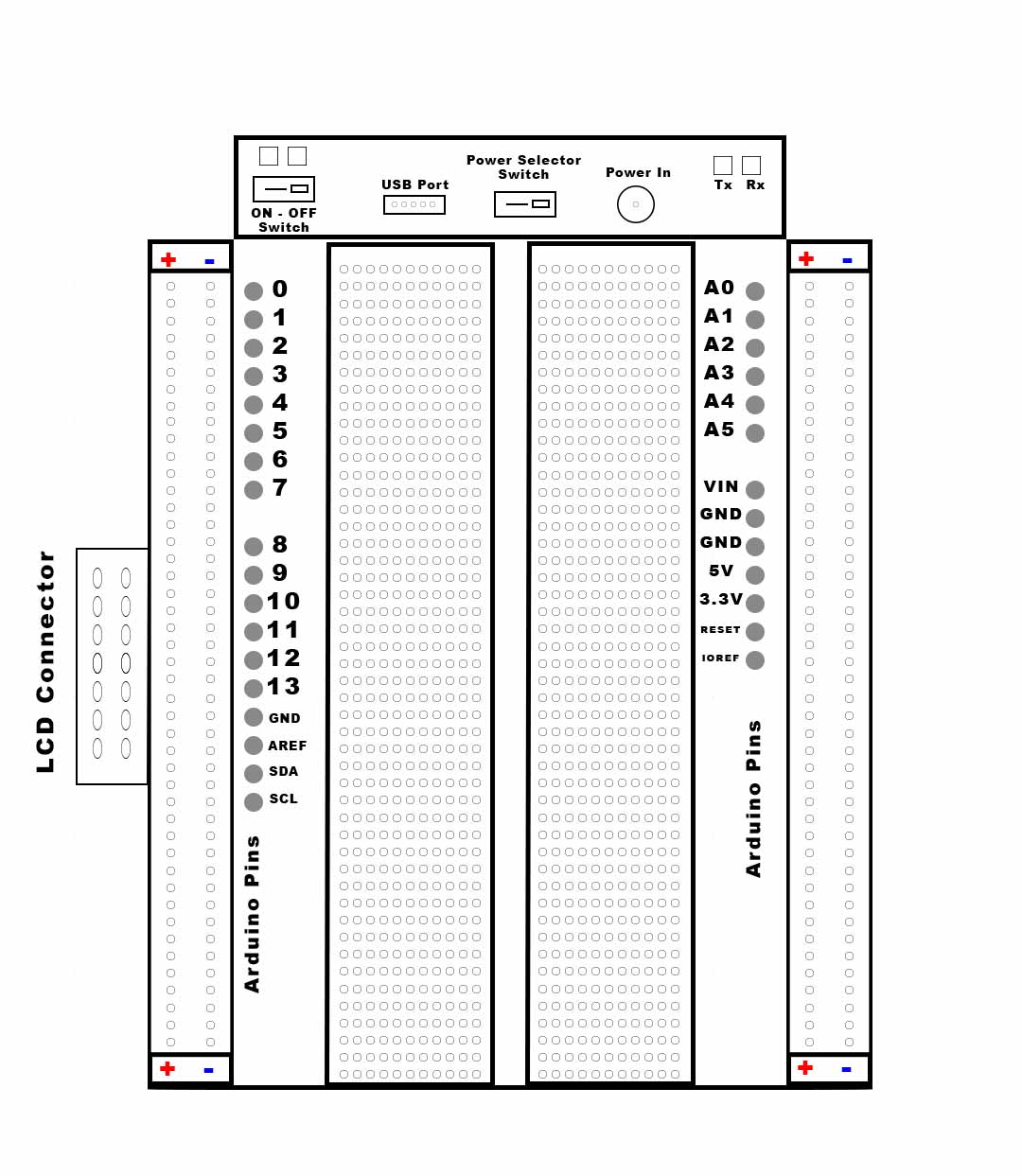
My final project idea is a multifunctional breadboard that can do some stuff besides connecting dots together. So, I guess it’s a good start point to design the breadboard outlines itself.
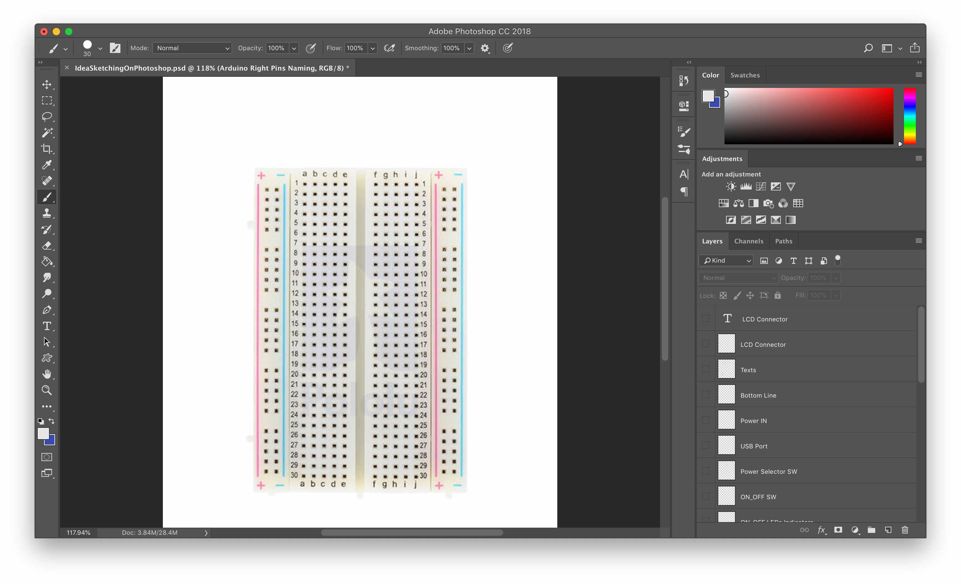
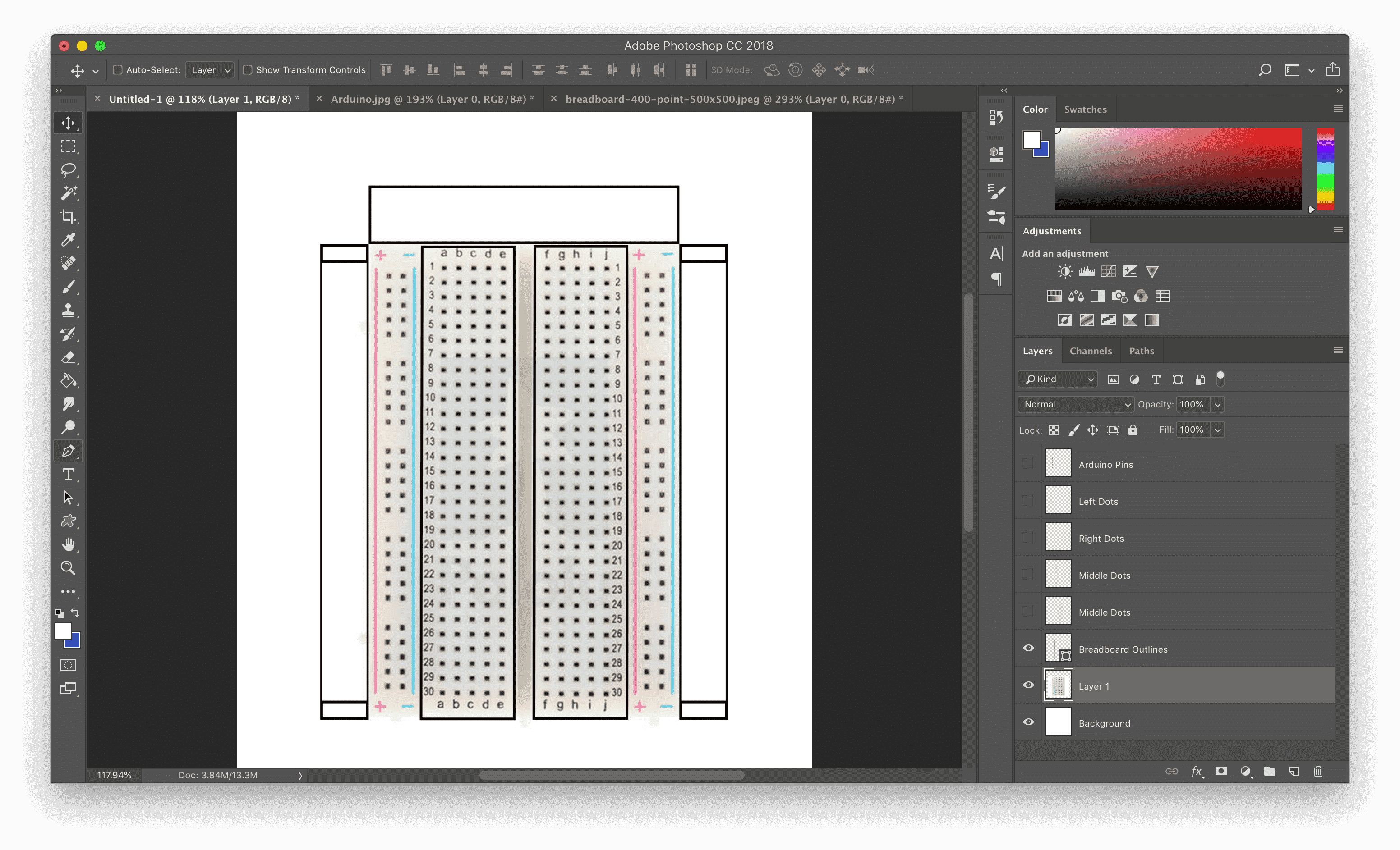
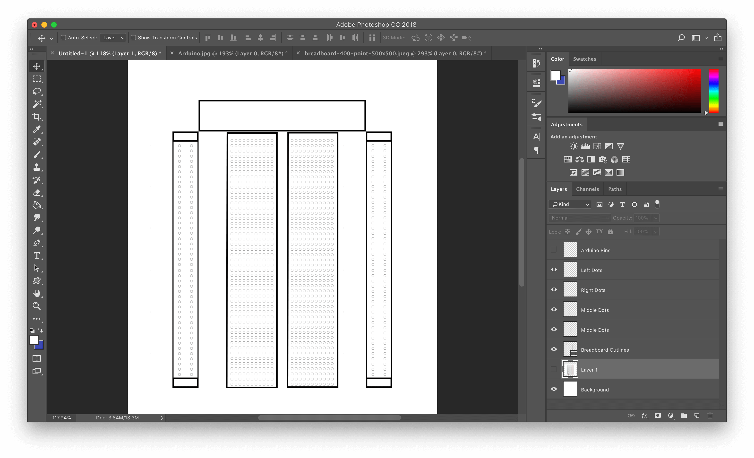
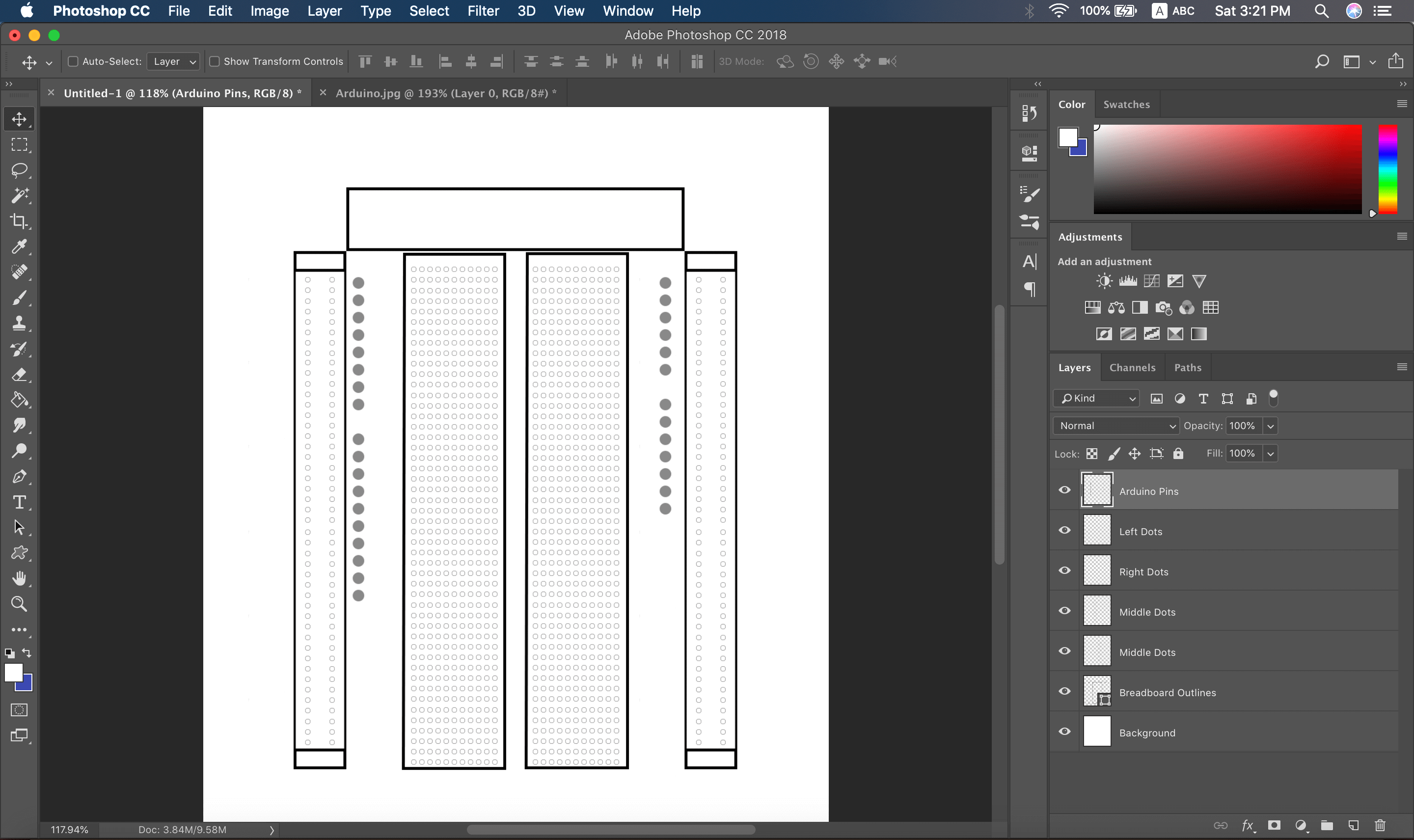
I downloaded a breadboard image and inserted it into my photoshop project. I used the image as a guide to get the breadboard outlines and structure with the proper aspect ratio.
Then I used the pen tool to trace the outlines of the breadboard.
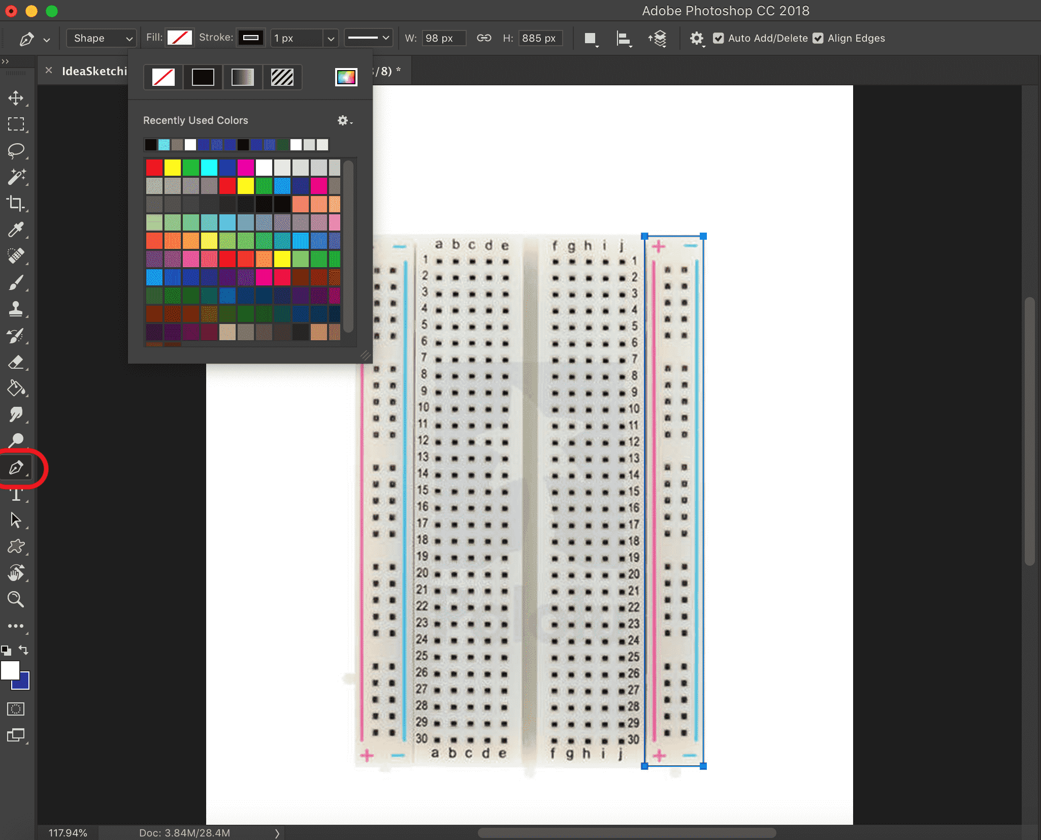
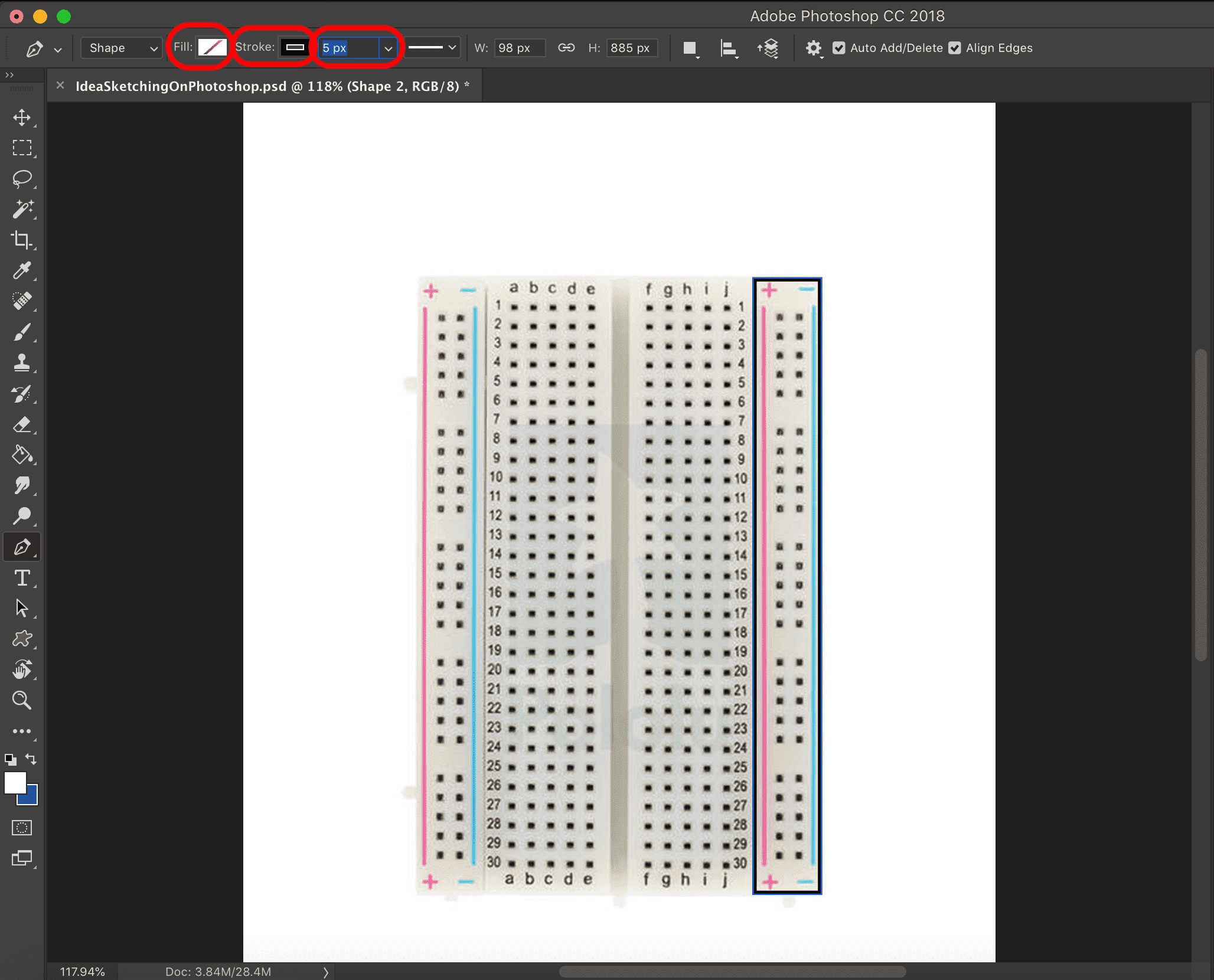
I used the pen tool to draw a path around the right hand side power rail, then set the fill to transparent, the stroke to black, and the stroke size to 5px.
After tracing the outlines of the breadboard, I got that shape (very breadboardy!).
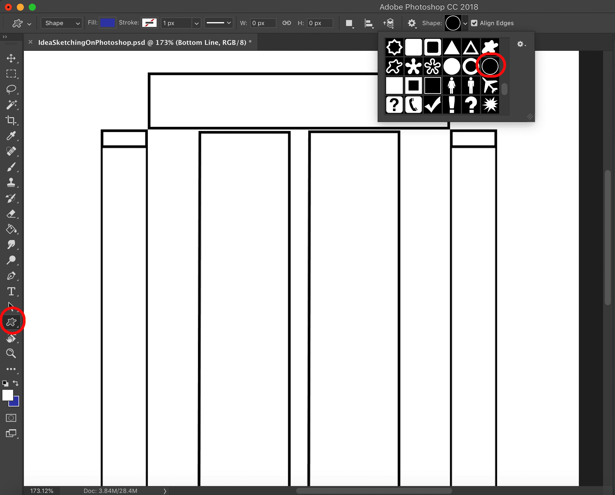
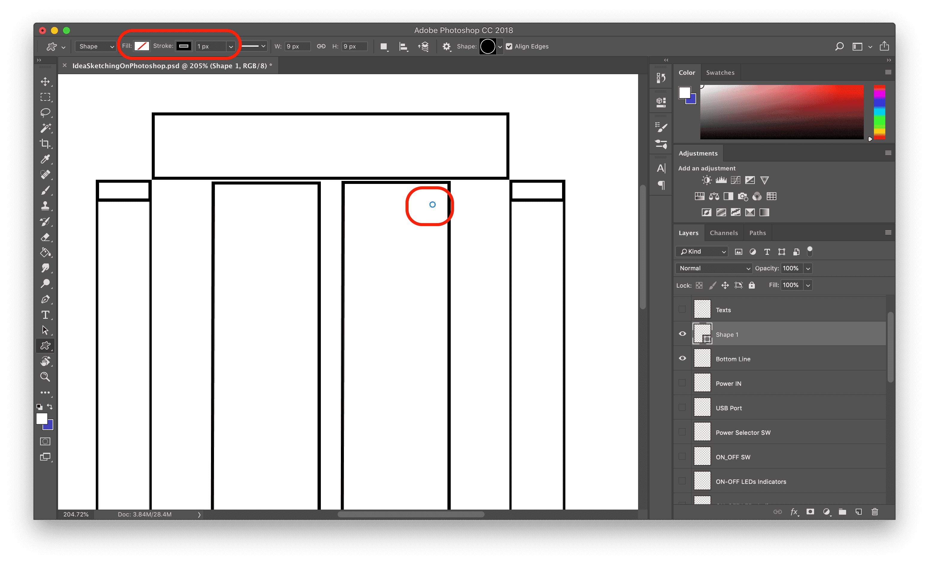
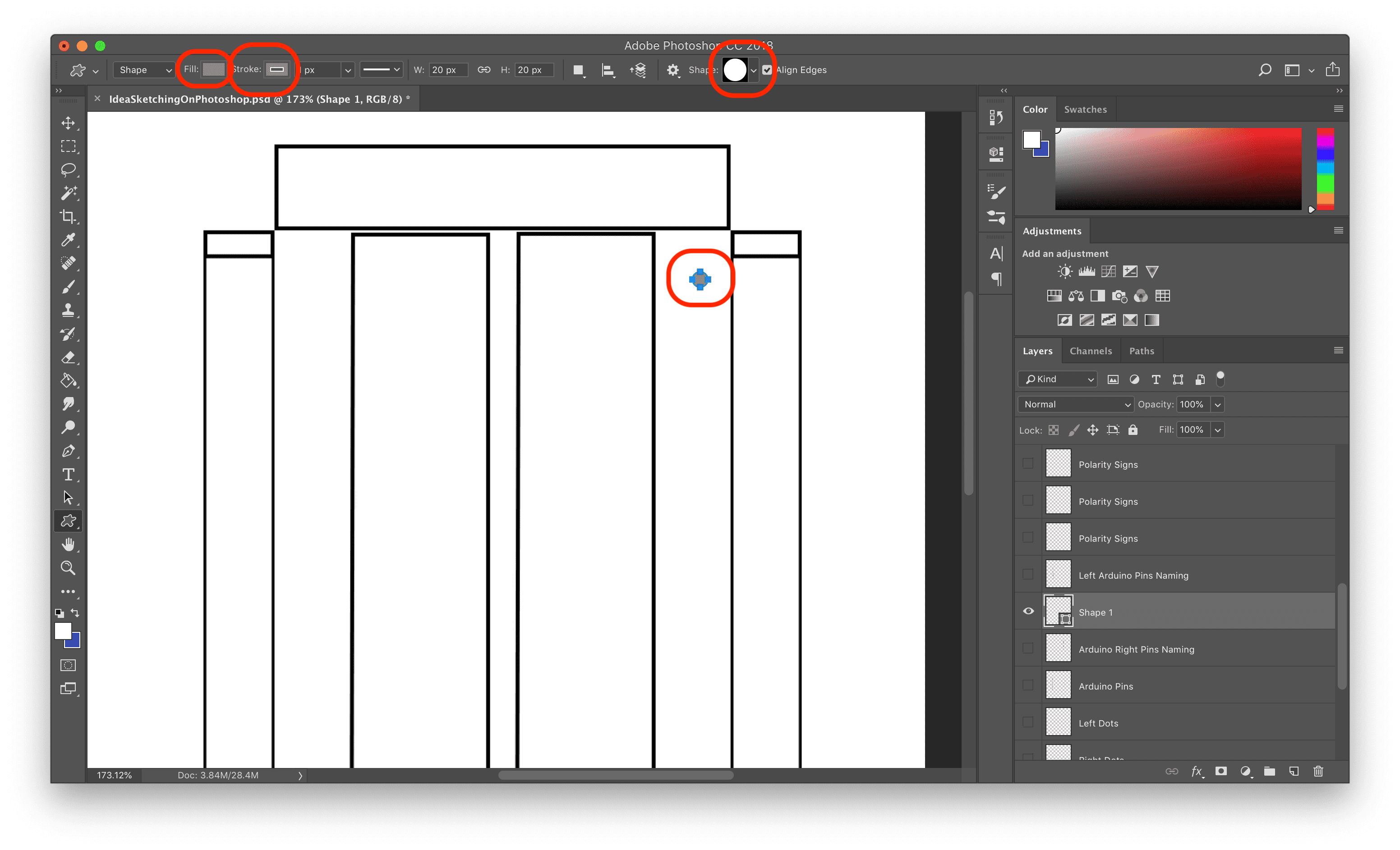
To make the breadboard connectors, I used the shape tool to draw a small circle representing a single pin connector.
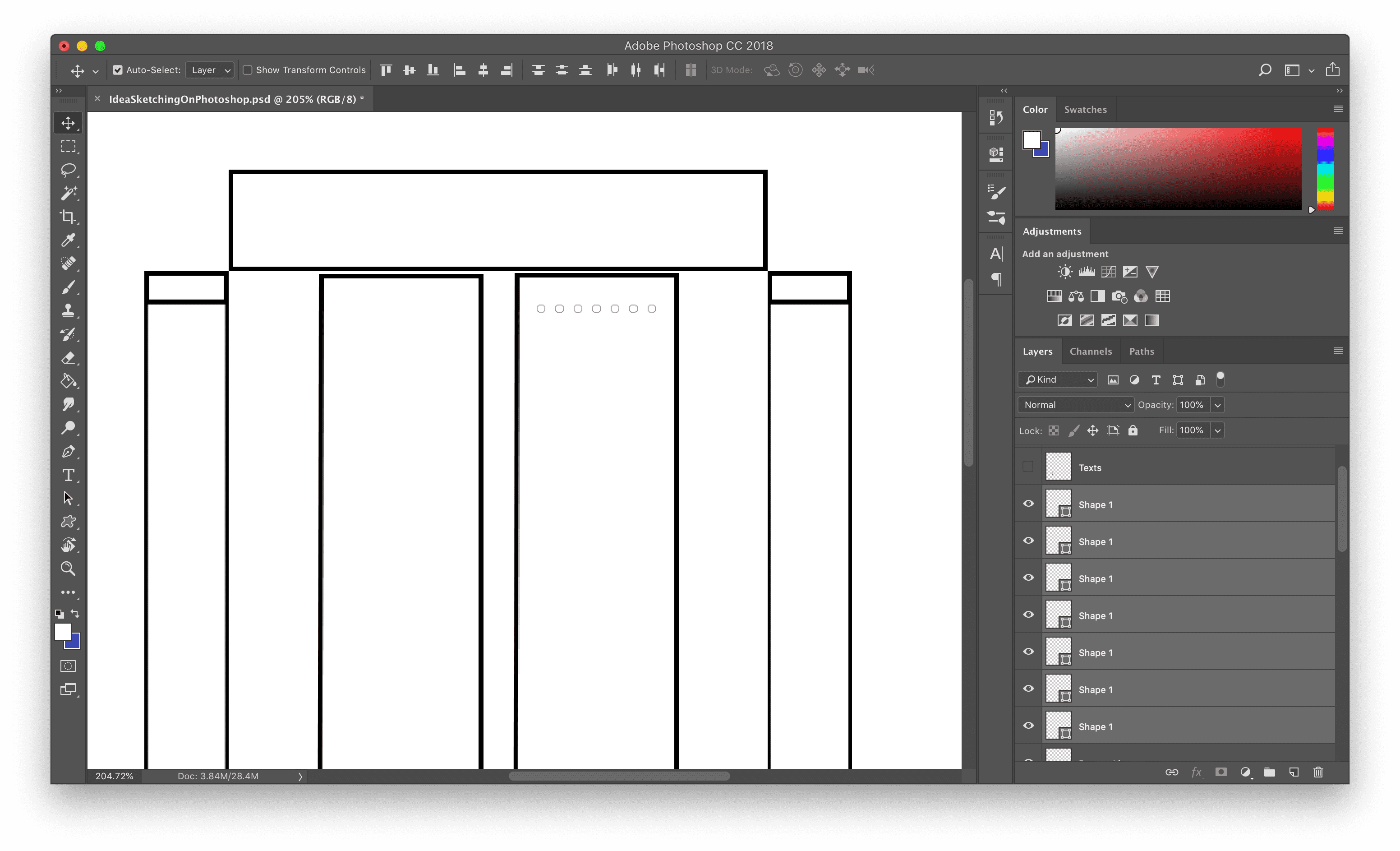
Then I copied this circle to make a single line of circles.
Then I copied that line of circles many times to make that much of circles.

I copied that whole side. to make the breadboard left side connectors.

With the same method I made the right and the left power rails.

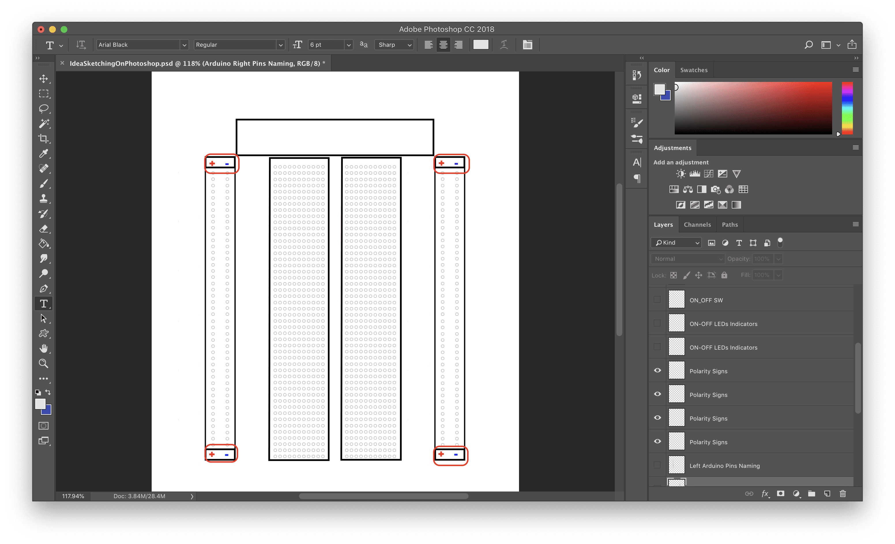
Then I used the Text tool to make the polarity signs, and changes it's color to red and blue.
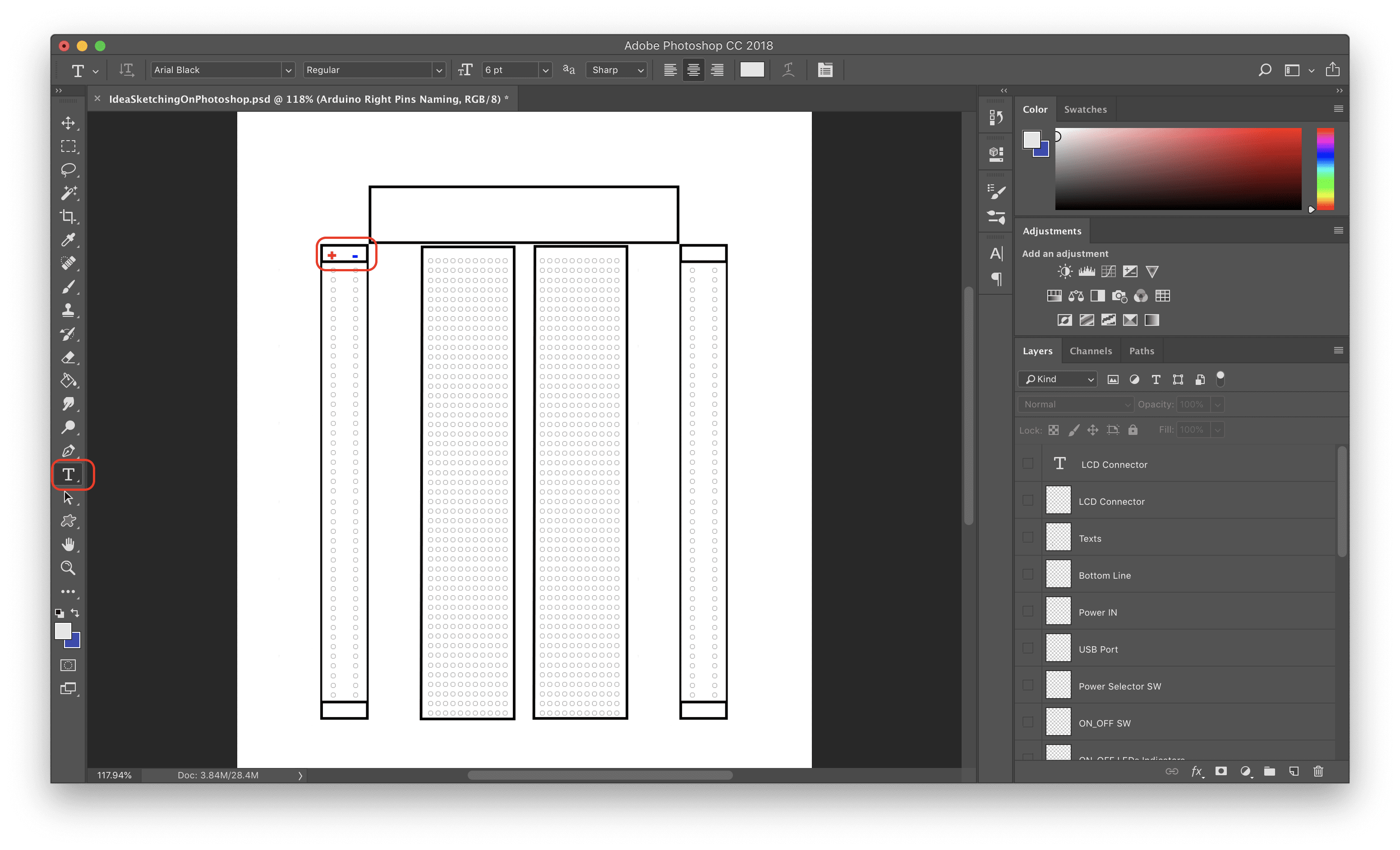
I repeated that another three times to make it at the four sides of the breadboard.
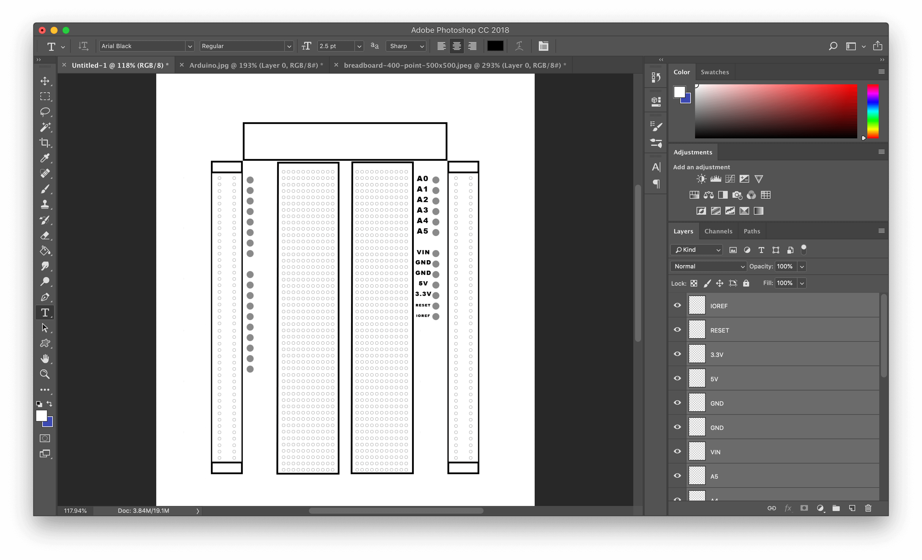
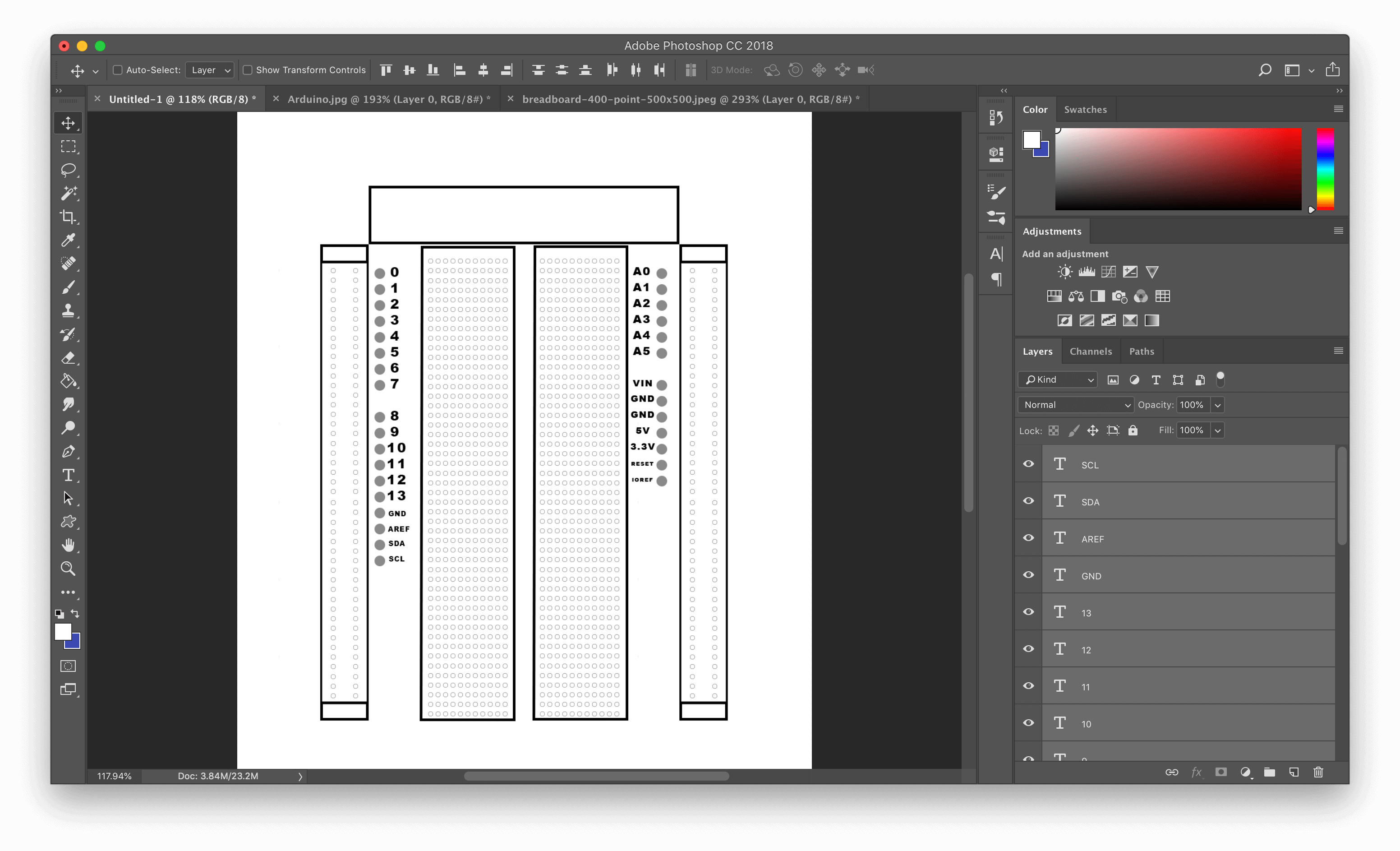
I used the shape tool again to make the Arduino GPIO pins. This time I selected a solid circle shape. Then I changed the fill and the stroke color to grey.
I copied this circle many times to make all the Arduino GPIO pins.
I used the Text tool to put the naming infron tof each connector.
Then I used the Pen tool again to make these switches and led indicators. And that’s it!
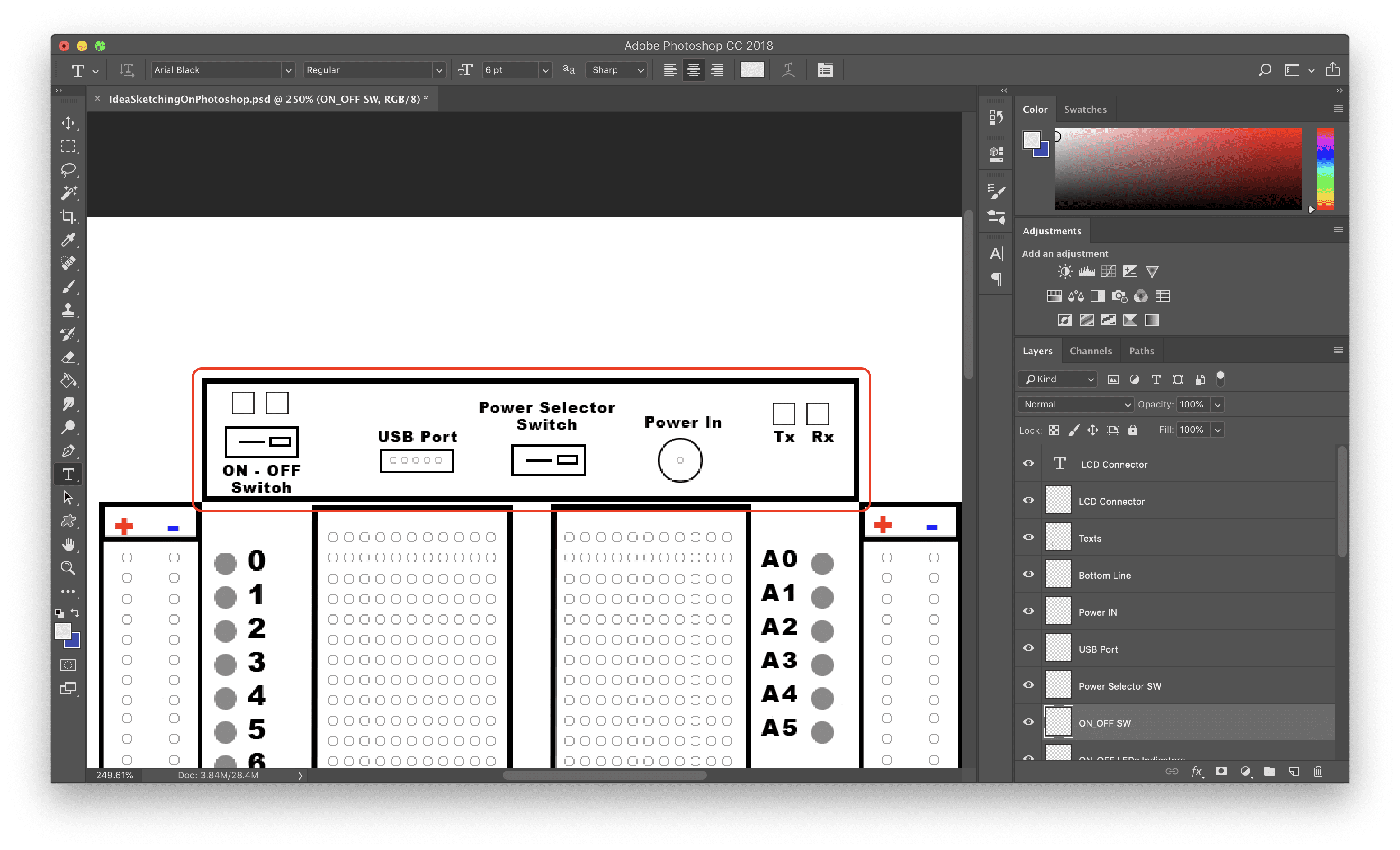
Theeeeeee Multifunctional breadboard, Tada!
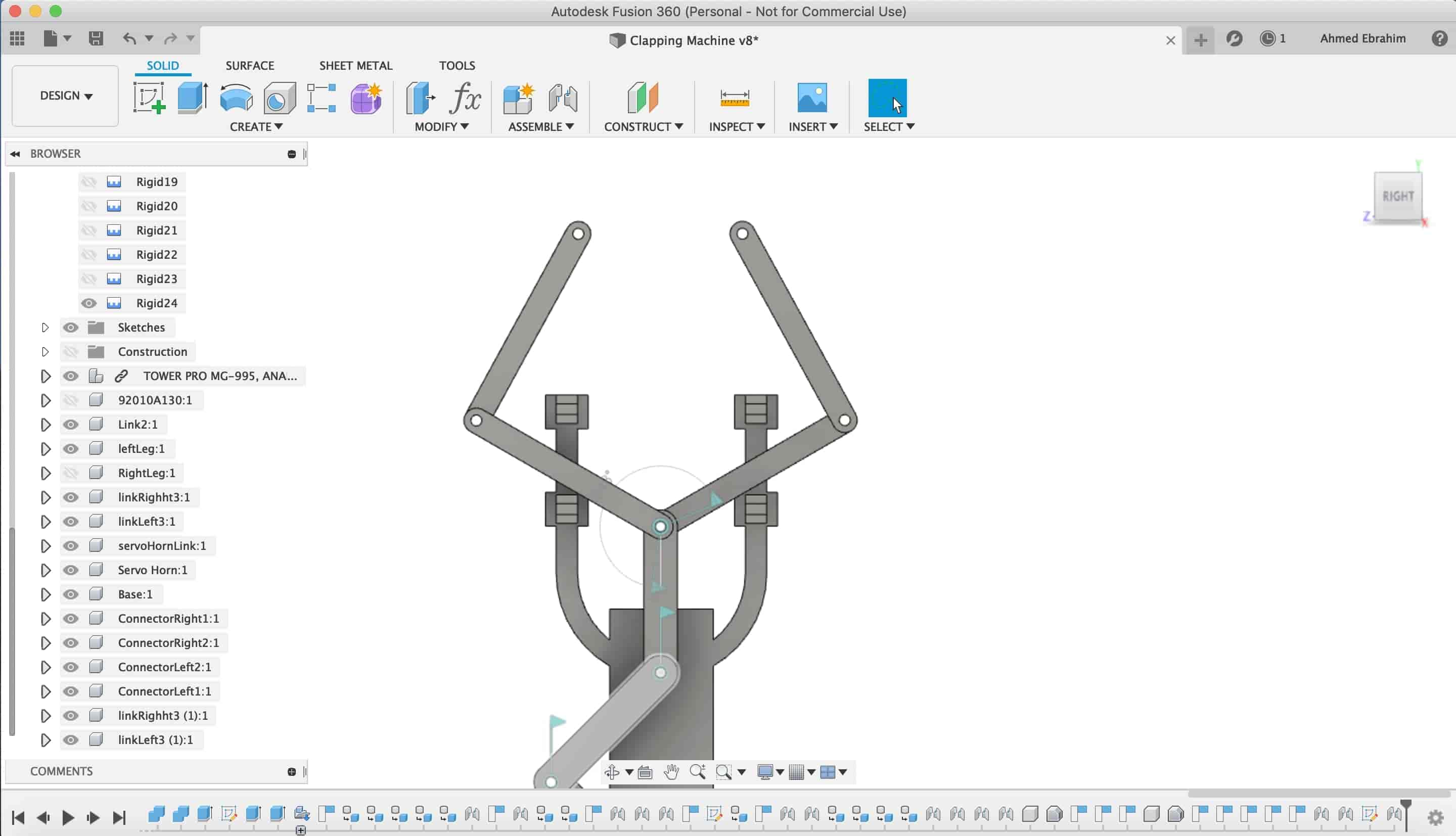
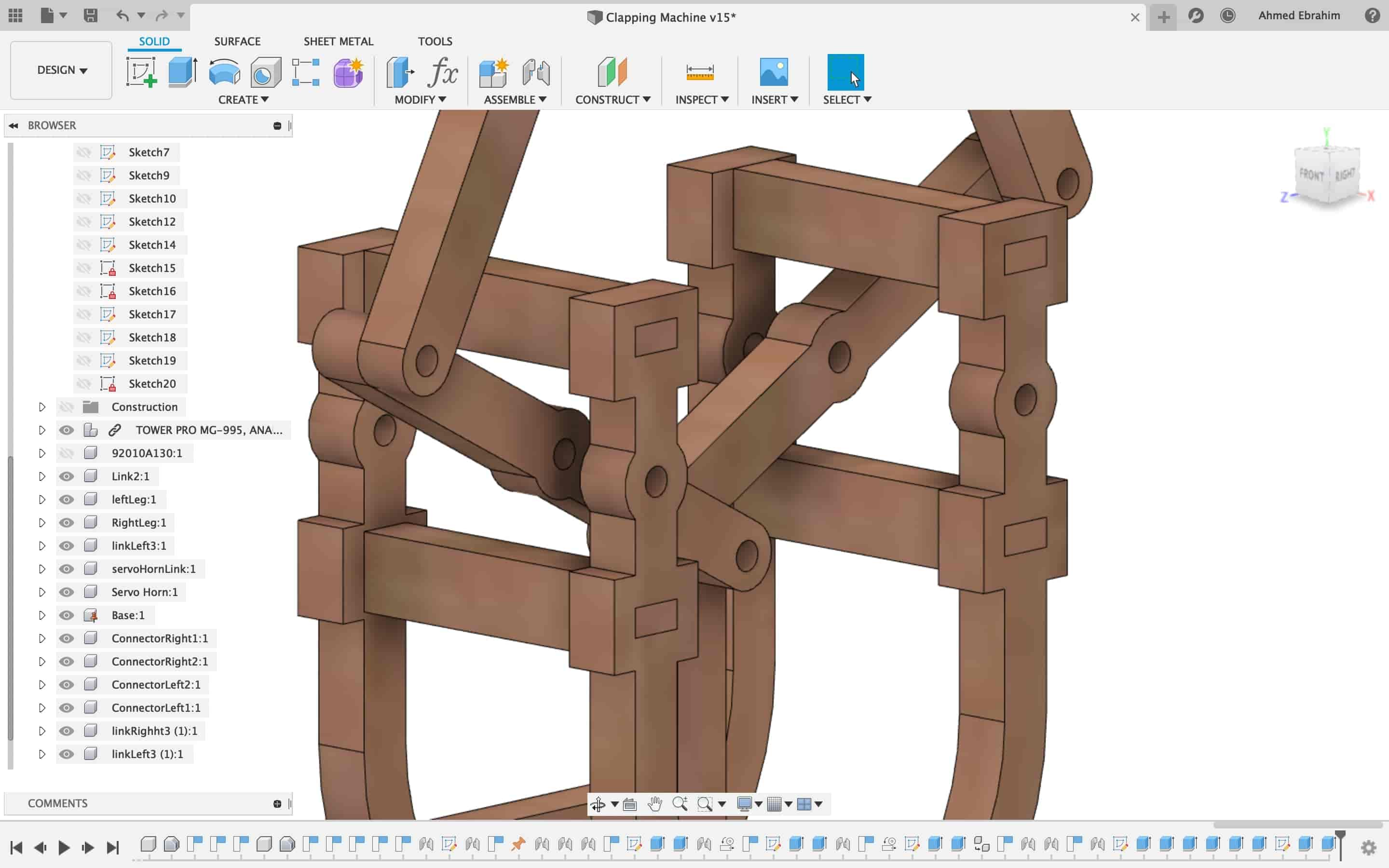
Fusion360 3d Modeling.
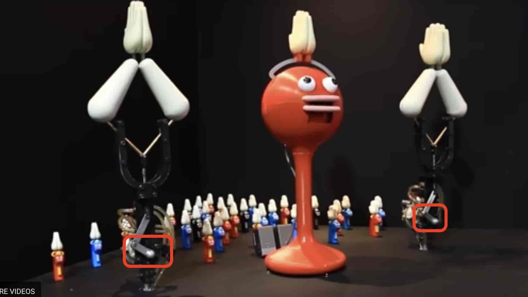
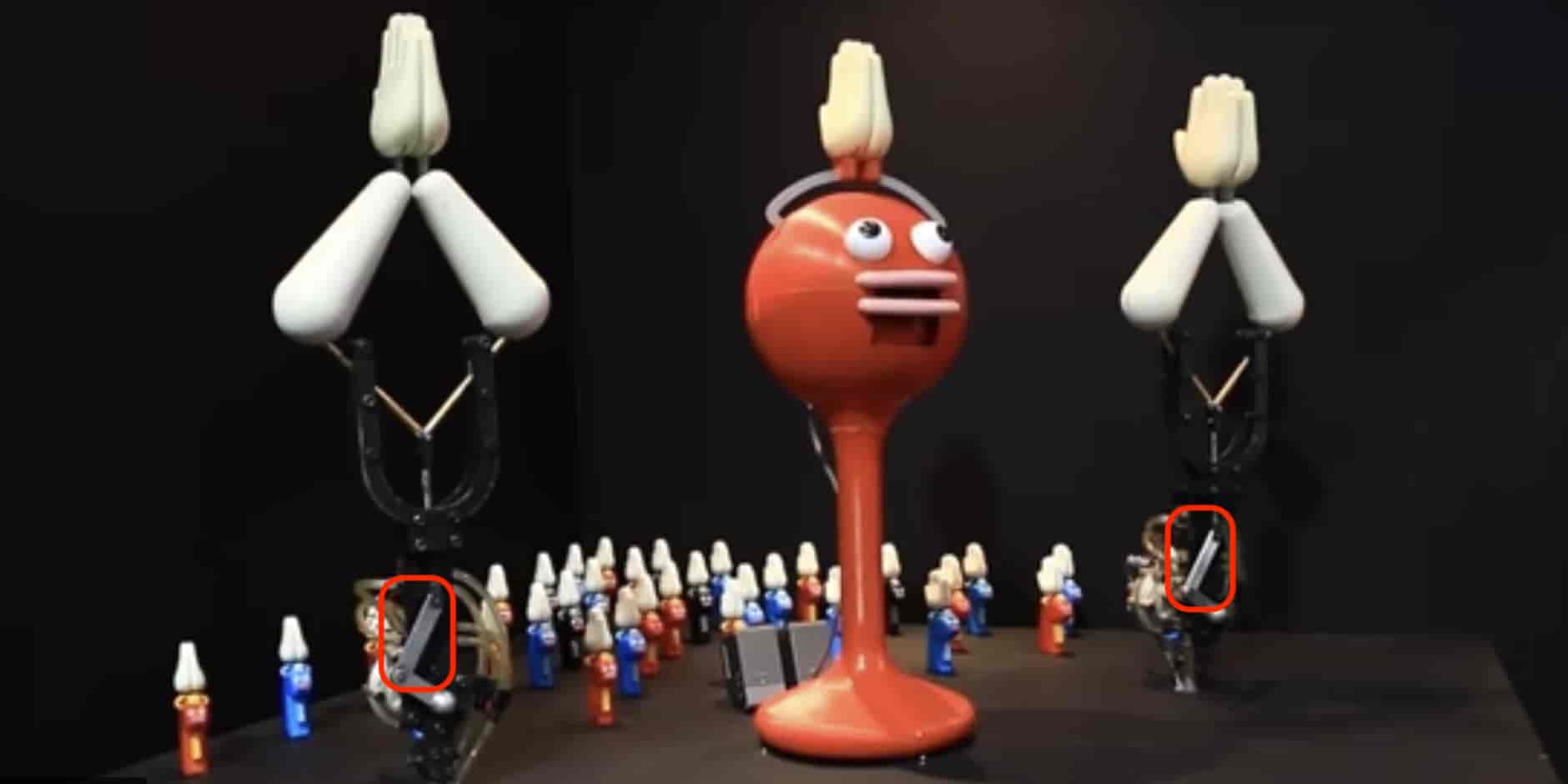
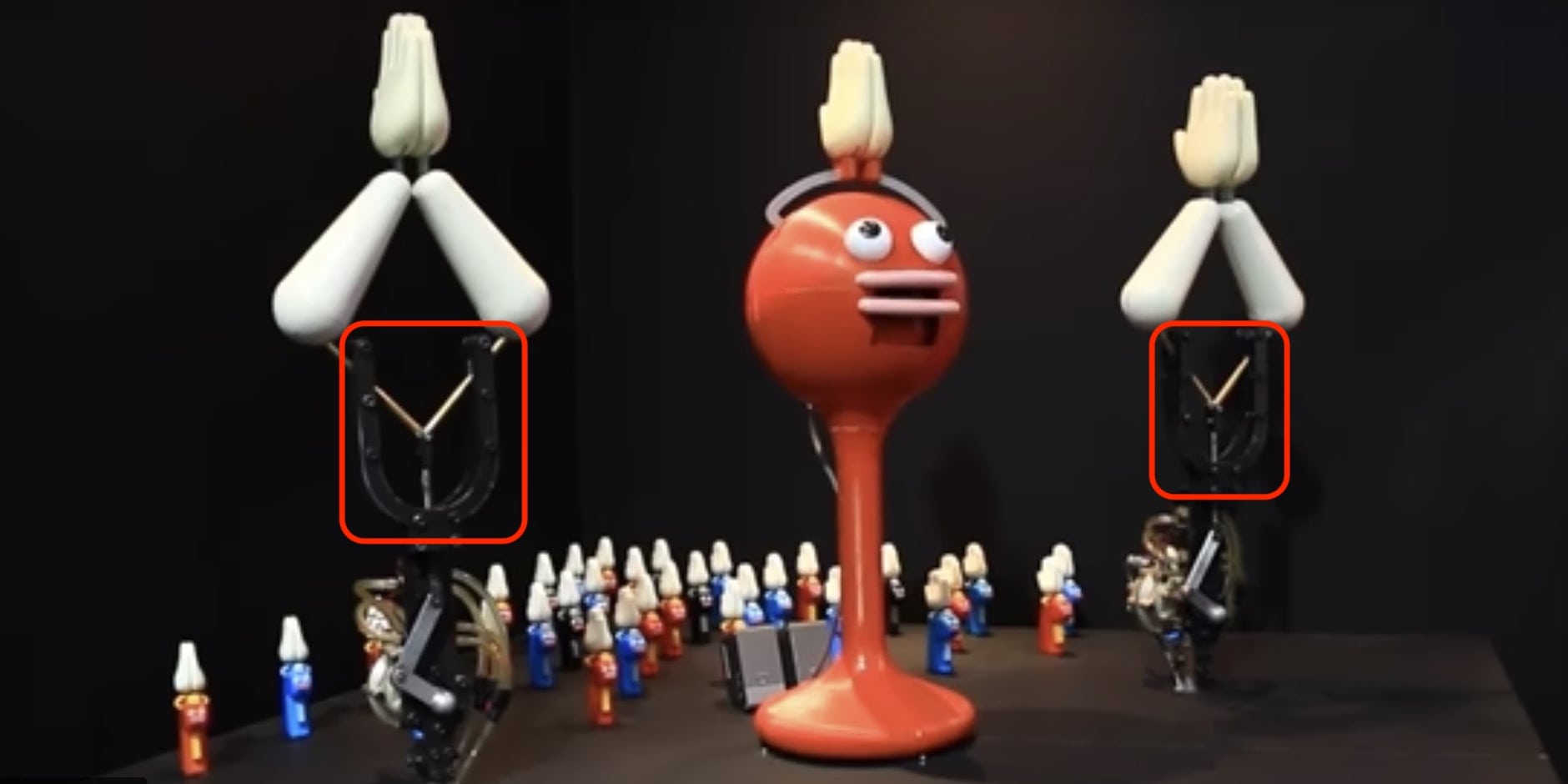
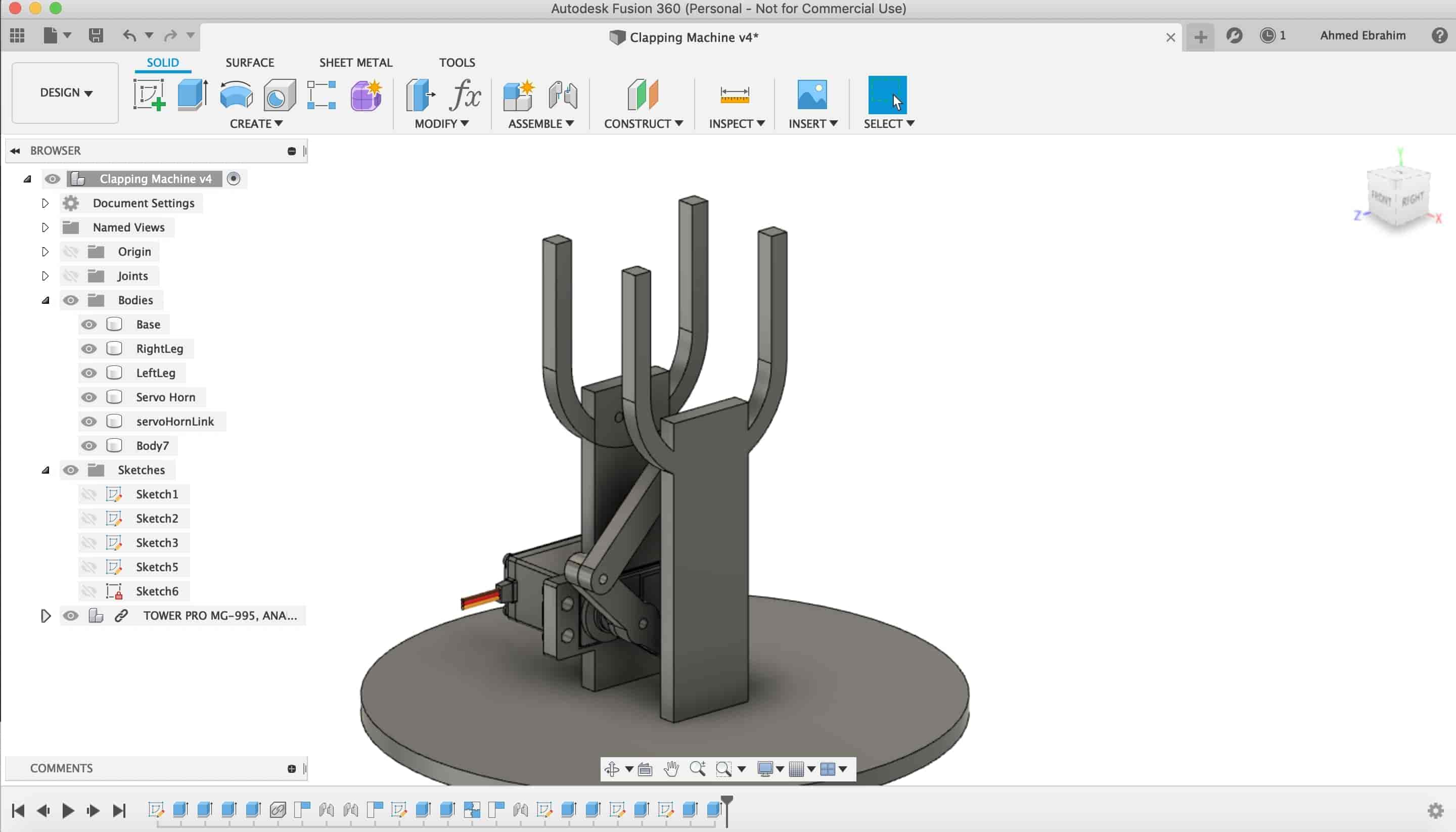
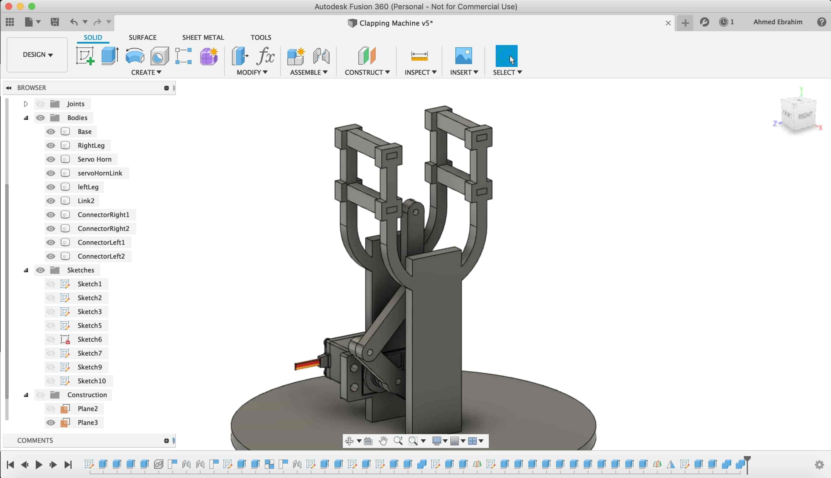
Five days ago, a saw a video for a robot that interacts with people by just clapping. Man I like that! Even I talked with my friend Ahmed Saeed that I want to make one and bring it with me to any session or talk I give and clap to anything I say :D
The mechansim contains:
- a base that holds all the body
- an actuator that responsible for moving that joints and links to make that hand claps. I will use servo motor for this job.
- Some joints and links that translates the movement of the motor to the hands.
- a front & back faces that kinda hide the internal mechanism.
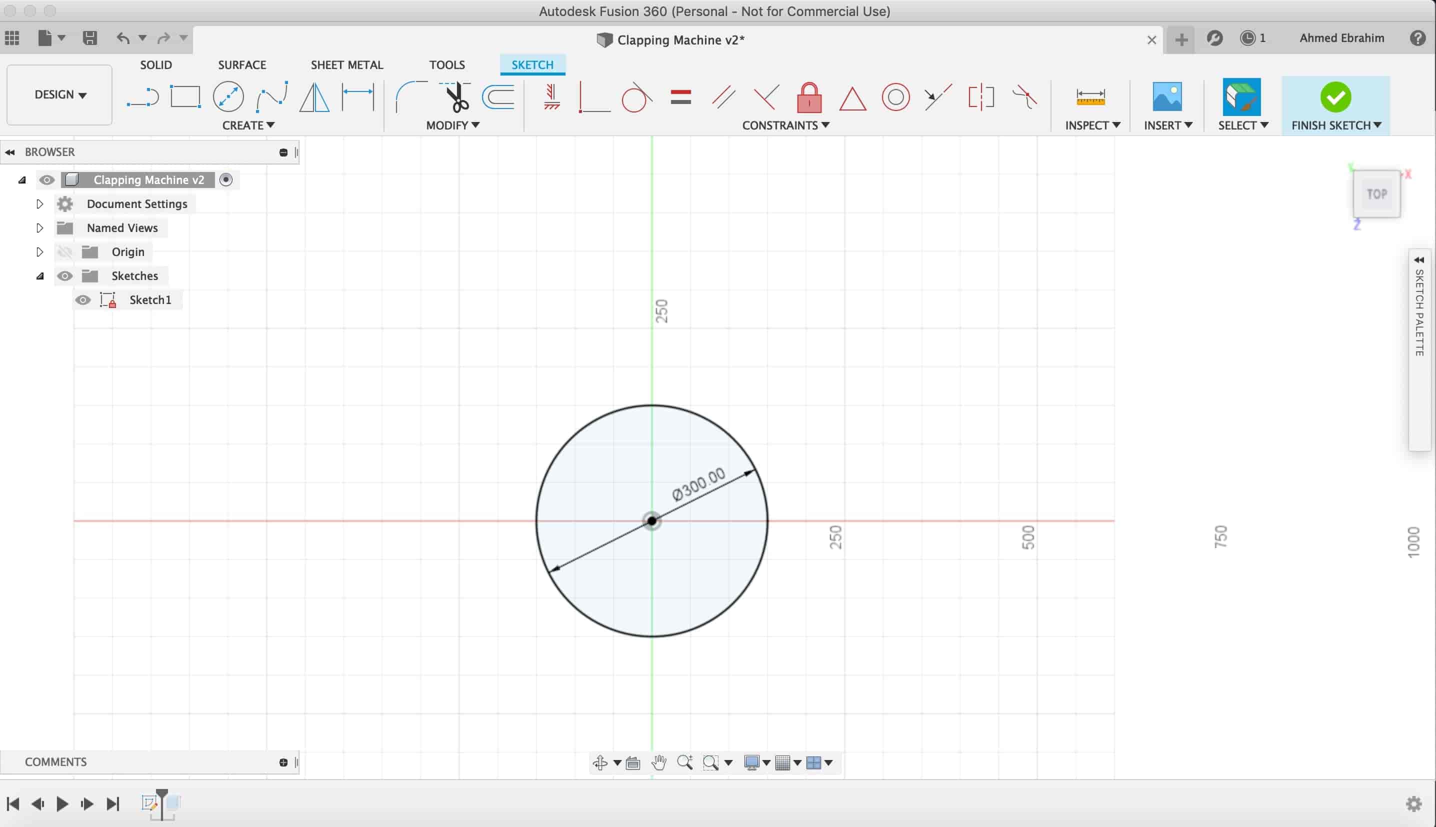
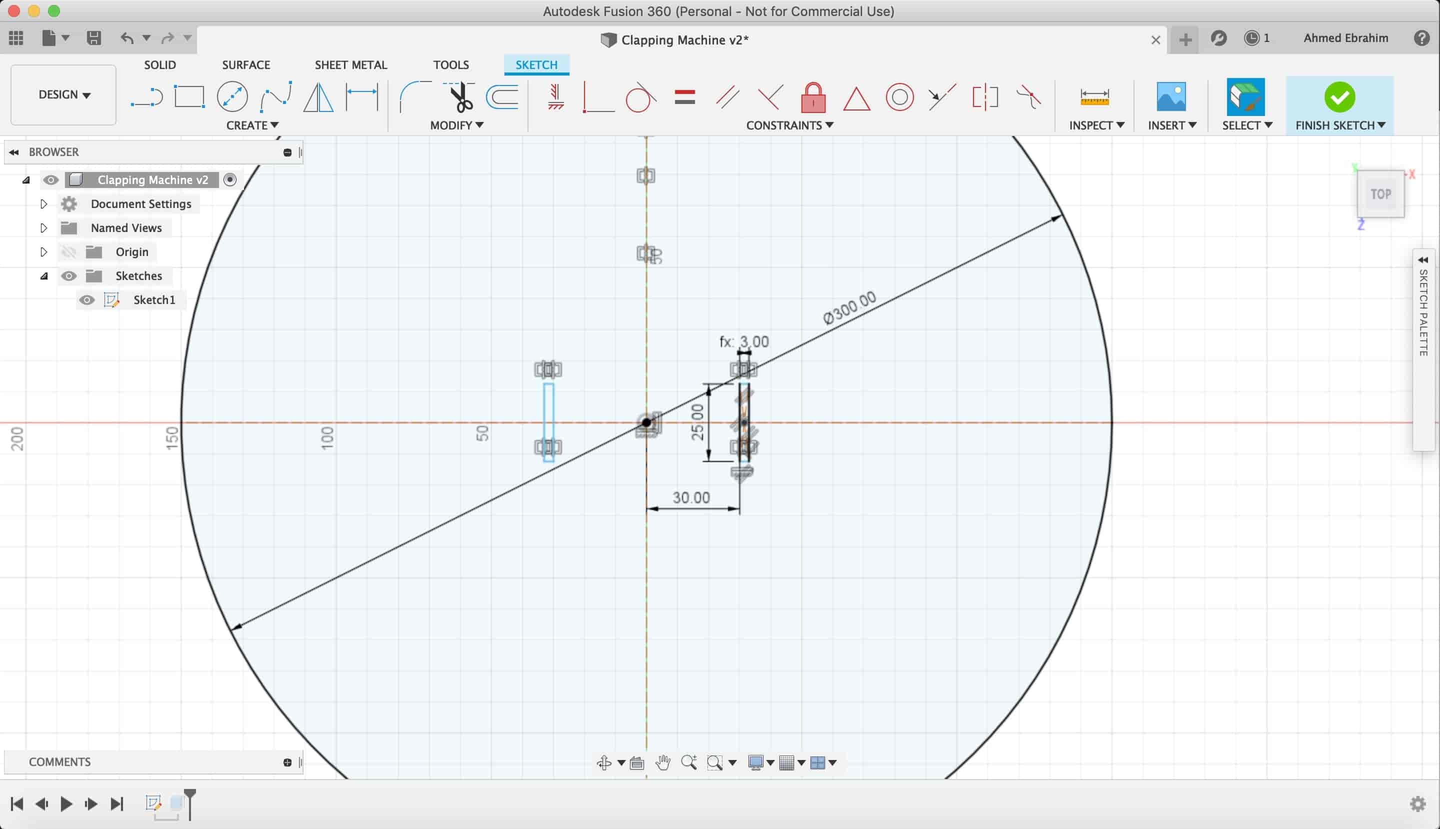
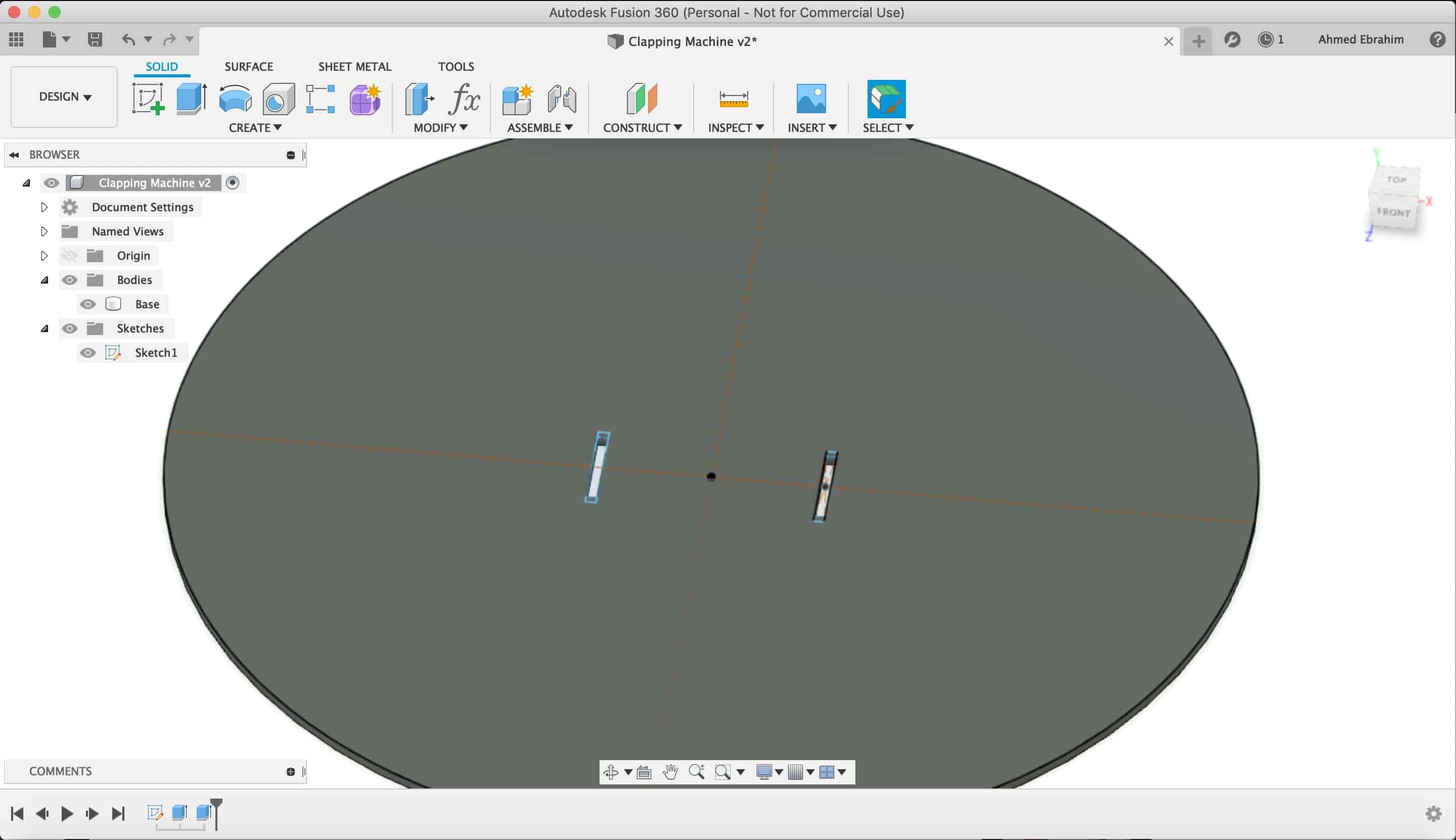
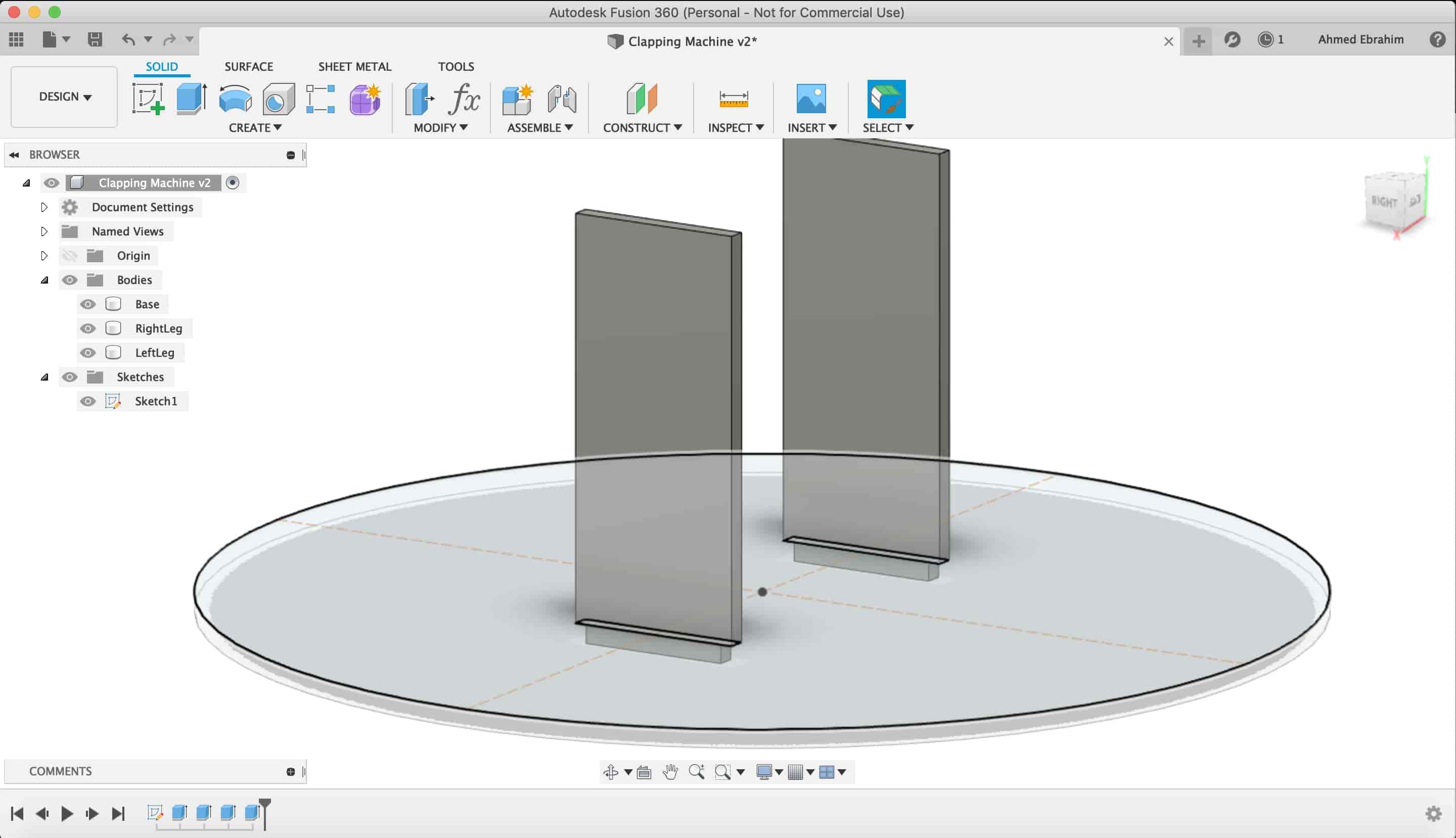
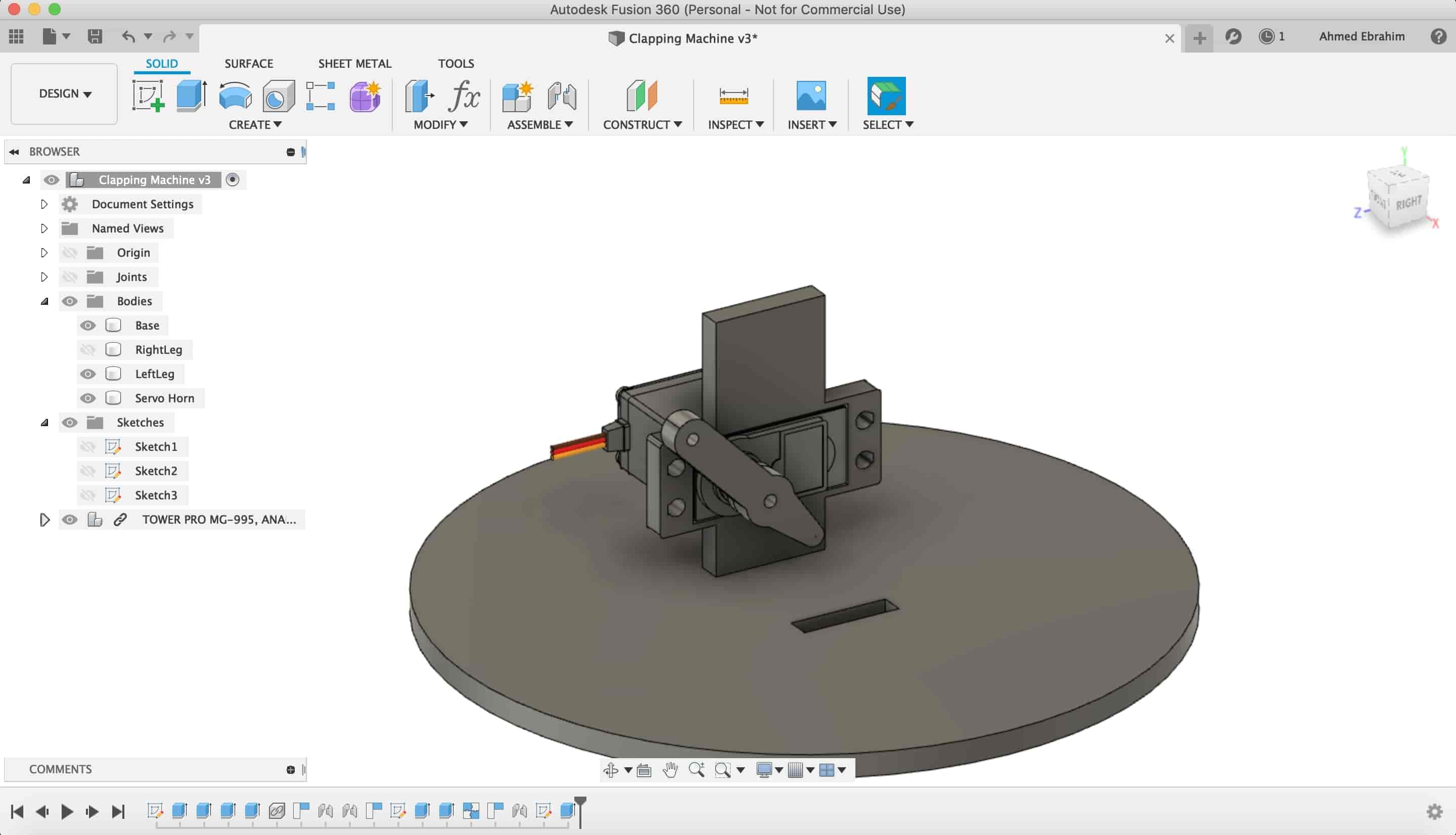
I used Fusion360 from Autodest to start desigining my clapping robot, I started with making a sketch to draw the circular base of the robot. It has two fittings to mount some things on it, you will see that later.
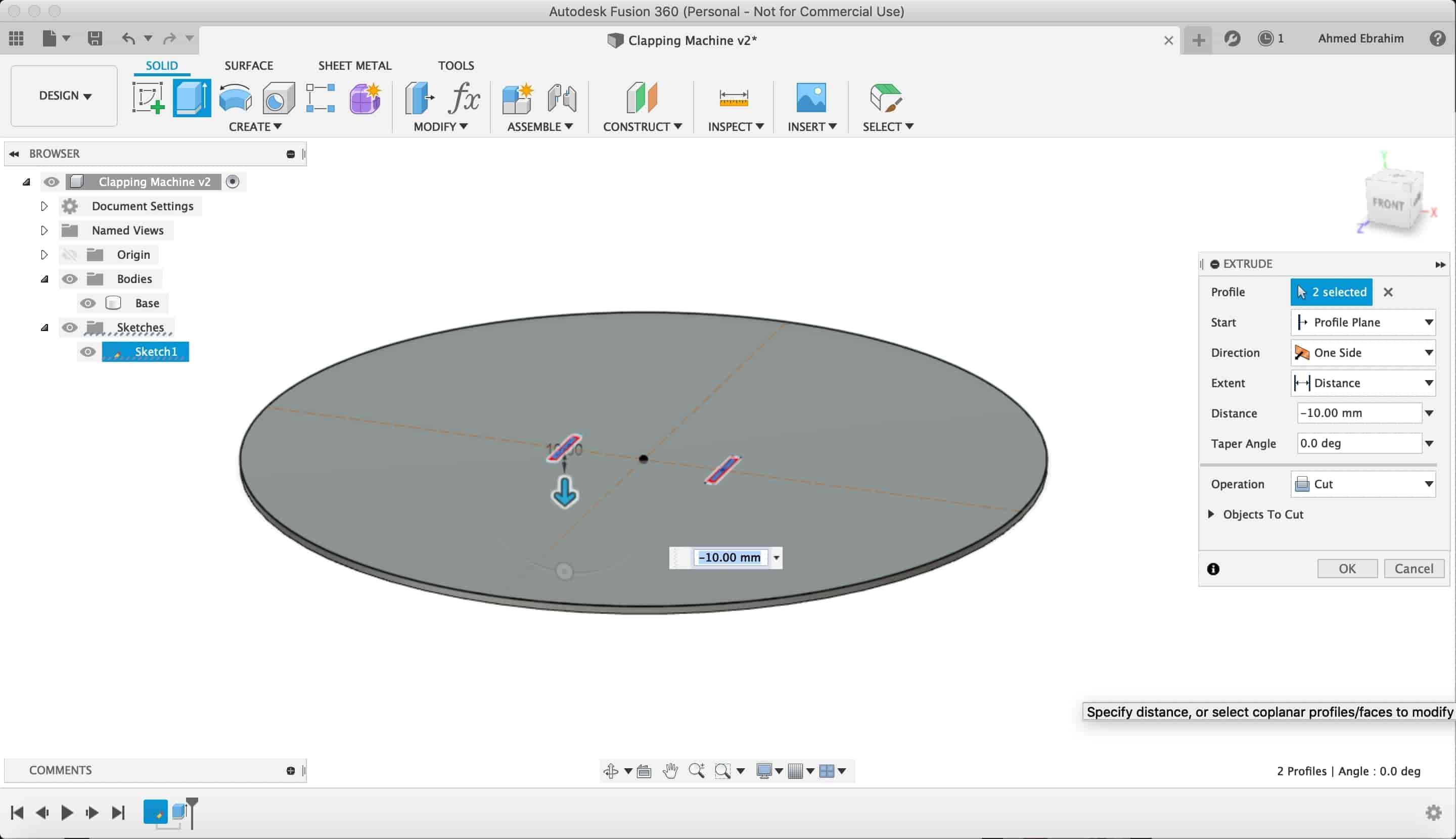
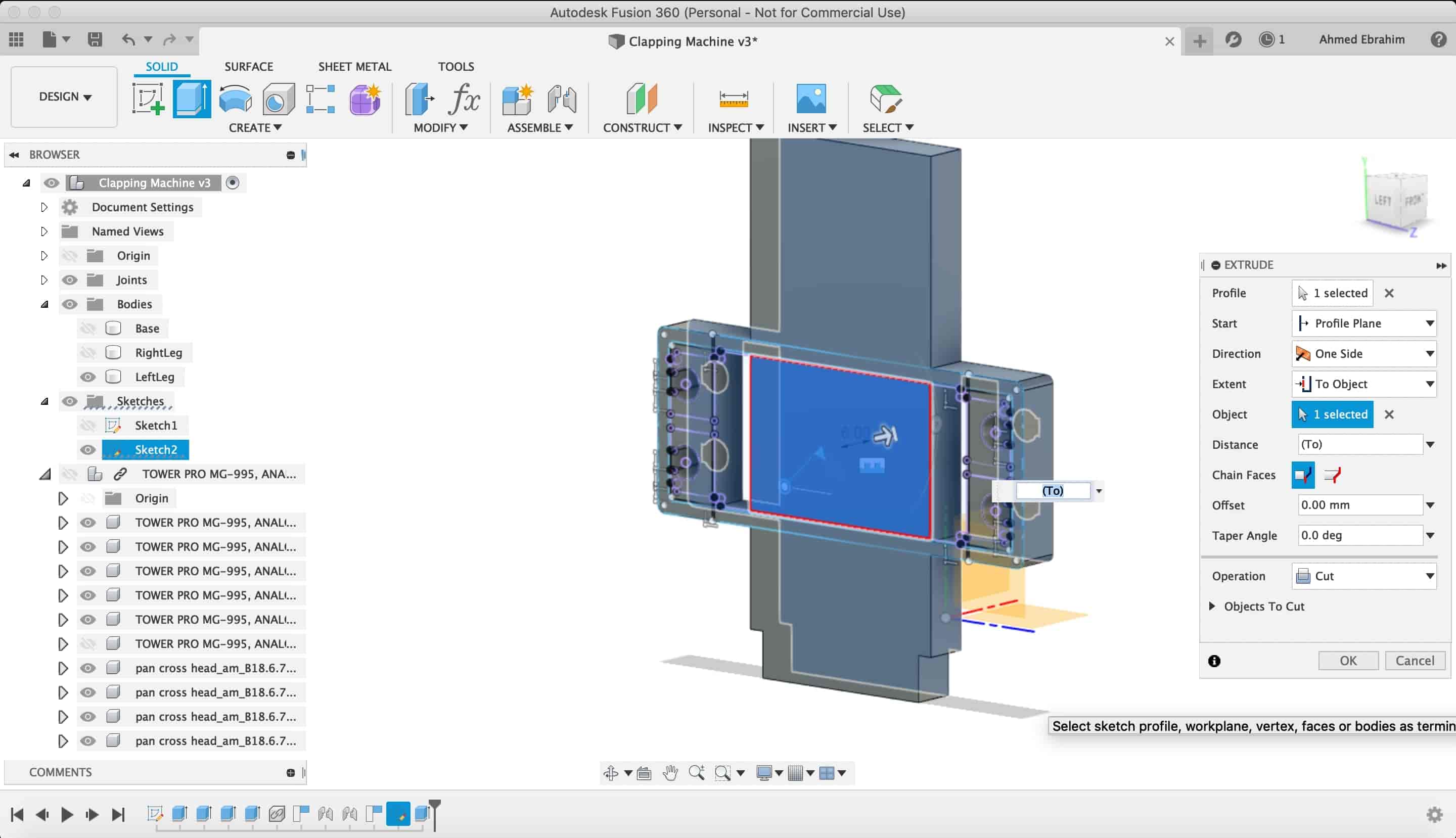
After that, I selected the two small rectangles(fittings) to make it a cut. to allow the front & back faces to get inserted inside it.
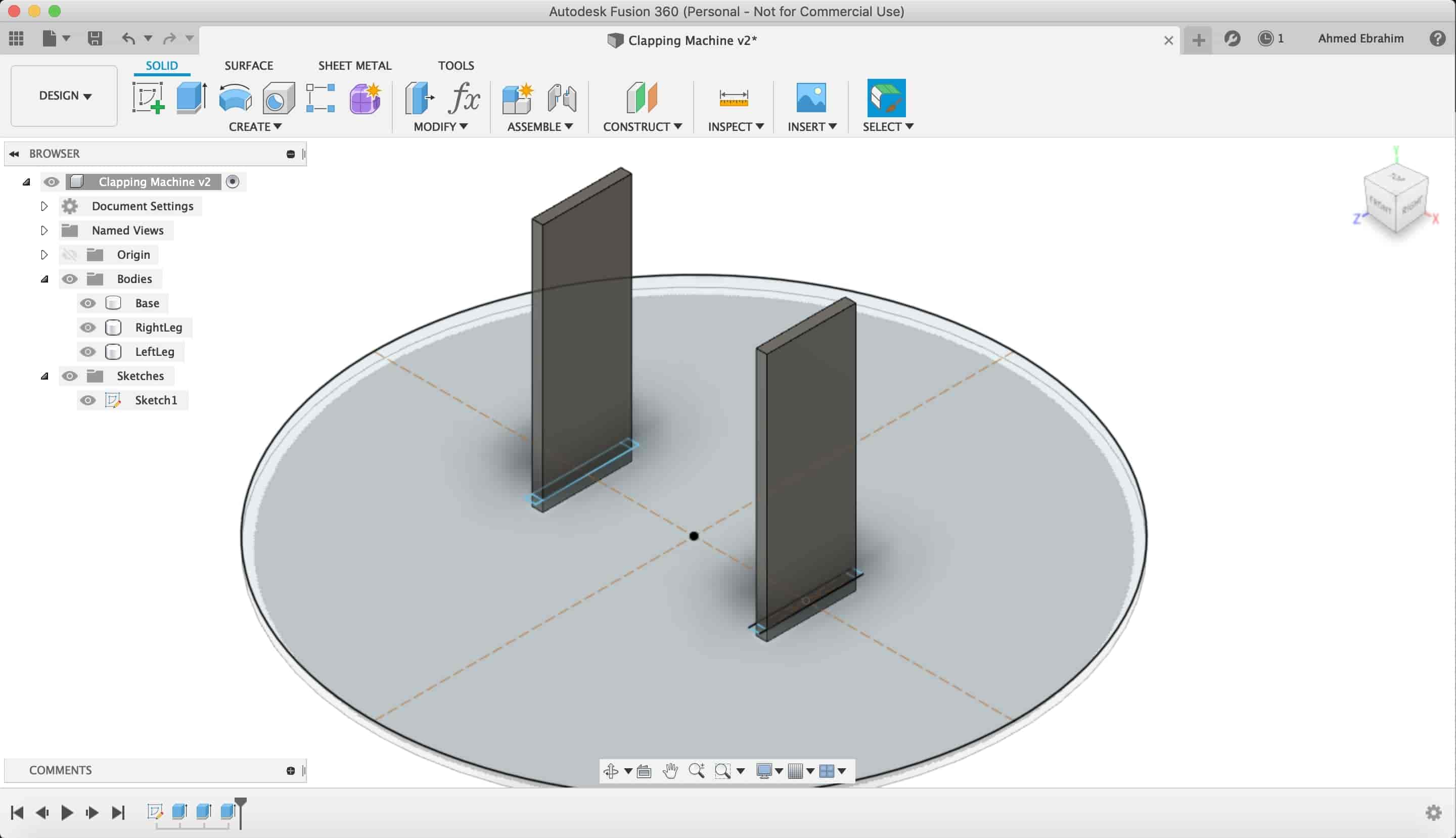
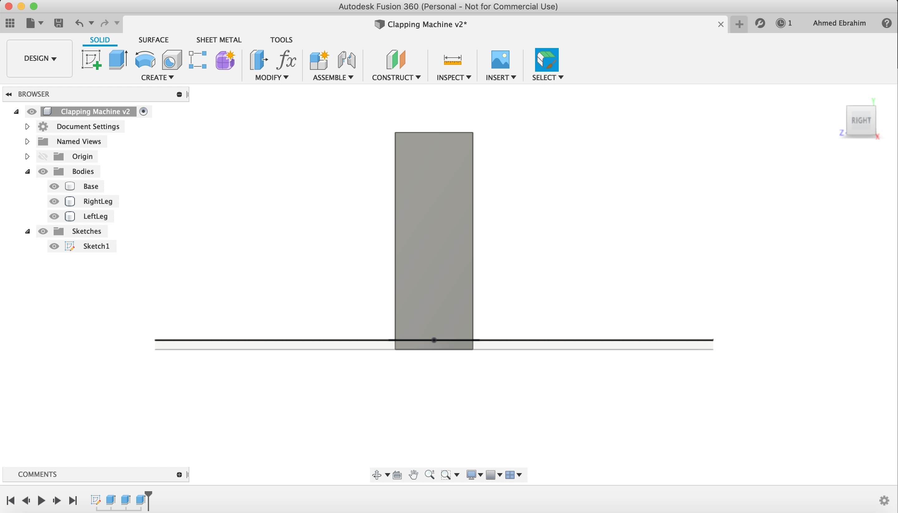
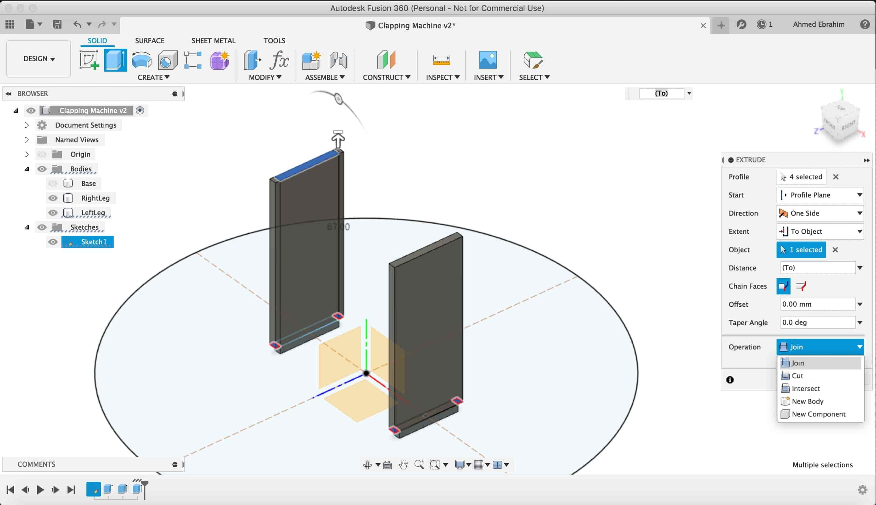
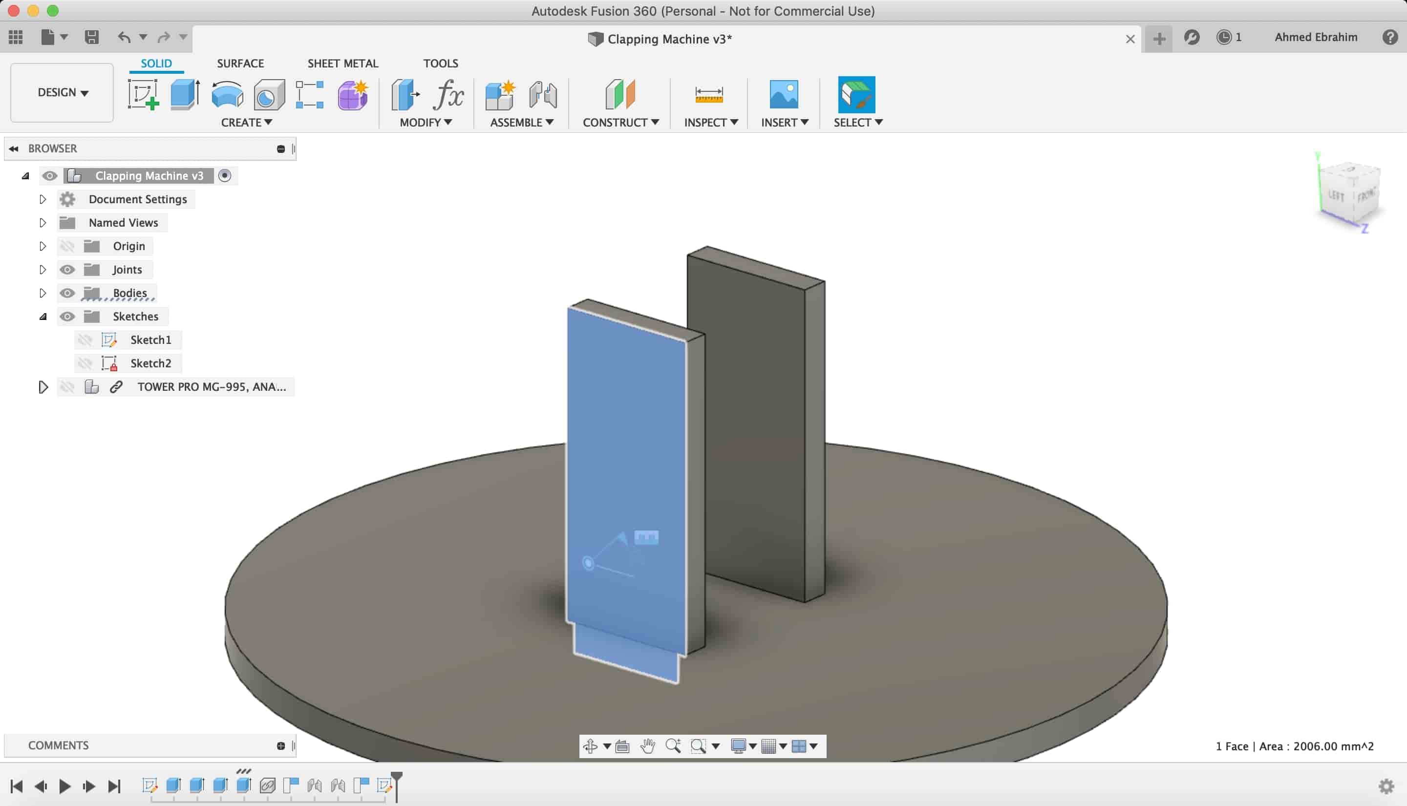
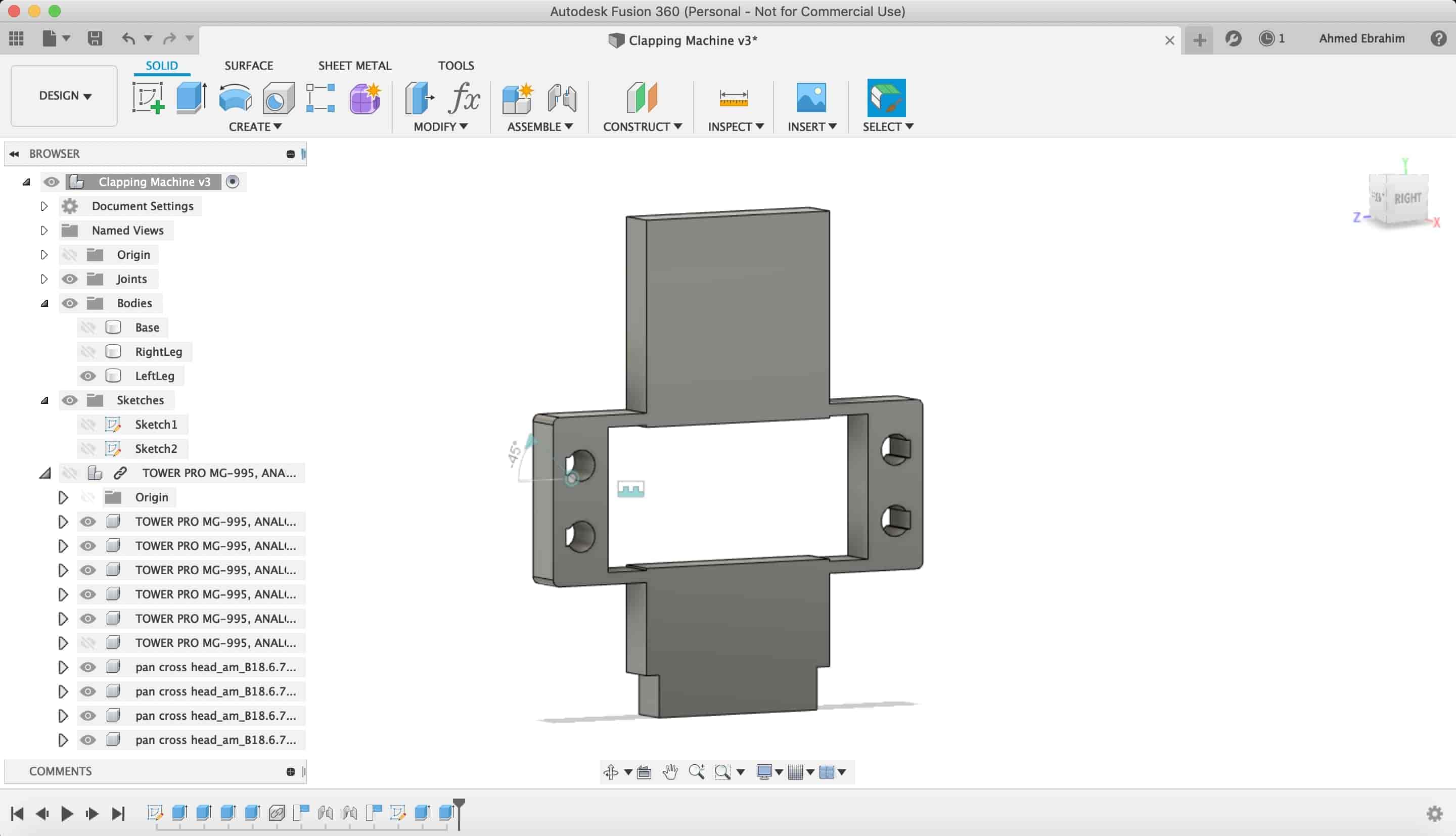
After that, I selected the two small rectangles again but this time to extrude it as a new component to make the front & back faces that will hide the internal mechanicm
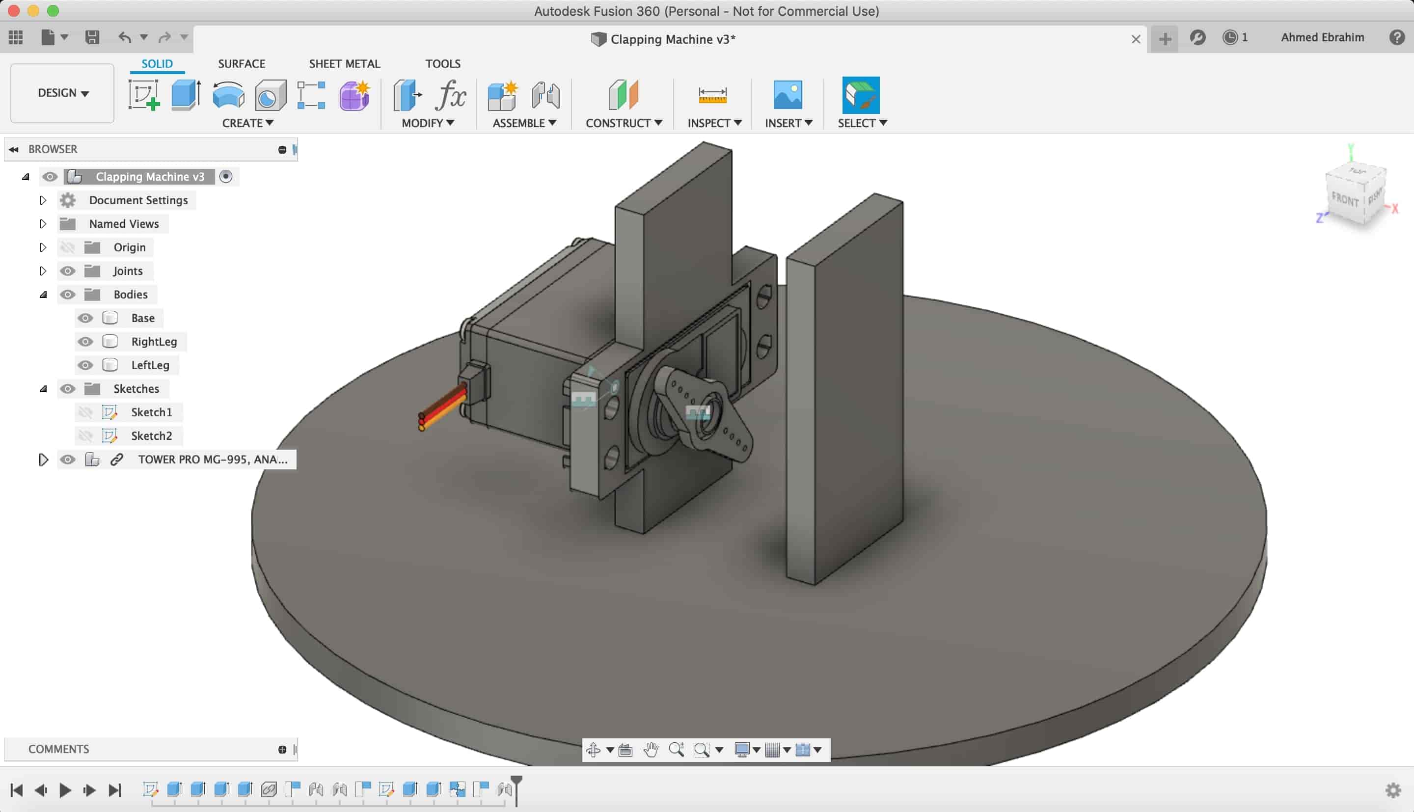
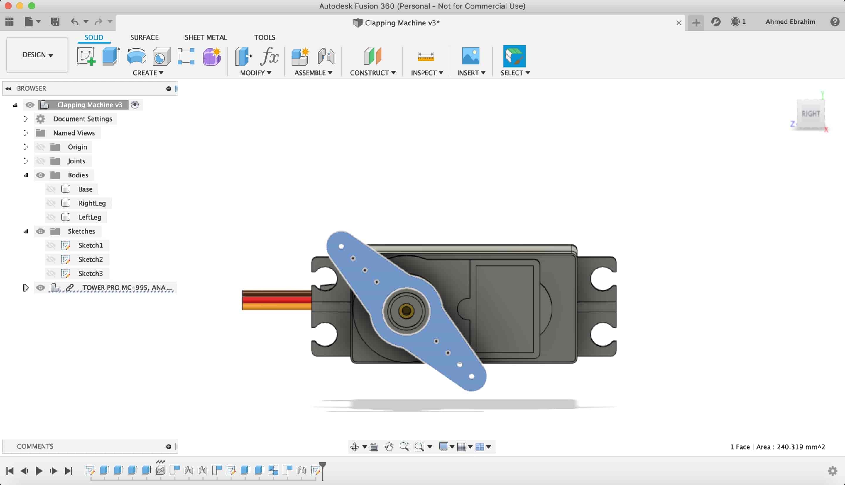
Then, I downloaded an MG955 servo motor as a STP file to insert it in my design. So, I can take the dimensions of it easily in my design.
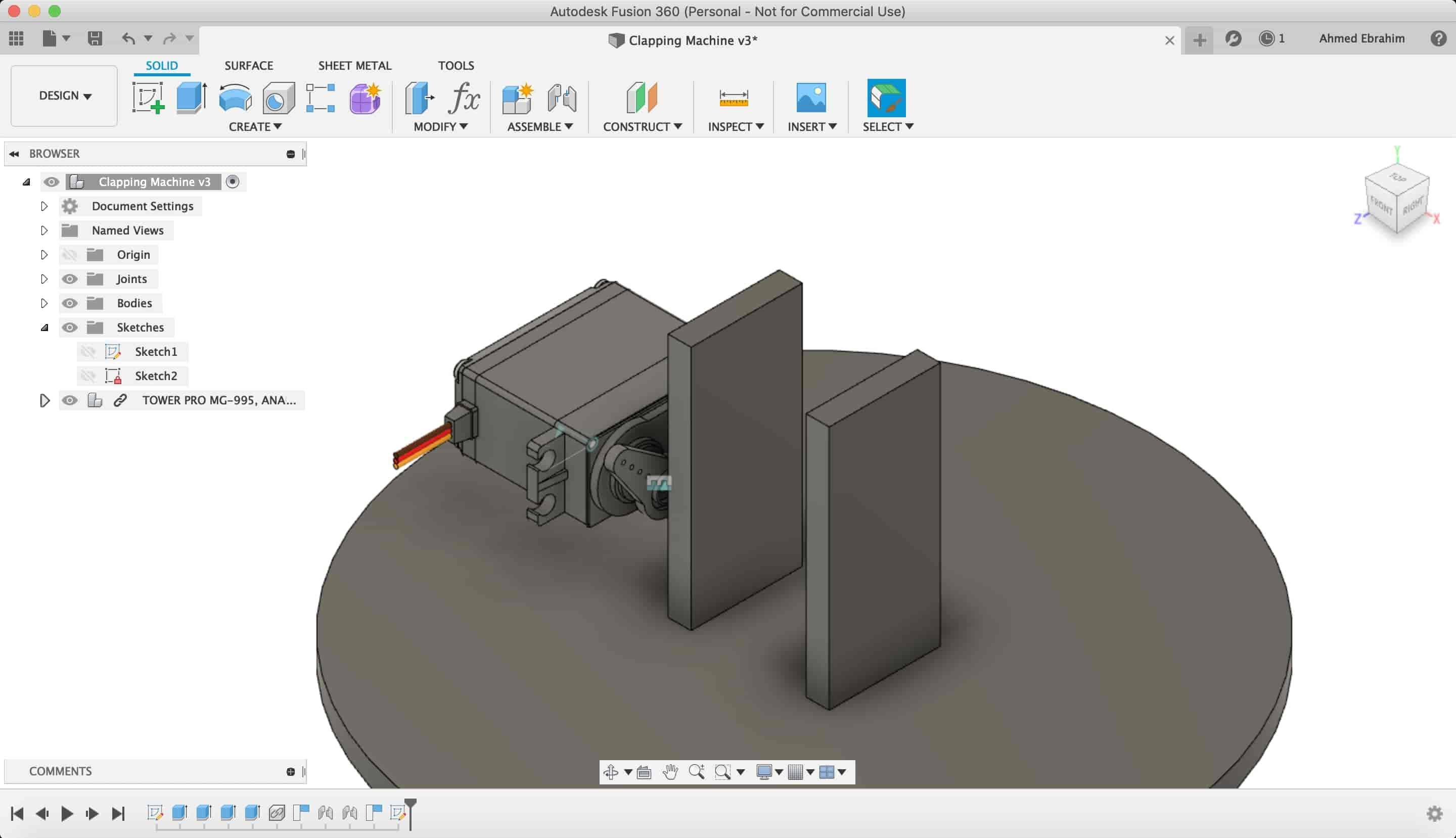
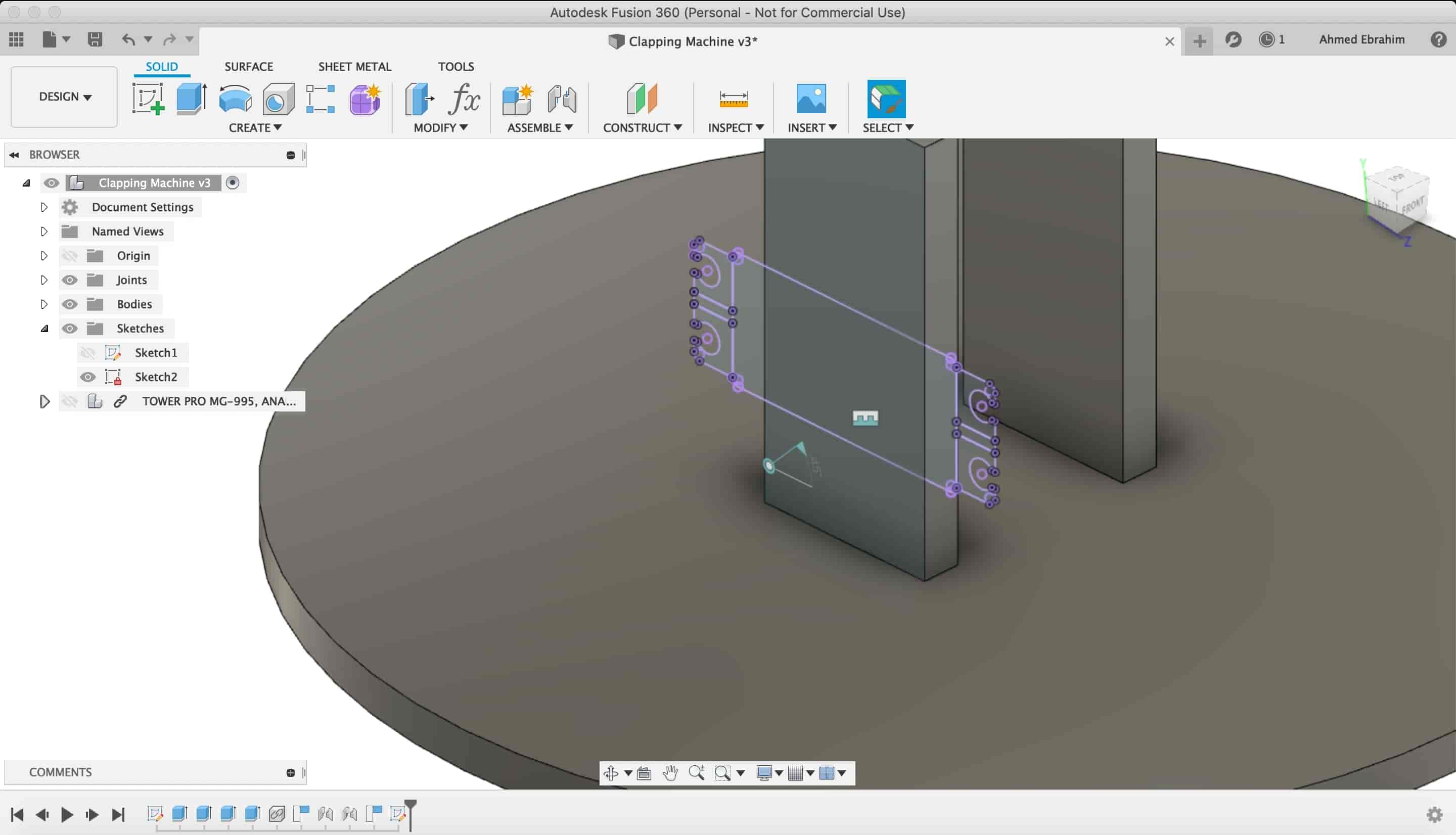
I made a sketch on that surface to make a place to install the servo motor in it.
I make a "project" to the servo motor body on my sketch surface with it's holes and curves.
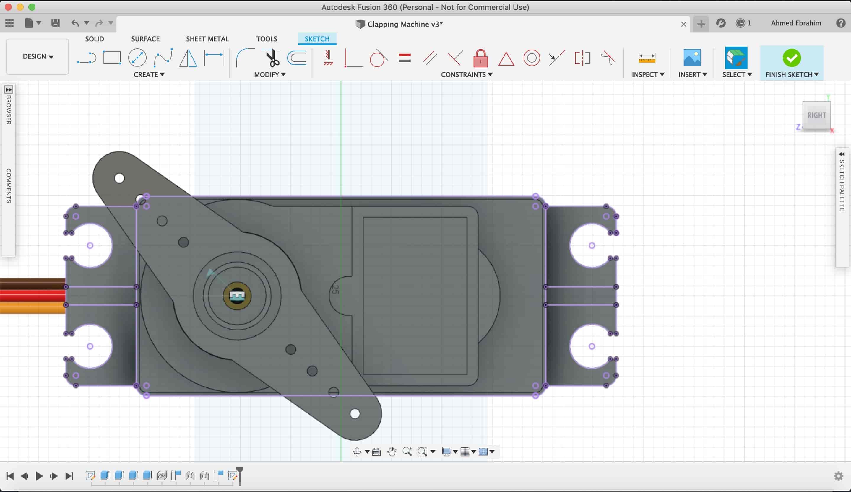
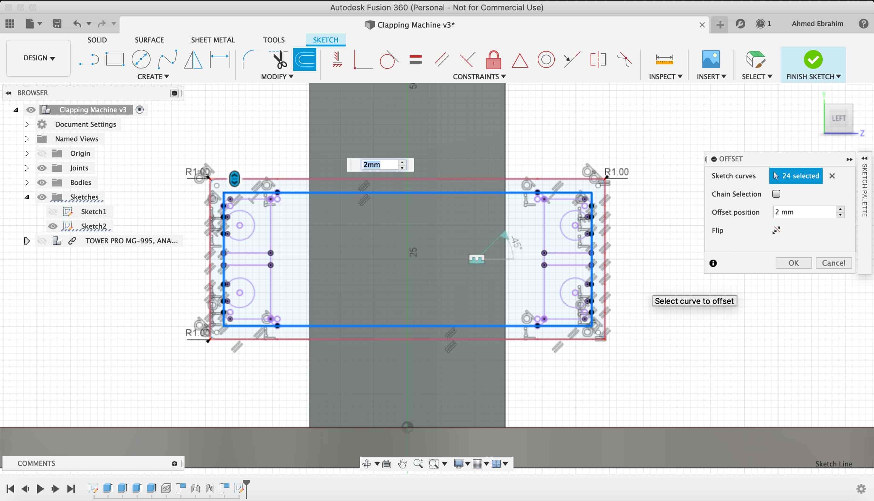
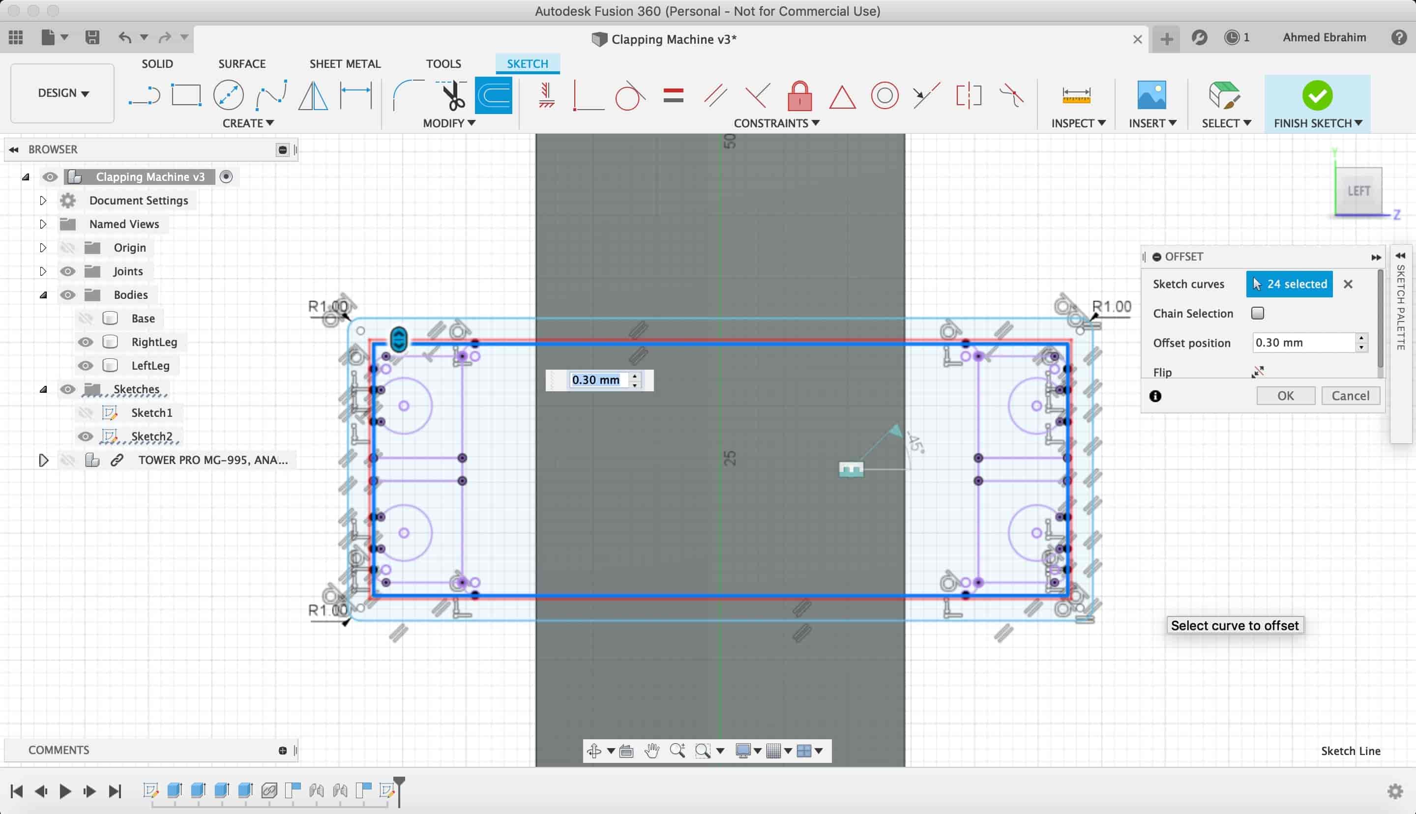
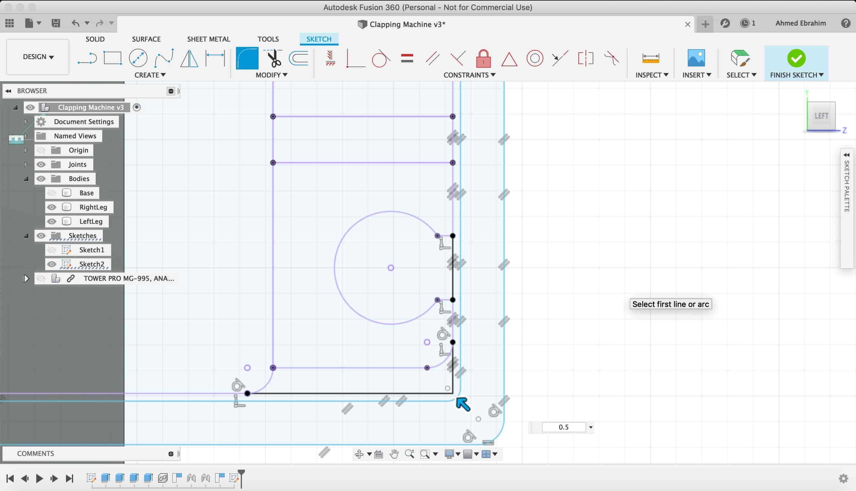
Making some offsets and fillets to make the servo motor installation process easier.
Then I extruded my servo motor sketch
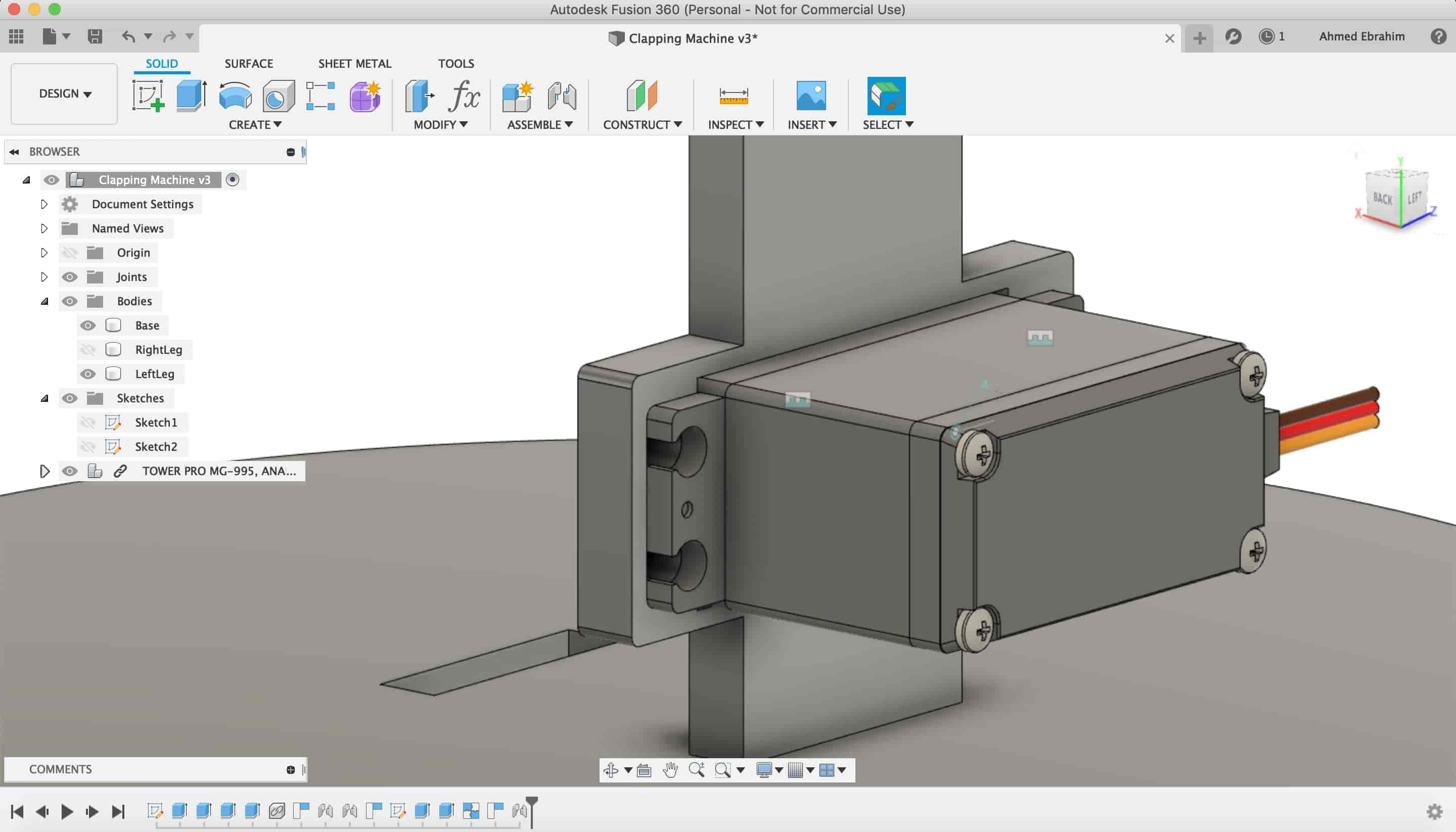
I used the "Joint" tool from the "Assembly" category to make a rigid joint between the back face of the robot and the servo motor. The rigit joint is like welding to pieces together.
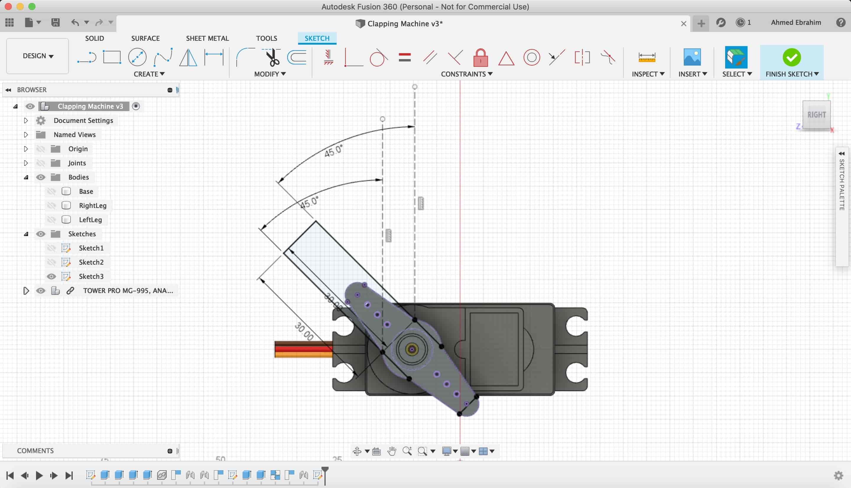
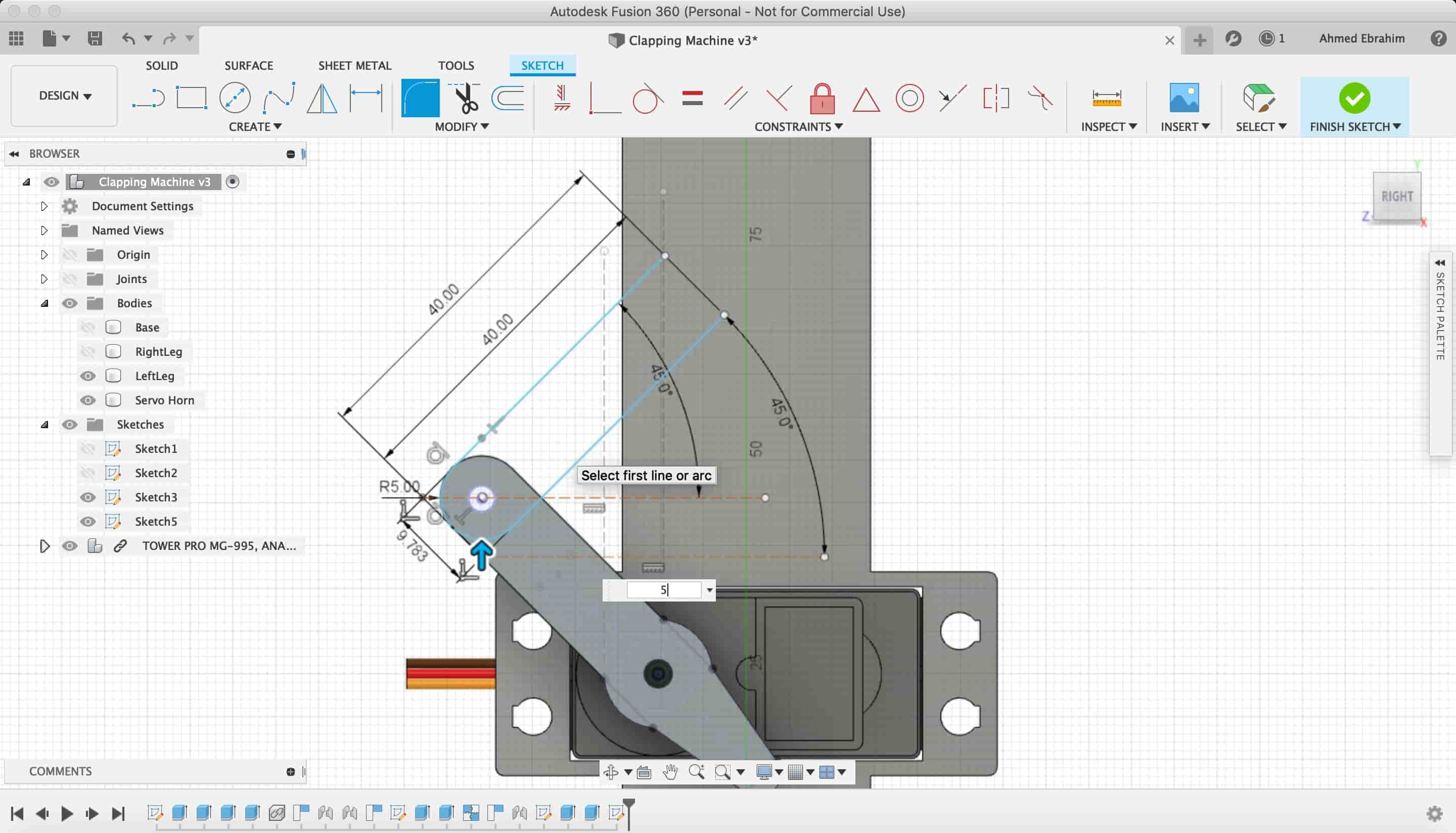
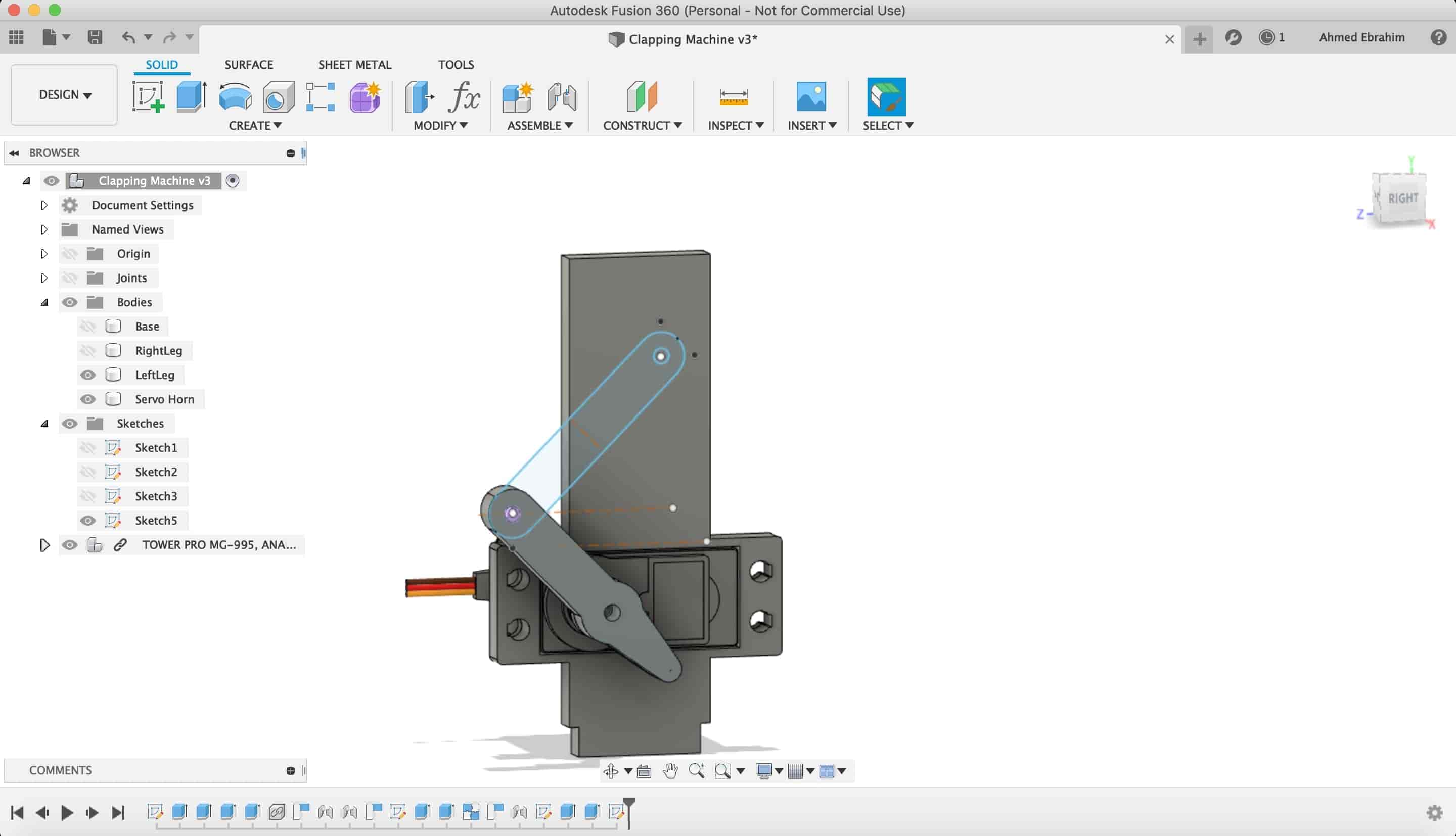
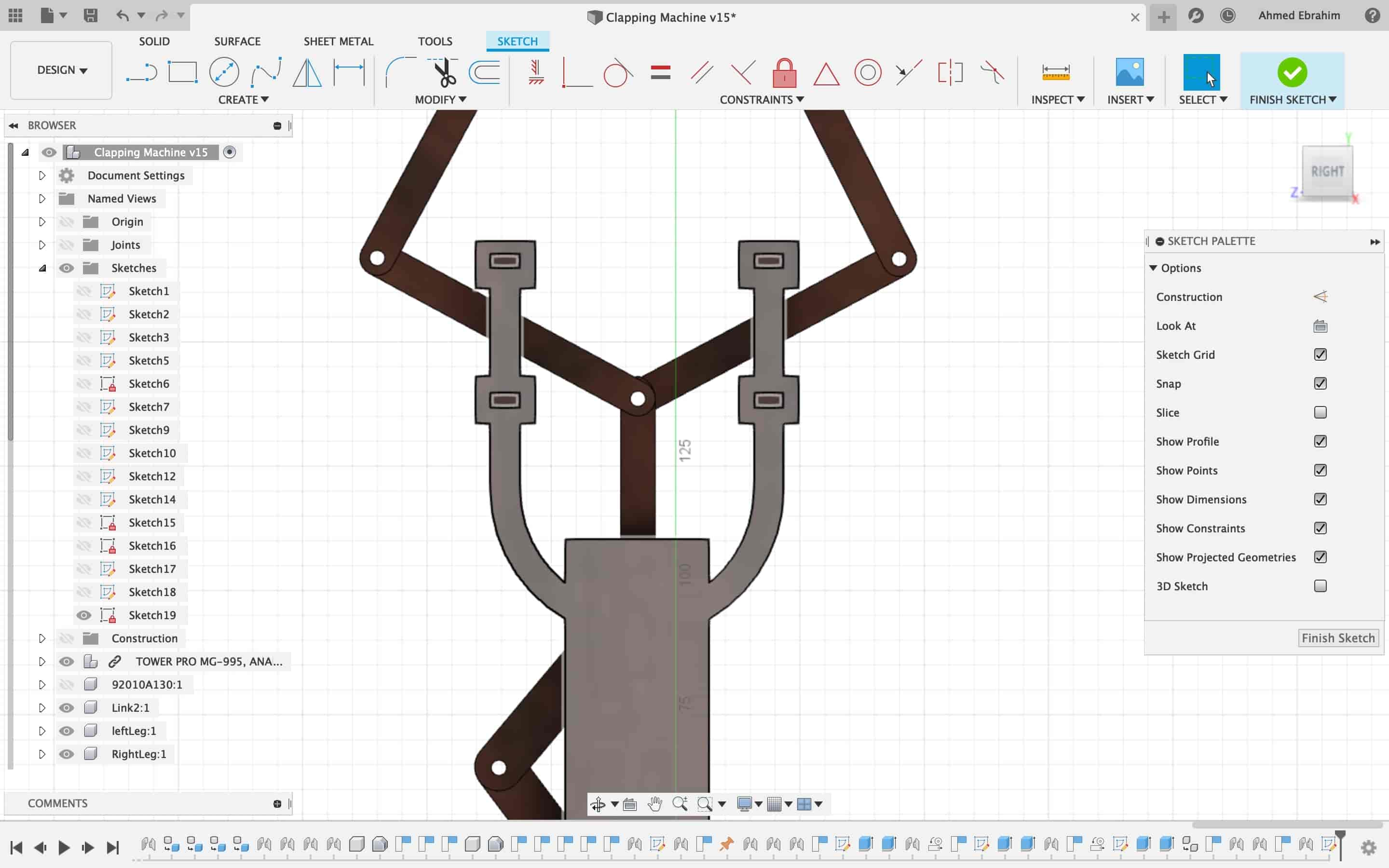
Now, I want to make the first link in my robot, thhis link:
I made a new sketch on this plane.
I draw a rectangle on the servo horn with a 3mm hole in the midle in order to fix that part with the servo motor shaft as one part.
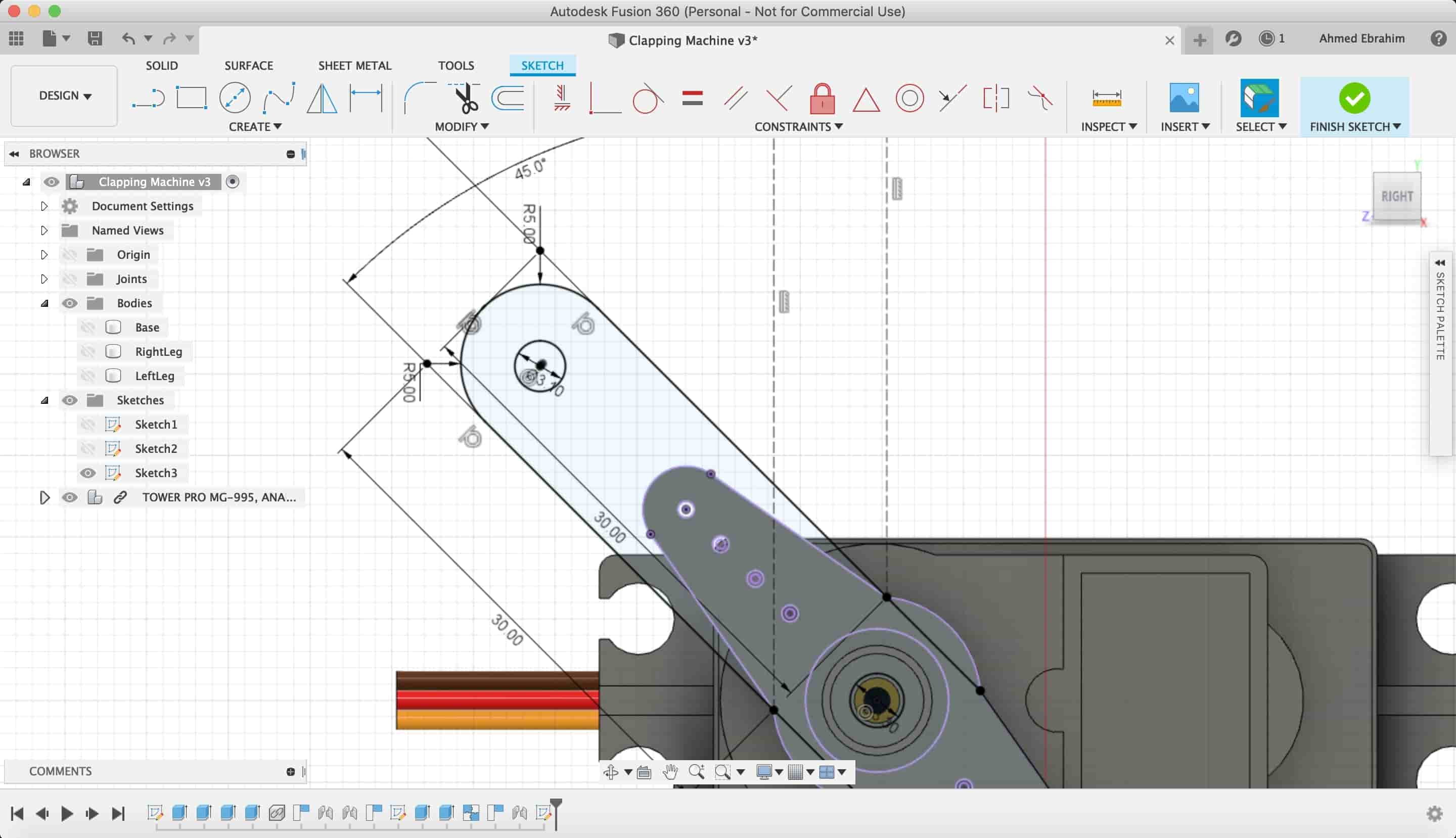
Then extruded that sketch as a new part.
After we finished the first link, We need to make the second one.
I created a new sketch on the first link plane we made to make the second one.
Then we extruded it.
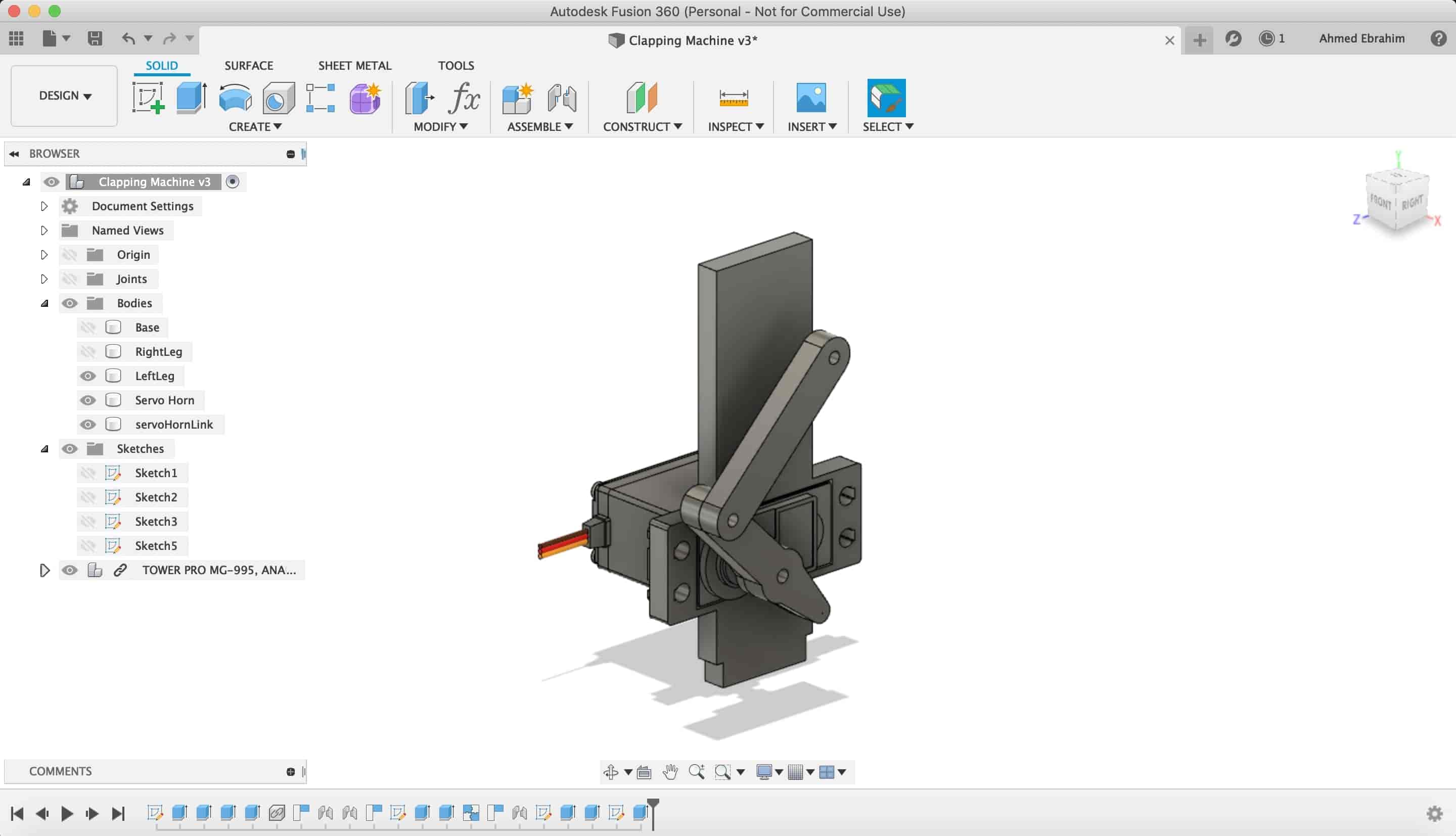
After we finished the seconds link, we wanna make the third link.

We did the same steps with the same concept that we made with the last two links.
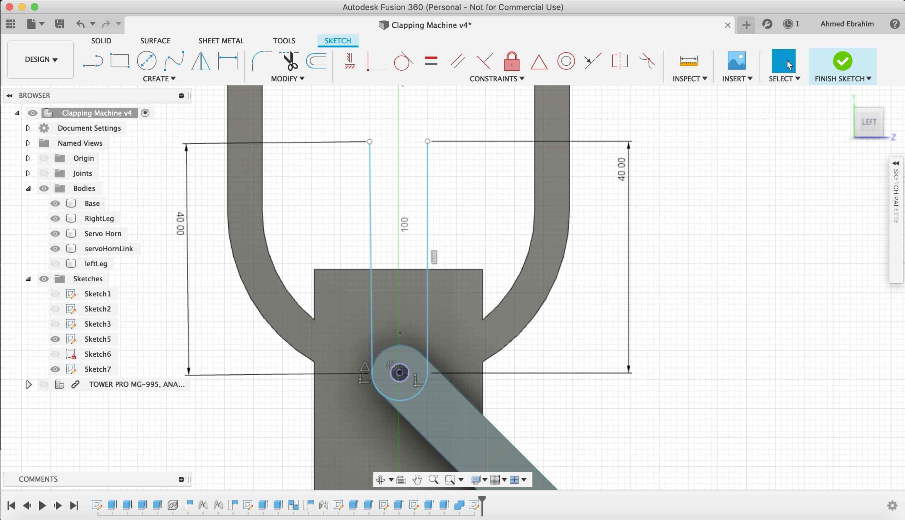
Now, we wanna make that "U" shape.
We created a new sketch on the back face.
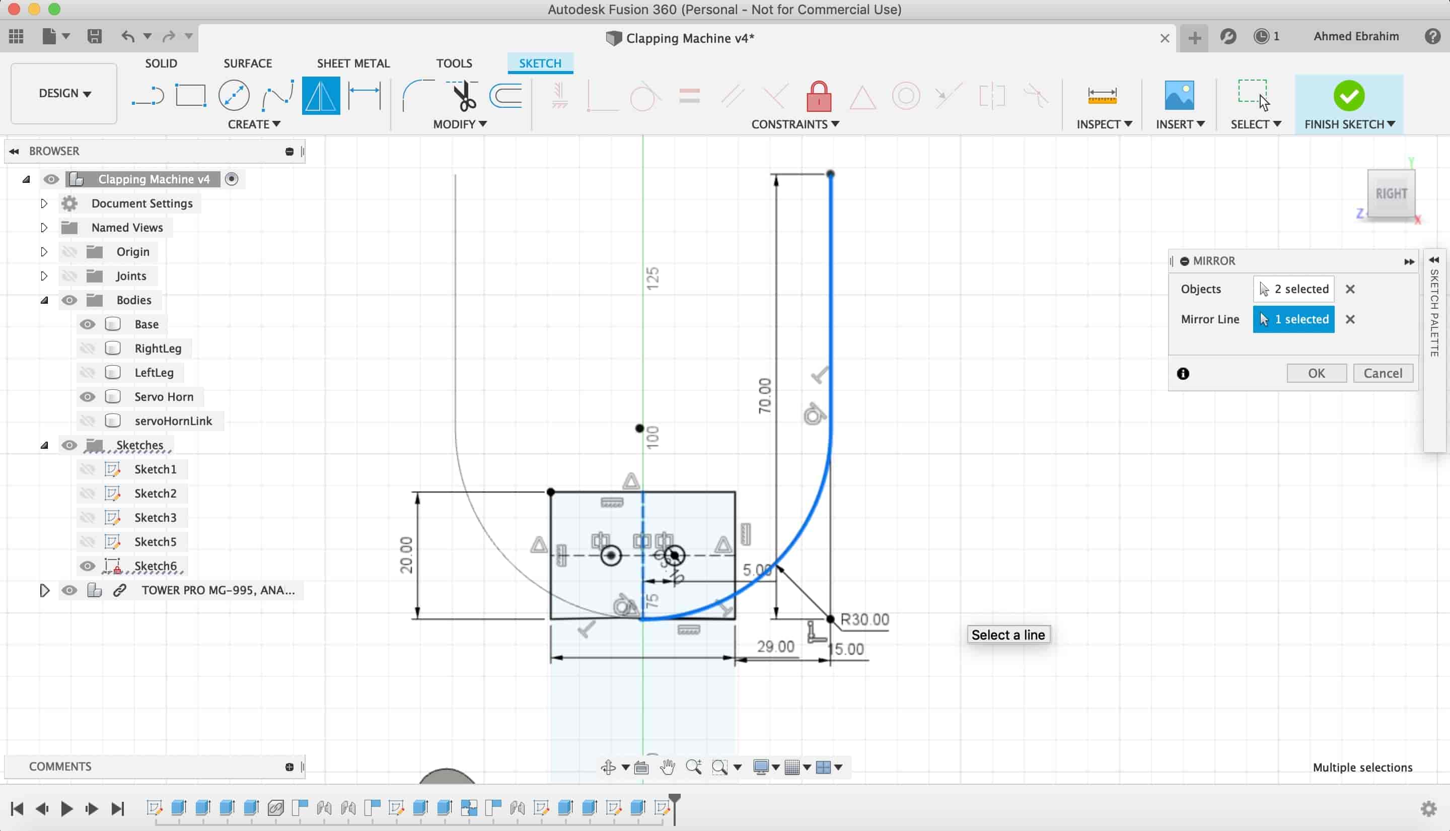
Making an "offset" to make it a closed shape in order to be able to make an "extrude" to it .
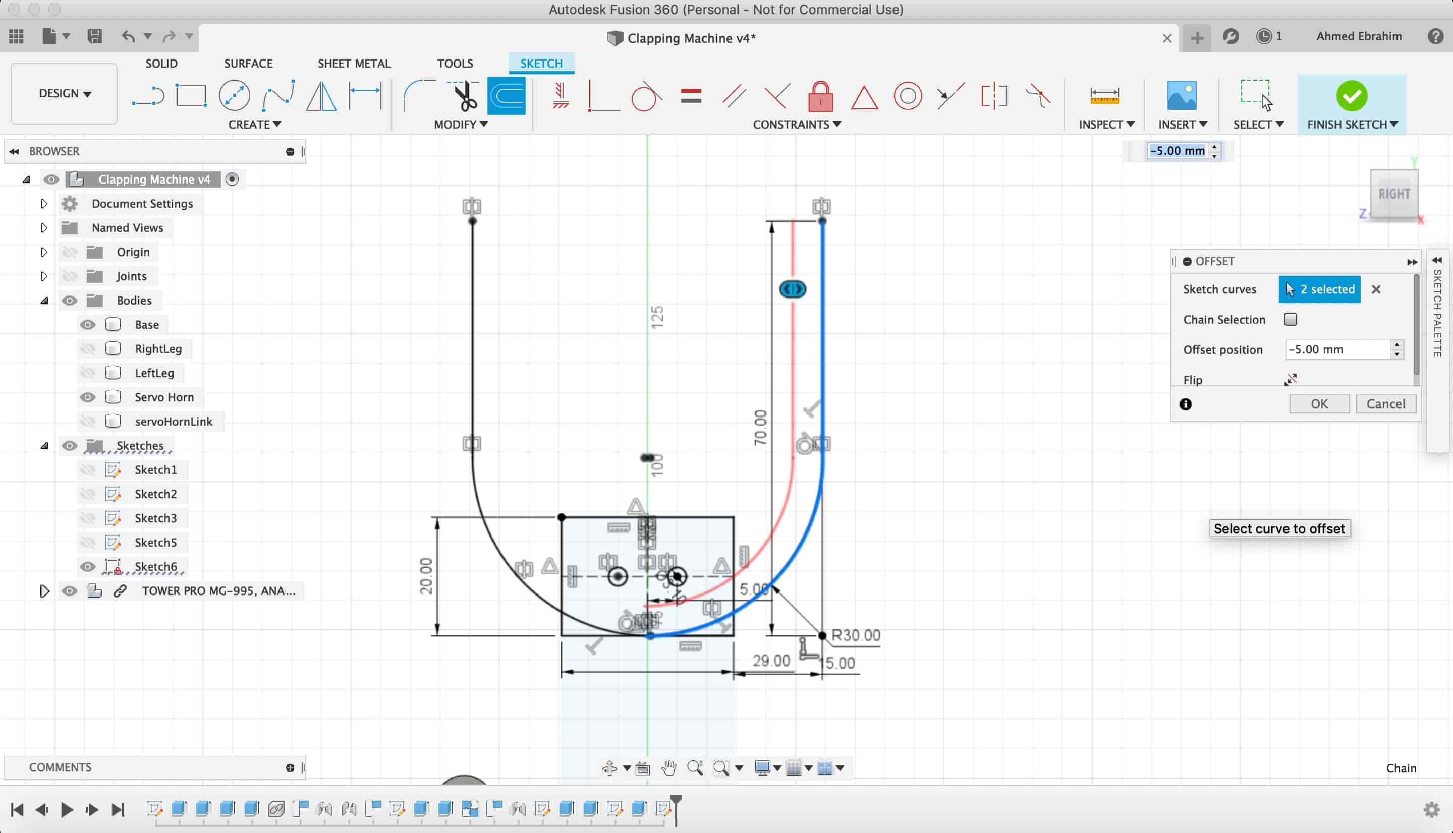
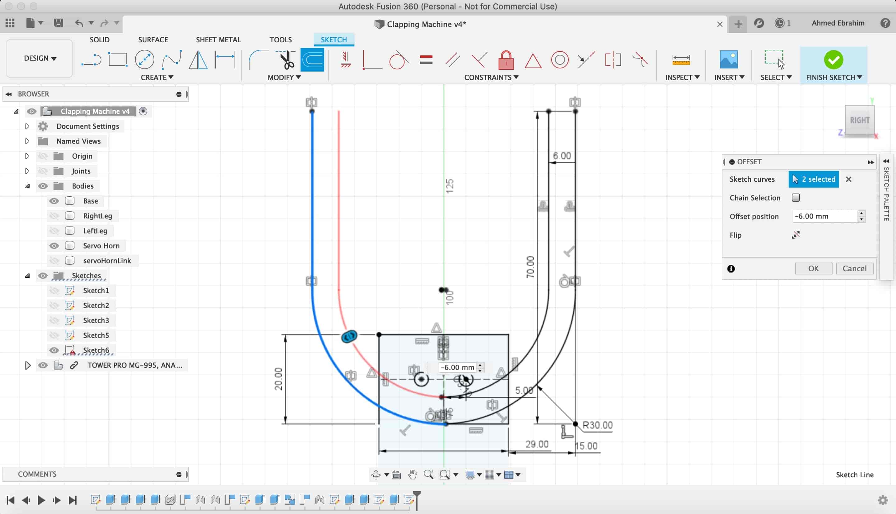
Then, we extruded that "U"shape
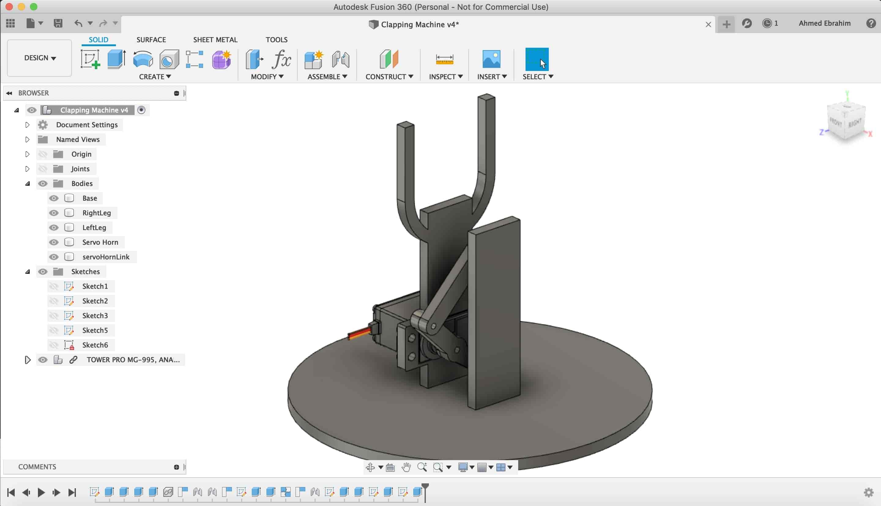
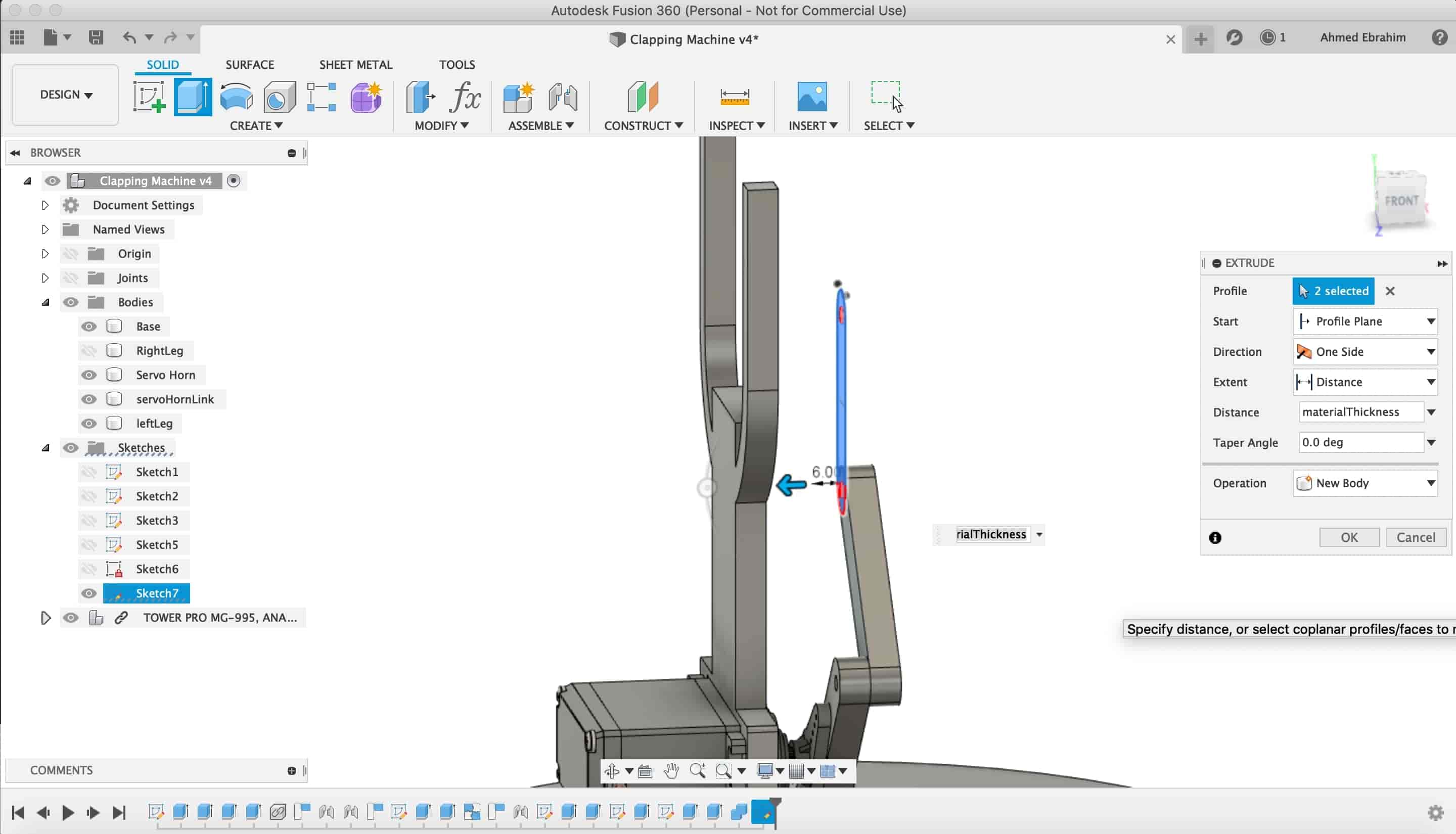
We created the fourth link like the previous three links. We sketched it then extruded it.
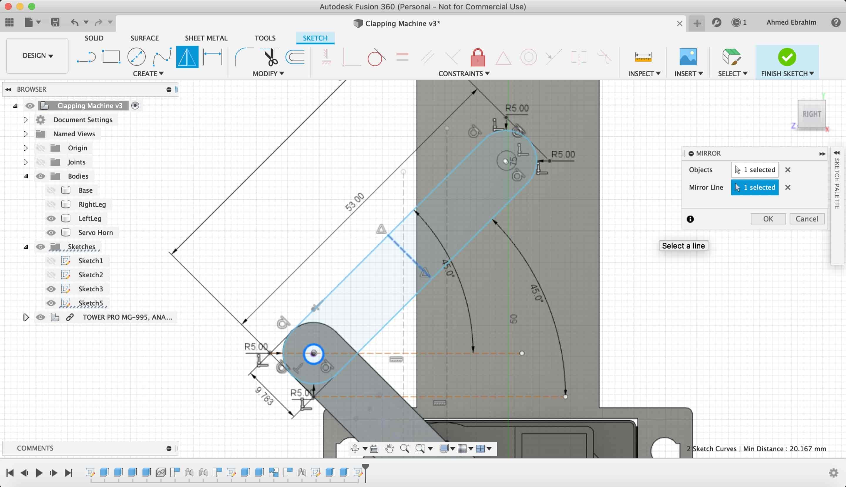
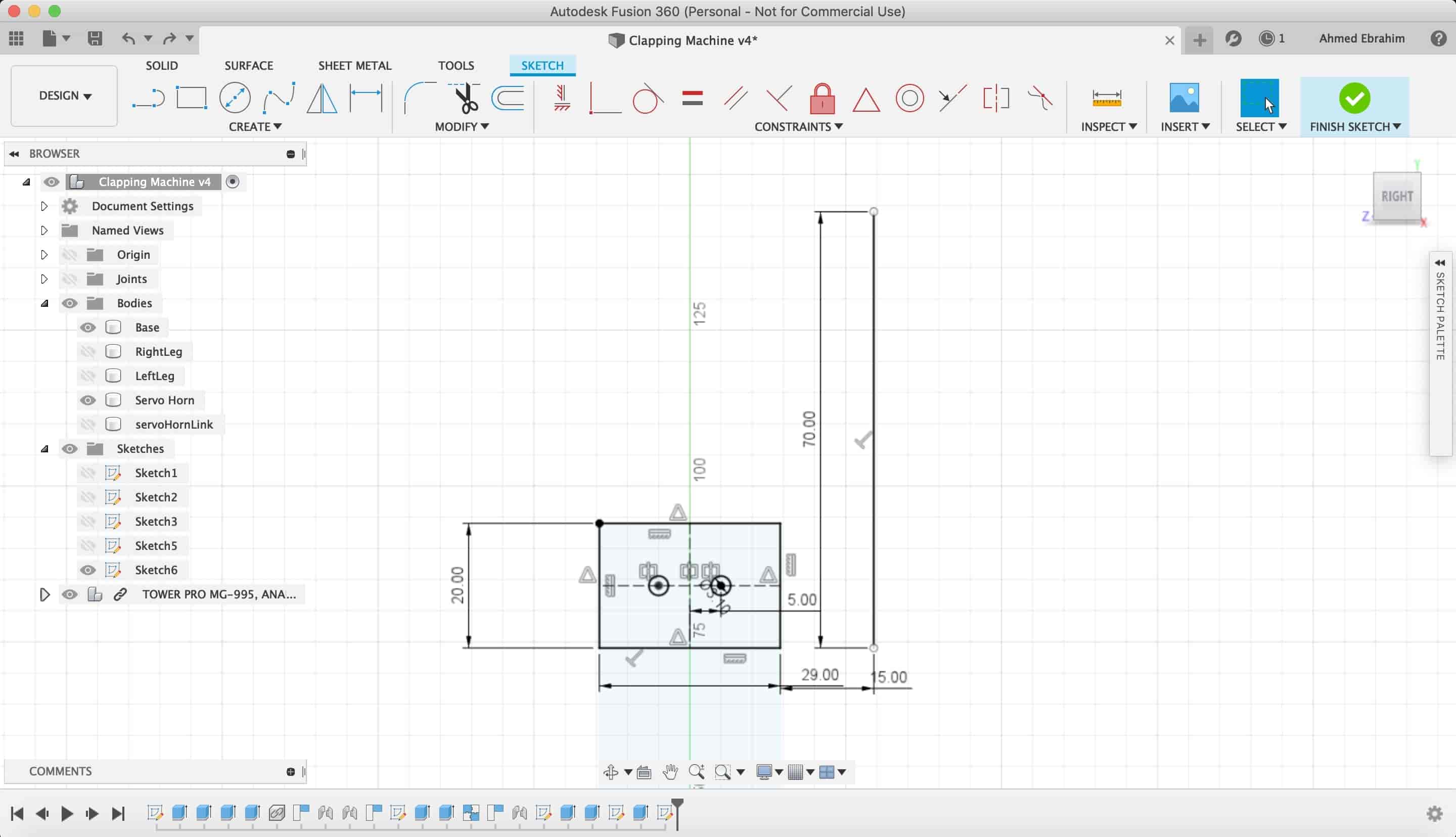
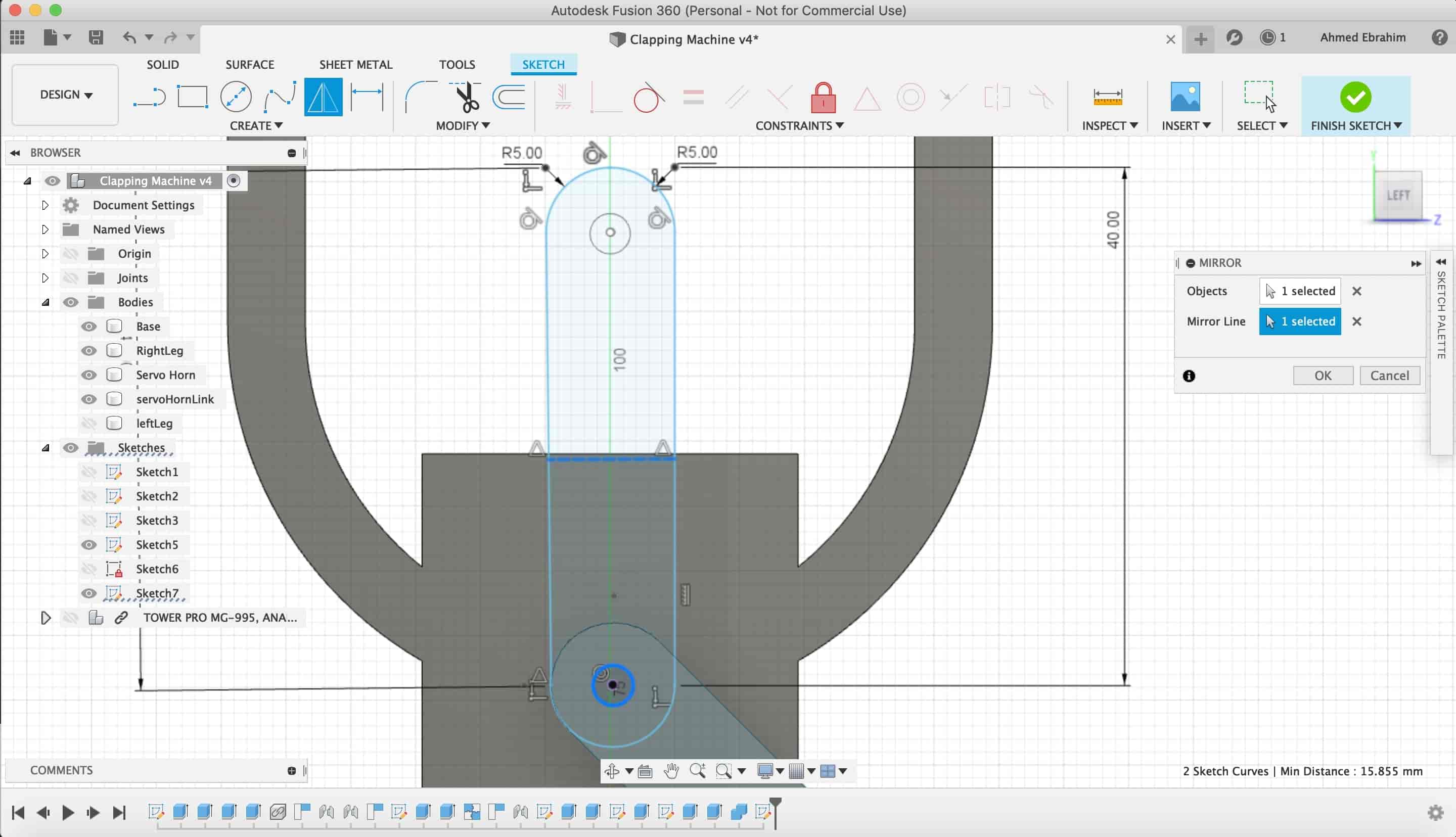
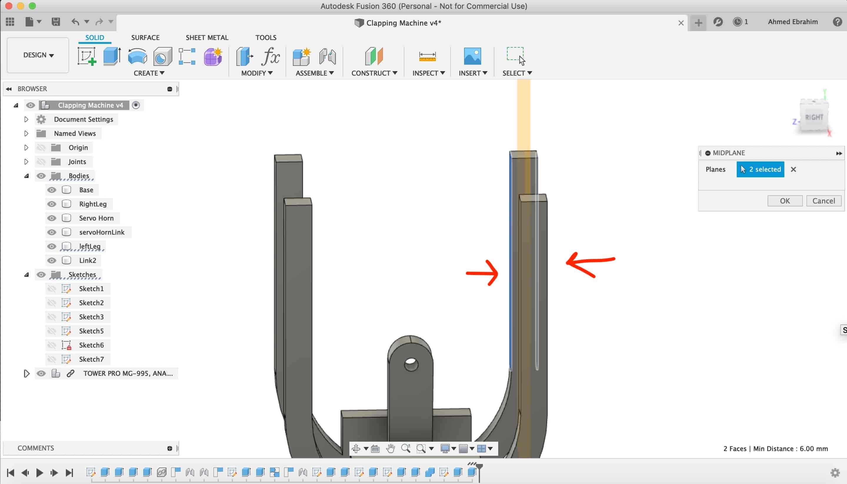
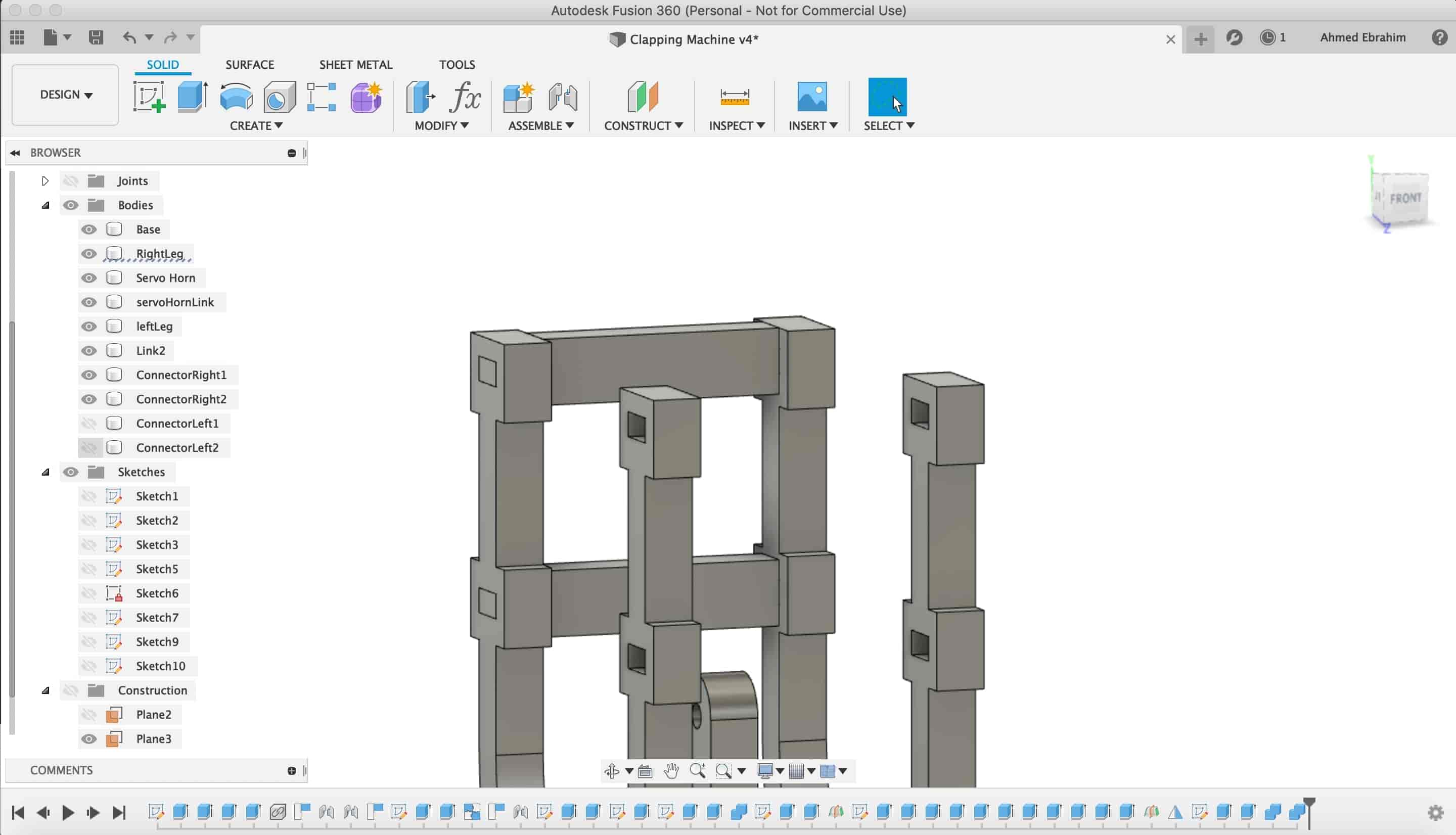
Now, we wanna fix the two faces (back and front) together and also the put a limit to the hands movement. We created a "Midplane" between these two faces.
I sketched that two robot faces connectors.
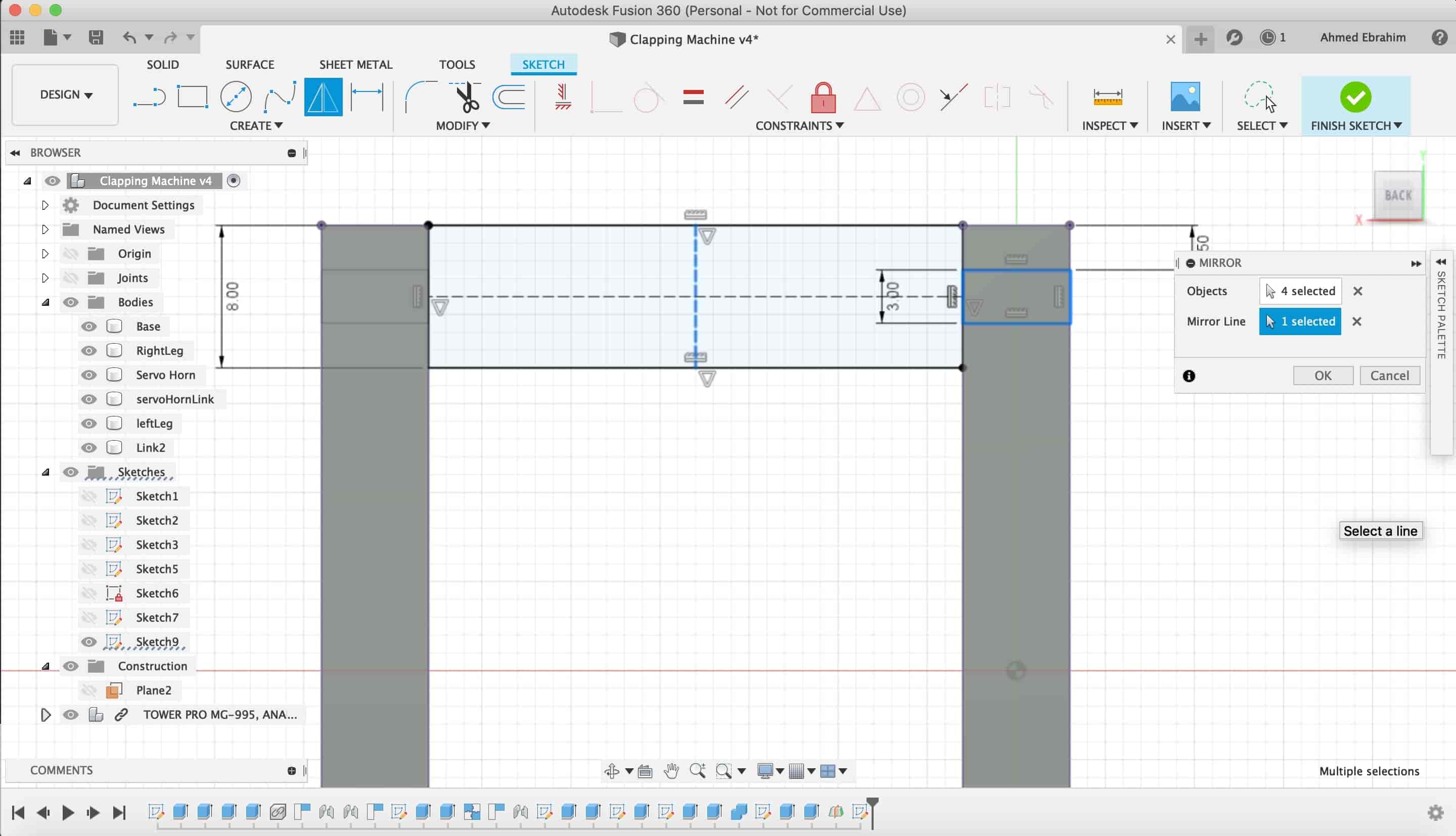
After extruding itas a new body, I made a "project" of that body to make a place for it to get fixed on.
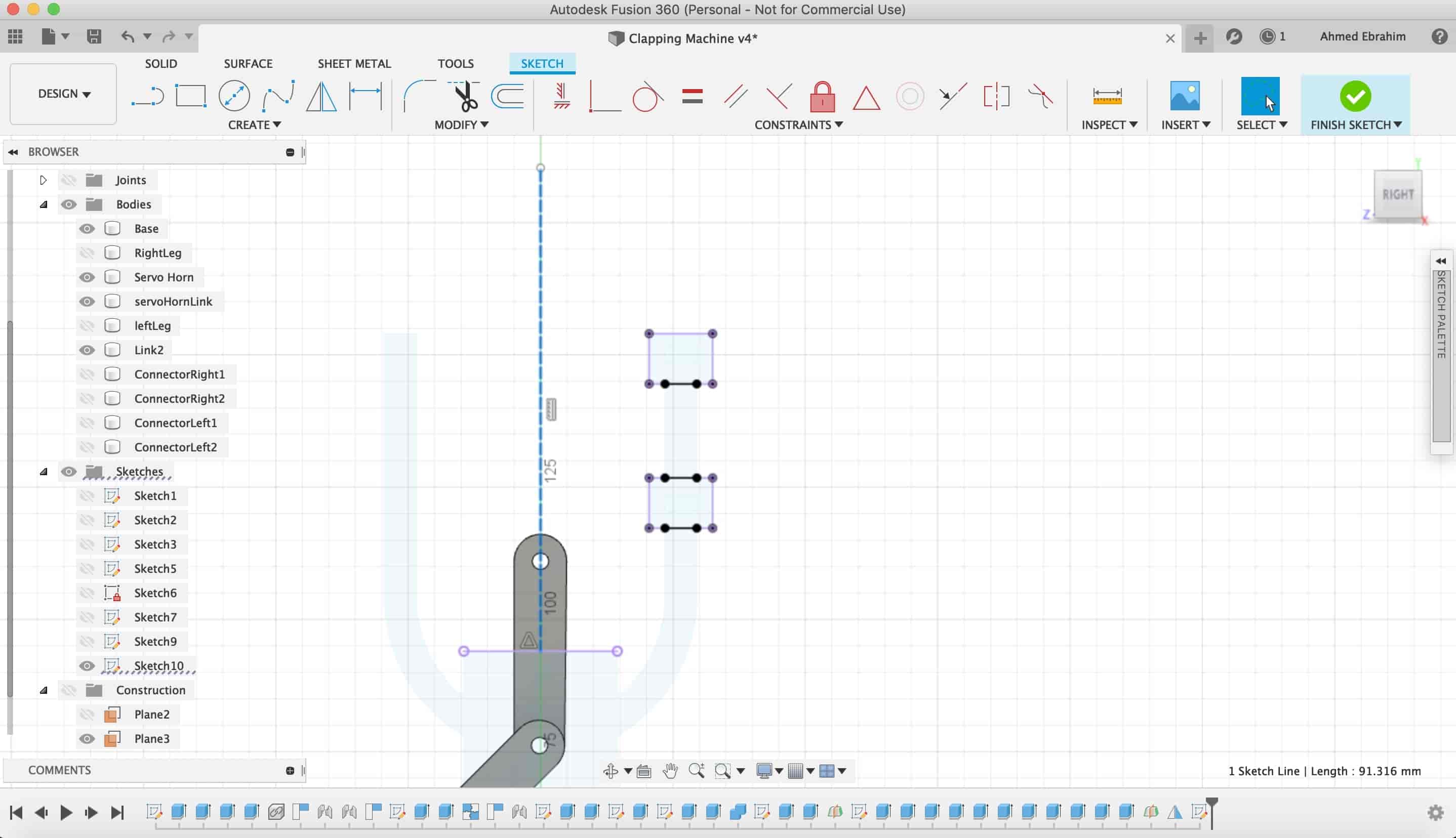
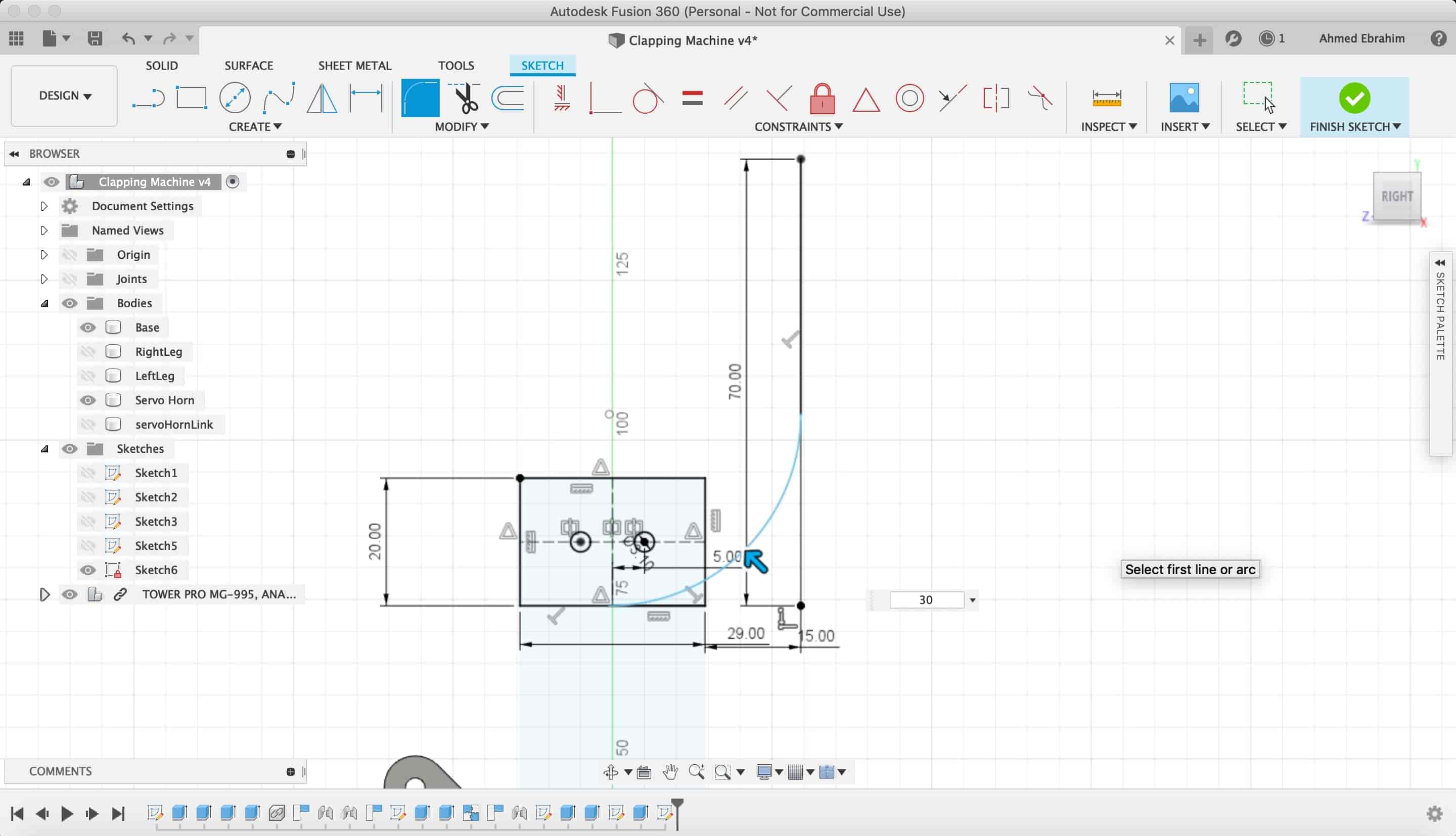
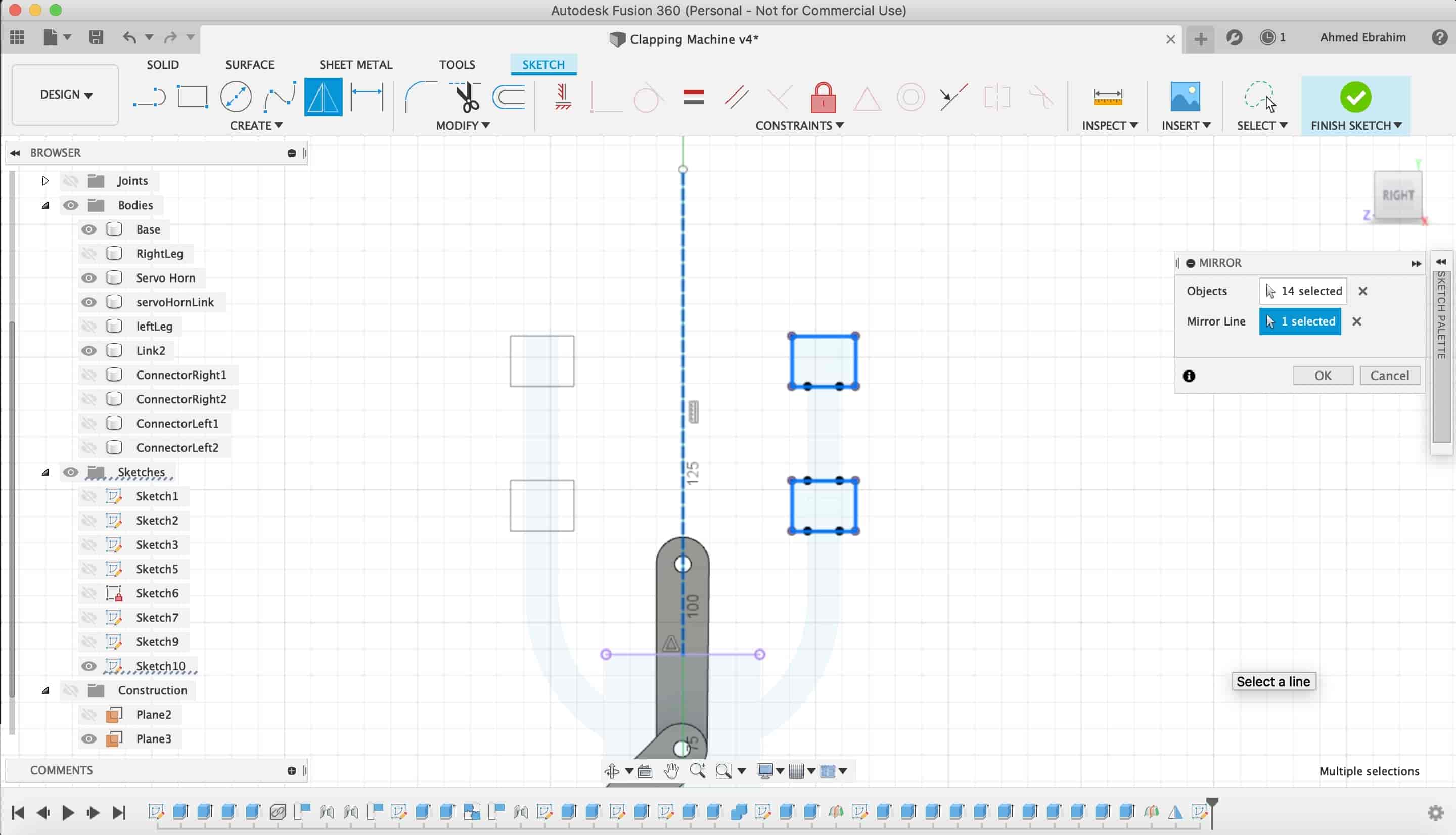
I made a midline as a construction line, then I mirrored them.
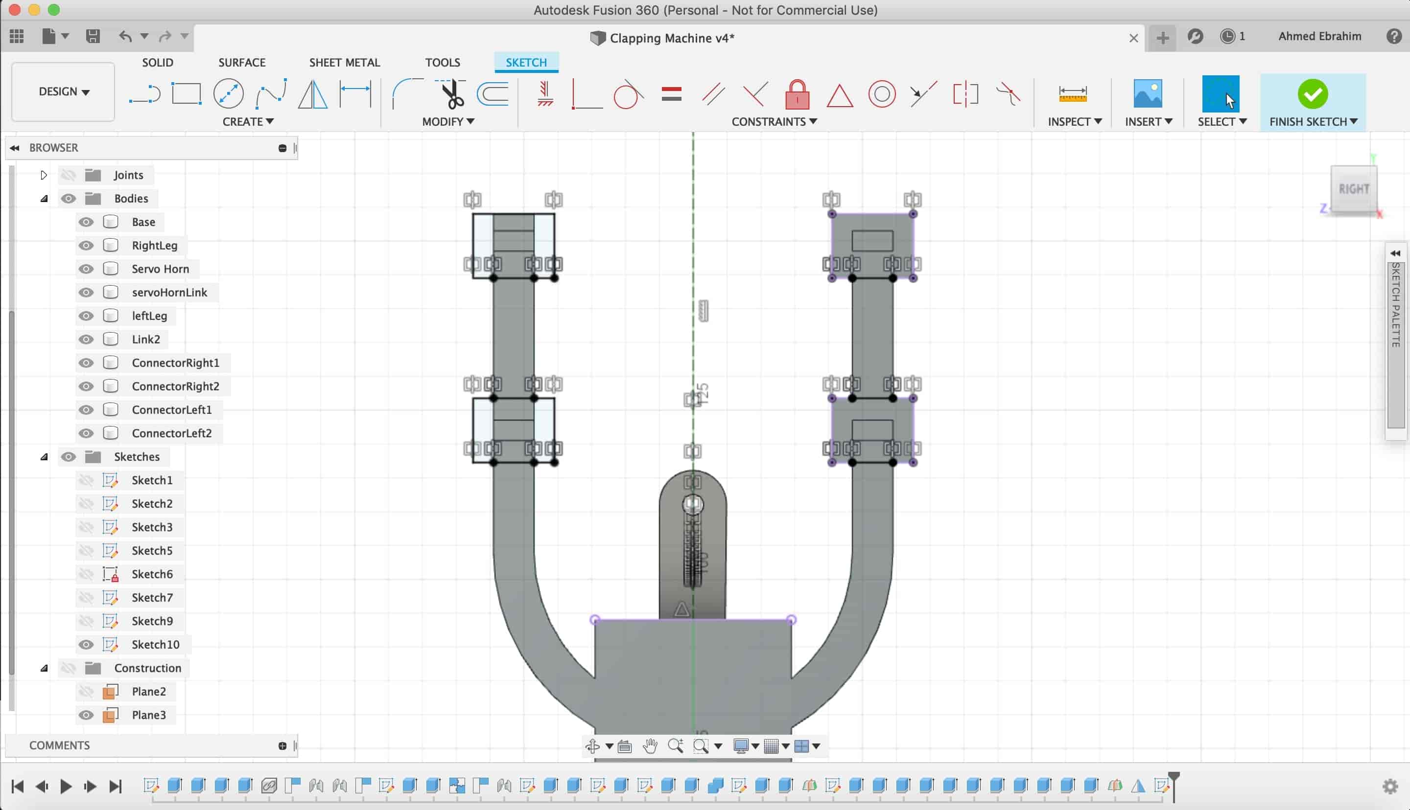
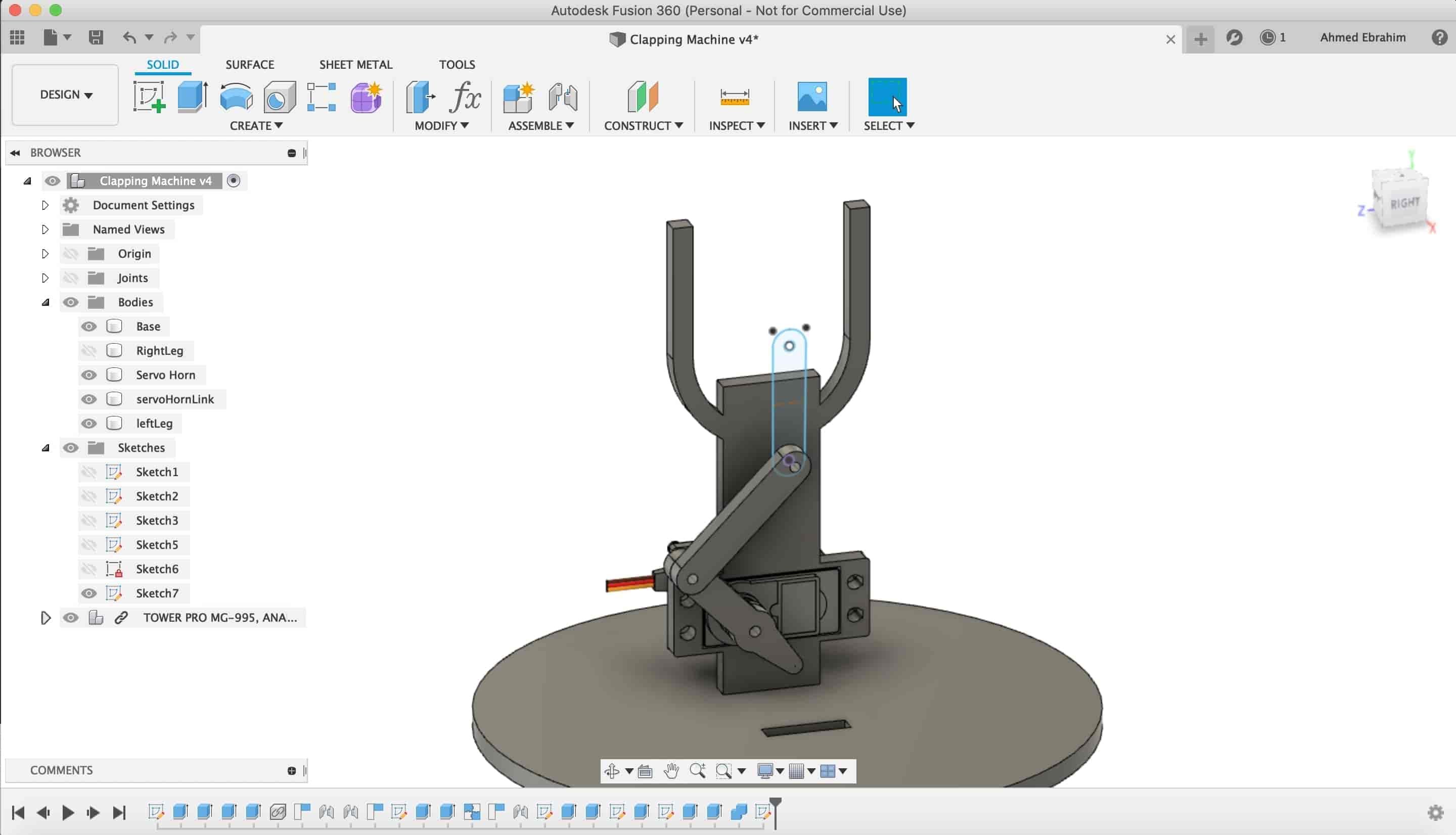
After extruding it.
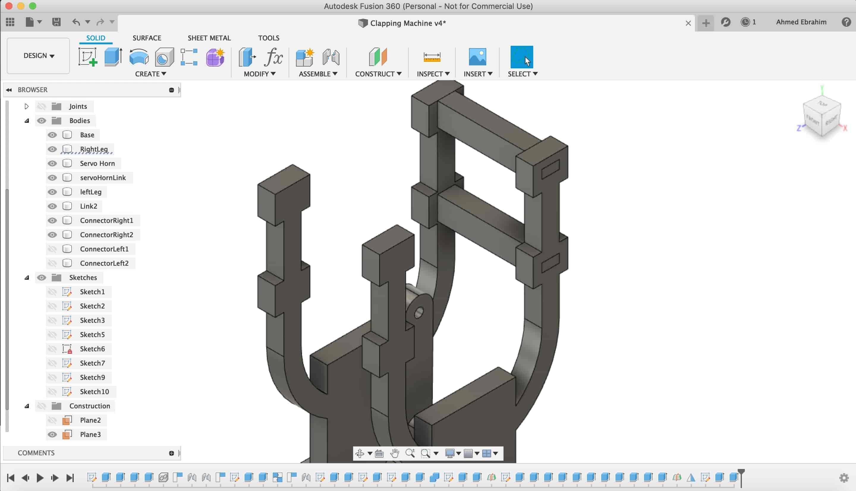
Then, I made those two links.
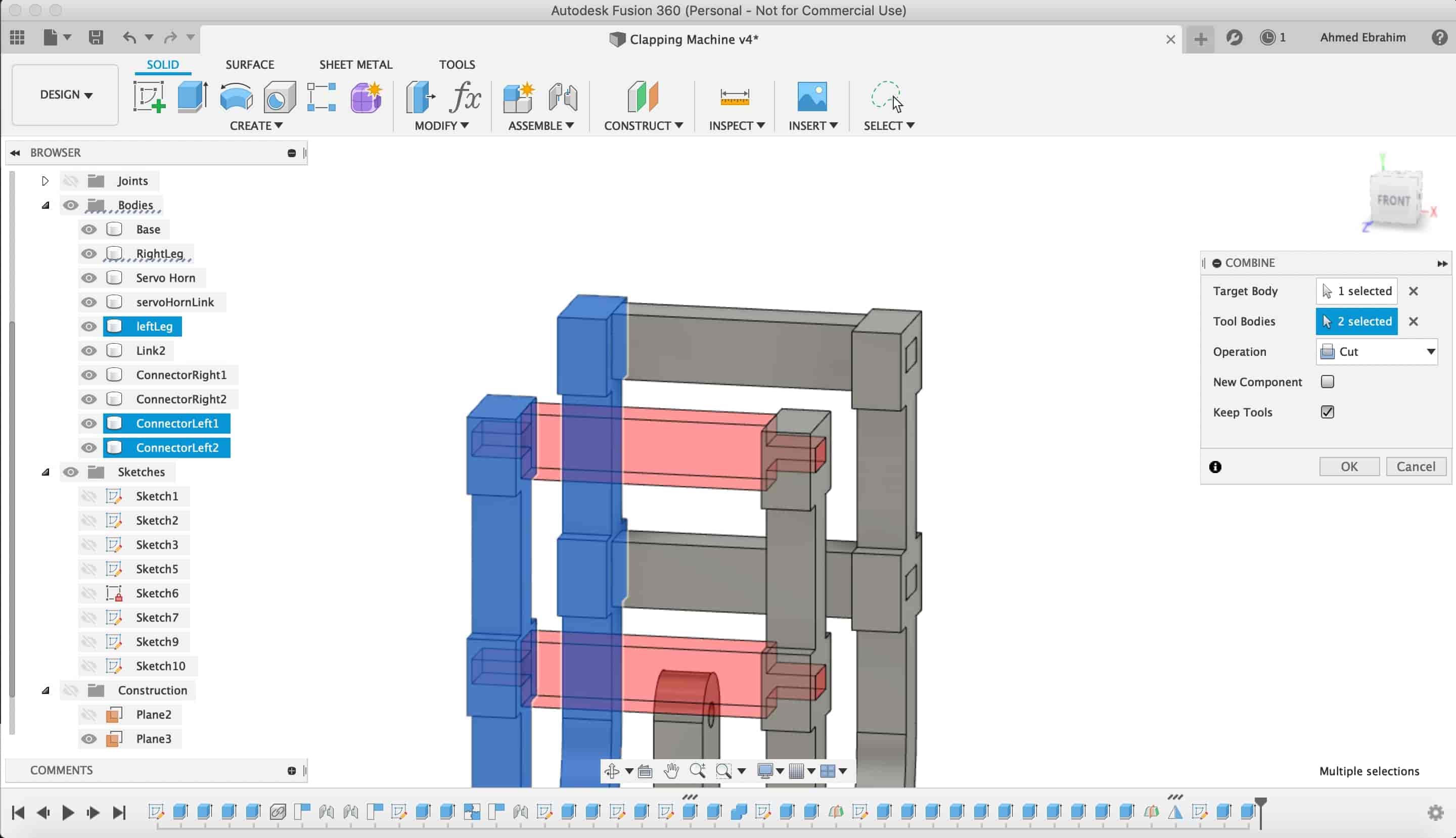
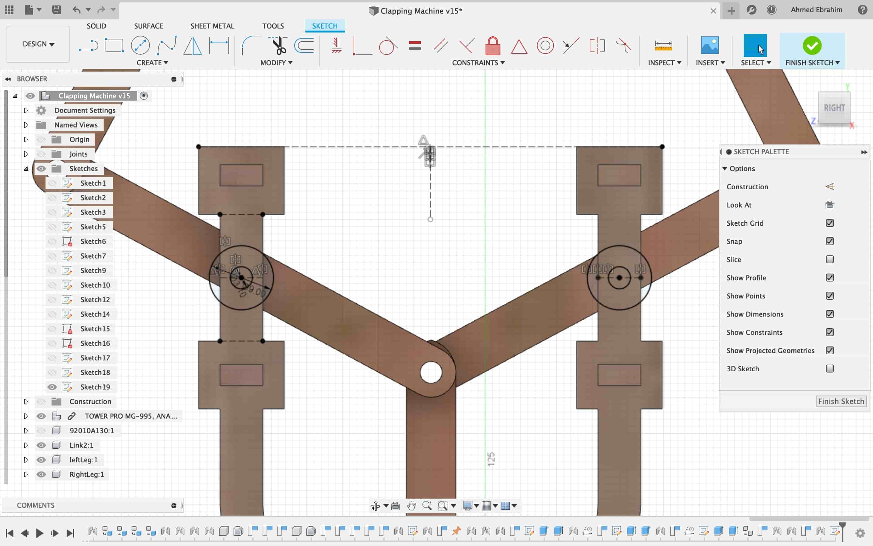
Now, we wanna fix these links with the front and back faces. but, as a revolute joint not as a rigid joint. We created a sketch on that face.
Draw a 3.1mm circle and extruded it as "cut" in the body
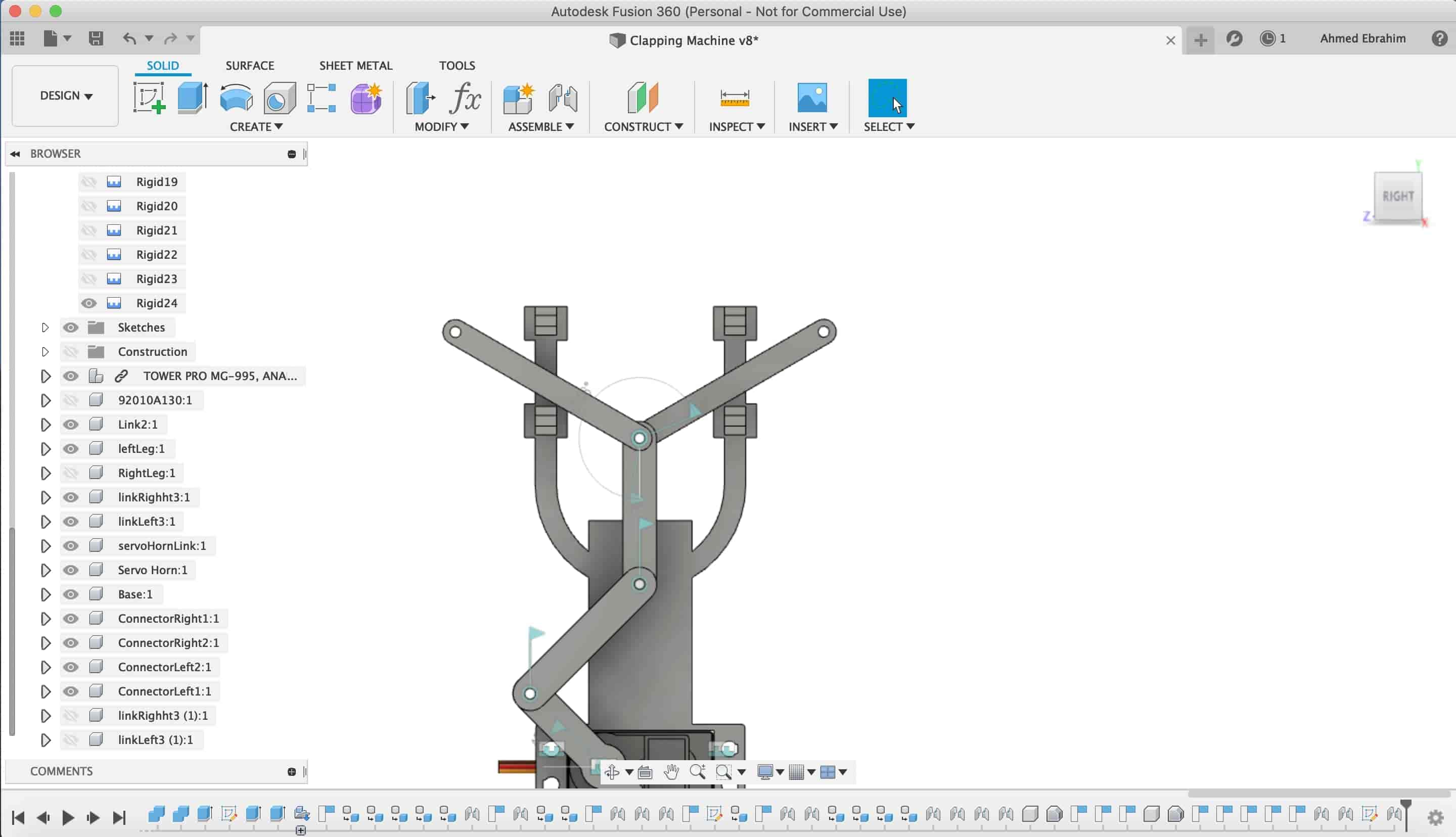
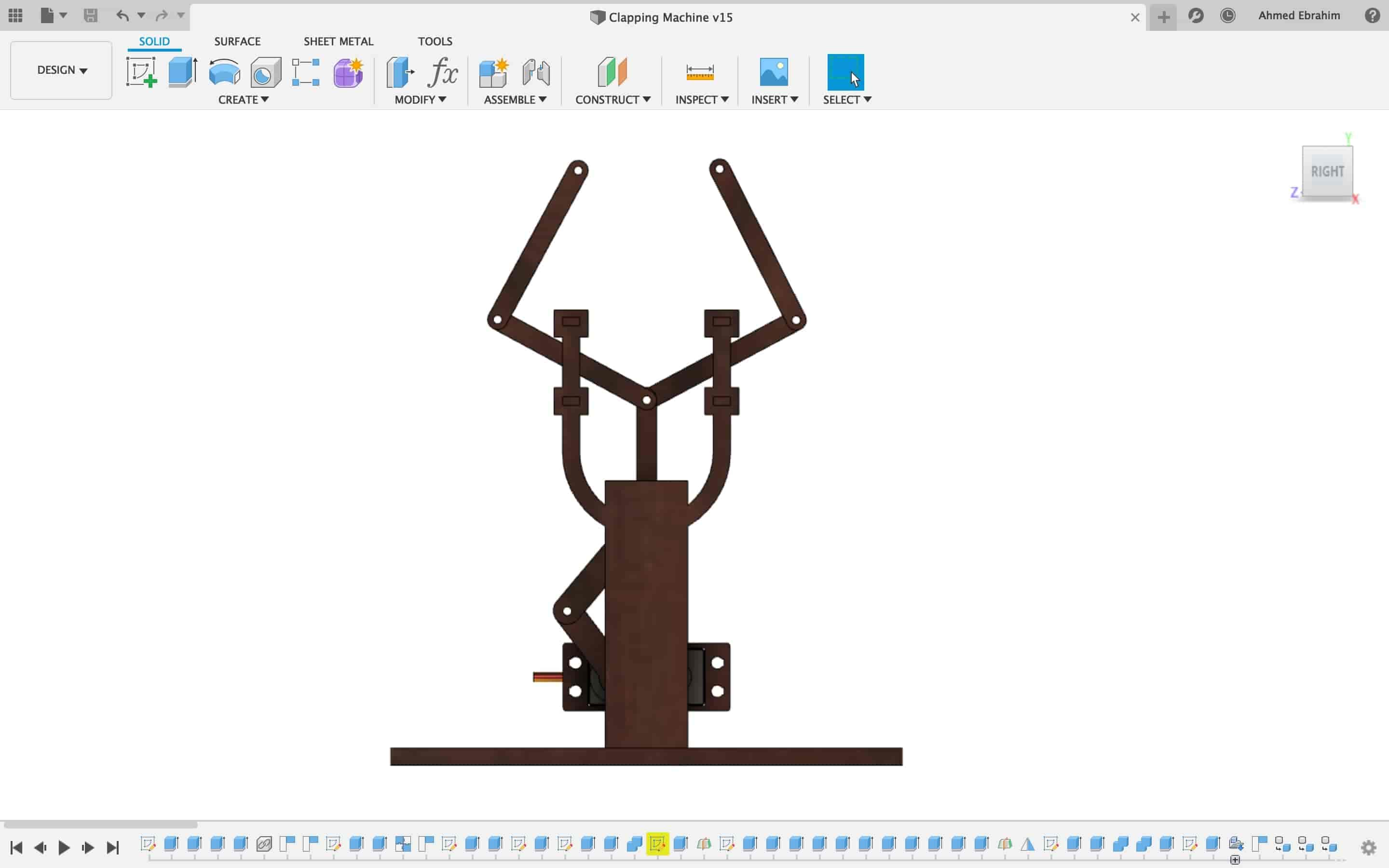
Fusion360 Animation
Fusion360 Motion Simulation Trial
Actually, I tried so hard to make a right functional simulation but it seems like i'm failed. I have some problems with the joints and motion links in fusion360. but I will work on fixing that problem in the upcoming days.