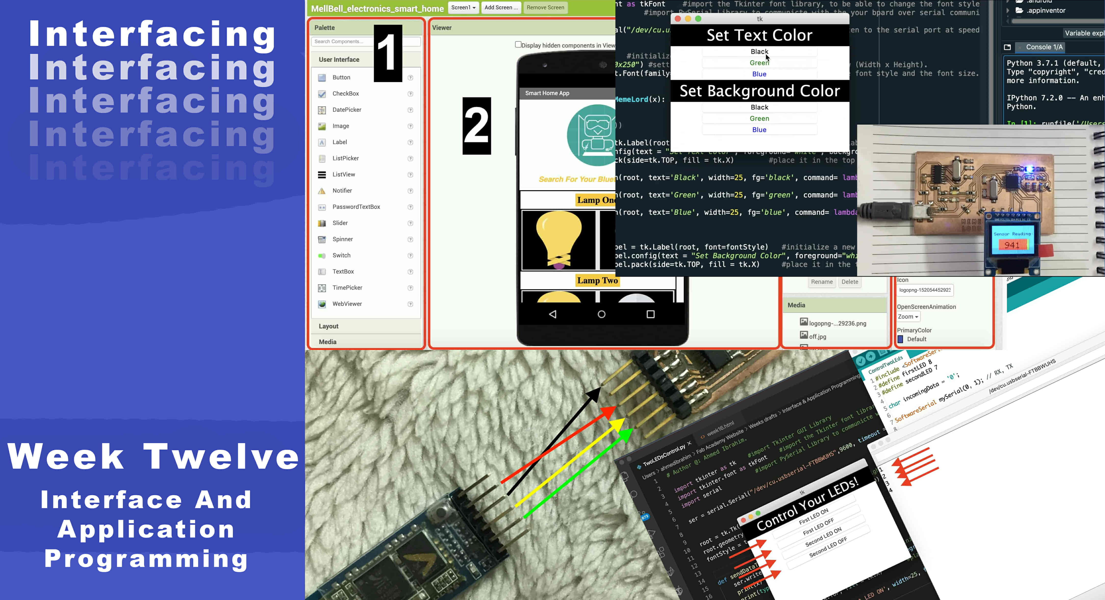
Interface And Application Programming
What’s Going On?
Today is the Interfacing and user interaction day! This week, we need to build a user interface that allows the user to control an output/input device. We need that user interface to be user-friendly and as easy to use as possible. I love Python, so I think that I will use Python and the Tkinter module to build a cool GUI(Graphical User Interface). Also, I will need to use the PySerial module to establish a Serial communication between my very expensive Mac book pro and my control boards.
At the end of the day, I need to play around with the Bluetooth module, I wanna control some LEDs from my mobile phone over the Bluetooth communication that gonna be fun.
Controlling Some LEDs from a Python-Made GUI
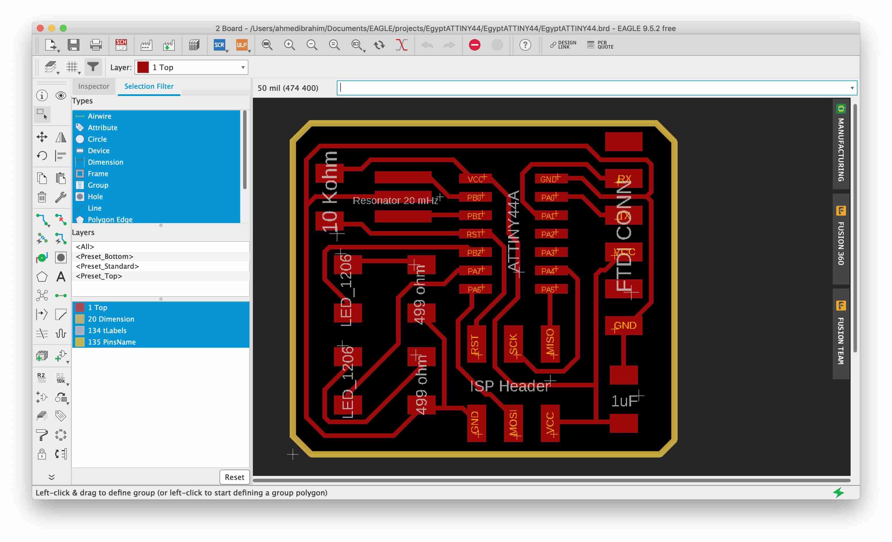
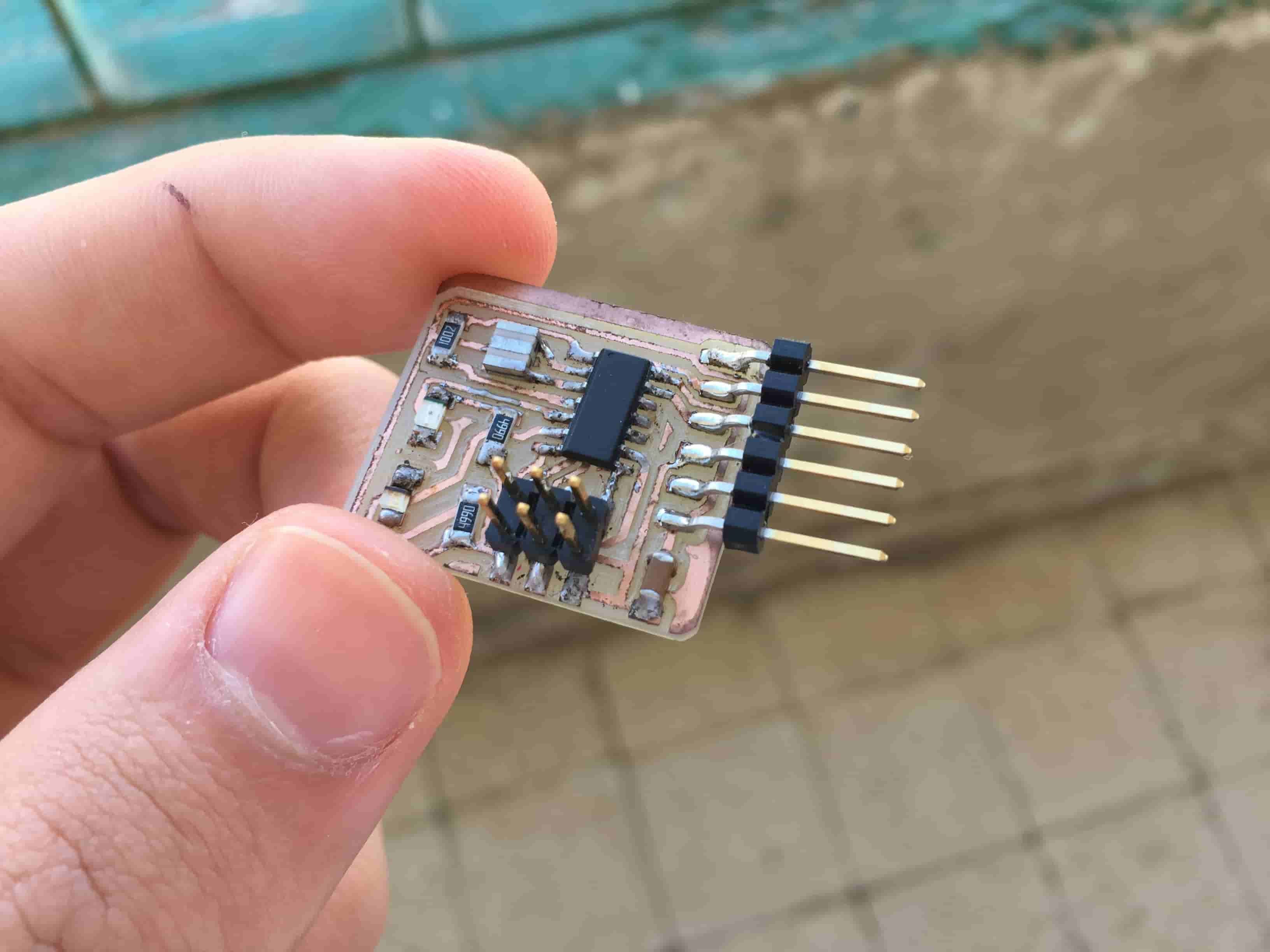
In this small project, we need to control two different color LEDs from my a Python-made GUI(Graphical User Interface). To build the GUI, I used Python and Tkinter. And to establish the Serial communication, I Used the PySerial Python module. I heard you, we need a board to control! So, I used the Attiny44 board that I designed in the Electronics Production Week.
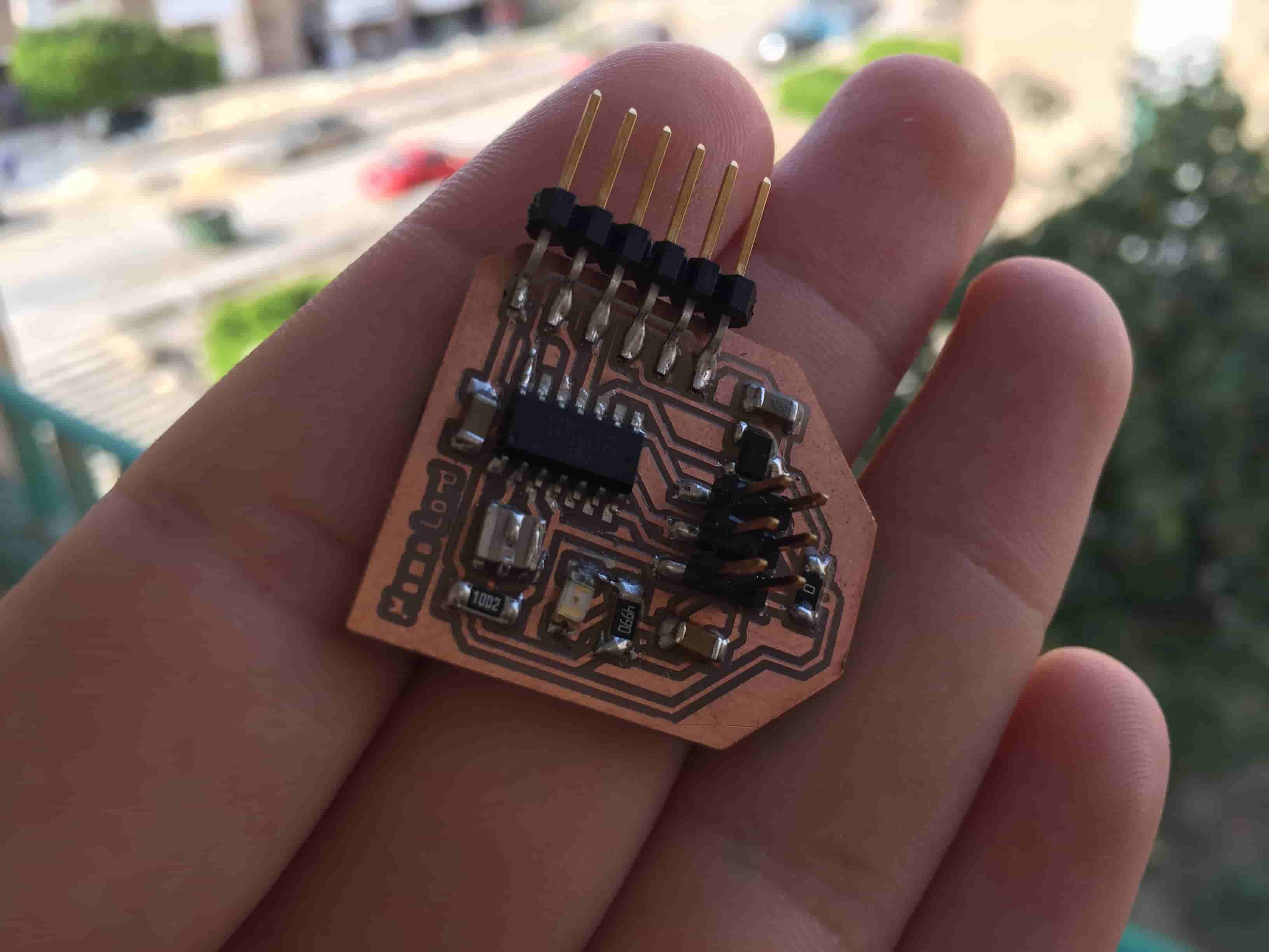
The board is pretty simple, it has two different LEDs, the first LED is connected to the Attiny44 pin PB2(Arduino D8). And, the second LED is connected to the Attiny44 pin PA7(Arduino D7). I’m using an external 20MHz resonator. And, an FTDI pin header to be able to connect the FTDI cable to the board to provide it with power and to serially communicate with it. Also, there’s an ISP Programmer pin header to be able to connect out programmer and upload the code to it. You can download the Board fabrication files from the Electronics Production Week.
The Interesting part, I wanna write a Python GUI program that controls the board two LEDs. Attiny44 board and the Python GUI are connected and talking to each other via the Serial port. I will use the famous Tkinter python module to build my GUI program. And to establish the Serial communication between the GUI and theAttiny44 board we are gonna use the PySerial module. To be able to use the Serial communication with Python you have to install the PySerial library, it doesn’t come by default with Python. Here’s a link showing how to install PySerial. And here’s a link too showing how to install Tkinter in case you don’t have it on your machine.
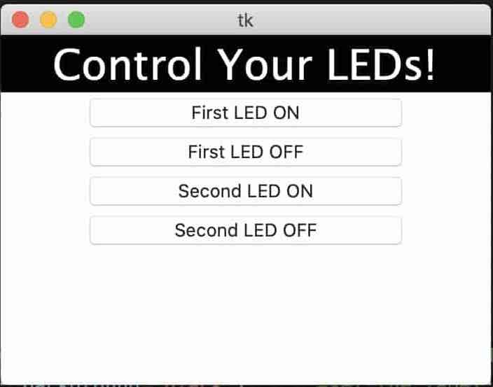
I like to start small to make the debugging process easier. So, I started with building the app GUI and test that all the buttons are working correctly without problems before writing any Serial communication code. I designed a simple GUI, it has one label and four buttons. Two buttons to control the first LED on and off. And the other two LEDs to control the second LED on and off.
# Author @: Ahmed Ibrahim.

import tkinter as tk    #import Tkinter GUI Library
import tkinter.font as tkFont    #import the Tkinter font library, to be able to change the font style and font size.
import serial           #import PySerial Library to communicte with the your board over serial communication(Tx, Rx)

ser = serial.Serial("/dev/cu.usbserial-FTBBWUHS",9600, timeout = 1)  # listen to the serial port at speed 9600.


root = tk.Tk()      #initialize a new window
root.geometry("350x250") #setting the width and the height of the window (Width x Height).
fontStyle = tkFont.Font(family="Lucida Grande", size=30)    #setting the font style and the font size.


def sendDataToTheMemeLord(x):
    print(x)
    print(type(x))

textColorLabel = tk.Label(root, font=fontStyle)      #initialize a new label with the font style we initialezed before.
textColorLabel.config(text = "Control Your LEDs!", foreground="white", background="black")      #set the label name "Control Your LEDs!". set the background color of the label to black, and the text color to white.
textColorLabel.pack(side=tk.TOP, fill = tk.X)        #place it in the top side of the window. and make it fill the width of the window.

button = tk.Button(root, text='First LED ON', width=25, fg='black', command= lambda: sendDataToTheMemeLord(b'1'))
button.pack()
button = tk.Button(root, text='First LED OFF', width=25, fg='green', command= lambda: sendDataToTheMemeLord(b'2'))
button.pack()
button = tk.Button(root, text='Second LED ON', width=25, fg='blue', command= lambda: sendDataToTheMemeLord(b'3'))
button.pack()
button = tk.Button(root, text='Second LED OFF', width=25, fg='blue', command= lambda: sendDataToTheMemeLord(b'4'))
button.pack()

root.mainloop()
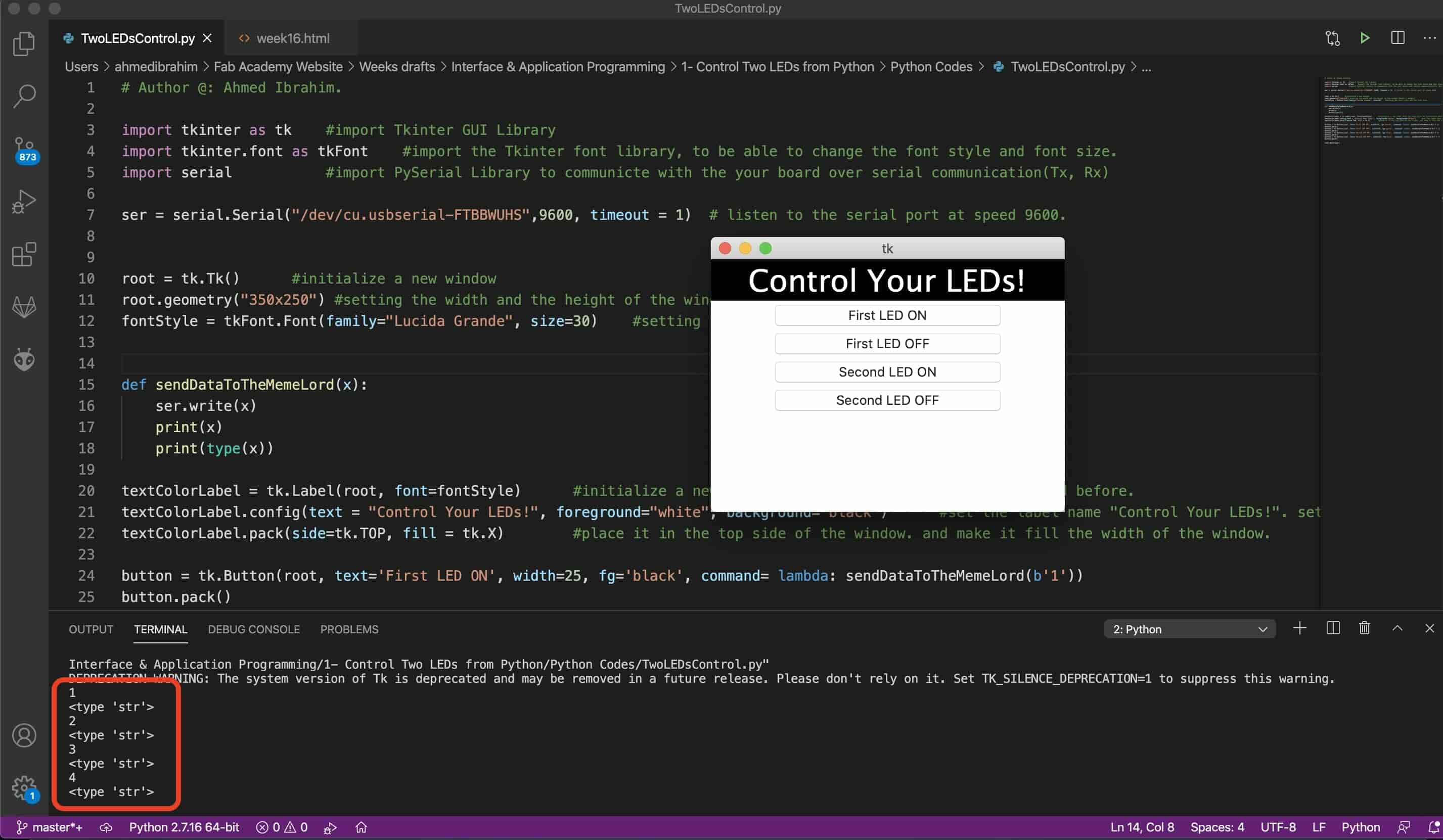
When I press any button from the four buttons, it triggers the sendDataToTheMemeLord(x) which takes one argument x, this argument x is the data that will be sent to the Attiny44 board over the Serial port. Each button passes a different value to the sendDataToTheMemeLord(x) argument. Like the “First LED ON” button will send value 1. the “First LED OFF” button will send value 2. And so on... Words are great! but we need to test that script if it’s working or not, So I told my script when I press any button from these four buttons, print the data which the pressed button passed to the sendDataToTheMemeLord(x) function on the terminal. And that went great!
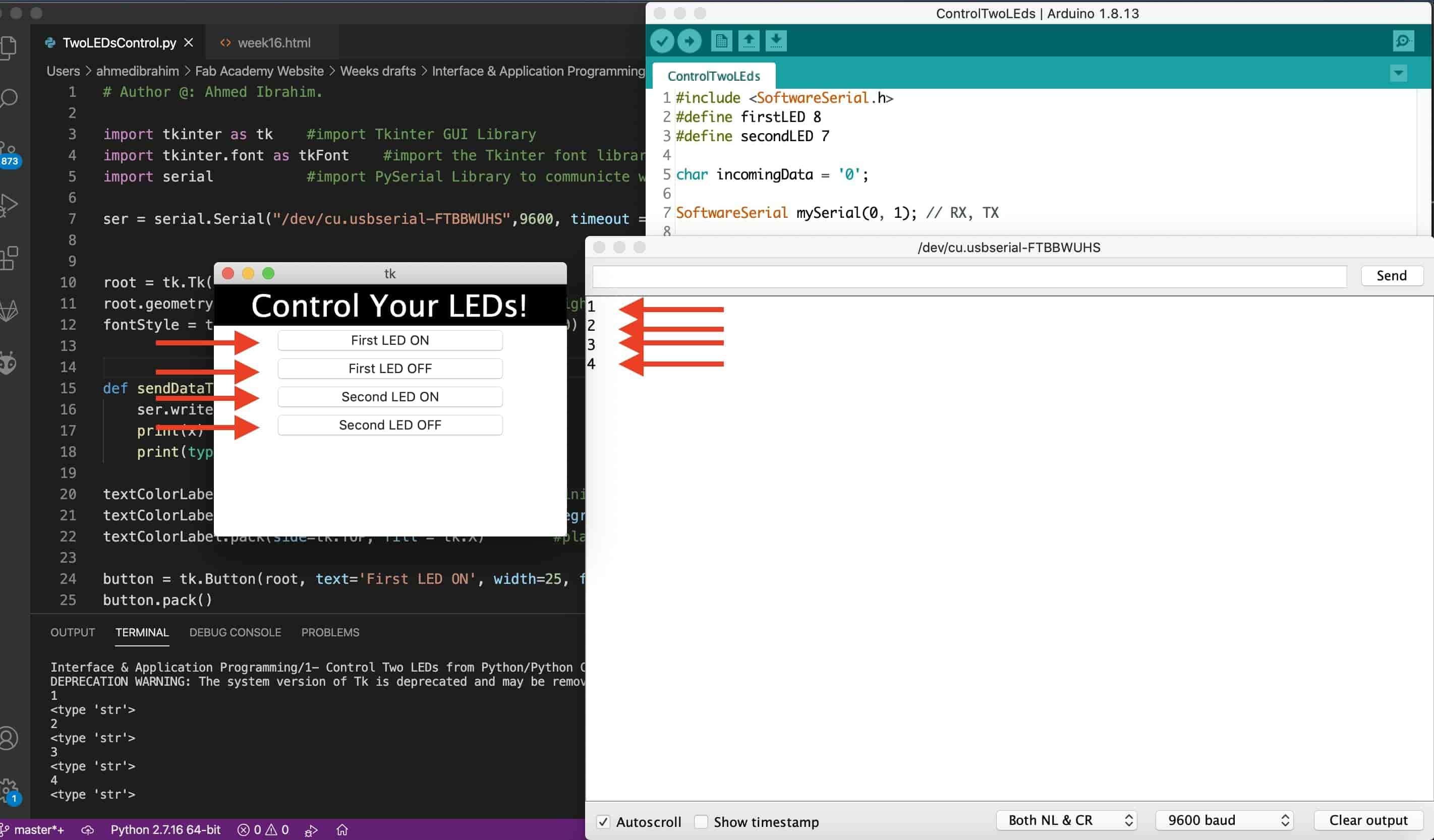
The next step is to send that data to the Attiny44 board over the Serial port. As I stated before, I’m using the PySerial module to establish a serial communication between the Python GUI app and the Attiny44 board. After the Attiny44 board receives that data it will change the two LEDs states accordingly. But first, I wanna make sure that the data is traveling from the Python GUI to the Attiny44 board correctly without problems. So, in the Python code, I’m using the PySerial .write() function to send a one byte char to the Attiny44 board over the Serial port. And in the C code, I’m reading that one byte data and printing it in the Arduino IDE Serial monitor. And it went great again!
#include <SoftwareSerial.h>
#define firstLED 8
#define secondLED 7

char incomingData = '0';

SoftwareSerial mySerial(0, 1); // RX, TX

void setup() {
    mySerial.begin(9600);
    pinMode(firstLED, OUTPUT);
    pinMode(secondLED, OUTPUT);
}


void loop() {
    while (mySerial.available() > 0) {
    incomingData = mySerial.read();
    mySerial.println(incomingData);
    delay(10);
    }

}
        # Author @: Ahmed Ibrahim.

        import tkinter as tk    #import Tkinter GUI Library
        import tkinter.font as tkFont    #import the Tkinter font library, to be able to change the font style and font size.
        import serial           #import PySerial Library to communicte with the your board over serial communication(Tx, Rx)

        ser = serial.Serial("/dev/cu.usbserial-FTBBWUHS",9600, timeout = 1)  # listen to the serial port at speed 9600.


        root = tk.Tk()      #initialize a new window
        root.geometry("350x250") #setting the width and the height of the window (Width x Height).
        fontStyle = tkFont.Font(family="Lucida Grande", size=30)    #setting the font style and the font size.


        def sendDataToTheMemeLord(x):
            ser.write(x)
            print(x)
            print(type(x))

        textColorLabel = tk.Label(root, font=fontStyle)      #initialize a new label with the font style we initialezed before.
        textColorLabel.config(text = "Control Your LEDs!", foreground="white", background="black")      #set the label name "Control Your LEDs!". set the background color of the label to black, and the text color to white.
        textColorLabel.pack(side=tk.TOP, fill = tk.X)        #place it in the top side of the window. and make it fill the width of the window.

        button = tk.Button(root, text='First LED ON', width=25, fg='black', command= lambda: sendDataToTheMemeLord(b'1'))
        button.pack()
        button = tk.Button(root, text='First LED OFF', width=25, fg='green', command= lambda: sendDataToTheMemeLord(b'2'))
        button.pack()
        button = tk.Button(root, text='Second LED ON', width=25, fg='blue', command= lambda: sendDataToTheMemeLord(b'3'))
        button.pack()
        button = tk.Button(root, text='Second LED OFF', width=25, fg='blue', command= lambda: sendDataToTheMemeLord(b'4'))
        button.pack()

        root.mainloop()
We are up to the final part of this small project, the Attiny44 board is now is receiving the data from the Python GUI app correctly, right! Let's take some actions tho. We will slightly modify our C code by adding if-conditions that checks what are the data coming from the python app, according to the received data it will take different actions. If it received character “1” it will turn on the first LED, if it received character “2” it will turn the first LED off, and so on…
            #include <SoftwareSerial.h>
            #define firstLED 8
            #define secondLED 7

            char incomingData = '0';

            SoftwareSerial mySerial(0, 1); // RX, TX

            void setup() {
            mySerial.begin(9600);
            pinMode(firstLED, OUTPUT);
            pinMode(secondLED, OUTPUT);
            }


            void loop() {
            while (mySerial.available() > 0) {
            incomingData = mySerial.read();
            mySerial.println(incomingData);
            if (incomingData == '1') {
                digitalWrite(firstLED, HIGH);
            }
            else if (incomingData == '2') {
                digitalWrite(firstLED, LOW);
            }
            else if (incomingData == '3') {
                digitalWrite(secondLED, HIGH);
            }
            else if (incomingData == '4') {
                digitalWrite(secondLED, LOW);
            }
            delay(10);
            }

            }
Control Some LEDs From A Mobile App over Bluetooth
MIT App Inventor is a visual programming environment that allows everyone -even children- to build fully functional Android mobile apps. To build your mobile app using the MIT app inventor tool, you just need to design the app UI(User interface) using some premade blocks, then make the program logic and give some functions to your UI(User interface) components also by using some premade blocks.
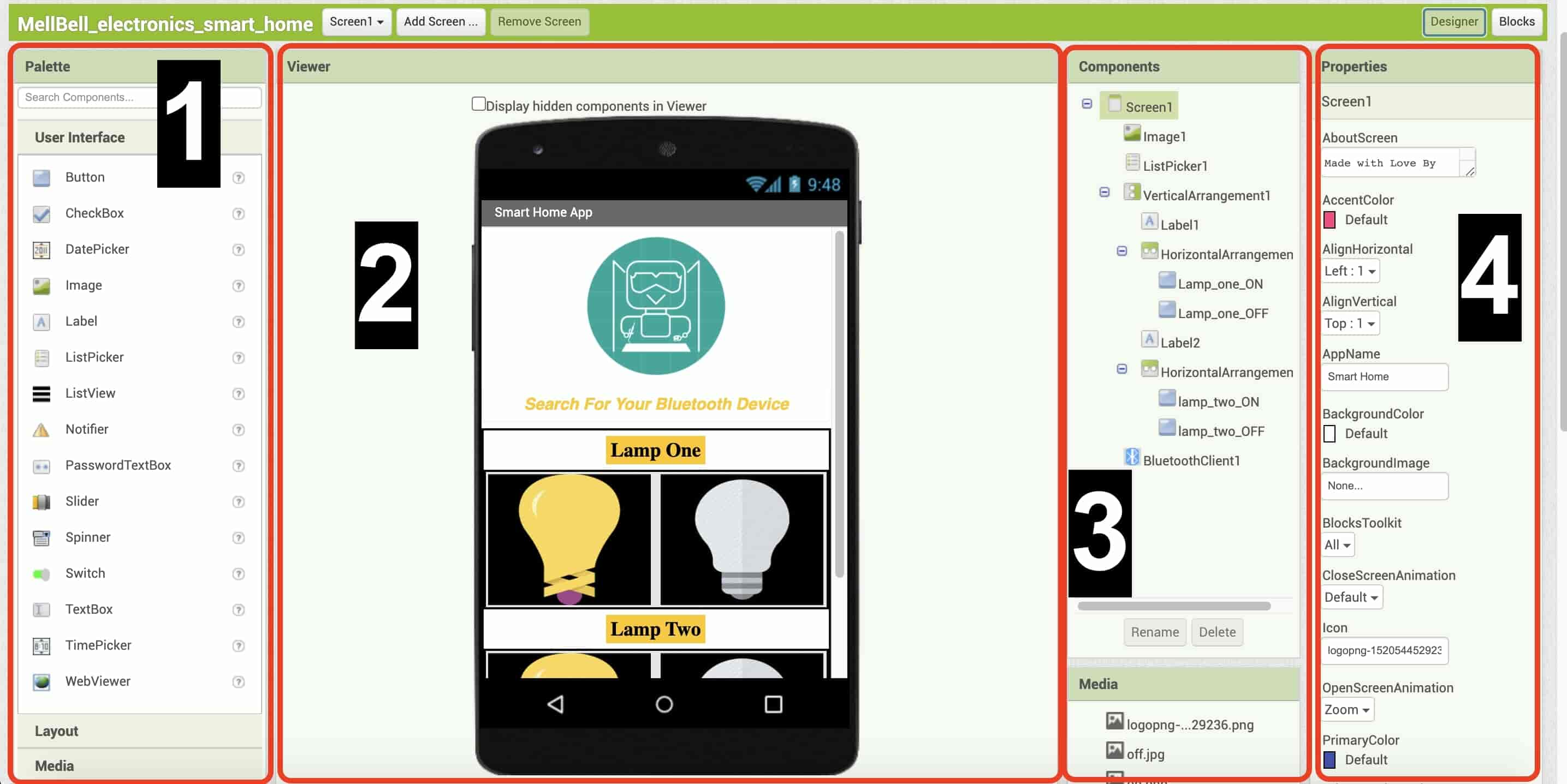
- From the palette toolbar, where you select components(like buttons, radios, labels, images, ...) to use it in your app. To add any component inside your app UI, just make a simple drag and drop.
- From the viewer workspace, here is a preview for how your app UI screen.
- From the components toolbar, you can see the hierarchy of the UI components that you are using in your app. Also, you can rename, edit, delete your components.
- From the properties toolbar, you can edit the properties of a specific component, like changing the text color, text font, button text, and so on…
After building the app UI, we need to build the logic of the app, how do those UI components will behave and if we want to make the app somehow interactive and make some animations or something, we’re gonna do that in the blocks workspace.
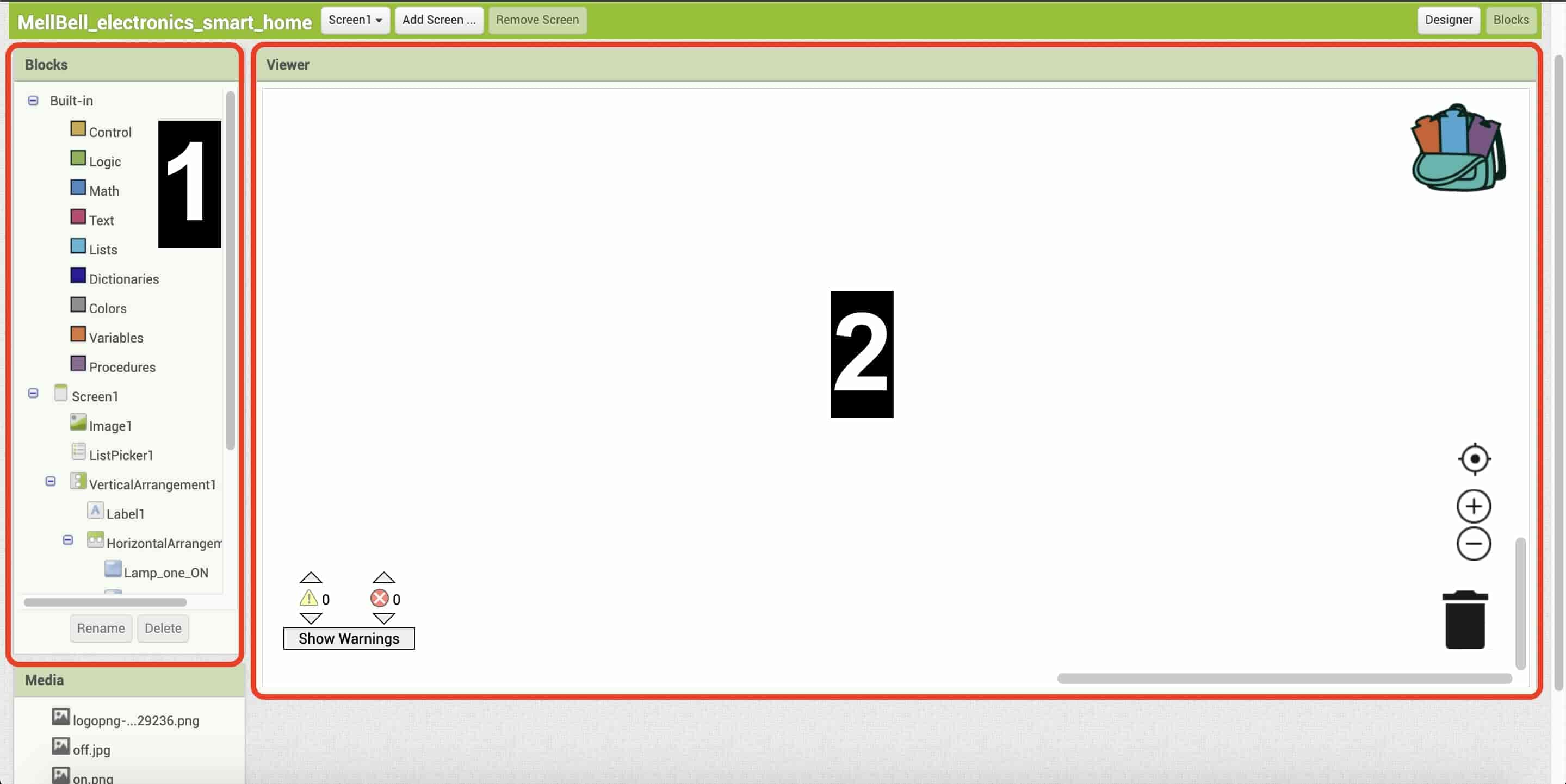
- the blocks toolbar contains all the premade blocks that you will use to make the app logic. Like the If conditions, while loops, comparison operators, and so on …
- In the viewer workspace, you should assemble the program blocks that specify how the components should behave. You assemble blocks visually by the dragging and drop method.
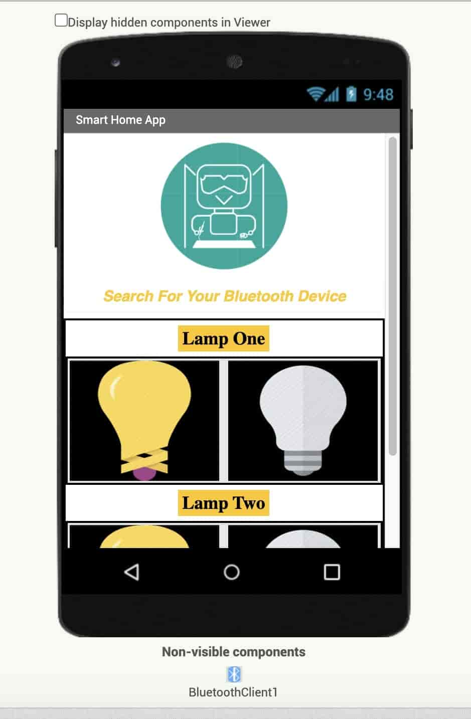
Now, let’s start designing the app user interface that will contain some buttons, labels, images to allow the user to control the two LEDs wirelessly. Open a new project, and I started inserting my UI components into my app. I’m using:
On the top of the screen, I’m using an image for my website, because I love it <3, One list picker, (search for your Bluetooth device) when press on this sentence it will open a menu with the paired Bluetooth devices that we will choose the HC-05 Bluetooth device to connect with,
And two labels, (“Lamp One”, “Lamp Two”) as indicators telling the user that “Lamp One” section is for the first LED and the “Lamp Two” section for the second LED, 4 image buttons (2 bright lamps, two dark lamps), any button you press on it, will send a specific number to the Attiny44 board, and Finally, Adding the Bluetooth client component, to allow the app to use the Bluetooth connection of the mobile. It’s very important to add.
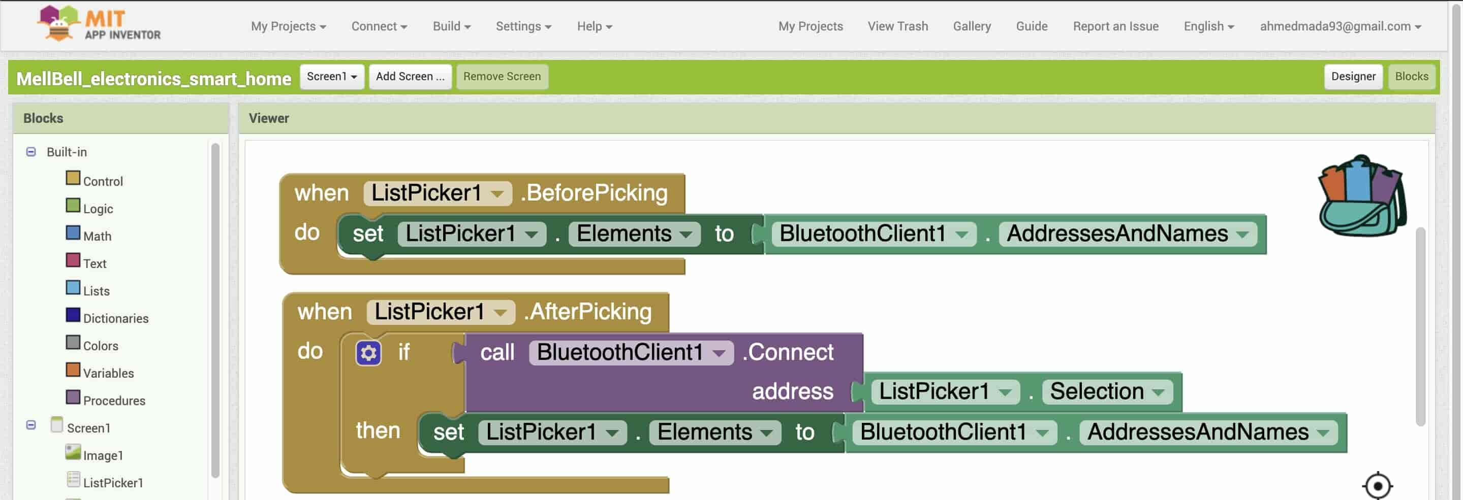
- Before clicking and opening the list picker menu, add all the Bluetooth pairing devices in this menu elements, to easily select one device to connect with.
- After clicking and opening the list picker menu, connect to the selected device from this menu elements, then update these menu elements again and add all the pairing Bluetooth devices.
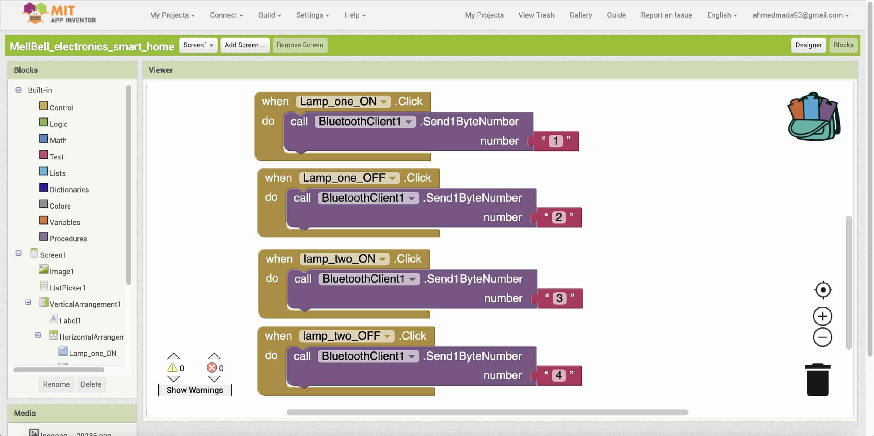
- When the lamp one bright lamp image button is clicked send one-byte number “1” to the connected Bluetooth device, then the Attiny44 board will receive this number and will turn the first LED on.
- When the lamp one dark lamp image button is clicked send one-byte number “2” to the connected Bluetooth device. then the Attiny44 board will receive this number and will turn the first LED off.
- When the lamp two bright lamp image button is clicked send one-byte number “3” to the connected Bluetooth device. then the Attiny44 boardICO will receive this number and will turn the second LED on.
- When the lamp two dark lamp image button is clicked send one-byte number “4” to the connected Bluetooth device. then the Attiny44 board will receive this number and will turn the second LED off.
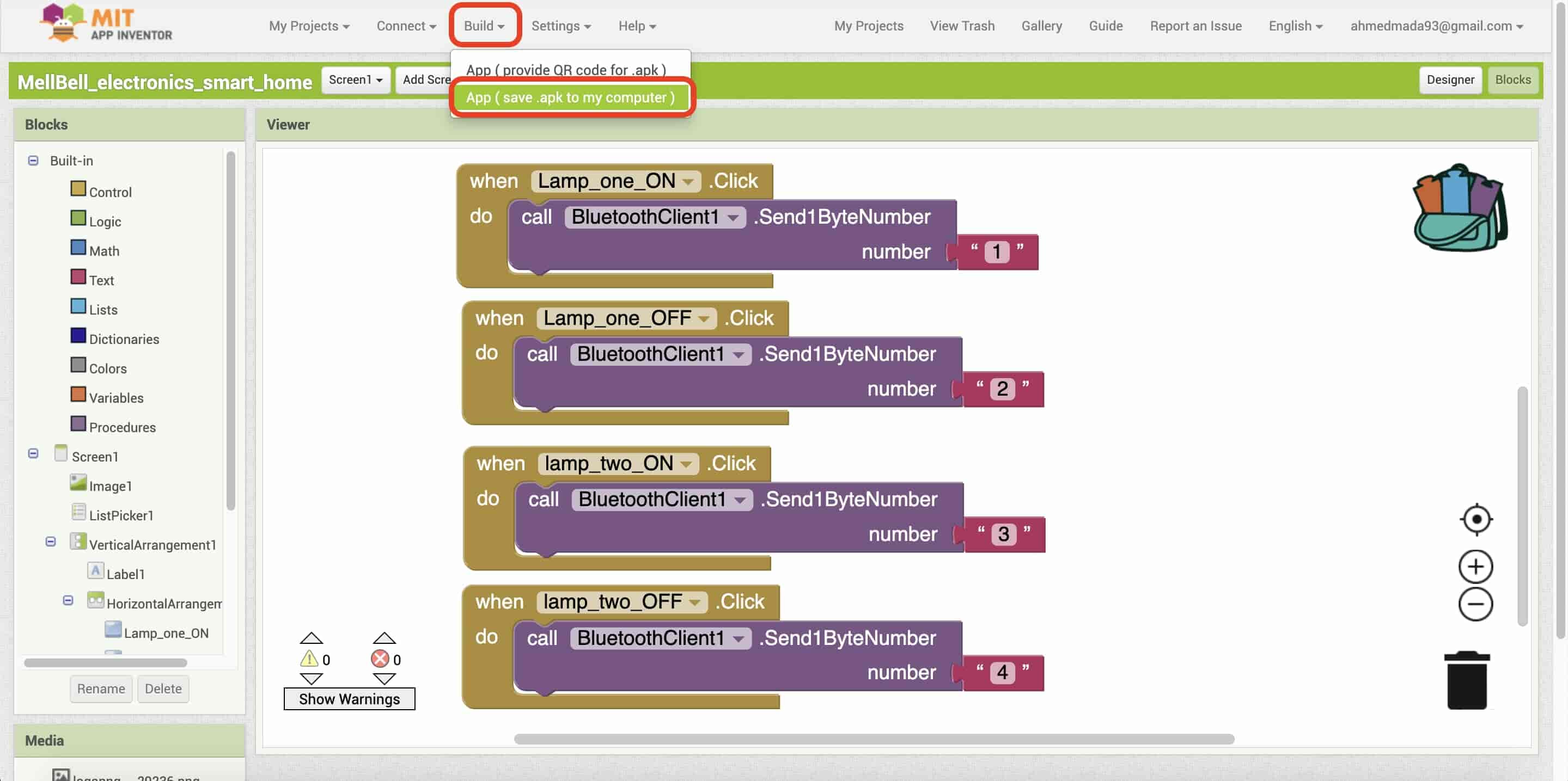
After finishing the mobile app, we need to export the APK file to install the app on the Android mobile phone. From the Build → App(Save .apk to my computer). Then transfer that APK file to your mobile phone and install the app. That’s it!
In order to talk with the Attiny44 board wirelessly without any physical interaction, we need a component that able to send and receive data wirelessly, here is the Bluetooth module HC-05 role.
Let’s take a closer look at the HC-05 Bluetooth module, this awesome device can work as a slave and master which means that it can send or receive data, it can make a connection between two different Attiny44 boards which allows the Attiny44 boards to talk to each other wirelessly. Also, it’s very easy to wire with any microcontroller because it’s an SPP(Serial Port Protocol) Bluetooth module which means it connects with the microcontroller via the Serial communication (Tx, Rx). Let’s take a look at the HC-05 pinout.
- EN or KEY → if brought HIGH before power is applied, forces the AT commands setup mode.
- VCC → +5 power.
- GND → negative.
- Tx → transmits the data from the HC-05 module to the microcontroller Serial receive.
- Rx → Receive Serial data from the microcontroller Serial transmit.
- State → tells if connected or not.
Connecting the HC-05 bluetooth module to the Attiny44 board is not that hard.
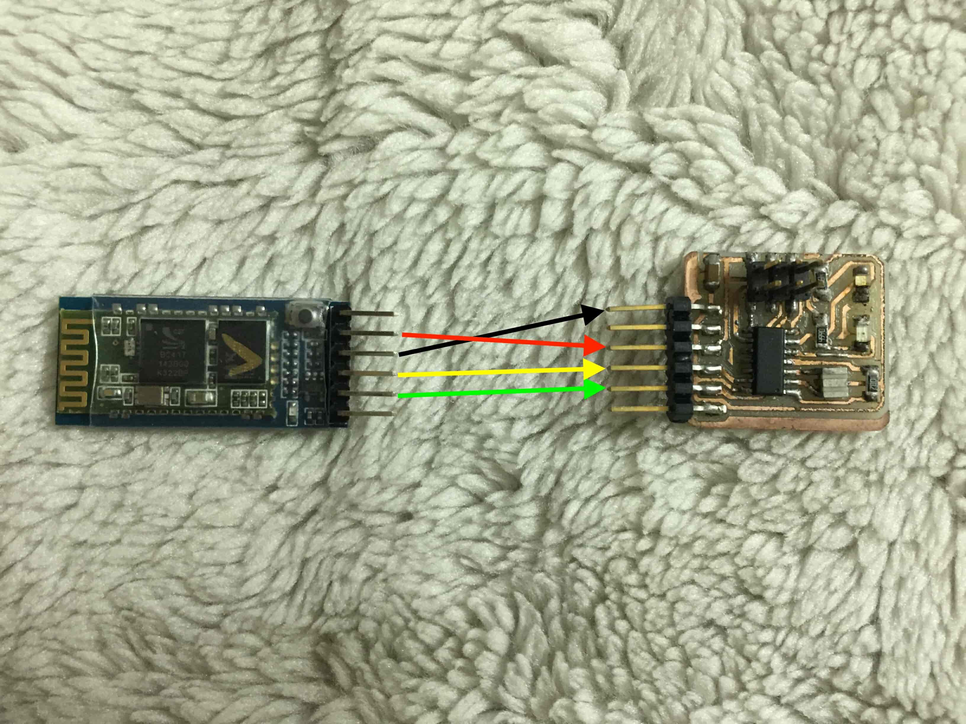
| Attiny Board | HC-05 |
|---|---|
| VCC | 5V |
| GND | GND |
| Tx | Rx |
| Rx | Tx |
After connecting the HC-05 Bluetooth module device with the Attiny44 board, let’s edit the last Arduino code a lil bit.
#include <SoftwareSerial.h>
#define firstLED 8
#define secondLED 7

int incomingData = 0;

SoftwareSerial mySerial(0, 1); // RX, TX

void setup() {
mySerial.begin(9600);
pinMode(firstLED, OUTPUT);
pinMode(secondLED, OUTPUT);
}


void loop() {
while (mySerial.available() > 0) {
incomingData = mySerial.read();
mySerial.println(incomingData);
if (incomingData == 1) {
    digitalWrite(firstLED, HIGH);
}
else if (incomingData == 2) {
    digitalWrite(firstLED, LOW);
}
else if (incomingData == 3) {
    digitalWrite(secondLED, HIGH);
}
else if (incomingData == 4) {
    digitalWrite(secondLED, LOW);
}
delay(10);
}

}
The C code is very simple, we are using the SoftwareSerial library which comes pre installed with the Arduino IDE. The Arduino hardware has built-in support for serial communication on pins 0 and 1 (which also goes to the computer via the USB connection). The native serial support happens via a piece of hardware (built into the chip) called a UART. This hardware allows the Atmega chip to receive serial communication even while working on other tasks. The SoftwareSerial library has been developed to allow serial communication on other digital pins of the Arduino, using software to replicate the functionality (hence the name "SoftwareSerial"). It is possible to have multiple software serial ports with speeds up to 115200 bps. A parameter enables inverted signaling for devices which require that protocol.
We only edited the “incomingData” variable type from a character type into an integer type. Because the mobile app is sending a one byte integer value. That’s it!
Mobile App Source Files
Display a Hall Effect Sensor Data On A GUI
In the Input devices week, I designed an Attiny44 board that has a hall effect sensor on it, I built a GUI using Python and Tkinter. And I established a serial communication between the Attiny44 board and the Python GUI through an FTDI cable. And to make the Python GUI able to communicate serially, I used the PySerial python module. For more details and explanation please visit the Input devices week.
Arduino Code
                #include <SoftwareSerial.h>
                    #define hallEffectSensor A3
                    SoftwareSerial mySerial(2, 1); // RX, TX
                    void setup() {
                      mySerial.begin(9600);
                      pinMode(hallEffectSensor, INPUT);
                    }


                    void loop() {
                      int sensorReading = analogRead(hallEffectSensor);
                      mySerial.println(sensorReading);
                      delay(10);
                    }
Python Program
        # Author @: Ahmed Ibrahim.

        import tkinter as tk    #import Tkinter GUI Library
        import tkinter.font as tkFont    #import the Tkinter font library, to be able to change the font style and font size.
        import serial           #import PySerial Library to communicte with the your bpard over serial communication(Tx, Rx)

        ser = serial.Serial("/dev/cu.usbserial-FTBBWUHS",9600, timeout = 1)  # listen to the serial port at speed 9600.


        root = tk.Tk()      #initialize a new window
        root.geometry("1100x400") #setting the width and the height of the window (Width x Height).
        fontStyle = tkFont.Font(family="Lucida Grande", size=30)    #setting the font style and the font size.


        label = tk.Label(root, font=fontStyle)      #initialize a new label with the font style we initialezed before.
        label.pack(side=tk.TOP, fill = tk.X)        #place it in the top side of the window. and make it fill the width of the window.

        sensorReading = tk.Label(root, font=fontStyle)   #initialize a new label with the font style we initialezed before.
        sensorReading.pack(side=tk.TOP, fill = tk.X)     #place it in the top side of the window. and make it fill the width of the window.

        frame1 = tk.Frame(master=root, width = 500, height=200, bg="red")  #initialize a new frame with a red color.
        frame1.pack()


        while(True):                                                        # the main program (infinity loop blocks anything come after it)

            reading = ser.readline().decode('ascii')                        # read the sensor data from the serial port, and decode it then store it inside the "reading" variable.

            sensorReading.config(text = reading, foreground="white", background="black")    #update the "sensorReading label" with the data stored inside the "reading" variable, set the background color of the label to black, and the text color to white.
            label.config(text = "Sensor Reading value is:    ", foreground="white", background="black")      #set the "sensorReading label" to "Sensor Reading value is:    ", set the background color of the label to black, and the text color to white.
            frame1.config(width = reading)    # update the red frame width according the data stored inside the "reading" variable.

            root.update_idletasks()
            root.update()
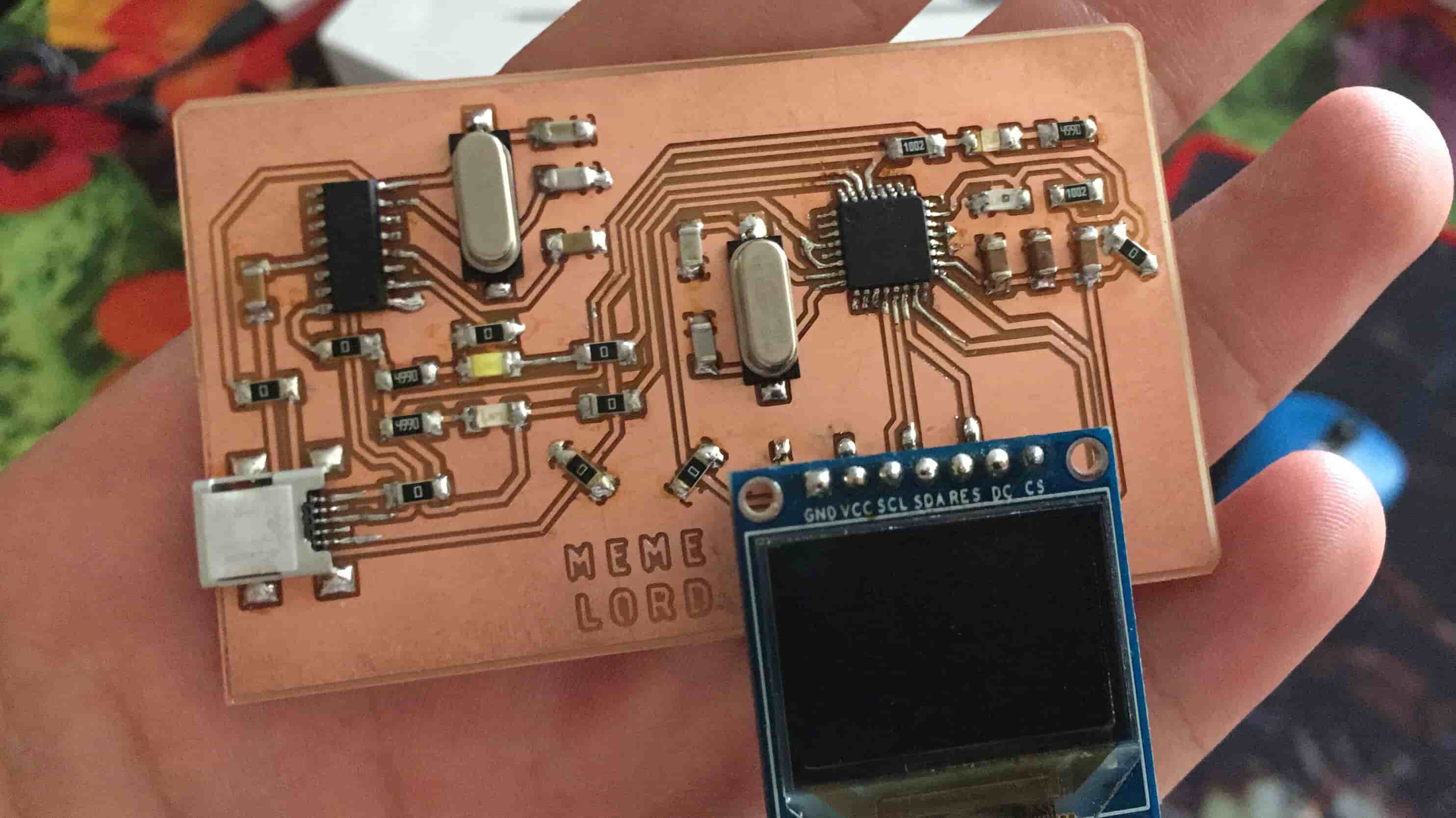
Control An OLED Screen Through A Python GUI
In the Embedded Programming Week, I also made an ATmega328P-AU board that is an Arduino compatible. That board, has an OLED screen and phototransistor sensor built-in. I made a Python GUI that can control the OLED screen background and text color. For more details and explanation please check it out!
Arduino Code
Python Program