Embedded Networking And Communication
What’s Going On?
I’m so excited about this week! It’s all about communications and networking. I need to build a network between two devices, there are many ways that you can use to achieve that like, I2C protocol, SPI protocol, and UART protocol. All of these methods are wired communication that needs a physical wire connecting these boards together(Serial Bus). But, these wired methods will not help if you are managing long-distance communication. For example, connecting a device in Egypt with another device in China. Here comes the power of wireless communication methods. In today’s assignment, I want to implement wireless communication between two different boards based on the Internet stack.
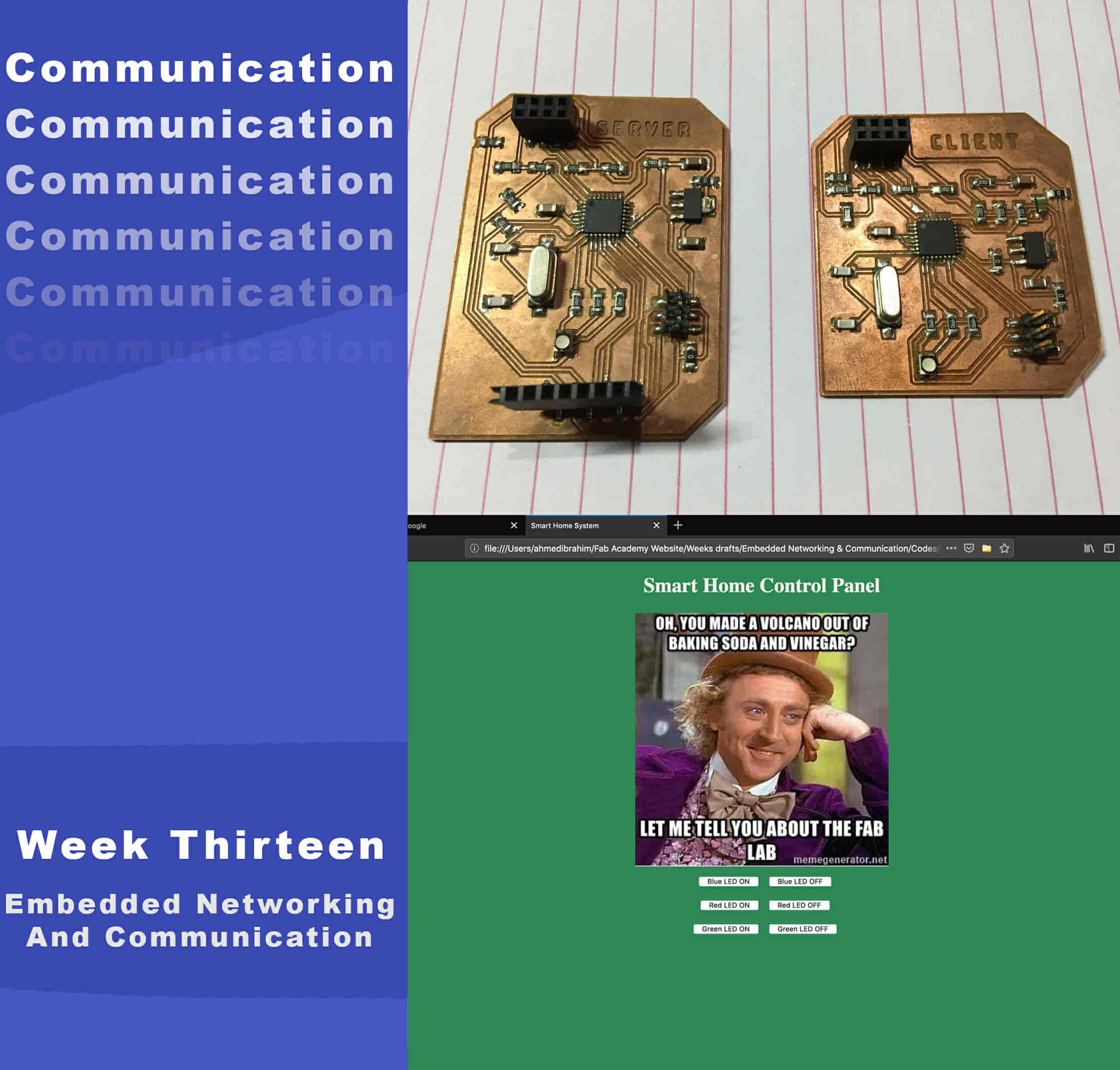
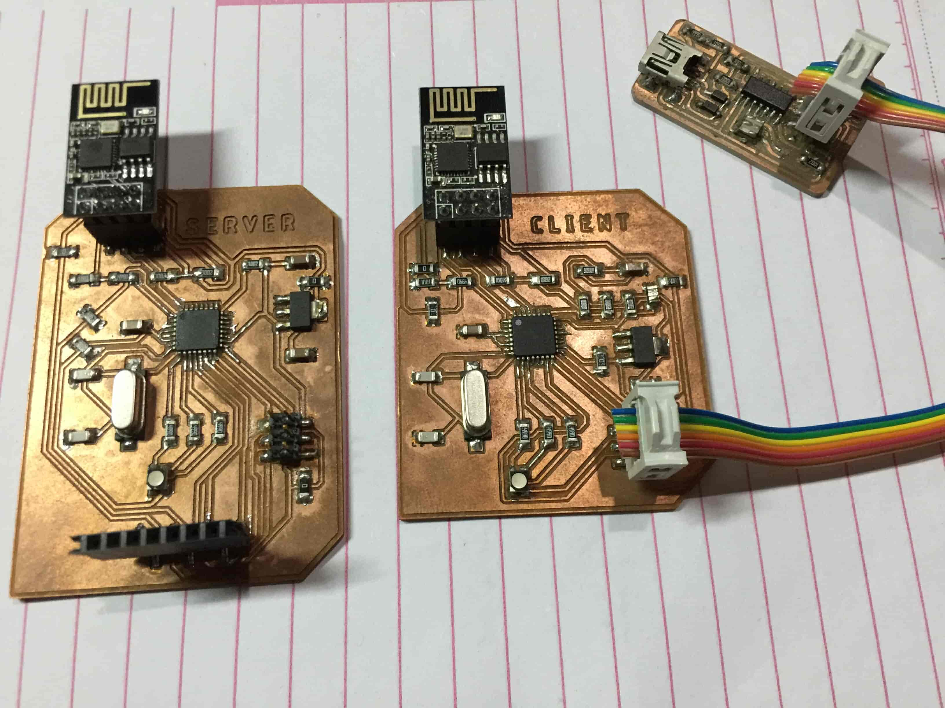
I have two ESP-01 modules In my inventory, So I decided to use them to build a network between two different boards. The first board has an ESP-01 module that is configured to work as a Server. The second board has another ESP-01 module that is configured to work as a Client and both these boards(Server and Client) are communicating together wirelessly over the Internet.
The Client board is based on the ATmega328p microcontroller, it contains a temperature sensor(NTC), one RGB LED, and of course one ESP-01 module. The ATmega328p microcontroller is sending AT commands to the ESP-01 module over the Serial bus(Tx, Rx) telling the ESP-01 what to do. The client board should send The temperature sensor(NTC) readings to the Server board which also contains an RGB LED and an OLED screen to display the received temperature sensor data on it.
To make things organized and more understandable, I divided this project into three sub-projects or sub-processes.
- The first part is making the Server board, sending some GET commands to it from a web browser, and test if it is receiving those commands correctly.
- After making sure that the server board is working fine, the second part is making the client board and send GET commands to the server board and see if the two boards(Server-Client) are communicating correctly or not.
Let’s know more about the ESP8266-01 Wifi module
The ESP8266-01 is very famous in the maker community. As a result, it has a very solid online community that you can find an answer to almost any question or problem you face with this awesome small module. iIts price is very cheap(around 1.5$), it’s very easy to use with the ATmega microcontroller or any microcontroller since it's a Serial wifi module it can communicate with the microcontroller chip over the serial bus. It has a built-in Microcontroller which means that you can use it as a standalone microcontroller and wifi module in one combo which is super cool. It has built-in two GPIOs that you can use to control some loads.
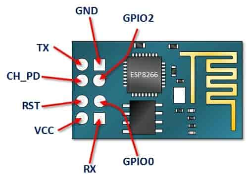
- VCC: connect to +3.3V power source. don’t connect it with a 5V source, the board will get damaged.
- GND: -ve pin, connect it to the ground of your circuit.
- CH_PD: chip enables pin – Active HIGH. connect it to a logic value HIGH to allow the module to boot up.
- RST: Chip Reset pin – Active LOW, when it pulled LOW it Resets the module. By default, this pin is connected to the HIGH logic value.
- GPIO0, GPIO2: General purpose input/output pins.
- Tx: connect to the Rx of the microcontroller(ATmega328) to establish serial communication.
- Rx: connect to the Tx of the microcontroller(ATmega328) to establish serial communication.
Before designing my PCB, I want to test my wiring and the code with an Arduino board on a breadboard to make sure that everything is working fine. Then, I will design my board according to that wiring.
ESP8266-01 Wifi Module Configuration
The ESP8266-01 module communicates with the ATmega microcontroller over the Serial communication, which means that we need to connect it with the ATmega Hardware Serial pins 0, 1(Tx, Rx). But in the future, I’m intending to add a CH340 USB to UART IC to be able to communicate with the ATmega microcontroller over the USB cable that will make these pins busy. So, we need to find another two Serial communication pins to use them with the ESP8266-01. In the Embedded Programming week, I designed and fabricated an ATmega328P board with the CH340 USB to UART IC. You can check it out If you want to know more details about it.
Fortunately, Arduino made this easy. There’s a library called “SoftwareSerial” which developed to allow serial communication on other digital pins of the Arduino, using software to replicate the functionality. For example, by using this library I can set the pins 2, 3 as Rx, and Tx(SoftwareSerial) alongside the pins 0, 1(Hardware Serial).
“SoftwareSerial” library works great as long as the transmission speed is less than 19,200 baud. But, there’s a small problem here! The ESP8266-01 wifi module comes from the factory programmed to communicate at speed 115,200 baud which is somehow hard at the “SoftwareSerial” library to communicate at. So, we need to reprogram our wifi module to set the communication speed to 9600 baud which works pretty well with the “SoftwareSerial” library. To do that we will use some “AT Commands”.
Tweaking the ESP8266-01 Firmware Settings
Now, We need to set the Serial communication speed of the ESP8266-01 module to 9600 bit/sec. First, we need to upload an empty program to the Arduino board. I’m using an Arduino Nano board, but any Arduino compatible board should work fine.
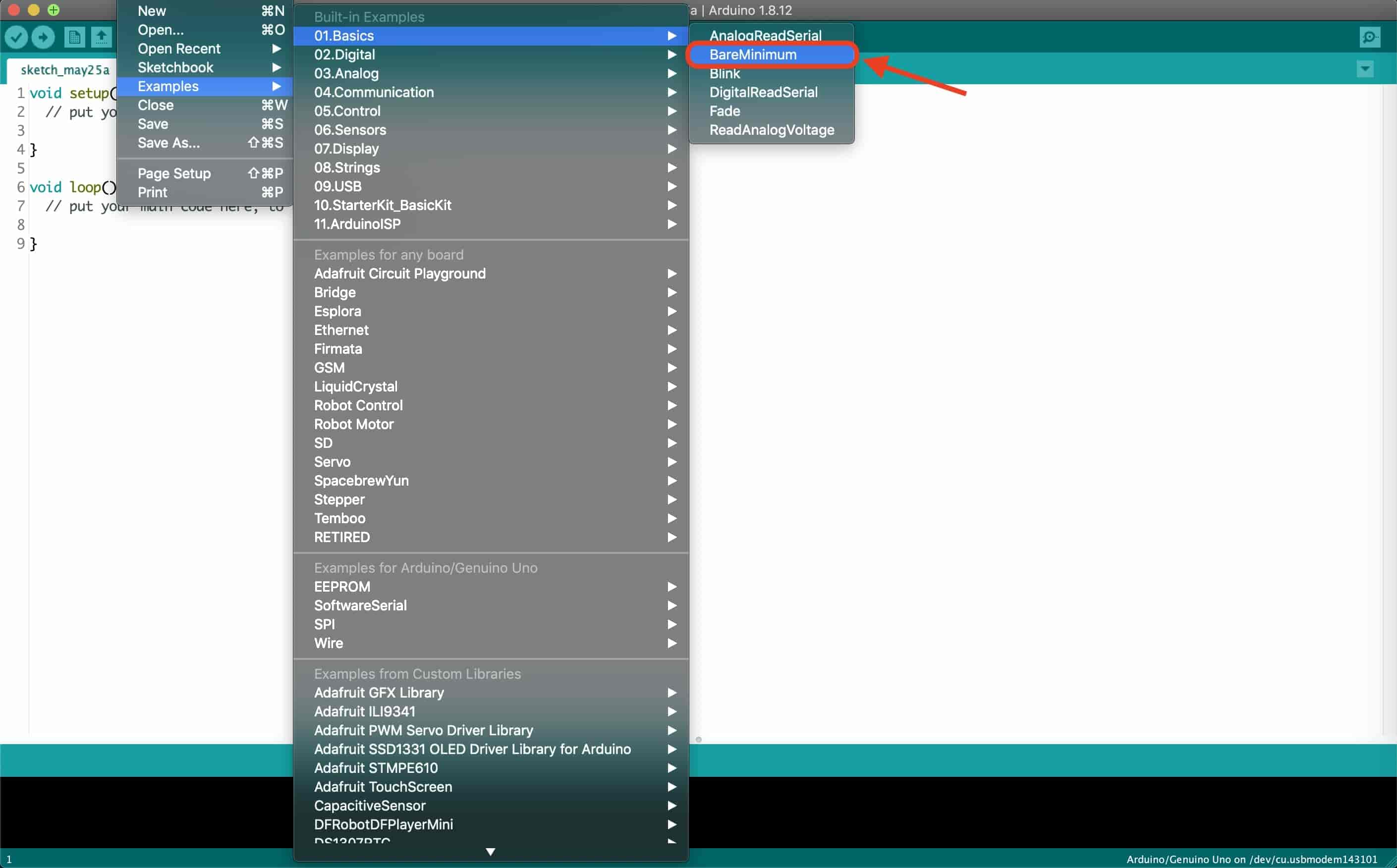
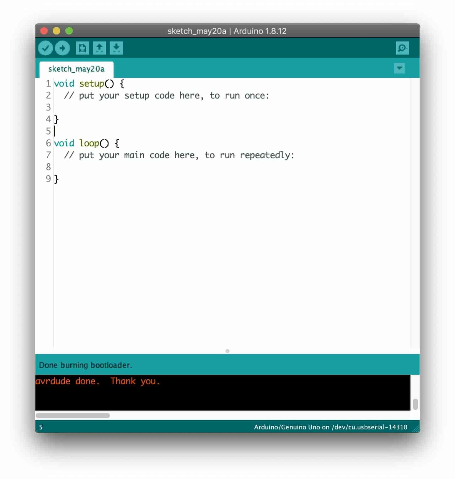
We are doing that Just to make sure that there’s nothing Executing in the background by the Arduino board.
After uploading the empty program to the Arduino board, we need to connect our ESP-01 Wifi module with the Arduino board to establish a Serial communication between the ESP-01 module and the computer to be able to send some AT commands from my Arduino IDE serial monitor to the ESP module To change the ESP baud rate(Communication speed). Here’s the wiring diagram of the circuit.
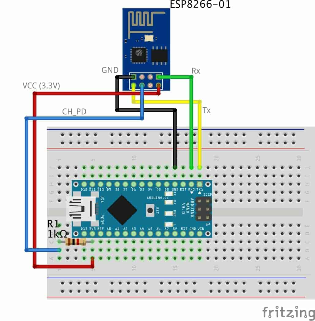
As you can see, in this step we are connecting the Tx pin(ESP-01) to the Tx pin(Arduino) and the Rx(ESP-01) to the Rx(Arduino) because we need the commands that are sent from the Arduino IDE serial monitor to get received by the ESP-01 module, not the Arduino board.
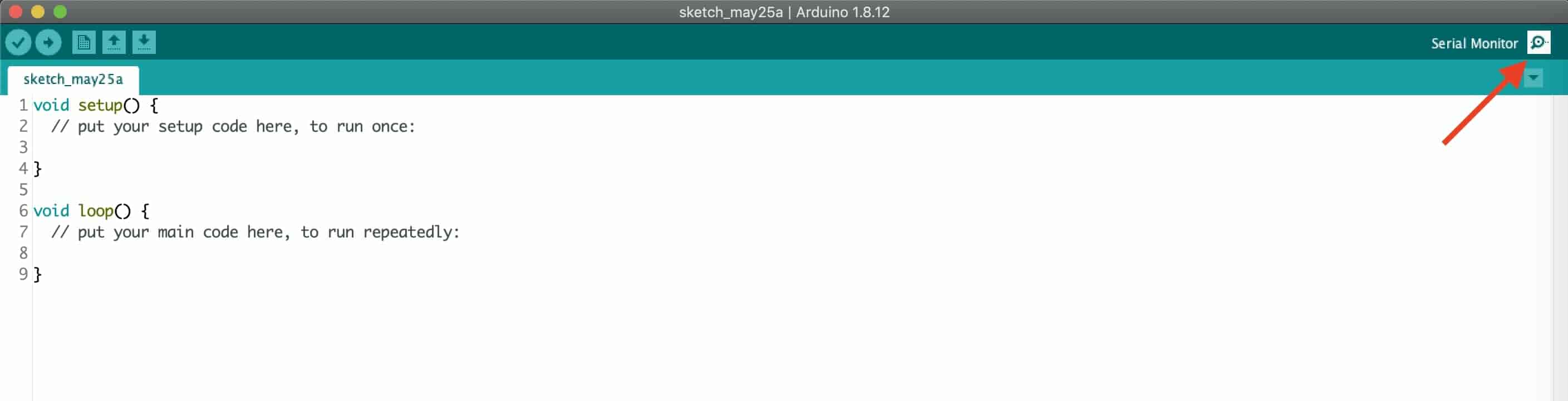
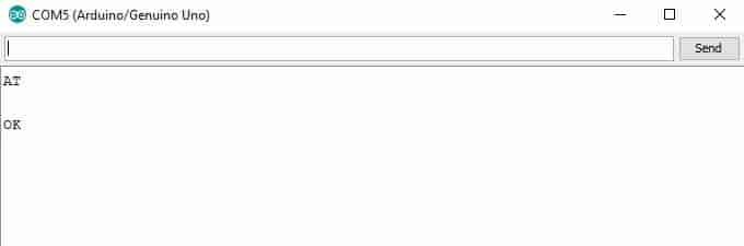
Now, connect the Arduino board with your computer using the USB cable. Open the serial monitor and set the communication speed to 115200 bit/sec. To make sure that the ESP-01 module is working and receiving the AT commands correctly, send “AT” if the module responds by “OK” that means that the ESP module is communicating and receiving the commands from the serial monitor correctly.

After making sure that the ESP is hearing you, we need to send this command AT+UART_DEF=9600,8,1,0,0 to set the baud rate to 9600 bit/sec. If this command didn’t work with you, use this one AT+CIOBAUD=9600. It depends on your firmware version. My Firmware version is 1.6 and this one AT+UART_DEF=9600,8,1,0,0 worked well for me. In some newer versions this command AT+CIOBAUD=9600 works well.
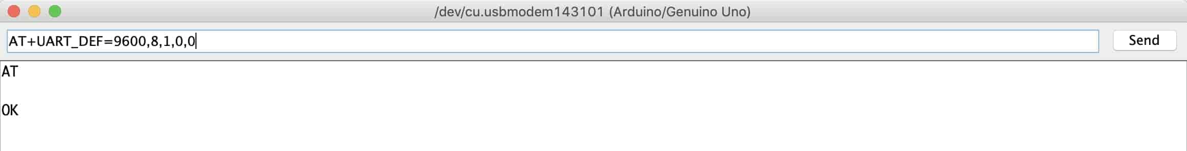
If it responds with “OK” now your ESP module communication baud rate changed from 115,200 baud to 9600 baud. CONGRATS!
Let’s change the Serial monitor communication speed back to 9600 and send “AT” again to see if the ESP module can hear us at the new Speed(9600) or not.
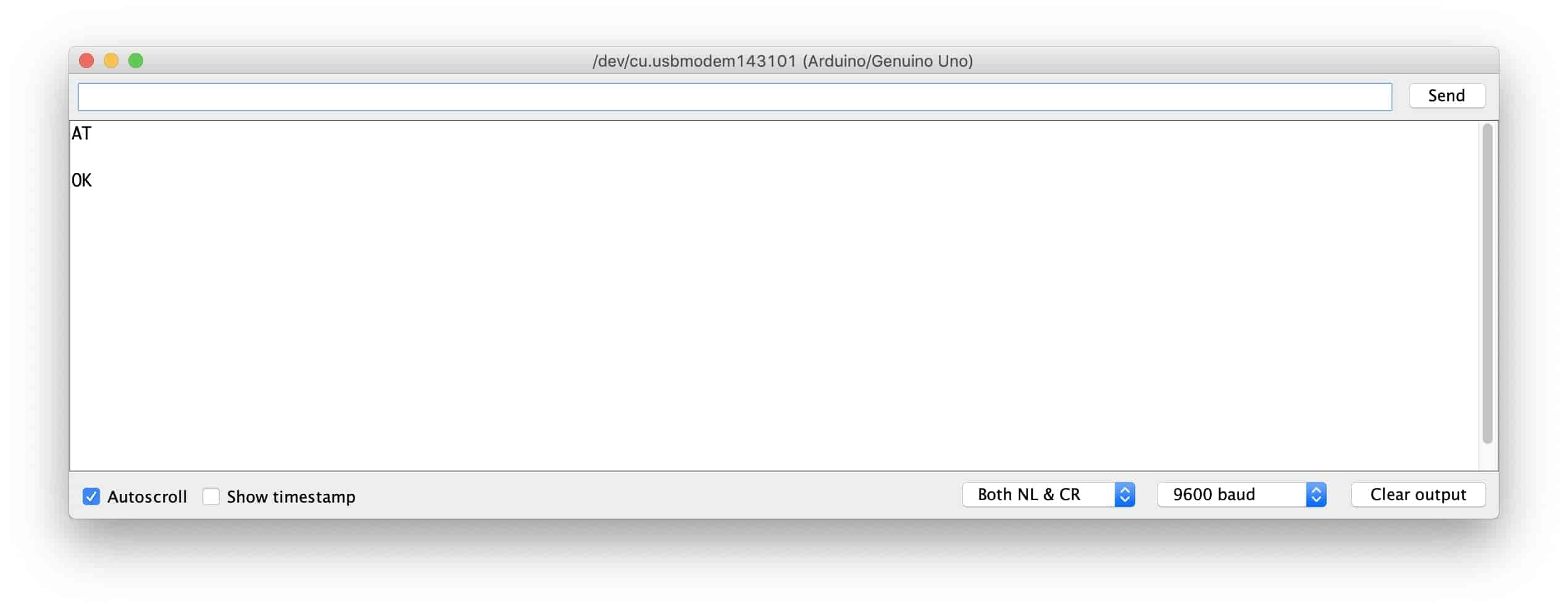
LOOK! it’s working. the ESP8266-01 now can communicate with the Arduino board at 9600 baud rate instead of 115,200 baud rate.
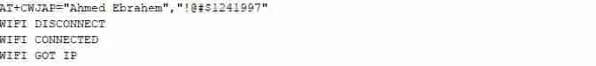
Now, let’s try to connect to the Wifi network to make sure that the ESP-01 module is working fine in the new communication speed. To connect to a new Wifi network we need to use this command AT+CWJAP=” SSID”,”Password” make sure you put your network name and password correctly and don’t forget it’s case-sensitive. You should see this message “WIFI CONNECTED” and “WIFI GOT IP” which means your ESP-01 module is connected successfully to your network and it has an IP now.
To know your ESP-01 module IP and MAC addresses we use this command AT+CIFSR.

Now, we are sure that our ESP-01 module is working properly and we can proceed while we are safe. To know more details about the different AT-commands, please check this resource out, and this one too.
Communicating With The ESP8266-01 Module Over The Internet
What’s the Internet?! Actually, the internet is a wire buried under the ground. It can be fiber optics, copper, or even a satellite but the internet is simply a wire.
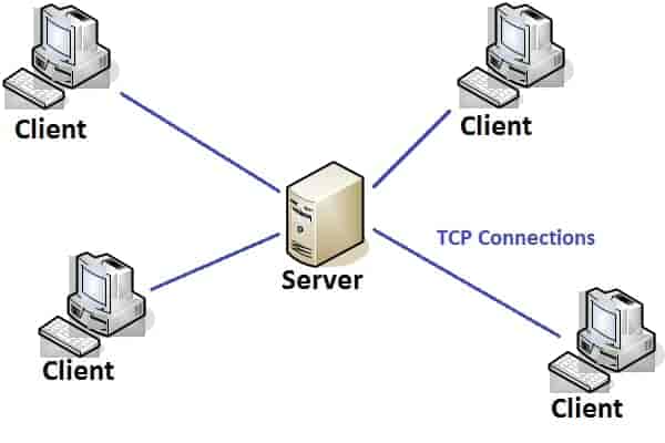
Any two computers connected to that wire can communicate. If the computer is connected directly to that wire it’s called a server and if it is not connected directly to that wire it’s called a client.
- Server: is a special computer that runs a specific Operating system like Apache, this special computer saves some web pages, files, databases on its disk drive. any server connected to the internet has a unique IP Address like 172.217.171.228, the IP address is just like a phone number helps people to find each other easily. Since that IP Address is not very easy for humans to remember. So, we just gave it a name google.com(Domain name).
- Client: it’s a computer like what you and I are using every day, it’s connected indirectly to the internet through an internet service provider(ISP) and it also has a unique IP address.
How do things work?
Simply, it starts with a request being sent from a web browser(Client) like google chrome, firefox and ends with the response received from the Web Server.
You enter the website URL makesomestuff.org in a browser from a computer(client), then this browser sends a request to the web server hosts the website, the web server then returns a response containing an HTML page or any other document format to the browser to display it.
Exactly, that’s what we need to do today in our project. We need to send a request from the web browser(Client) to the ESP8266-01(Web Server) which both of them are connected to the same local network(Wifi). This request contains some data which tells the ATmega Server board what to do like turning on or off an LED. After that, we will replace the web browser with another ESP-01 board that is working as a client to send the sensor data to the Server board.
Building the Web Page
To build our web page we have to deal with HTML, CSS, Javascript. if you never heard about these names before, don’t worry I got you.
HTML: Stands for “HyperText markup language” we use it to build any web page main structure. Like adding some buttons, images, paragraphs, headers, tables, and many more elements. it consists of a series of elements that tell the browser how to display the web page content. These elements are represented by something called tags.
CSS: It stands for cascading style sheet. After building the web page main structure, you need to make this structure look nice. Here comes CSS to make some styling. it’s a language that describes the style of an HTML element. it consists of some selectors and deceleration blocks.
Javascript: it’s a programming language that we will use to make the web page more interactive like adding some animations, maps and it allows us to make some complex things on the web page. Mainly, we will use it today to send an HTTP request from the client(web browser) to the Web Server(ESP8266-01) to take some actions like turning on or off a light bulb. Or a motor or anything.
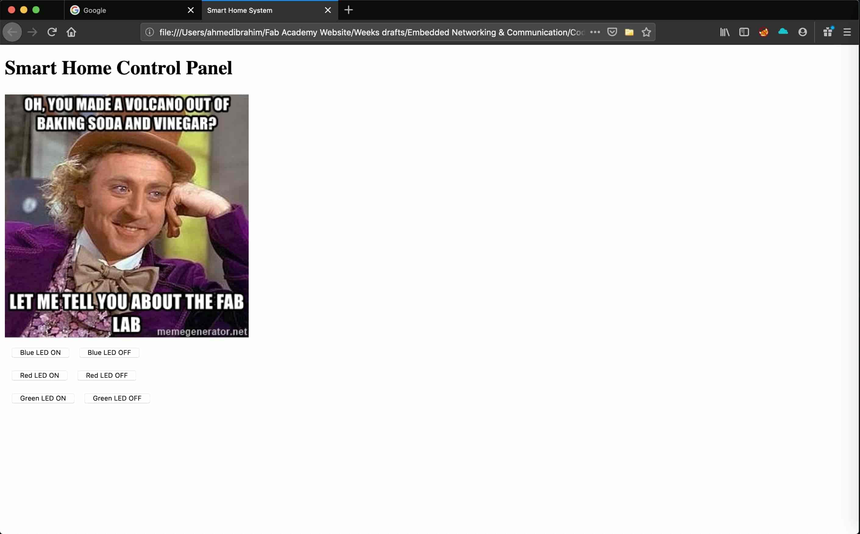
As we see our control panel is very simple, it contains one header, one image, and Six buttons for controlling three LEDs. Turning them on or off.
- <!DOCTYPE html>: declaration defines that this document is an HTML5 document.
- <html>: the root element of an HTML page.
- <head>: contains meta-information about the page.
- <title>: specifies the title of the document. this title appears on the web page browser tab.
- <body>: contains the visible web page content.
- <h1>: defines a large header element.
- <img>: adds an image to the web page. the image that you want to display should be in the same project folder.
- <br>: advance the cursor to a new line.
- <button>: adds a button to the page content.
Each button on our web page has very important two attributes: the id, and the class attributes. we will talk about why we assigned these two values to the buttons in the Jquery code explanation part.
The web page that we built using HTML does not look very cool. We need to add some colors, set the alignments of the page elements, and adjust the sizing of the page elements.
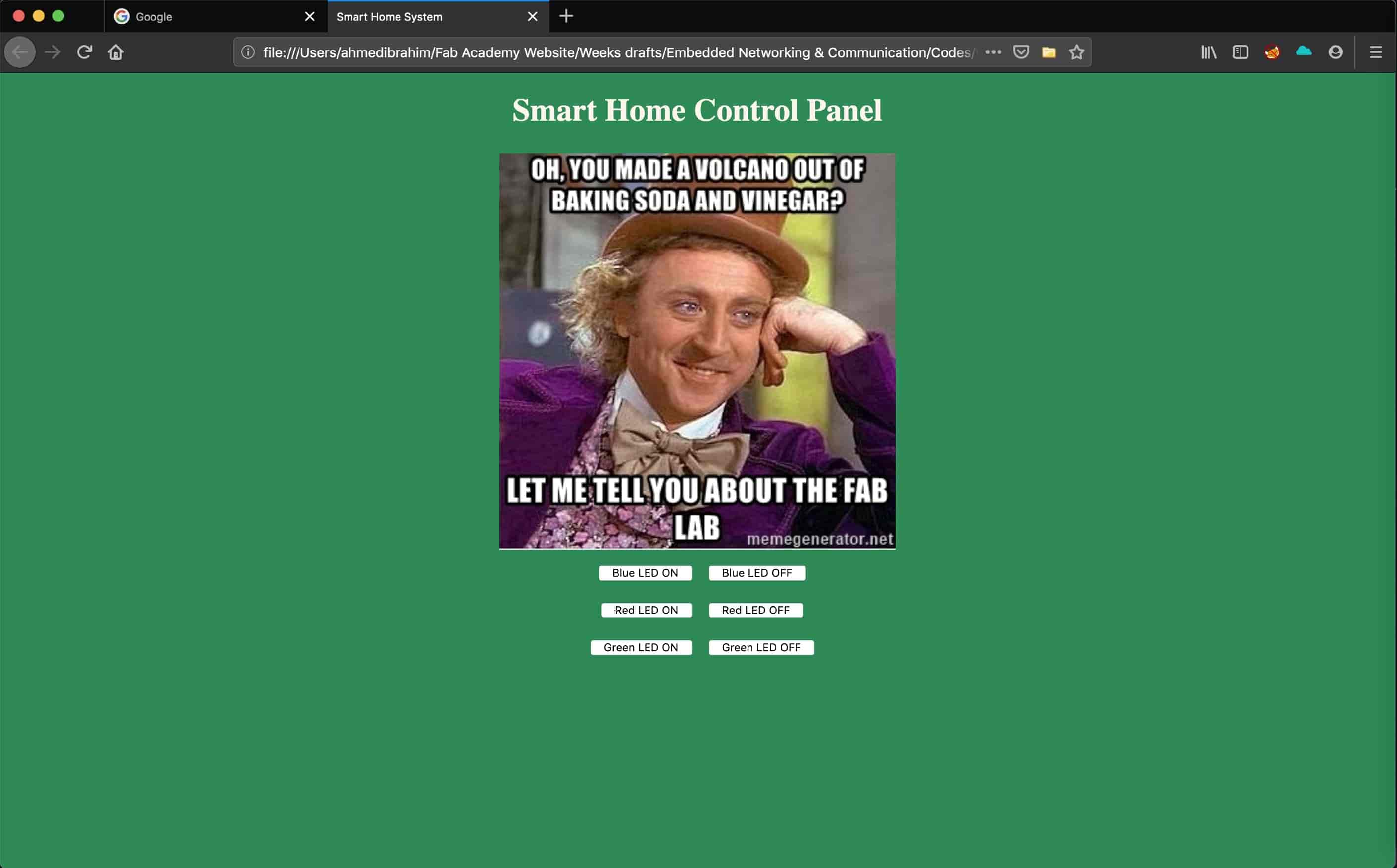
Now, the web page looks cooler (NOT TOO MUCH xD) we gave it a cool green background color, we make the page content centered aligned, and we change the headers font color and font family which made the web page more alive. We used CSS to do all of this styling stuff.
We added style="background-color: seagreen; color: seashell; text-align: center;" inside the body tag to make all the web page content in the center of the page and to set the background color to seagreen also to set the font color to seashell. Also, we added style="margin: 10px;" inside the two button tags to set a margin of 10 pixels around the four sides of each button.
Now, after building our web page structure and styling it we need to add some functionality to the buttons which we added earlier in the web page. It’s the time for the communication part, we need to find a way to send an HTTP request to the ESP-01 server board when we click on any button in the web page that we have built. After doing some search I found that the Jquery has a built-in function called .get() that sends a specific data to a specific IP address. That's what we need dude! This unique data tells the ESP8266-01 server board to turn on or off the LED.
First Things First, we need to import the Jquery library in our code. So, we added this line in the head tag.
<script src="https://ajax.googleapis.com/ajax/libs/jquery/3.3.1/jquery.min.js"></script>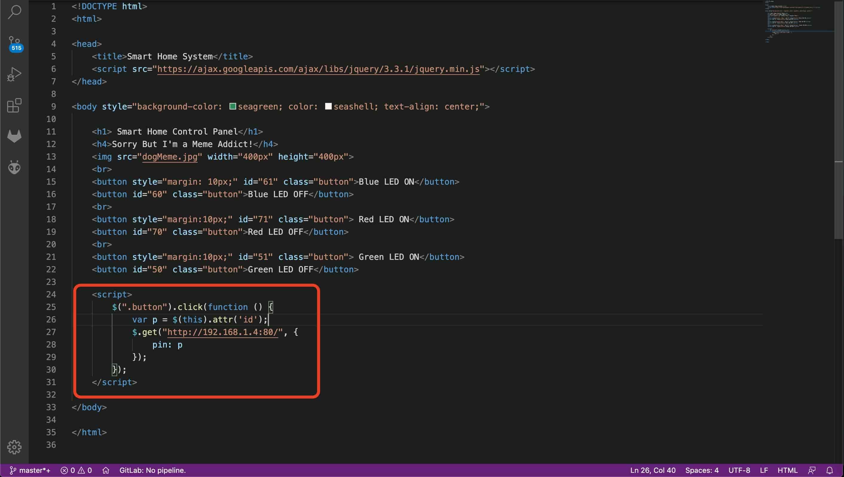
In this part, all the magic happens.
- $(".button").click(function () {
When the user clicks on any button associated with the class “button”, trigger the following function.
- var p = $(this).attr('id');
Get the value of the clicked button attribute “id” and store it inside the “p” variable.
- pin: p
Put the variable “p” value in a dictionary (key-value pair) . Its key is “pin” and the value is “p” variable value.
- $.get("http://172.20.10.11:80/", { pin: p });});
Then, send a GET request to the server board whose IP address is “172.20.10.11” on port 80. this GET request contains the value of the attribute id of the pressed button.
In case the user pressed the “Blue LED On” button, the id variable value will be 61, so the GET request header will contain some data like this pin=61. look at the next figure!
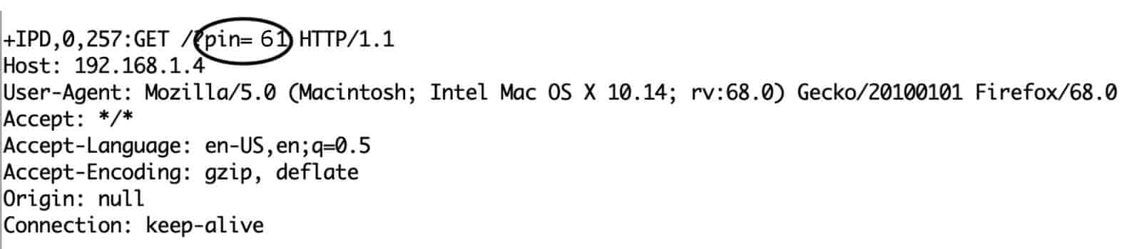
But, what does this number mean? Ok, Lemme answer you fam. Actually, the number 61 and 60 is divided into two parts.
- Part one: is the first number which is “6” (in case we pressed “Blue LED On which id is 61”), it refers to the ATmega pin number which the load I need to control is connected on.
- Part two: is the second number which changes between 1 and 0 depending on the clicked button. And it refers to the pin state(ON or OFF).
In the C code, we will receive this data and separate these two parts from each other and save each part in a different variable, part one in variable pinNumber and the second part in variable pinState, then we will write this simple line of code to control the connected load
digitalWrite(pinNumber, pinState);Wiring things up
After we finished building the web page, we need to connect the ESP8266-01 module and an LED with the Arduino nano board to test our code logic and the electronic circuit on a breadboard before designing it on Eagle. Here’s the wiring diagram
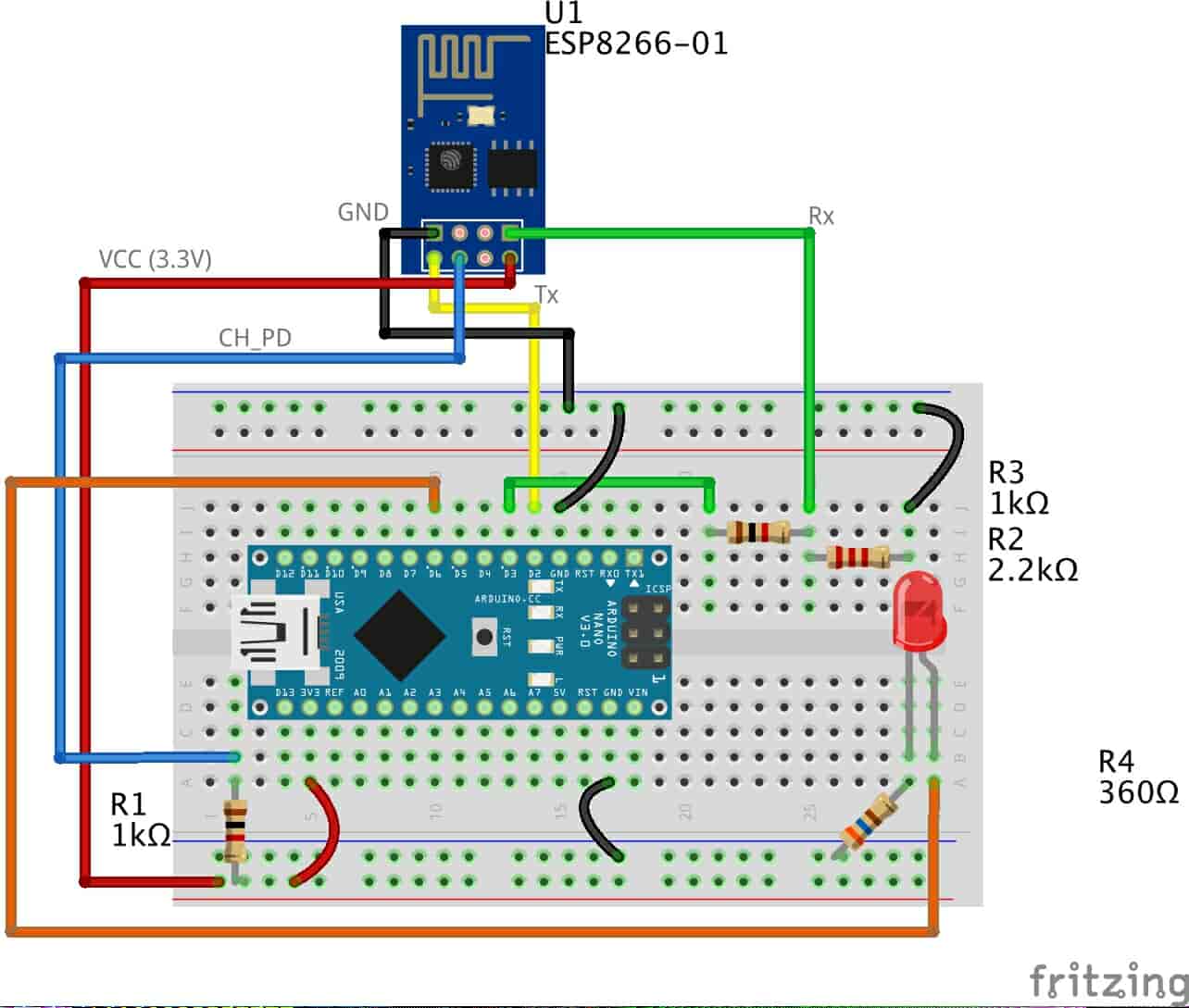
The wiring is pretty straightforward, the ESP-01 Serial communication pins are connected to the Arduino Nano digital pins 2, 3(Software Serial Tx, Rx) to allow the two devices to share data with each other. And a very normal LED is connected to the Arduino Digital pin 6.
Arduino Programming
the code is pretty straightforward, we implemented two different functions InitWifiModule() and sendData()
the sendData() function job is regulating how the AT commands will get sent to the ESP8266-01 module over the Serial communication.
The InitWifiModule() function job is to provide the sendData() function the AT commands that we need to send to the ESP8266-01.
in the loop() function we read the coming HTTP request header and search for the “+IPD,” which means that the request has successfully arrived, then we read the pin value which it will be “61” if the user clicked the “Blue LED ON” button and “60” if the user clicked “Blue LED OFF” button.
don’t forget to put your wifi SSID and Password in the Arduino code line no. 103
sendData("AT+CWJAP=\"PUT YOUR SSID\",\"PUT YOUR PASSWORD\"\r\n", 2000, DEBUG); //connect to the WiFi network.for more code explanation please read the comments in the code, it’s well documented(I hope)
Note that, we will use the same code with the new PCB that we will design in the next step.
Designing the Client & Server PCBs
Since we are sure that everything is working just fine on the breadboard, that’s the time to convert the breadboard circuit to an actual PCB. I’m using the awesome Eagle software from Autodesk to design my PCBs.
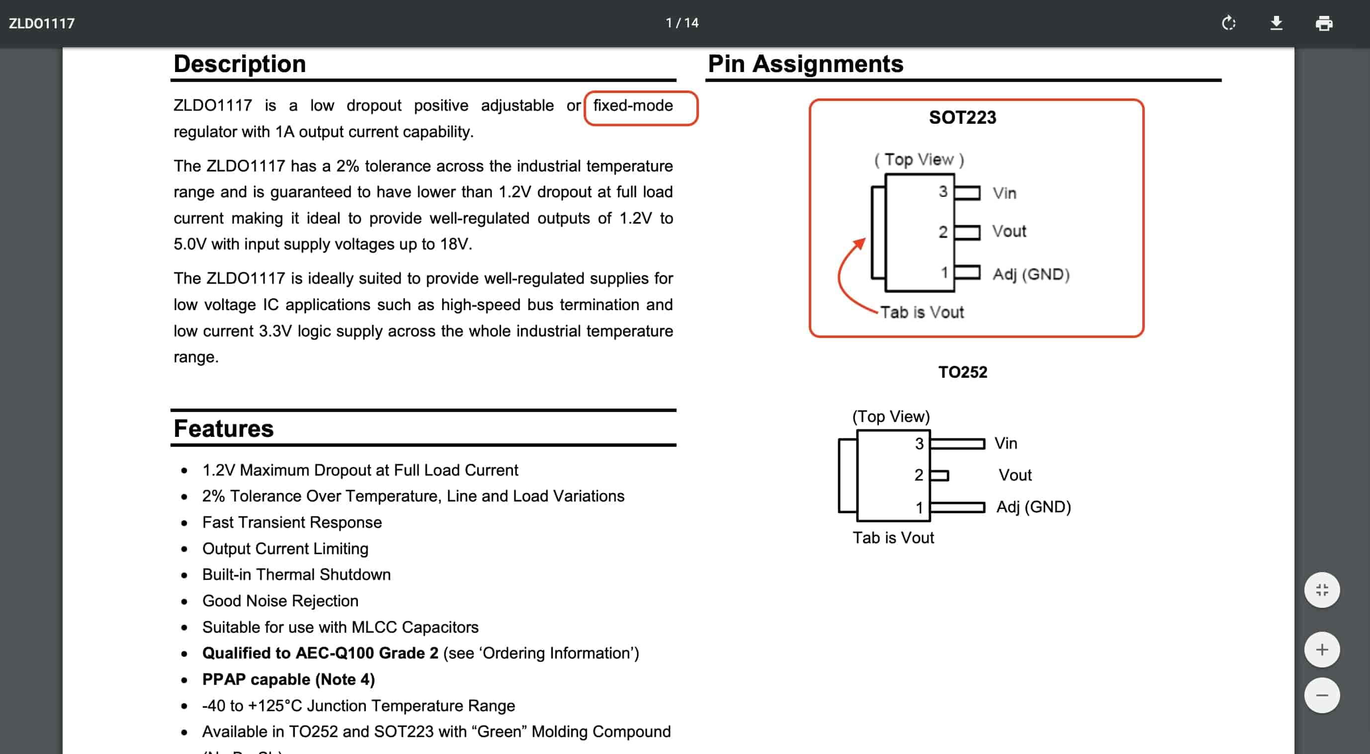
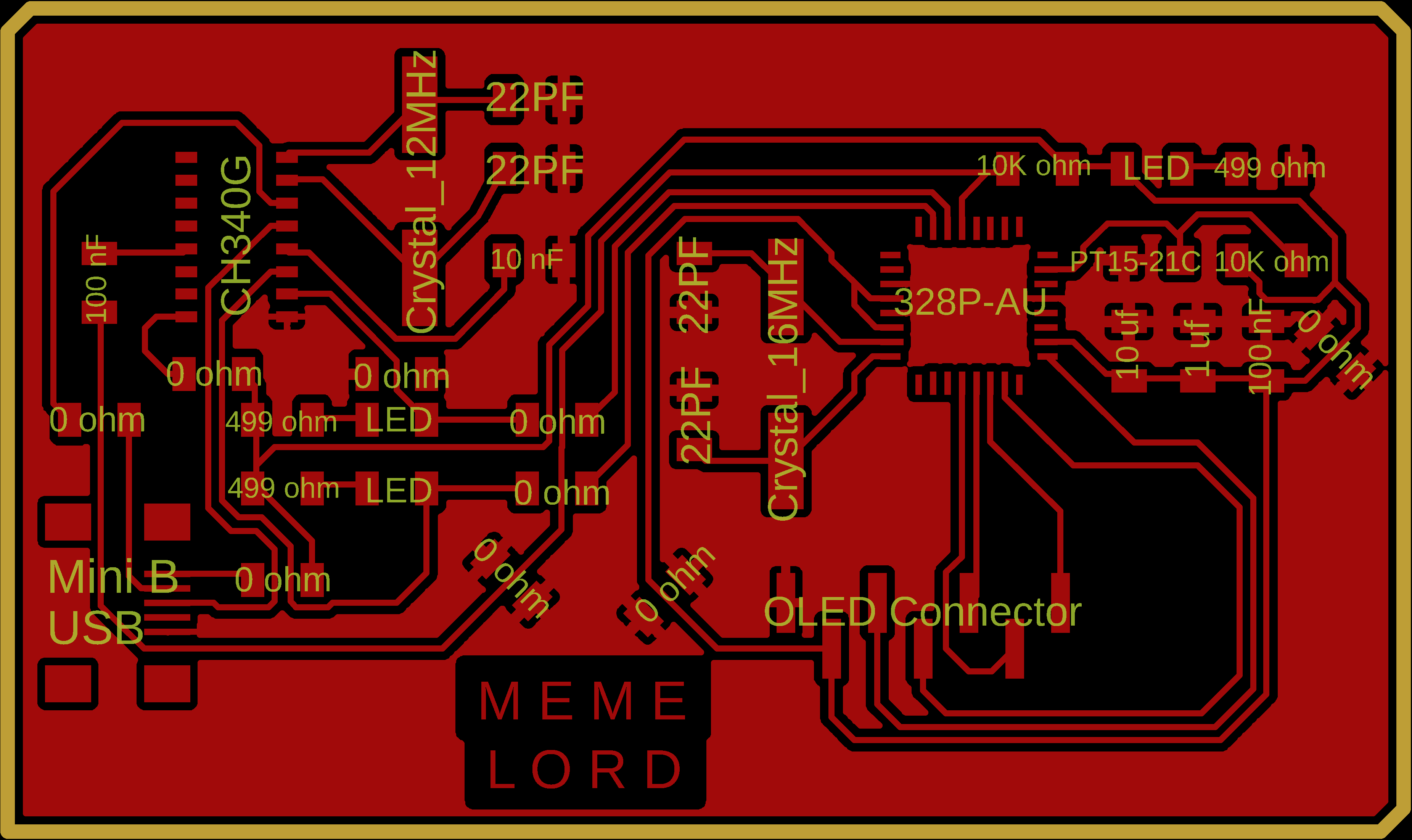
Both of the Client/Server PCBs are based on the Atmega328P-AU microcontroller along with 16MHz crystal oscillator, 3.3V Voltage regulator that can handle upto 1 Ampere to supply the ESP-01 with the 3.3V power needed without ruining the module or the microcontroller, and an RGB LED to give us some feedback what’s going on.
The Client board also has an NTC temperature sensor that will tell us the temperature value which we will send later to the Server board to display it on the OLED screen.
The Server board has a 7-pins pin header connector to easily mount the OLED screen on it.
As we stated before, We are using a 3.3V voltage regulator that can supplu upto 1 Ampere.
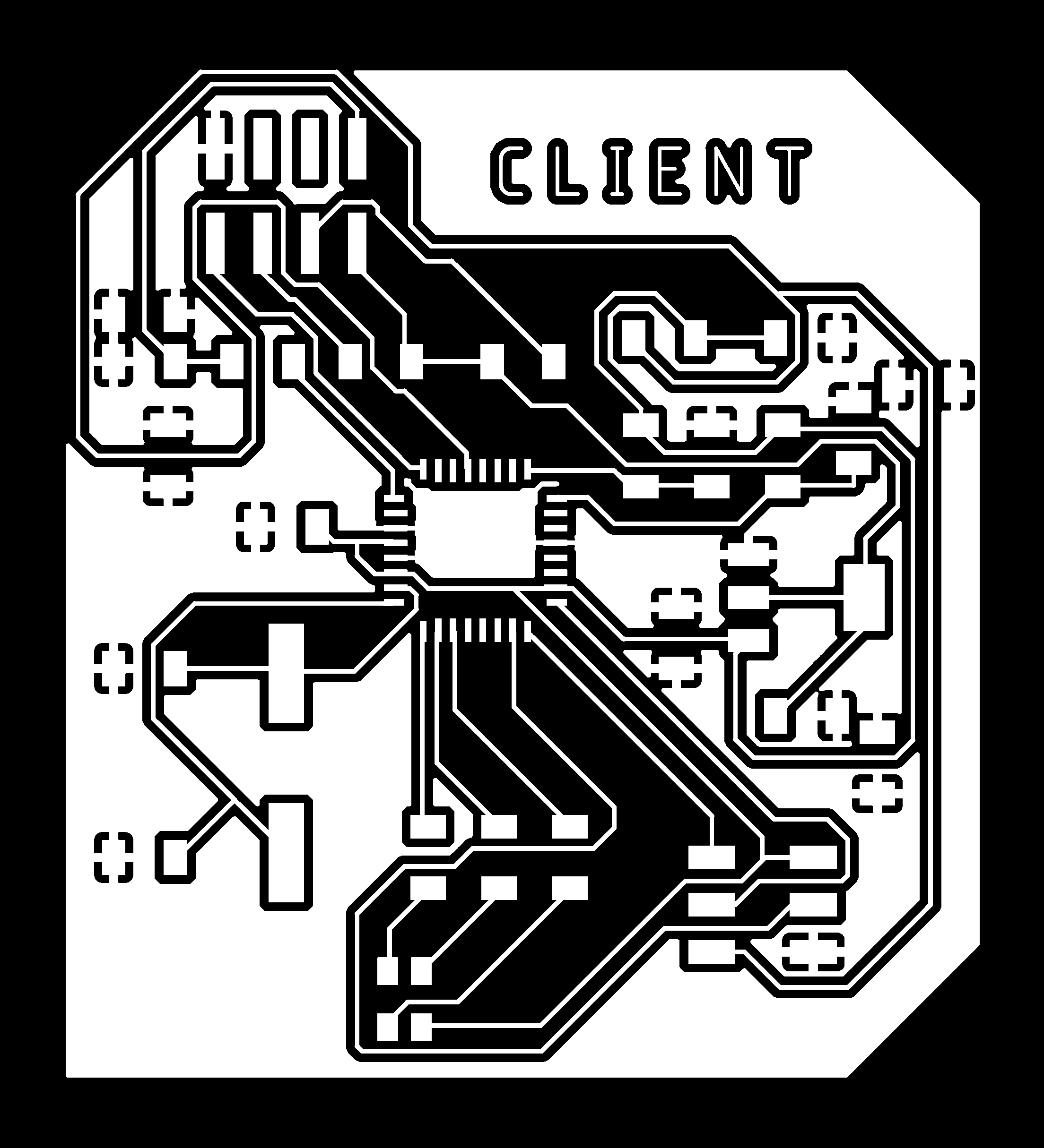
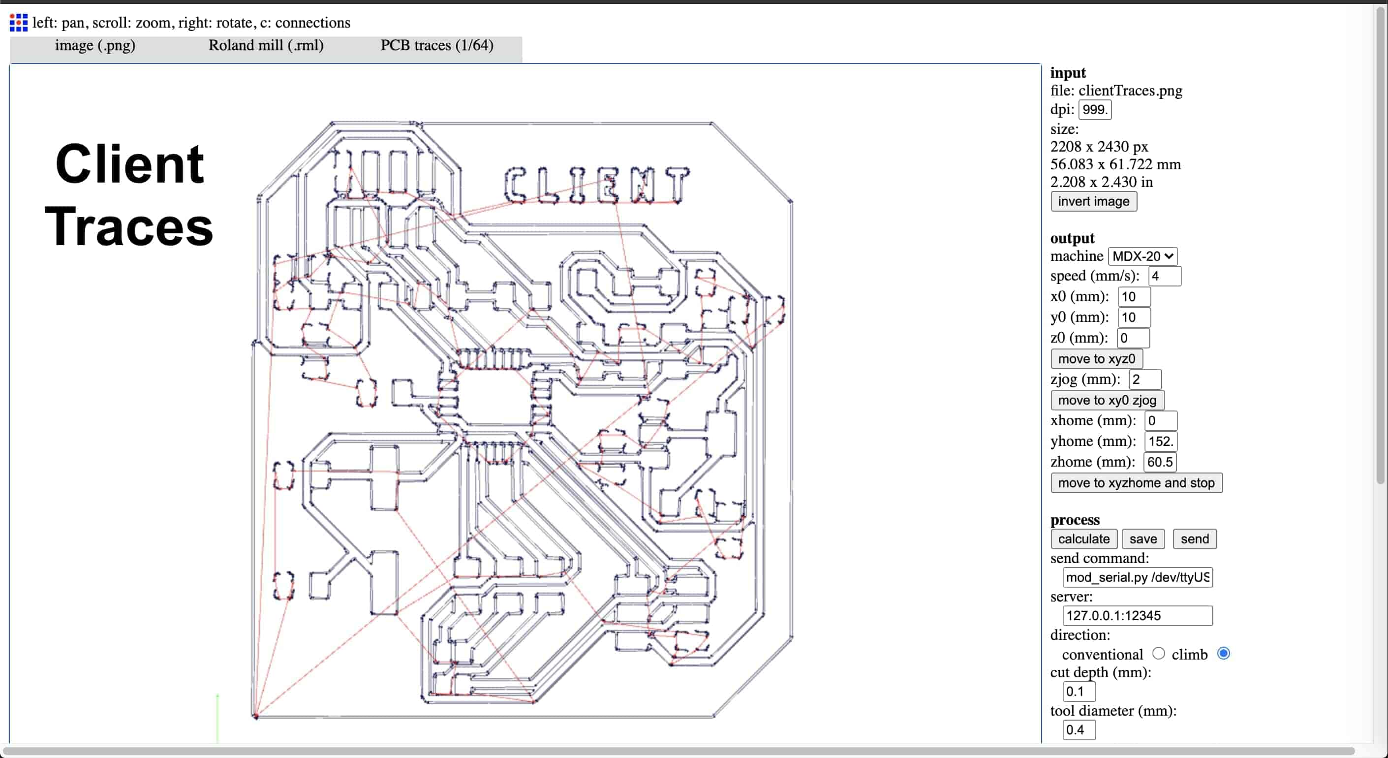
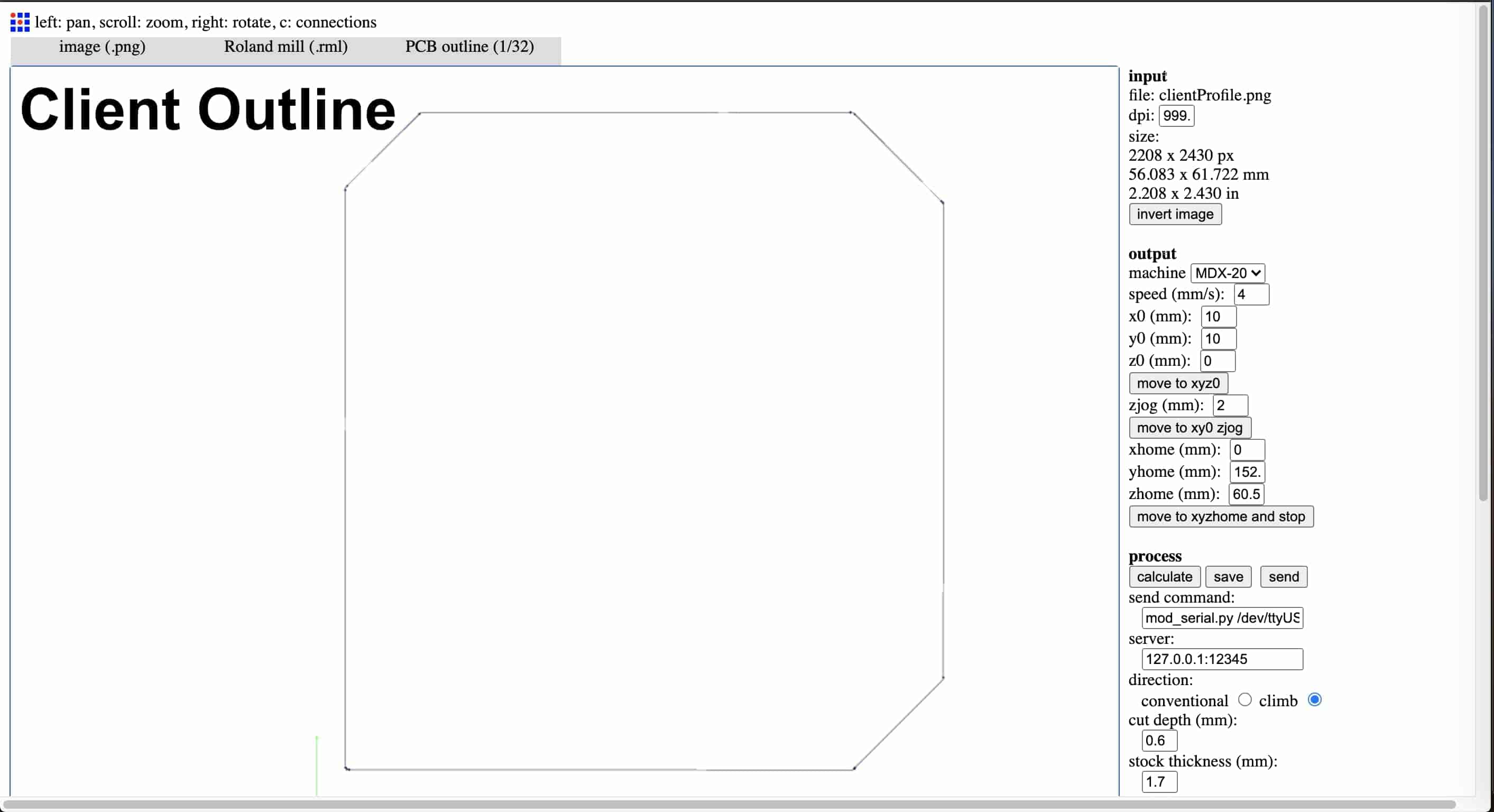
Client PCB PNG Files Download
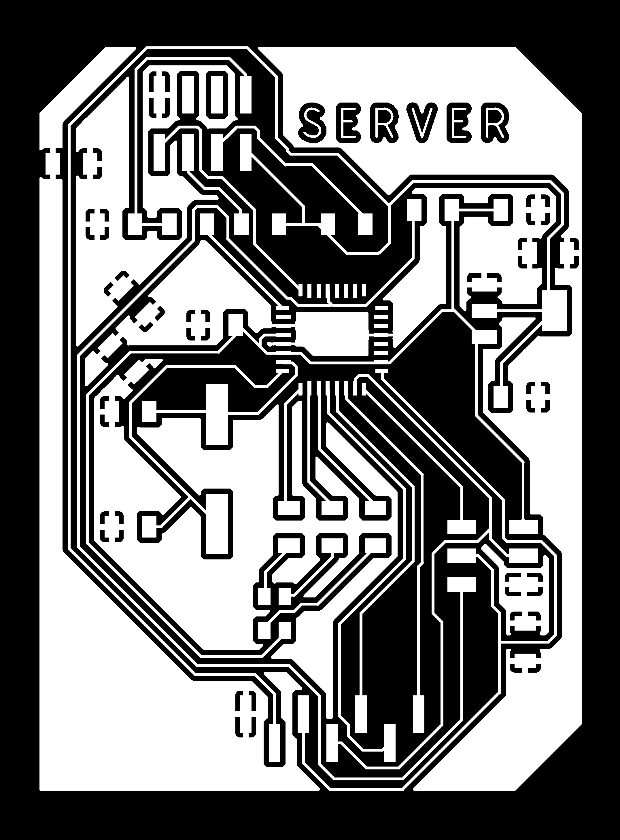
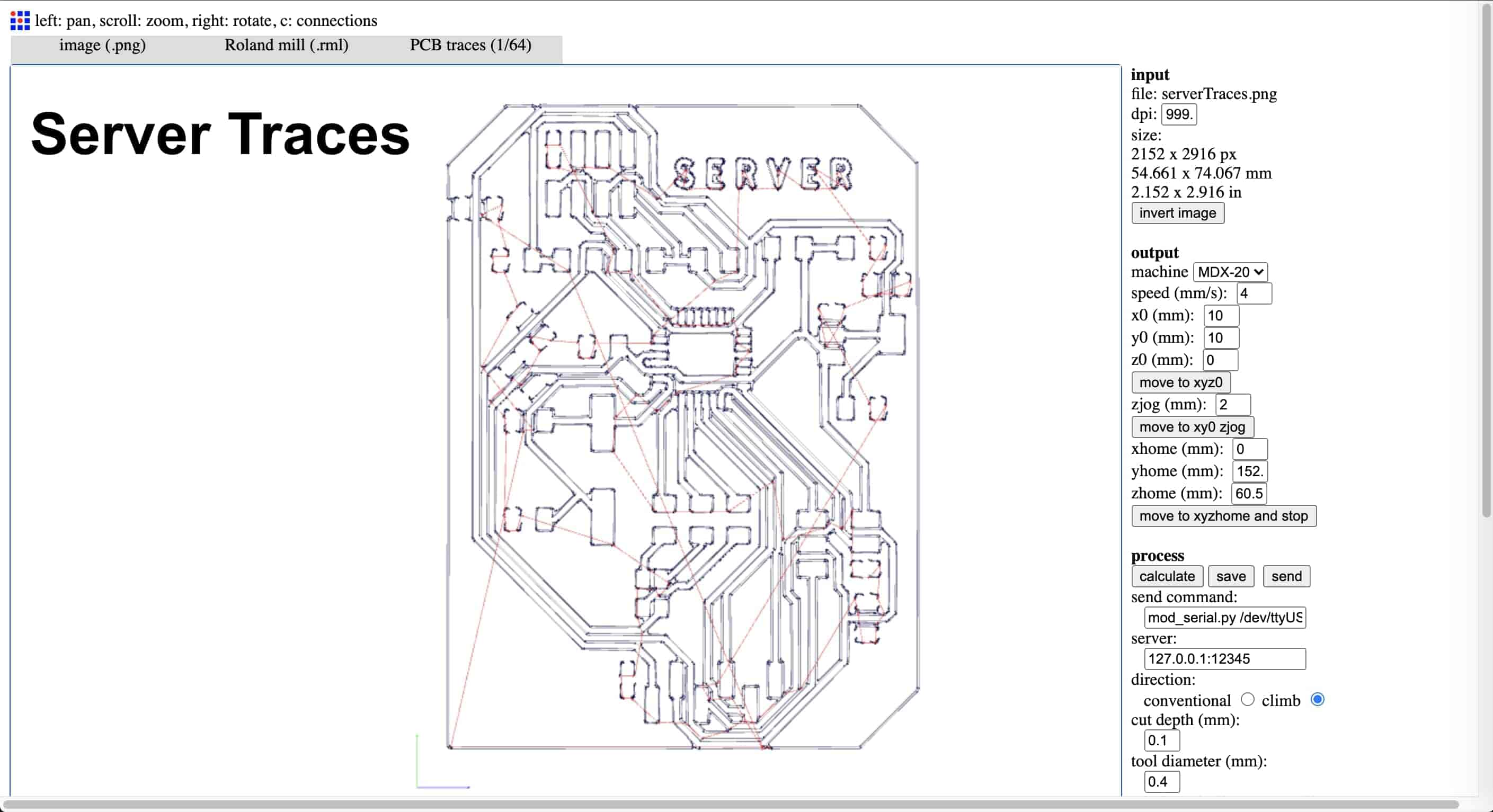
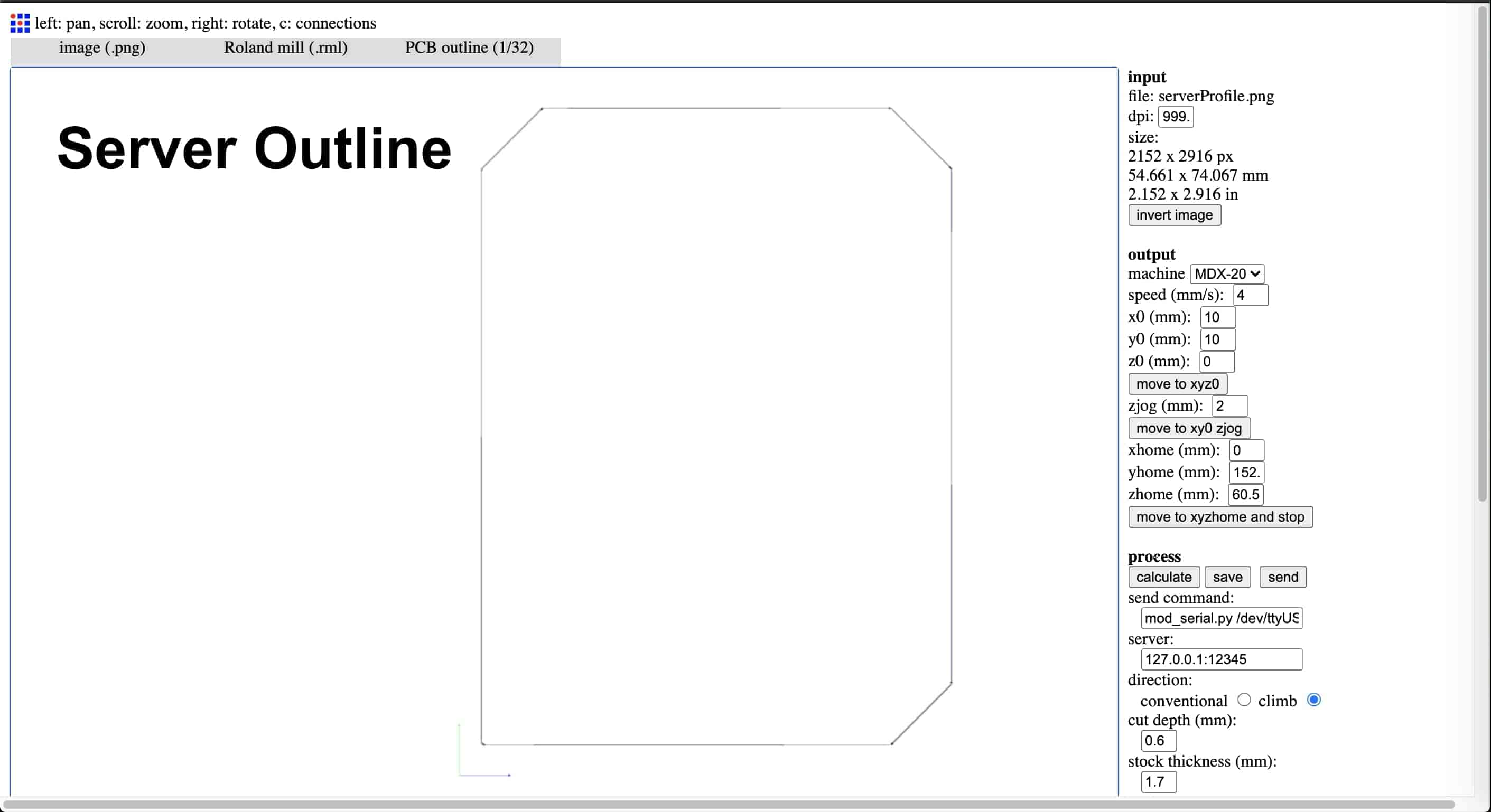
Server PCB PNG Files Download
PCB Fabrication and Soldering
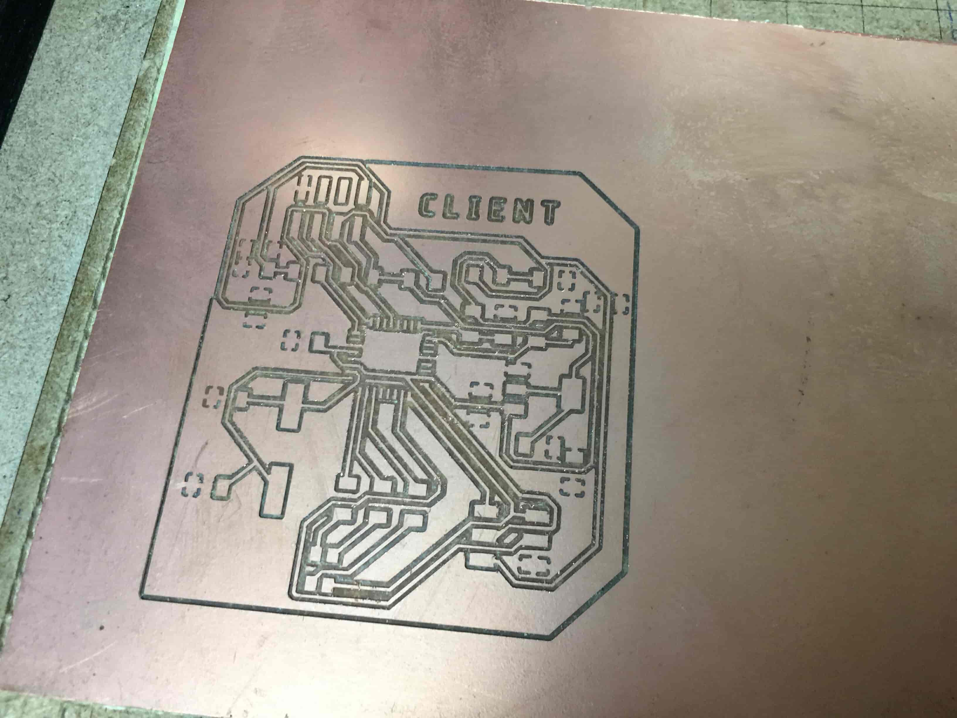
After finishing the PCB designing, it’s the time to fabricate our board. In Fablab Egypt We are using the Roland MDX-20 machine and the Fab Modules as a CAM software.
I Imported the Top Traces PNG Image to the Fab Modules and set the parameters and the origin point according to my job. I’m using a 0.4mm bit to make the Traces so I set the tool diameter to 0.4. After finishing the traces, I imported the outline PNG image and set the tool diameter to 0.8mm both at speed 4.
If you are curious and wanna know more details about the PCB Fabrication check out the Electronics Production week assignment.
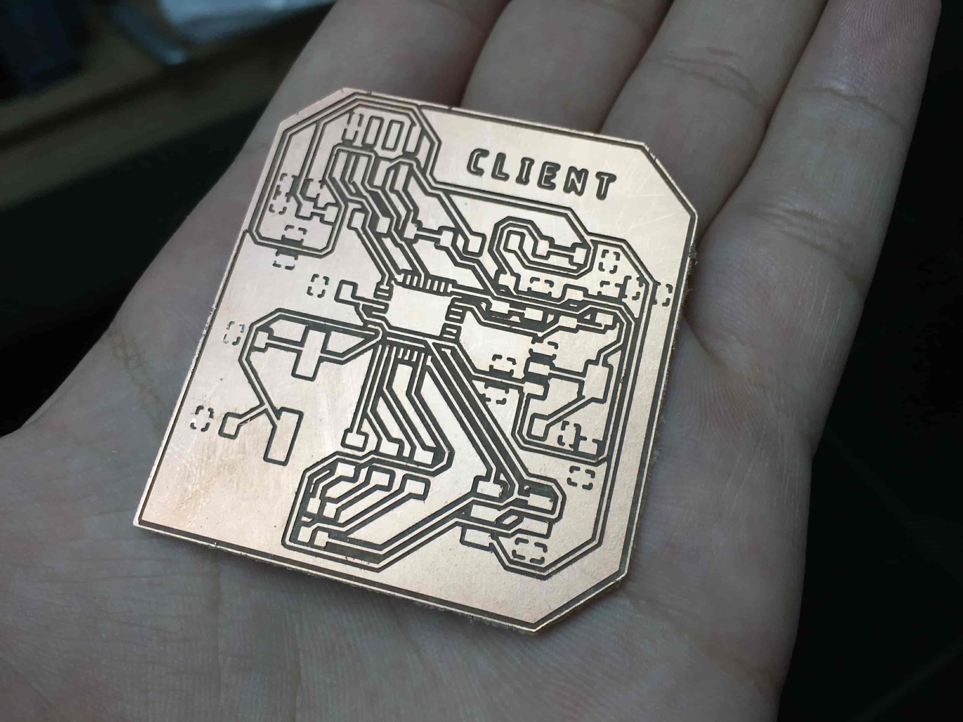
And here's the PCB after getting fabricated at the Modela.
Here's the components needed for both the Client and Server PCBs.
| Part Number | Description | Quantity | Supplier |
|---|---|---|---|
| ATMEGA328P-AU-ND | IC MCU 8BIT 32KB FLASH 32TQFP | 2 | digikey |
| 2395958 | 16Mhz/18pF SMD 11.4 x 4.7 mm crystal | 2 | Farnell |
| 445-1423-1-ND | CAP CER 1UF 50V X7R 10% 1206- | 2 | digikey |
| 587-1352-1-ND | CAP CER 10UF 35V Y5V 1206- | 4 | digikey |
| 2984995 | SMD Multilayer Ceramic Capacitor, 22 pF, 10 V, 1206 | 4 | Farnell |
| 311-10.0KFRCT-ND | RES 10.0K OHM 1-4W 1% 1206 SMD | 10 | digikey |
| 311-499FRCT-ND | RES 499 OHM 1-4W 1% 1206 SMD- | 9 | digikey |
| 311-0.0ERCT-ND | RES 0 OHM 1-4W 1% 1206 SMD | 10 | digikey |
| 235-1109-1-ND | THERMISTOR NTC 10K OHM 10% 1206- | 1 | digikey |
| SSD1331 Color OLED Screen 0.95inch | Color OLED Screen 0.95' | 1 | Ali Baba |
| CLV1A-FKB-CK1VW1DE1BB7C3C3CT-ND | LED RGB 4PLCC SMD | 2 | digikey |
| 609-5161-1-ND | 6 Positions Header Connector 0.100" SMD | 2 | digikey |
| S5674-ND | CONN FEMALE 8POS DL .1" TIN SMD | 2 | digikey |
| ZLDO1117G33DICT | IC REG LDO 3.3V 1A SOT223-3 | 2 | digikey |
| ESP-01 | ESP8266-01 Wifi Module | 2 | AliBaba |
After getting the components from the inventory and soldering the two PCBs it’s the time to test them.
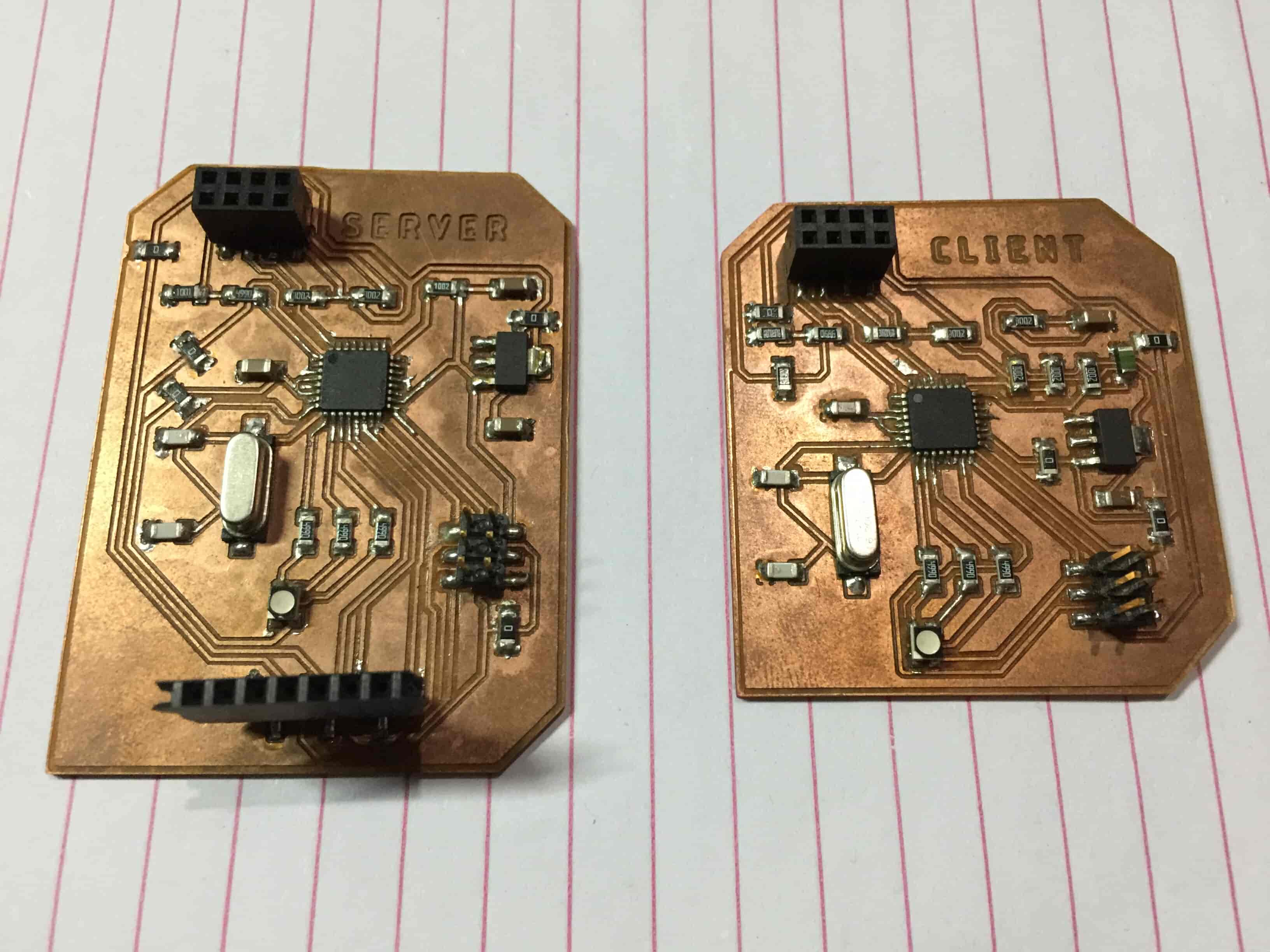
Don't forget that there’s an RGB LED on both the server and client PCBs. Each color of the RGB LED is connected to a different digital pin on the microcontroller. The red LED is connected to digital pin 7, green LED is connected to digital pin 5, and the blue LED is connected to the digital pin 6.
PCBs are talking to each other!
So, each button on the web page that we built before will send a specific number according to the button that the user pressed. If I pressed the “Blue LED ON” button it will send the number “61”. The first digit refers to the pin number, and the second digit refers to the pin state. And the same concept applied to the other buttons.
Now, let’s replace the web page with the client PCB that we designed. We need the client PCB to send some data to the Server PCB over the internet. Let’s begin small. Let’s try to send also the number “61” to the Server PCB and see if the two boards are communicating
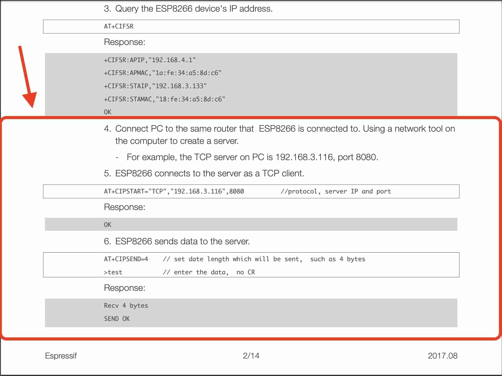
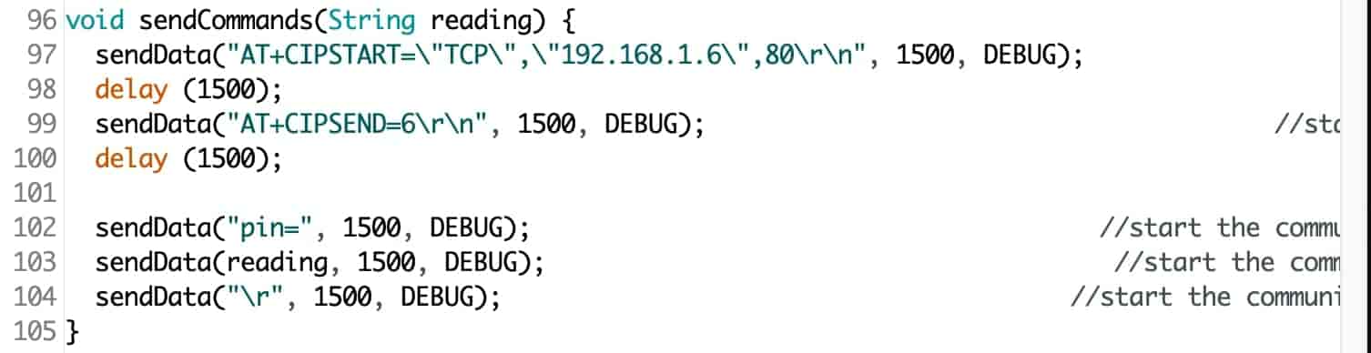
Let’s write the program that will run on the Client PCB. The login behind the code is pretty simple. First, to connect to the server board as a TCP Client we need to know the server IP address and the port number that we will communicate through. We will communicate over port 80(HTTP) and my Server board IP address is 192.168.1.6. Your board IP address will be different from mine for sure it depends on your router and your network. So, to know your board IP address, go to your router admin page and get your device IP number.
Another note, both of the Client and the Server boards should be connected to the same network(router) because we are establishing a local network connection that your home router is routing the data from one device to another(from client board to server board).
Then we need to specify the length of the data that we will send to the Server board. Each character in the string will take one byte. So, in total i’m sending 6 bytes to the Server board. Checkout this PDF for more information.
The Server board program is pretty straightforward too, after reading the incoming data from the Client board, we check the incoming data using if conditions and according to that data it takes different actions.
with each other or not. If the two boards are talking to each other correctly, the blue LED on the Server board should light up.
Yaaaay! They are talking to each other. Now, instead of sending hardcoded data, we need to read the temperature sensor value from the Client board and send it to the Server board to display that value on the OLED screen and change the RGB LED color according to the sensor readings.
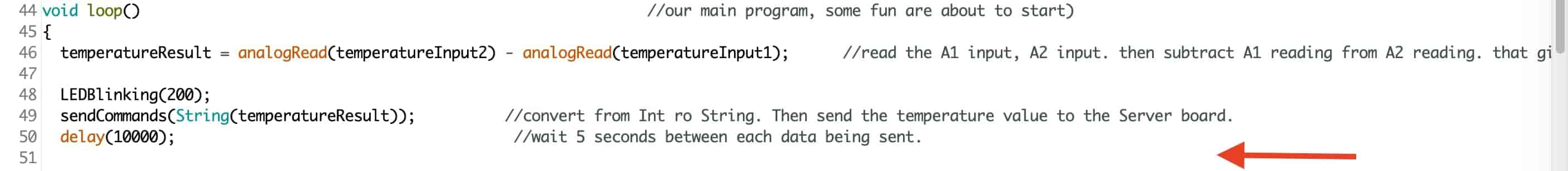
In order to achieve this, we need to make some small modifications in the Client and Server boards programs. In the Client program, we will read the Thermistor values which is connected on the analog pin A1, A2(We are using a Wheatstone Bridge) then we subtract the two values from each other to get the actual thermistor temperature voltage. You should use some sort of equation to convert from voltage to the actual temperature, but I will just use the result voltage for now just to prove the concept. After getting the result thermistor voltage we will convert this value from integer to string and send it to the Server board.

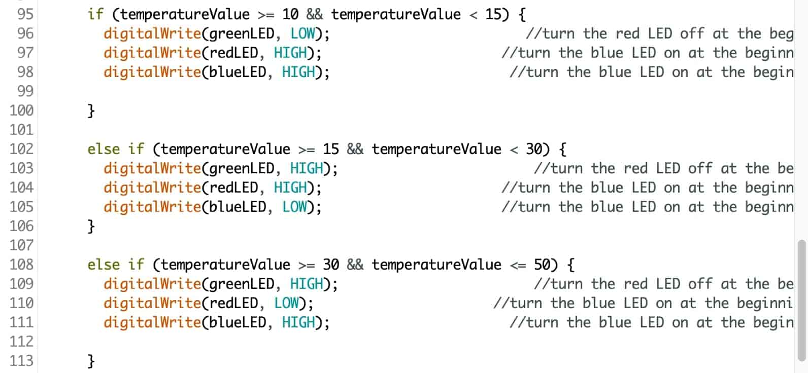
In the Server board program, we read the incoming values each digit separately then add them together,
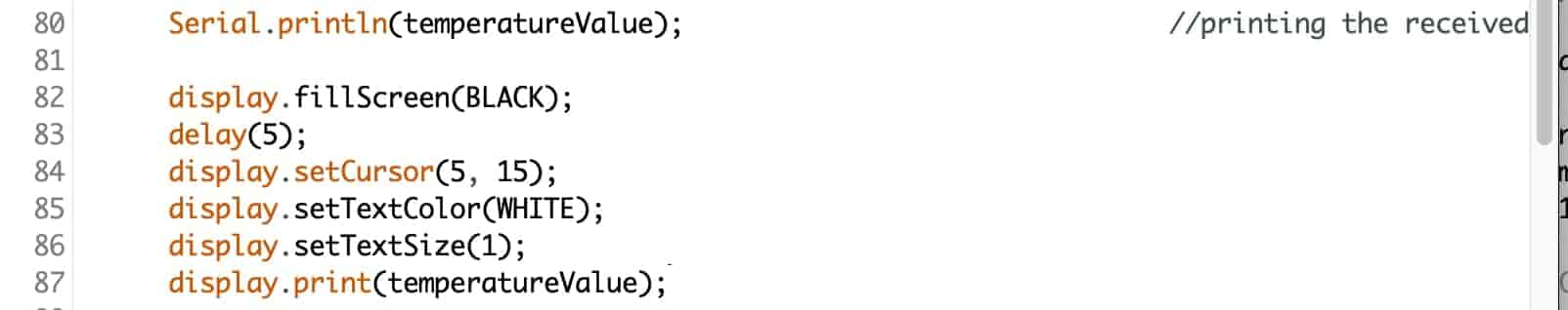
Then we print the temperature on the Serial monitor just for debugging purposes, and display it on the OLED screen
Then if the temperature value is between 10-15 the green LED will turn on, between 15-30 the blue LED will turn on, between 30-50 the red LED will turn on.
After writing the programs and uploading it to the boards. Let’s test that thing! We should see the sensor reading on the OLED screen and the RGB LED should change its color according to the sensor value.
Some Useful Resource
- http://fab.cba.mit.edu/classes/865.15/people/dan.chen/esp8266/
- https://makesomestuff.org/iot-using-esp8266-01-and-arduino/
- http://www.microchip.ua/wireless/esp01.pdf
- http://eleceng.dit.ie/gavin/Instrument/Signal%20Cond/WB1.html
- http://fab.cba.mit.edu/classes/863.18/CBA/people/mani/week-8.html
- https://www.instructables.com/id/Getting-Started-With-the-ESP8266-ESP-01/