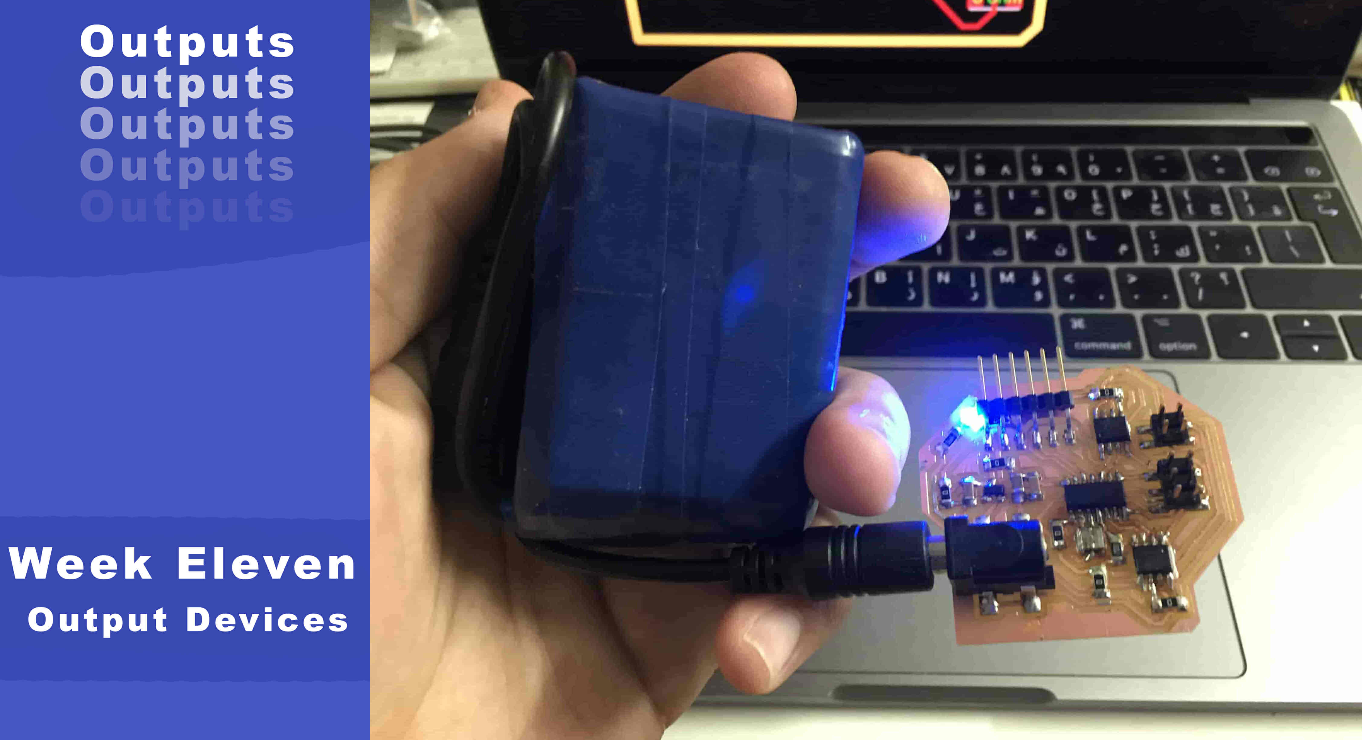
Output Devices
What’s Going On?
Hello People! This week is all about controlling outputs like screens, motors, LEDs, speakers, ...etc. After reviewing Prof. Neil’s lecture I found controlling some motors and displaying some data on an OLED screen about the motor movement like how many rotations did the motor rotate or the rotation speed a bit more interesting than the other stuff that got covered in the lecture.
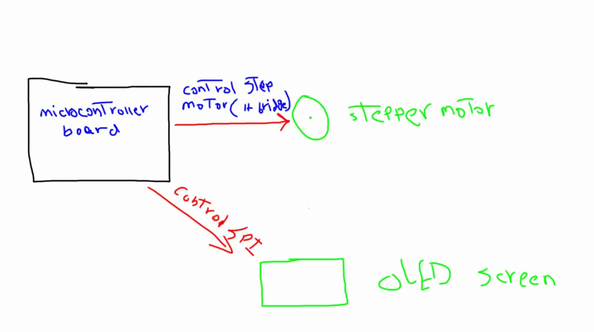
So, I decided to design and make a board that drives a stepper motor through dual H-bridges. Not only that, but the board will also be able to control an OLED screen too through the SPI protocol.
The hardest part that takes most of the time is understanding the circuit that you will build which directly determines if your circuit will work at the end or not. In order to achieve that, we need to look a Lil bit closely about the hardware that we need to control. The stepper motor, and the OLED screen.
Stepper motors are used widely in applications that need a precise and accurate movement like 3d printers, and CNC machines. That’s because it has high torque and you can control how many steps you need the motor to move. not only that, but you can also make the motor movement smoother by controlling how many micro-steps the motor moves which is a great advantage.
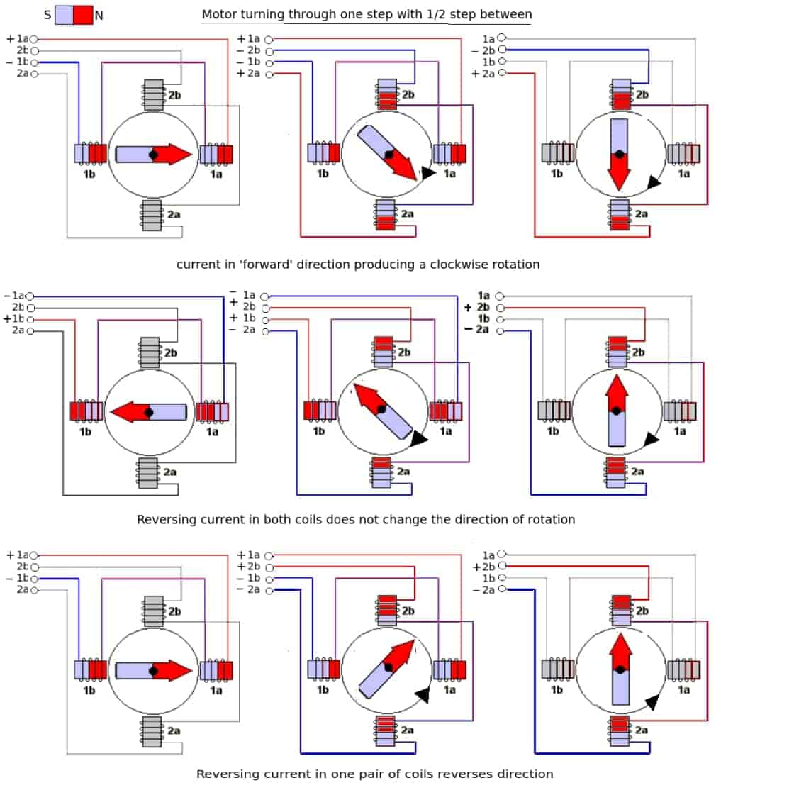
Stepper motors generally have a magnetized geared core that is surrounded by a number of coils that act as electromagnets. Despite the number of coils, electrically there really are usually only two coils in a stepper motor, divided into a number of small coils.
By precisely controlling the current in the coils, the motor shaft can be made to move in discrete steps. Actually, if you wanna know more details about Stepper motors you can check this amazing video.
In today’s project, we gonna use a bipolar stepper motor which consists of two coils of wire (electrically, actually split into several physical coils) and generally has four connections, two per coil as we can see that in the motor datasheet. An advantage of bipolar stepper motors is that they make use of the entire coil winding so they are more efficient. But, In a unipolar stepper motor only half of each coil is used at one time. We gonna use specifically a NEMA17 stepper motor,
NEMA is an abbreviation for the National Electrical Manufacturers Association. Although based in the United States this is actually an international standards committee, although being American the specifications were all originally created using the imperial system instead of the metric system. The “17” in “NEMA 17” is the faceplate size, in the NEMA standard, the faceplate is the NEMA “number” divided by 10 in inches. So a NEMA 17 motor has a faceplate approximately 1.7 inches wide while a NEMA 23 is 2.3 inches wide. Also, we can see in the datasheet the faceplate size is 42.3mm which is 1.7inch approximately.
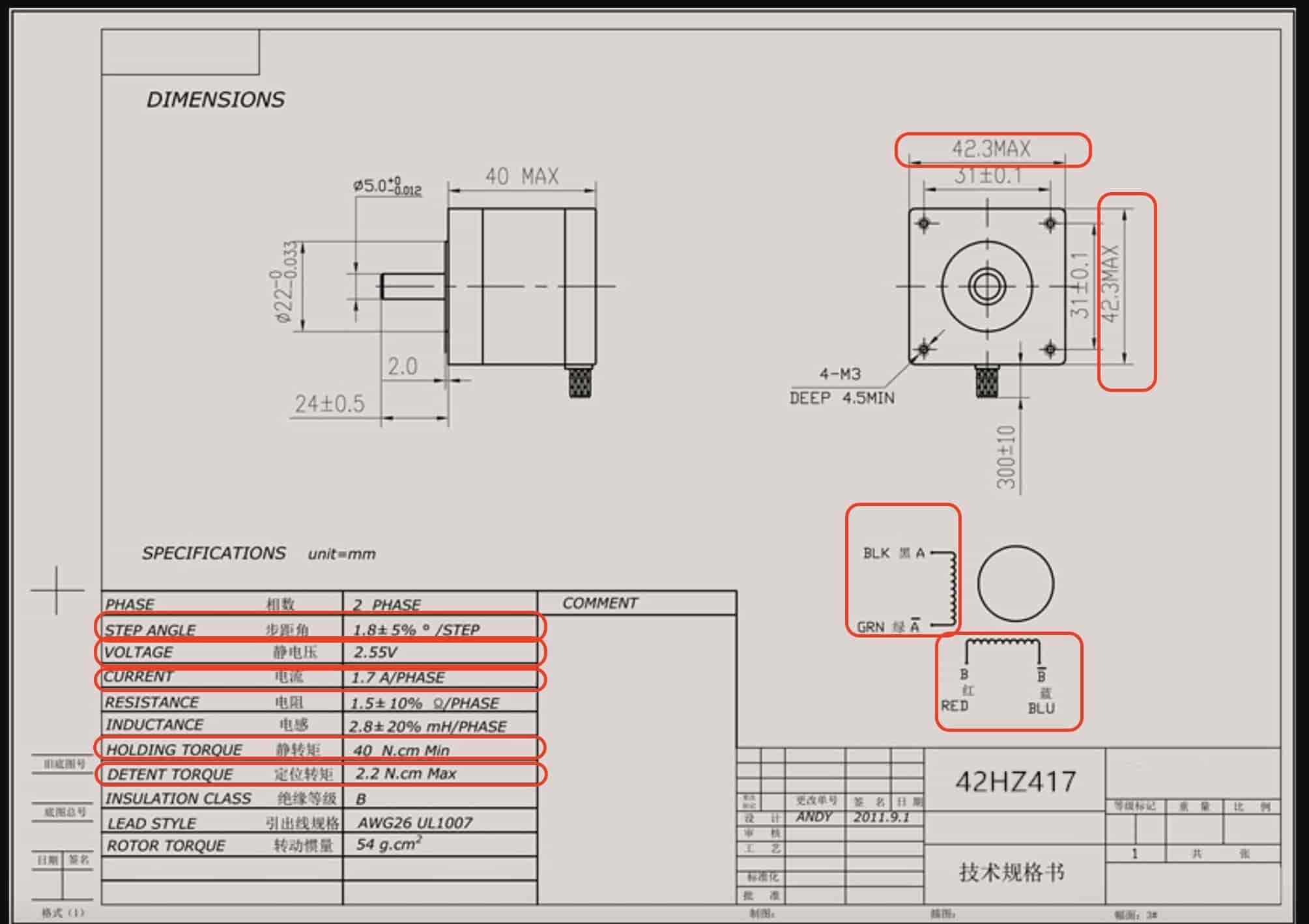
A 1.8° stepper motor is the amount that the shaft of the motor will spin in one full step. Since the full revolution has 360° that means a 1.8° stepper motor has 200 steps per revolution. (360(degrees/rev) / 1.8(step angle) = 200 steps/rev)
That motor works well with 9v/12v supply voltage and consumes current about 1.7A at maximum torque.
Stepper motor and DC motor control using H-bridges
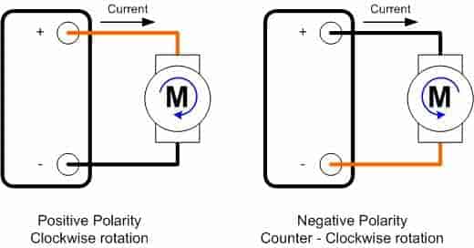
First, let’s talk about how to control DC motors to understand some main concepts, DC motors simply consist of a coil and magnet. The DC motor will start rotating only when a current flow through that coil, the motor rotation direction depends on the current flow direction. By changing the polarity of the power source with the motor, the motor rotation direction will get reversed. (NOTE: DC motors have no polarity.)
But, how to control the DC motors from a microcontroller board? Actually, DC motors draw a large amount of current while rotating, up to 500mA (it depends on the motor size and its power rating), but our small ATtiny44 board only can provide 40mA at 5V on its digital pins. so we need to use an external power source(battery) to provide the motors with the required power to operate properly without damaging the ATtiny44 board. Also, we need to separate that power circuit(External power source) from the control circuit(ATtiny44 Board).
- We will use a 12V 4Ah battery as a power source to provide the required power to our motor (power circuit).
- And, of course, the ATtiny44 board to control the motors (control circuit).
A simple solution to separate the control circuit from the power circuit is to use a transistor.
In the above circuit, we are using the transistor as a switch, when the voltage across the base-emitter transistor is HIGH (5V) it will close the connection between the collector and the emitter. So, the current will flow through the motor which will make it rotate.
If the voltage across the Base-emitter transistor is LOW (0V) it will open the connection between the transistor collector and emitter and the motor will stop rotating. It’s very important to use a current limiting resistor on the transistor base pin (1k Ohm) to prevent it from damaging. Also, use a diode in parallel with your motor to protect the ATtiny44 from any back EMF returning from the motor.
But this circuit will allow us to only control the motor only ON and OFF without controlling the rotation direction. So, what if we want to control its rotation direction? The answer is an H-bridge circuit.
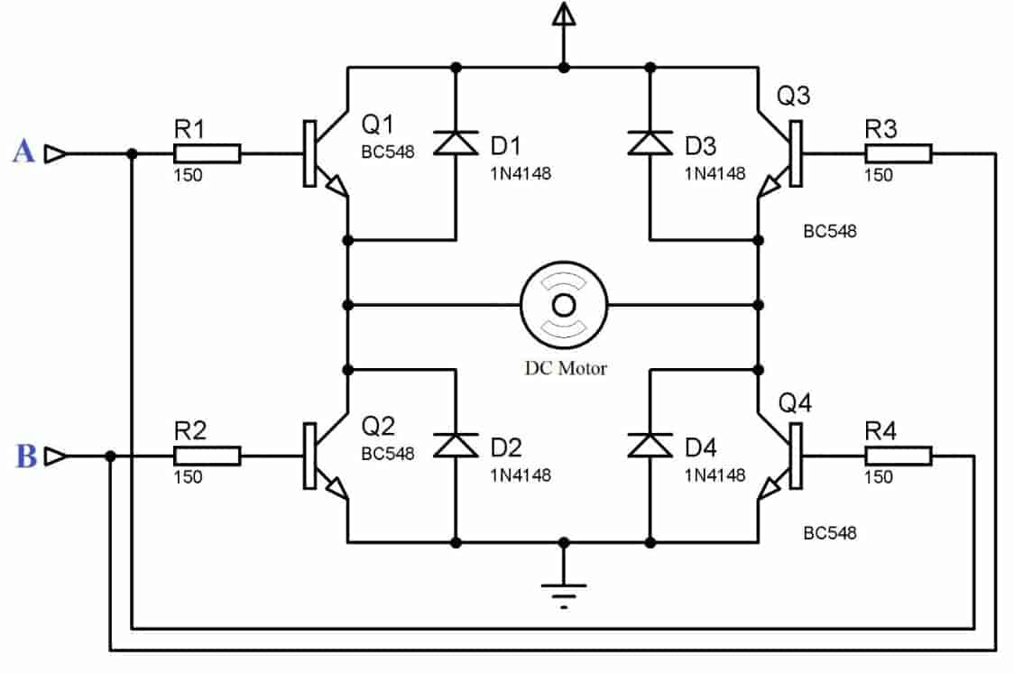
Simply, the H-bridge circuit inverts the direction of the current flow through the motor. this circuit contains four switching elements(transistors in our case) by activating two particular switches at the same time we can change the direction of the current flow thus change the motor rotation direction. for example:
- When Q1 & Q4 are activated and the Q2 & Q3 are deactivated, the current will flow from the VCC of the power source passing through the Q1 then to the motor(from the left terminal to the right terminal) then to Q4 then to the GND. which will make the motor to rotate in the clockwise direction.
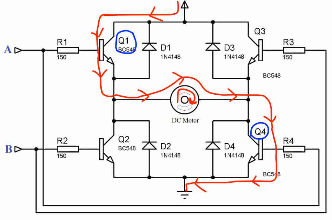
- When Q2 & Q3 are activated and the Q1 & Q4 are deactivated, the current will flow from the VCC of the power source passing through the Q3 then to the motor(from the right terminal to the left terminal) then to Q2 then to the GND. which will make the motor rotate in the anti-clockwise direction.
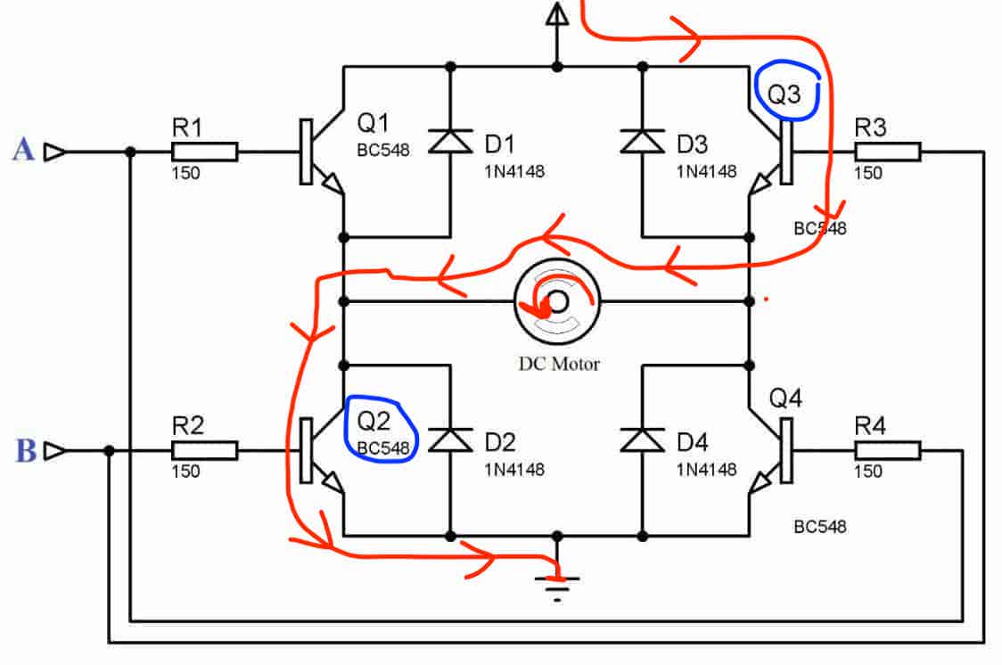
So, using only two output pins(A, B) from the ATtiny44 board you can control the state of the four switching elements(transistors) thus controlling the motor rotation direction.
- 'A' pin Controls transistor Q1, and Q4.
- 'B' pin Controls transistor Q2, and Q3.
DC and Stepper motors Control Board design Logic
Basically, I wanna design a board that can drive two DC motors or one stepper motor and control an OLED screen to display some data. To control DC motors rotation speed and direction we need an H-bridge circuit, the same also with the stepper motors. Since we are using a bipolar stepper motor which has two coils, So we need two H-bridges, one for each coil. We can design our H-bridge circuit using some MOSFETs and protection diodes or using an H-bridge IC like the awesome Allegro A4953 H-bridge IC.
I decided to use two A4953 H-bridge ICs with an ATtiny44 microcontroller and a 12V 4Ah power source. But, before any designing work, let’s take a look at the Allegro A4953 IC and see it’s datasheet to make sure that this part is suitable for our purpose.
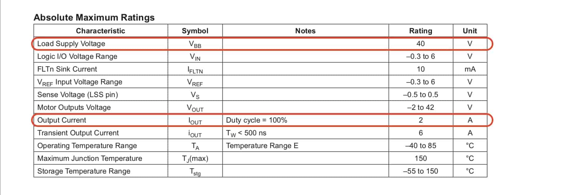
When you open your datasheet, you will see a short description of the IC which helps you to get a good overview of the device itself. As we can see from the description, it can handle upto 2A and works on maximum 40V. Which are good values for our application.
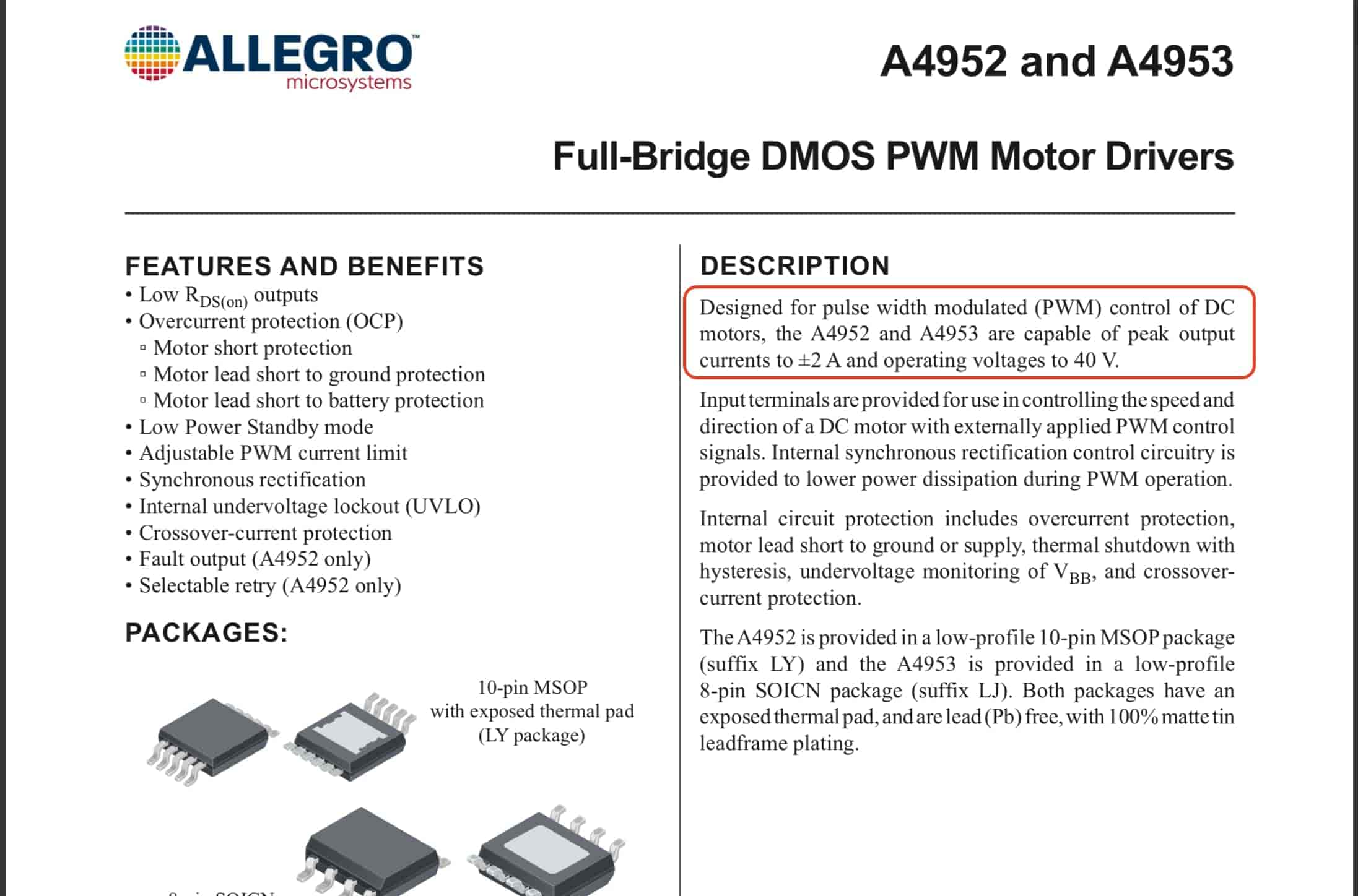
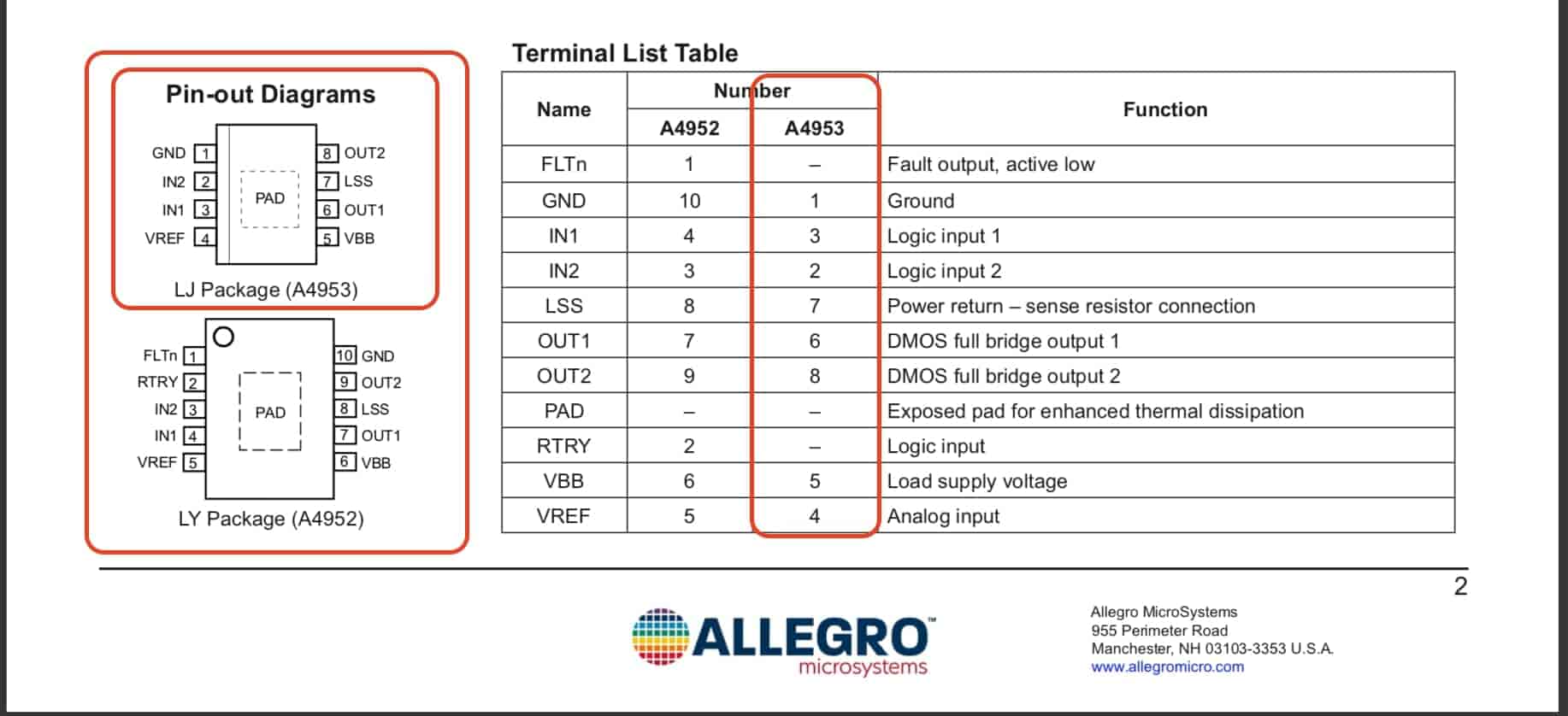
Second important thing is to know the pinout of the IC which pin is which. In the datasheet we can see that this device comes in two different packages/versions(A4953, A4952) since we gonna use the A4953, it has 8-pins two is for power(VBB, GND) VBB pin is the motor power supply, two for controlling the H-bridge mosfets(IN1, IN2) which control the motor rotation direction. And the motor output pins(OUT1, OUT2) which connect to the motor coils to control the current flowing through it.
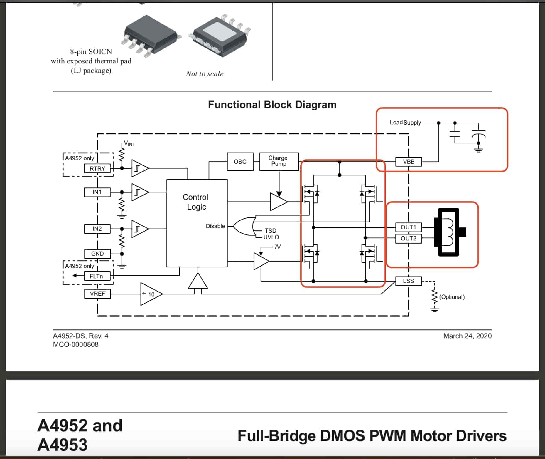
Also in the datasheet we can find a functional block diagram that describes the logic/architecture and how things are connected together internally inside the IC. we can see an H-bridge made with four MOSFETs. Also, we can see that the VBB pin is connected with the external power source with two decoupling capacitors. The OUT1, OUT2 pins are connected to the motor coil leads. And the IN1, IN2 pins should get connected to the microcontroller output pins to control the MOSFETs state.
Also in the datasheet, we can find the absolute maximum rating table that covers all the electrical specs you need to know.
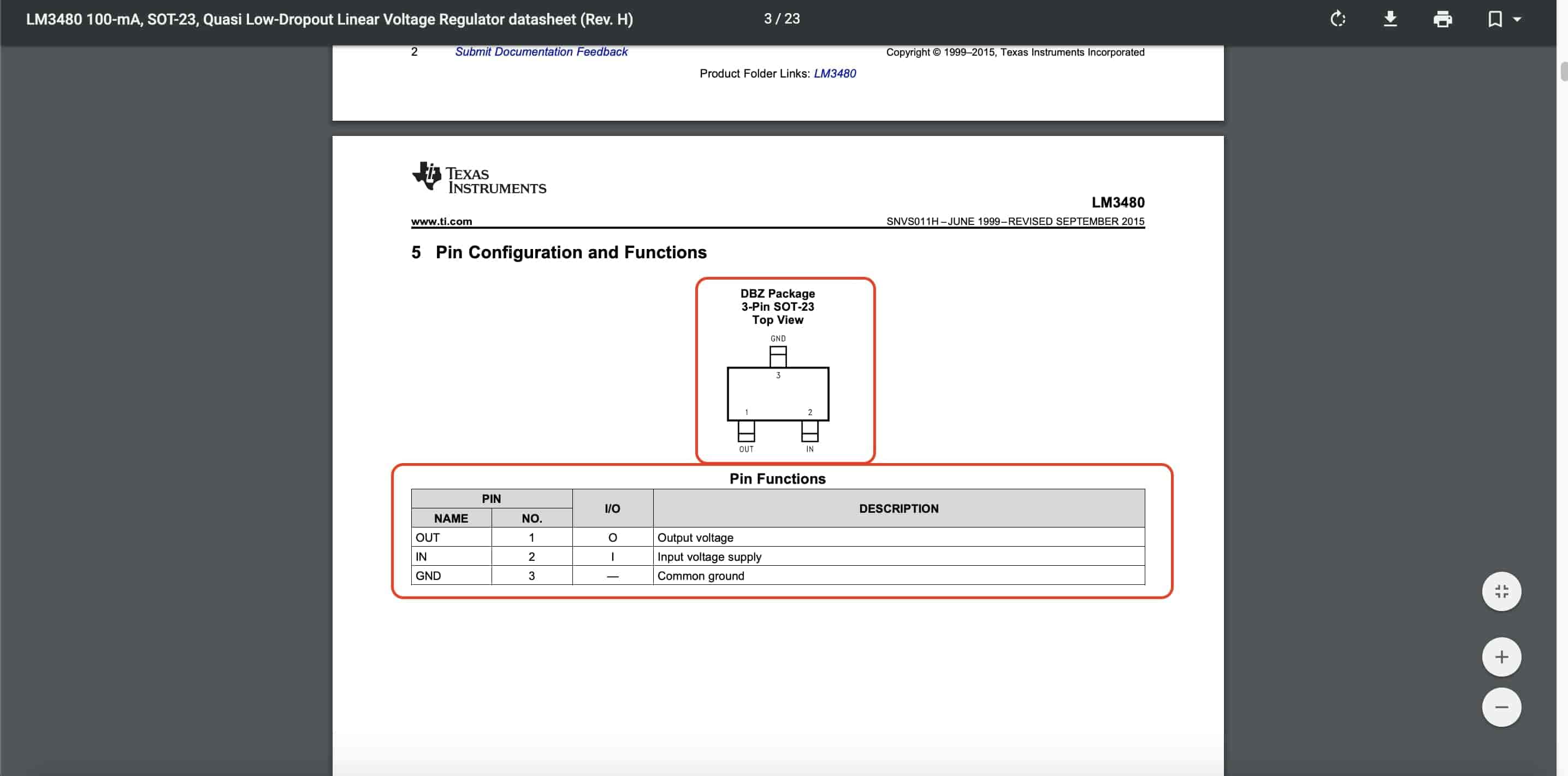
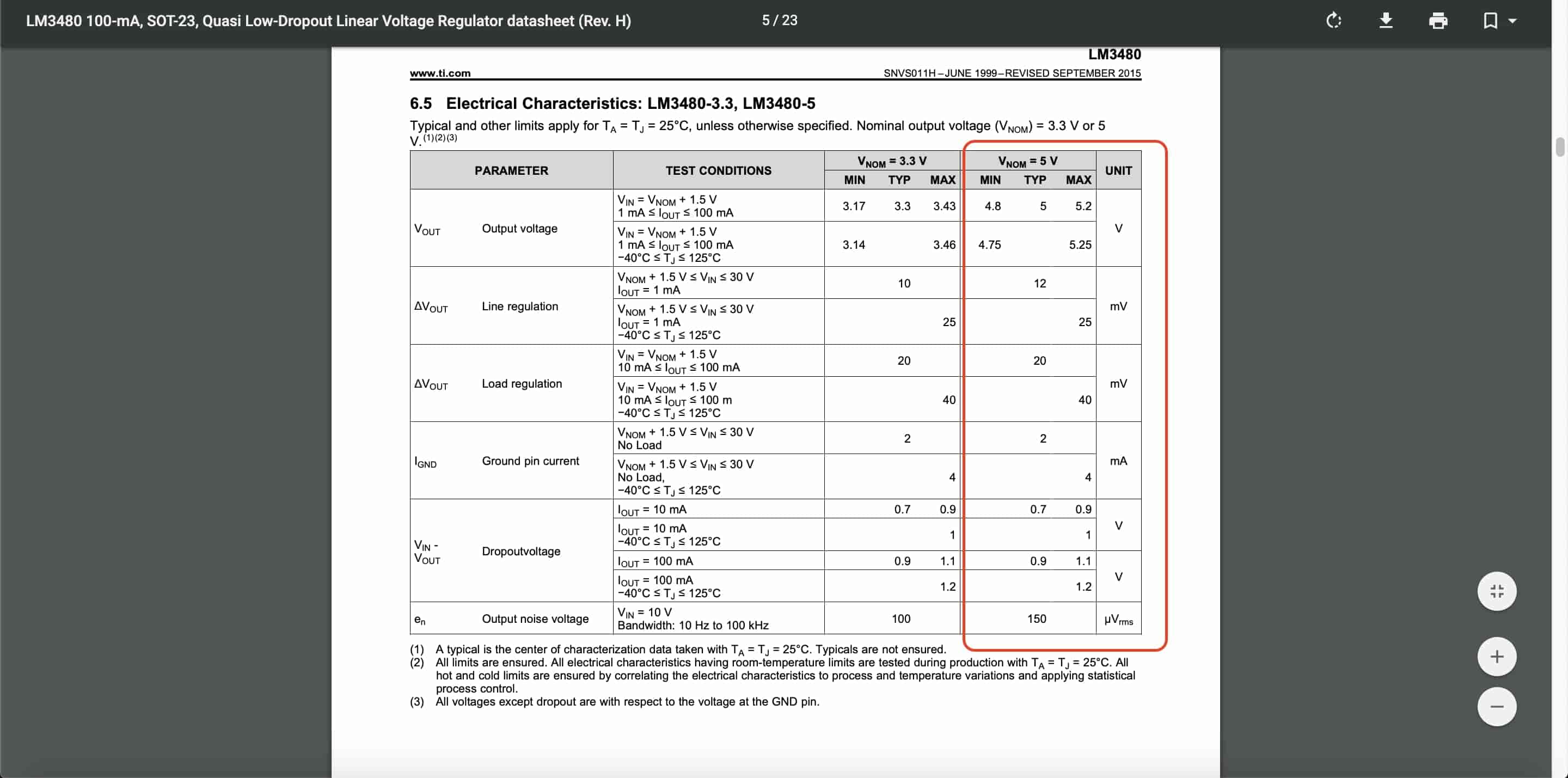
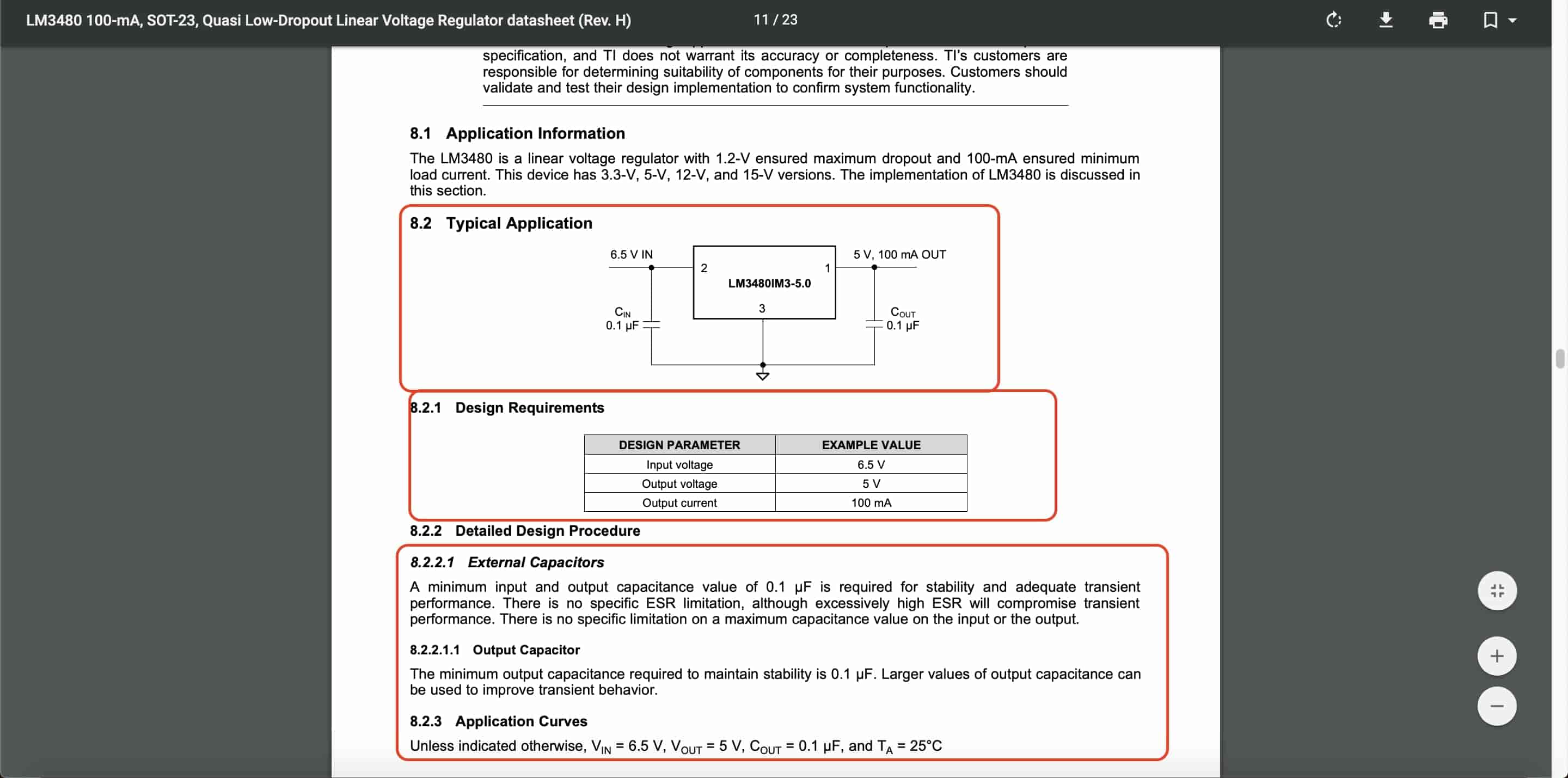
Since we are going to use a 12V power source we need a voltage regulator to be able to provide a clean 5V to the attiny44 microcontroller. So after looking at the fab inventory I found the LM3480 5V 100mA voltage regulator is a good option for our purpose. After looking at it’s datasheet, knowing the pinout and the typical application of it, it’s now easy to start designing my board.
A very important note here is the input and output minimum 0.1uf capacitors are required for electrical stability.
PCB Designing
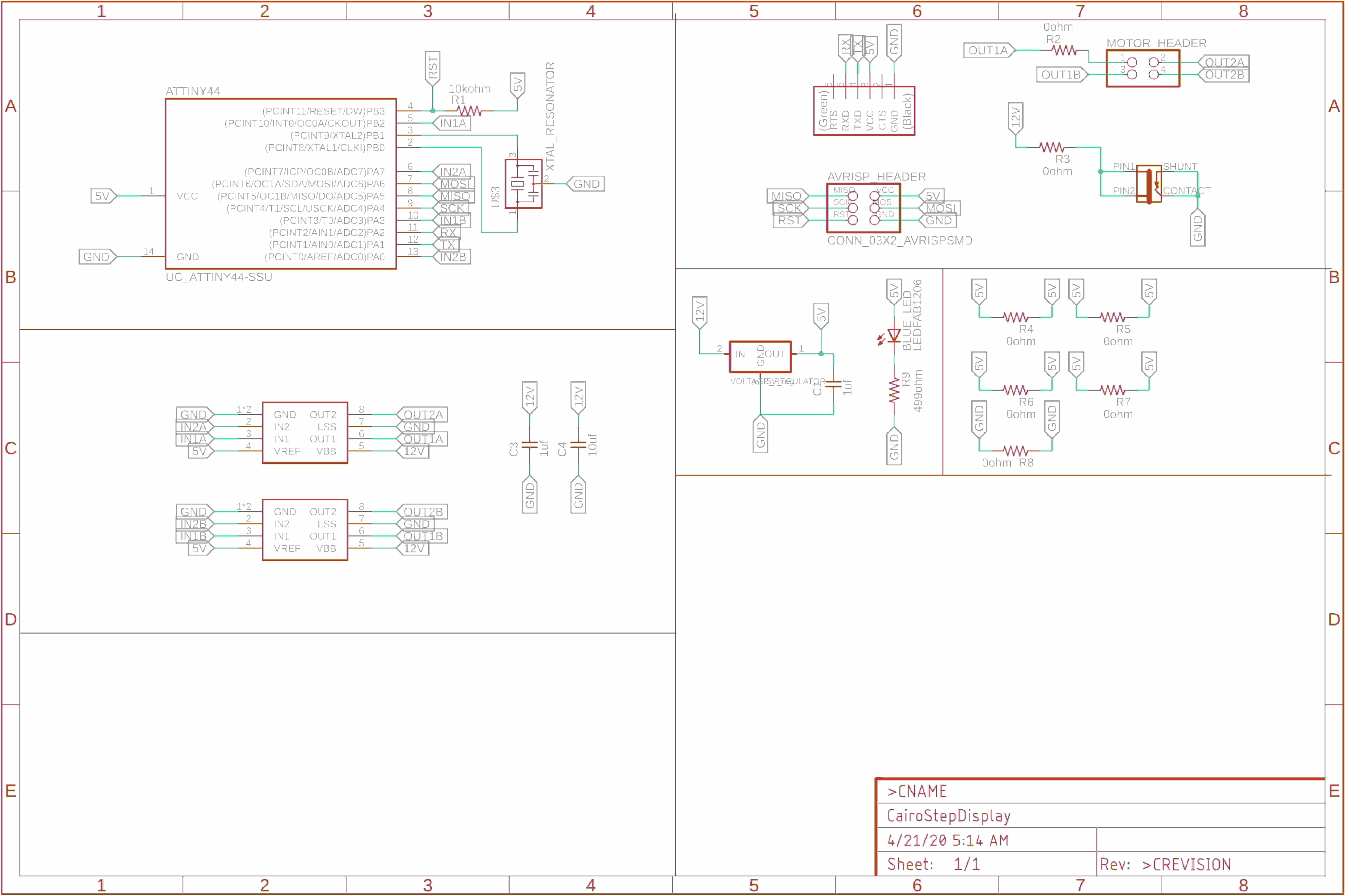
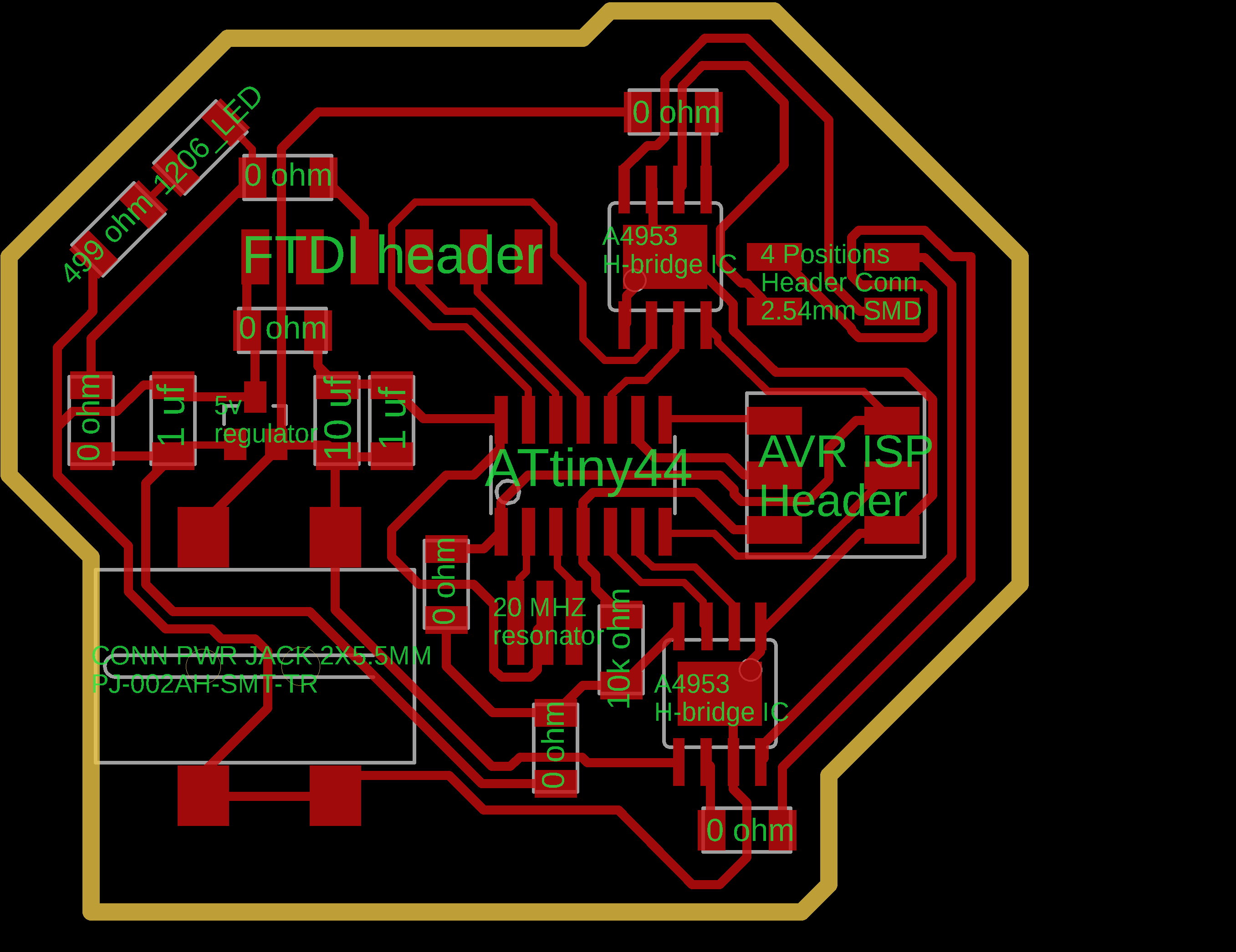
After choosing the suitable hardware and building a good overview on how to use each component by reading its datasheet, I opened my buddy، Eagle. And started designing my board. Started by inserting all the components in my workspace. Then started connecting all the componenta with each other.
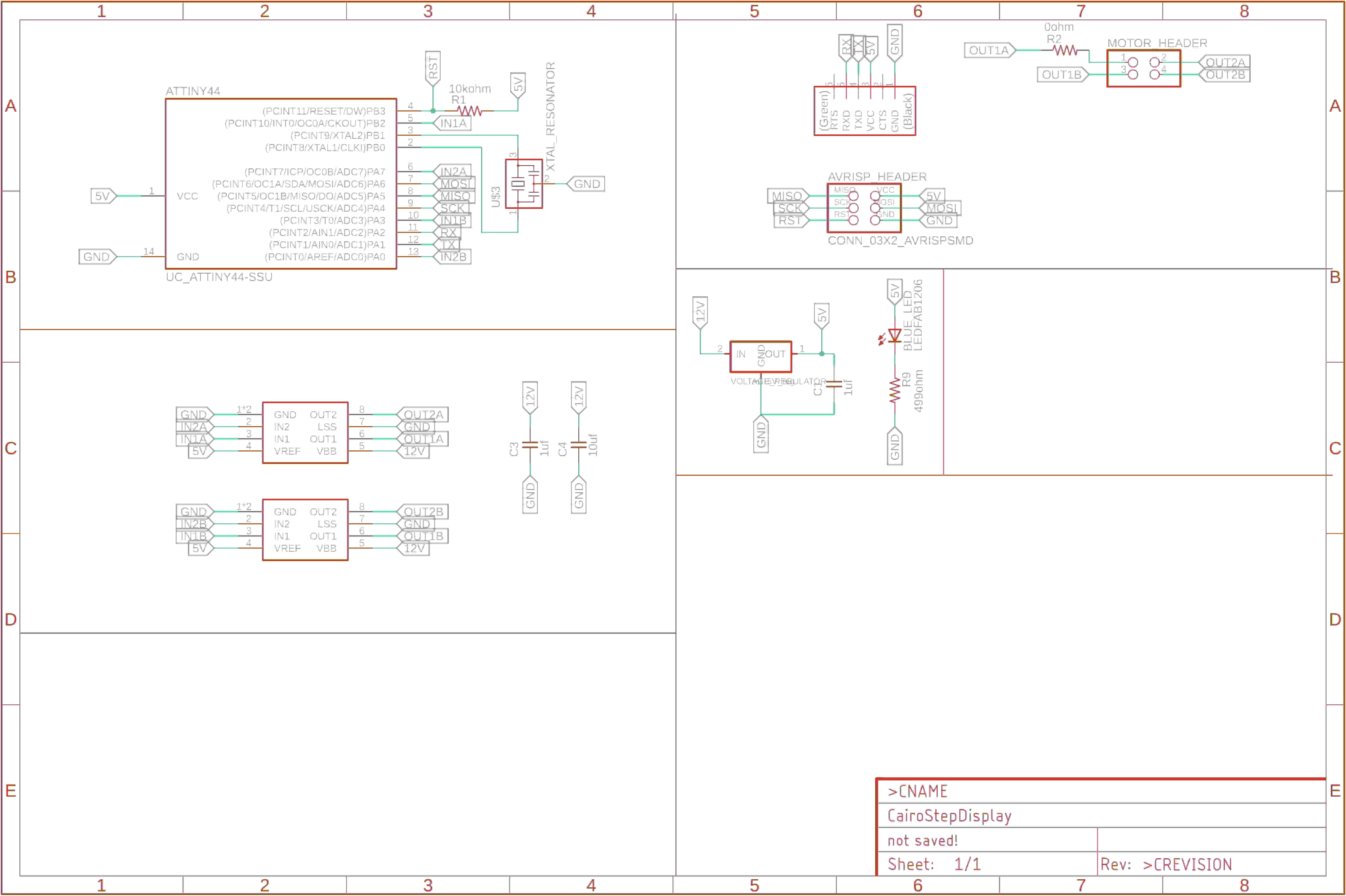
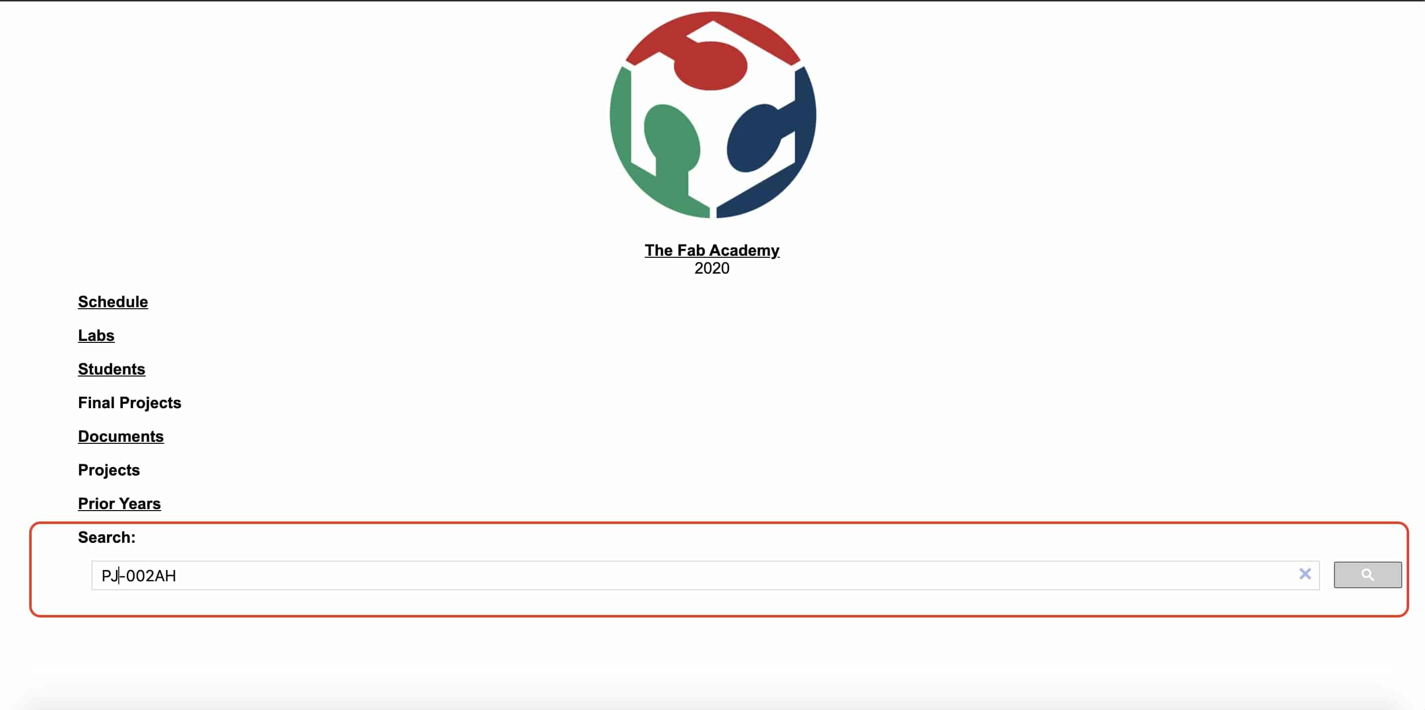
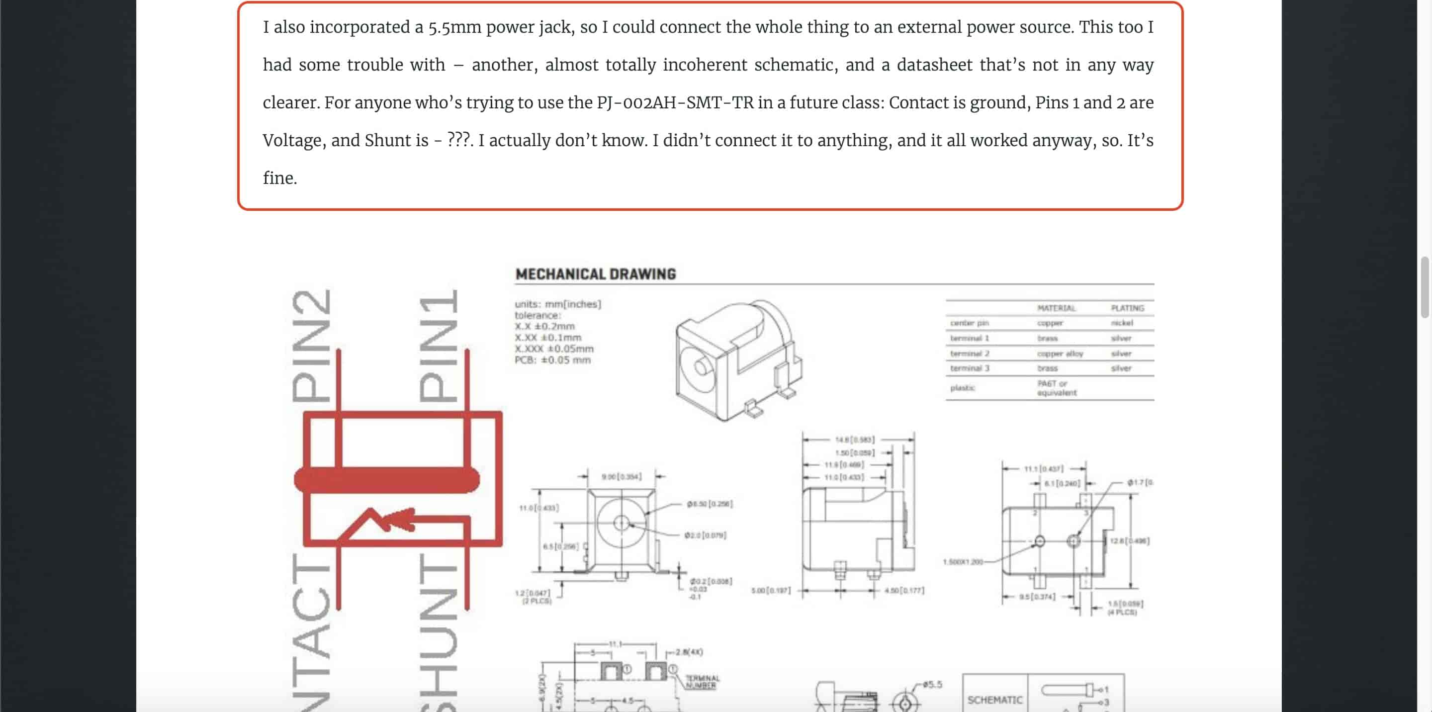
Until now I'm thinking about what type of connector or jack I will use to connect my circuit with a 12V external power source. I want to use an SMD power jack instead of the 2x2 pin connector. I looked at the Fab Lab Egypt inventory and searched for it. And I found it. The connector power jack 2X5.5mm(PJ-002AH-SMT-TR). But, I don’t know what is it’s pinout, which pin is the positive and which is the ground! I opened it’s datasheet, it's not clear at all and still don’t know it’s pinout :D I searched in the prior years about the term “PJ-002AH” and found this page. Nicole is facing the same problem with the same connector :D but he figured it out and mentioned that PIN1, PIN2 are the voltage, and the CONTACT terminal is the ground. That’s all what I need. Thanks Nicole <3
I inserted the power jack in my workspace and connected its voltage terminal to the voltage regulator VIN pin, and to the VBB pin of the two H-bridge ICs.
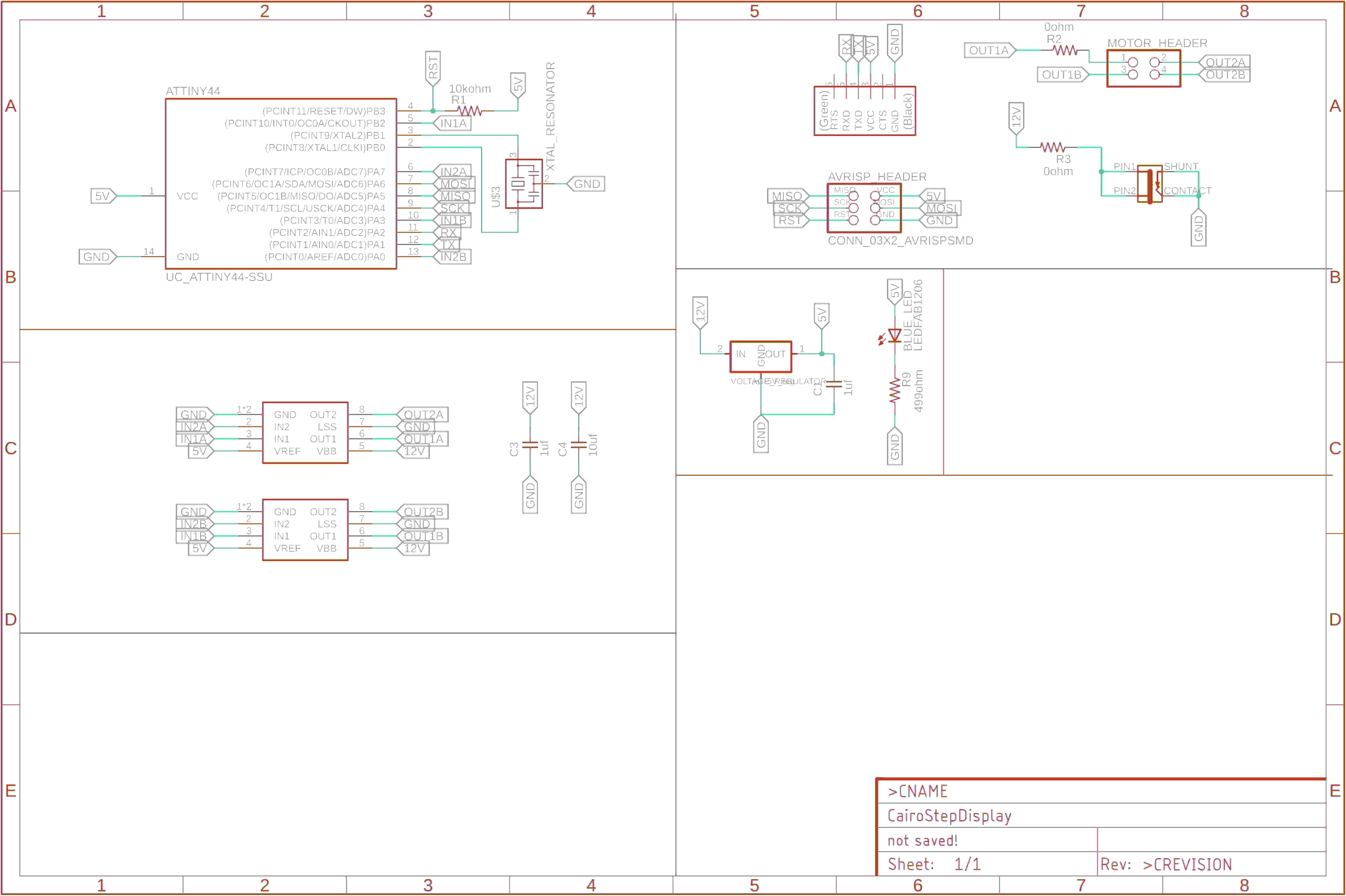
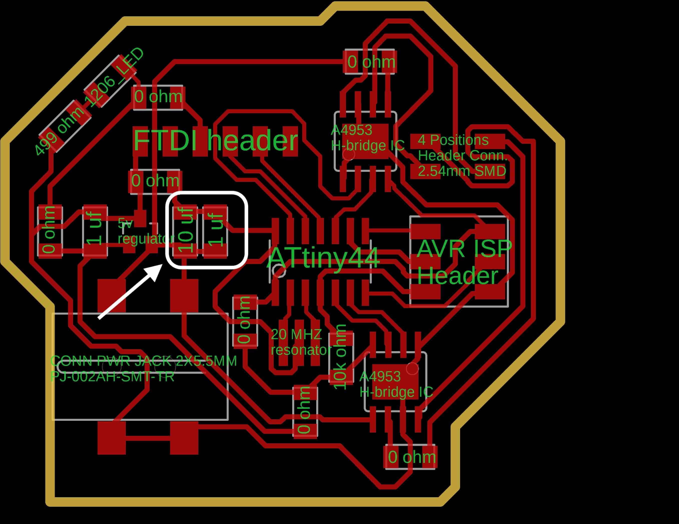
After finishing my schematic, I converted into the board layout. I placed the components near to it’s relatives and Started the routing process. It wasn’t very easy, I faced some problems Which forced me to add some bridges(0 Ohms resistors) in my schematic. Then I finished the board layout and it’s now ready to get fabricated. VOILA!
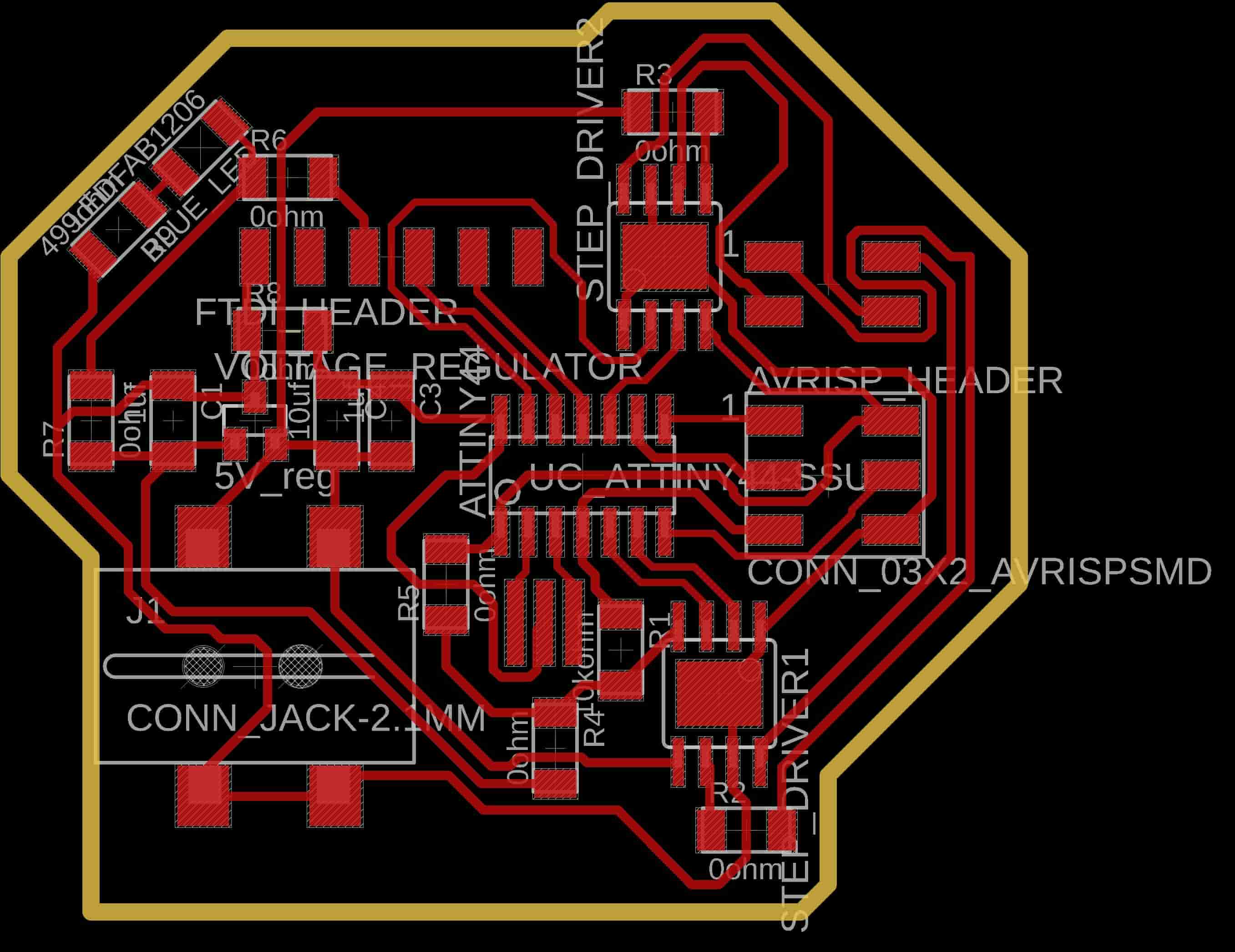
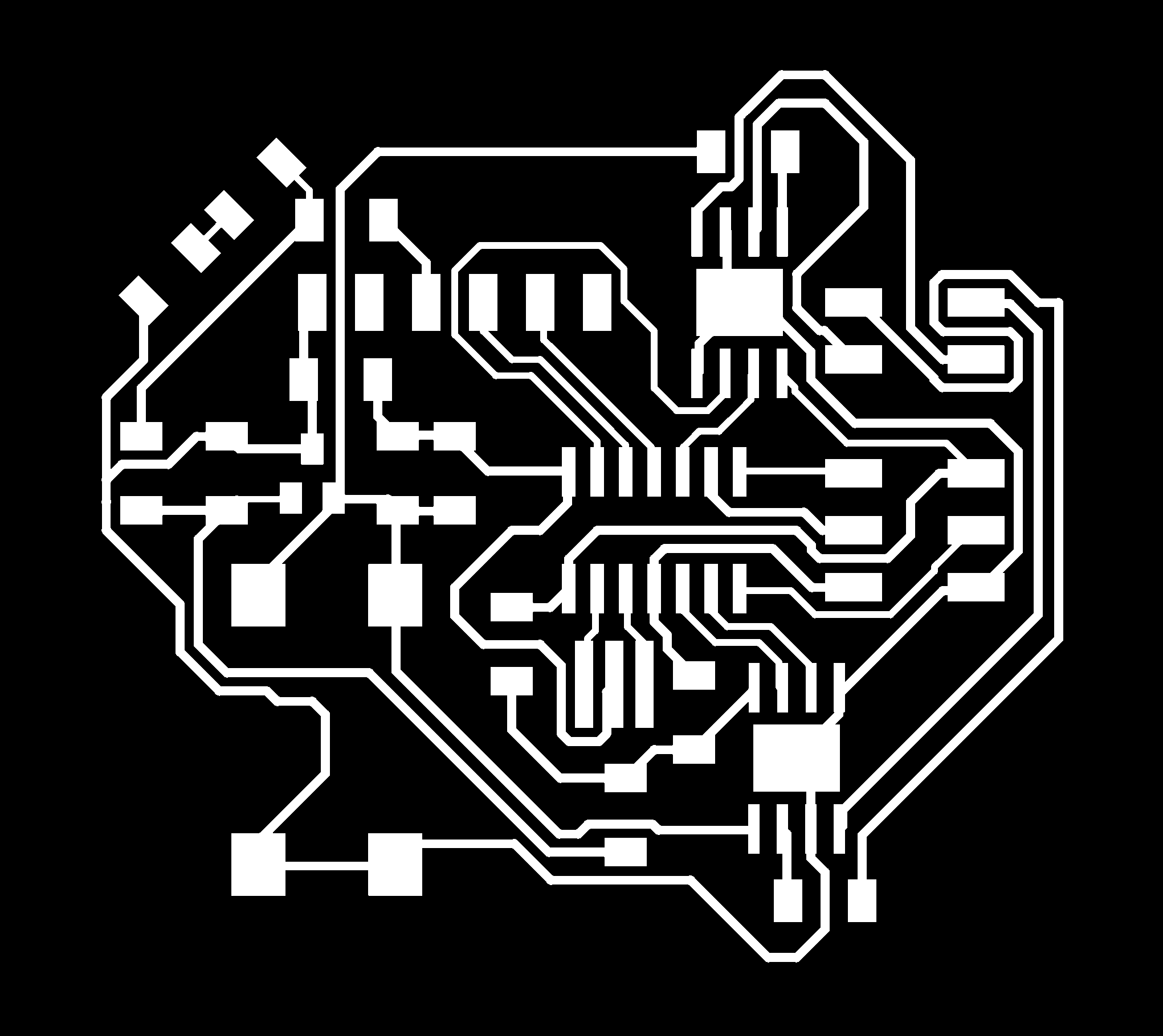
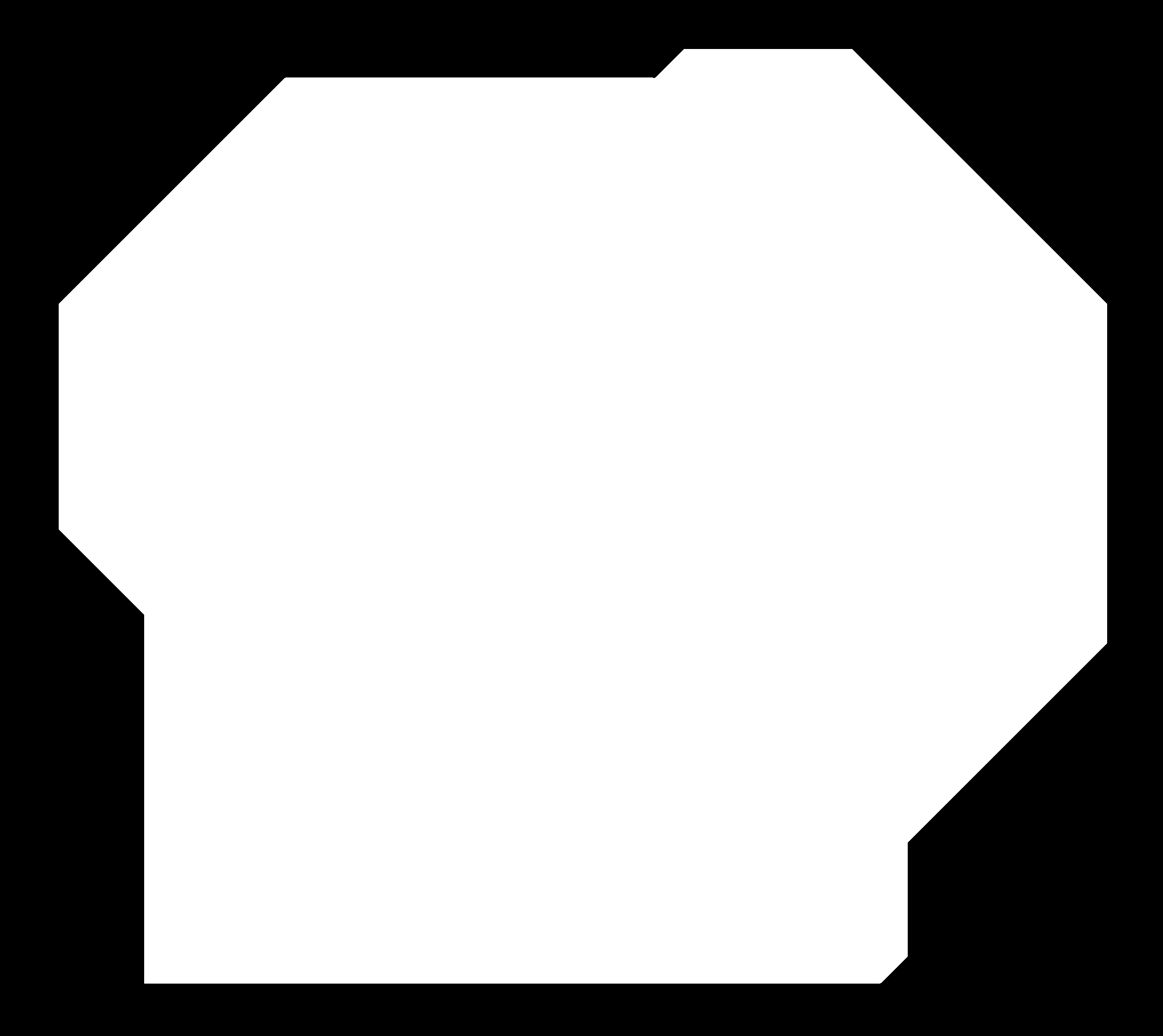
PCB PNG Files Download
PCB Fabrication
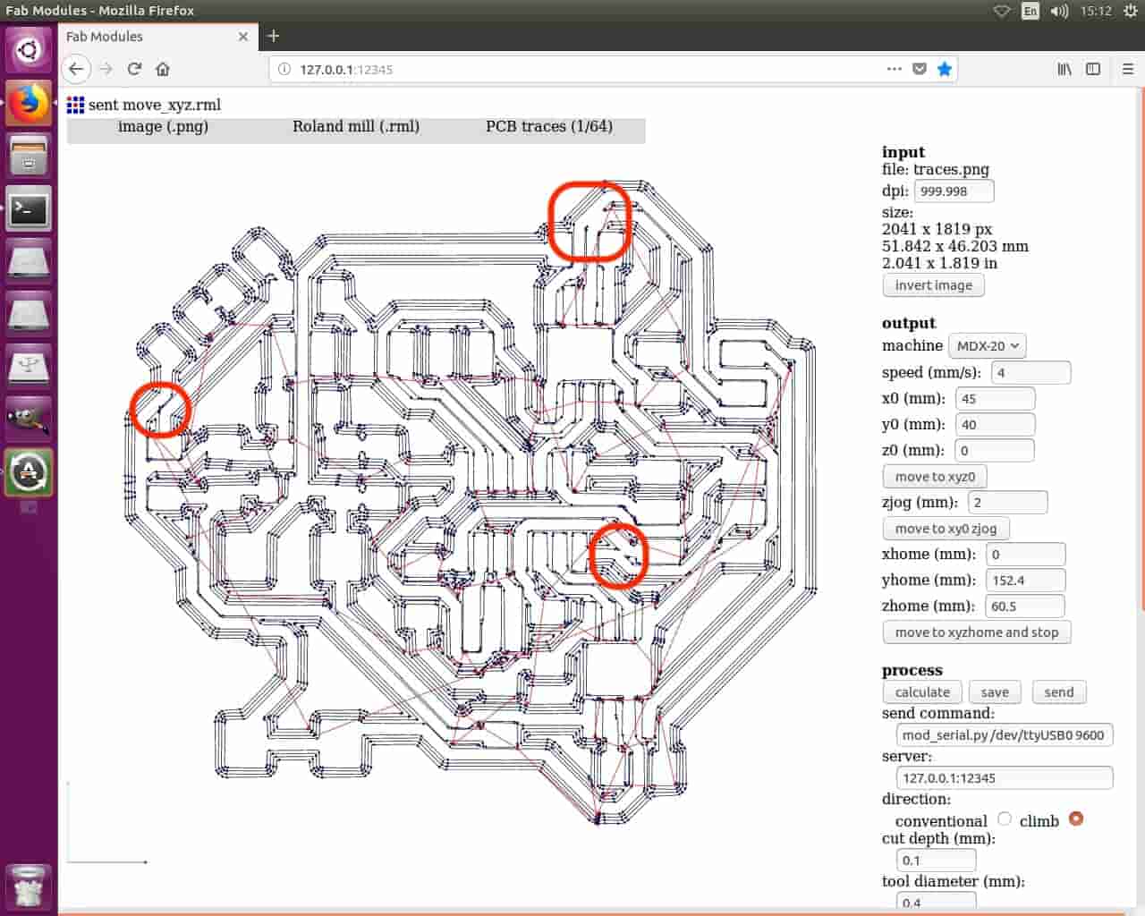
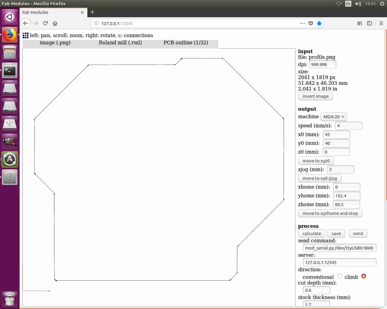
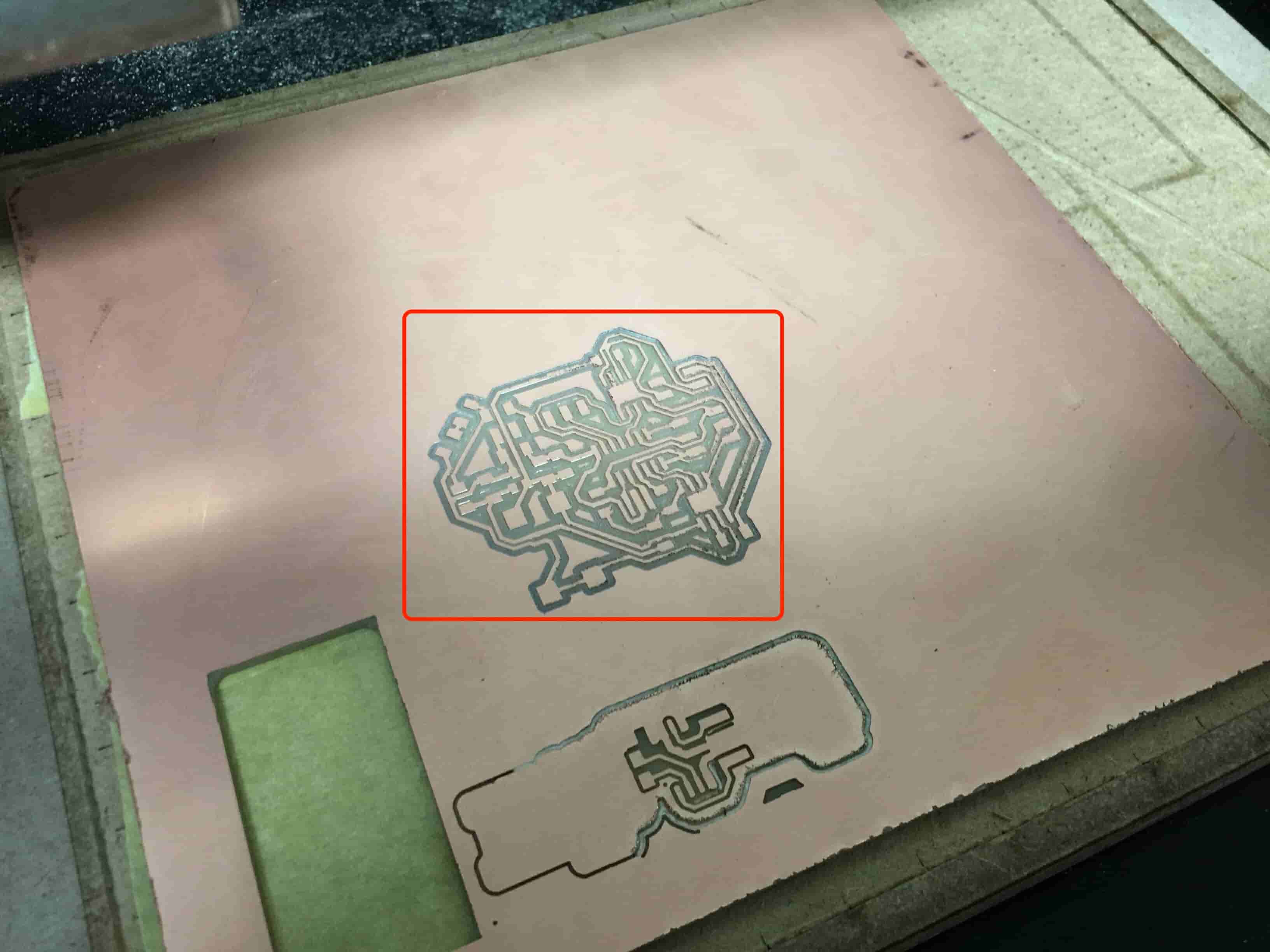
The Fab Modules CAM software that we are using at Fab Lab Egypt needs PNG images for your board traces and profile to start generating the Gcode for the awesome Modela to do it’s work. To export these files, we need to use some extra softwares(GerbV, GIMP) to do some post processing to export these PNG files. For more details about this part, check out the Electronics Design week assignment.
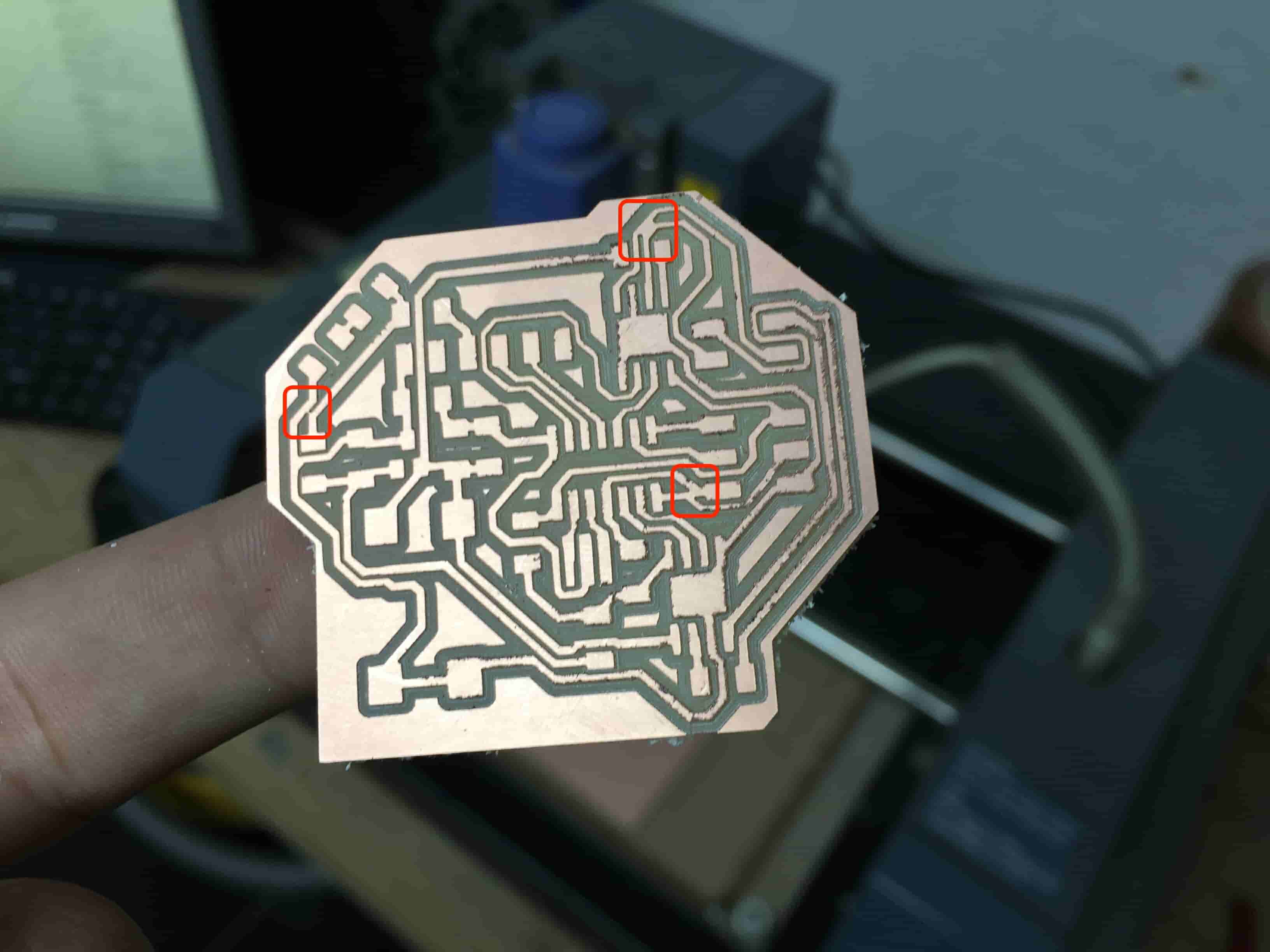
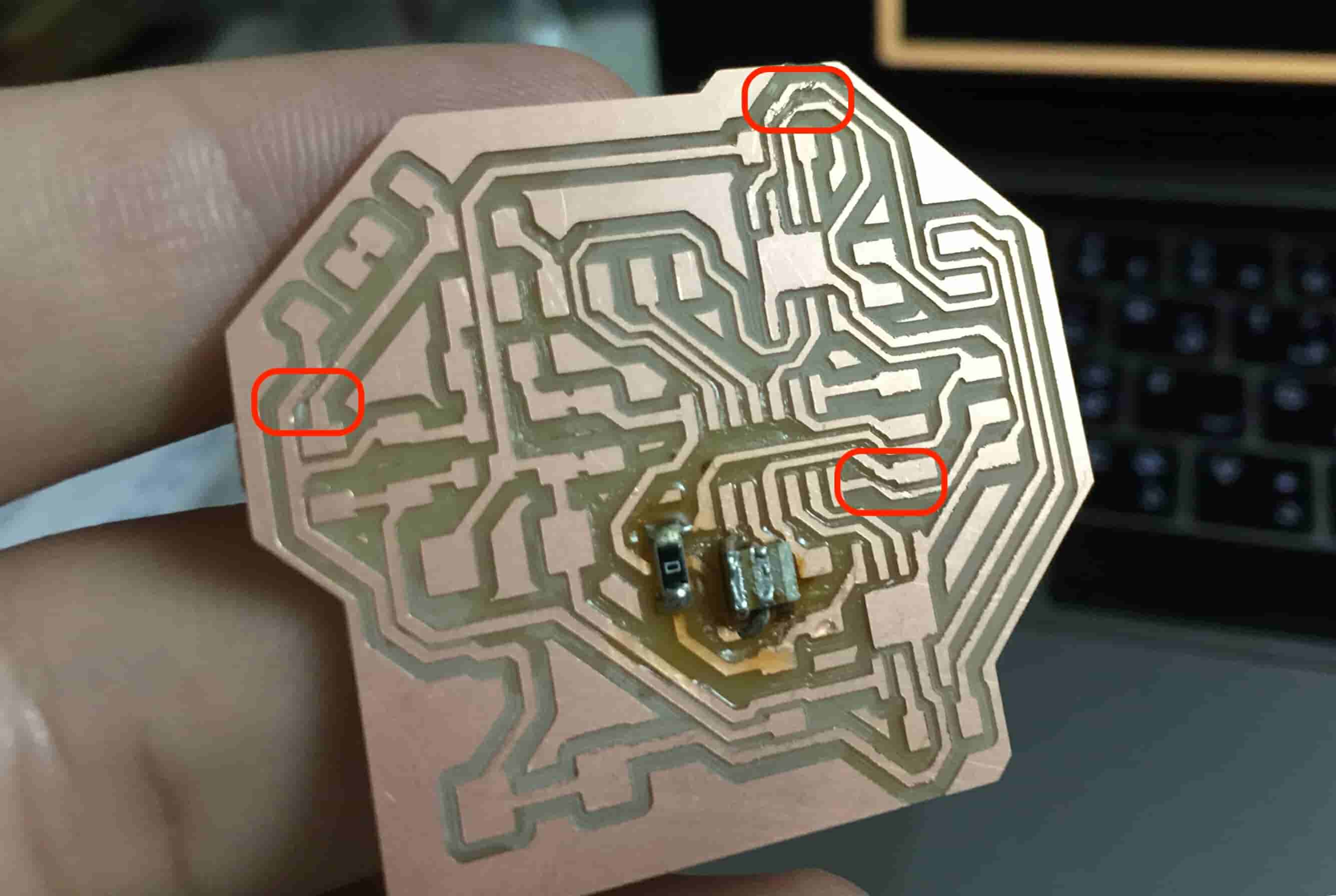
Before sending the job to the machine, I noticed some short circuits in the board. Which is bad! Ok, I will cut these short circuits later with a cutter or something.
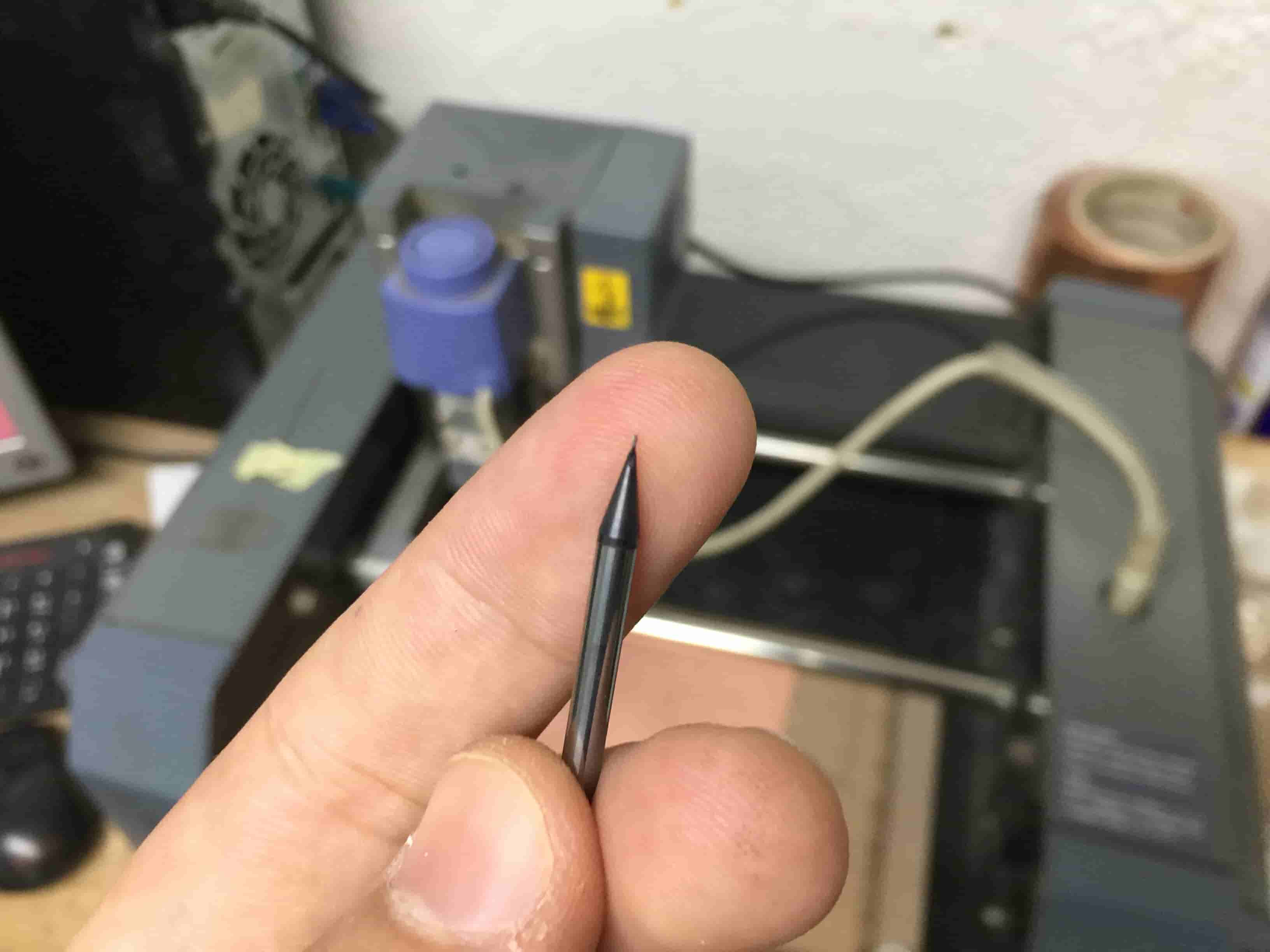
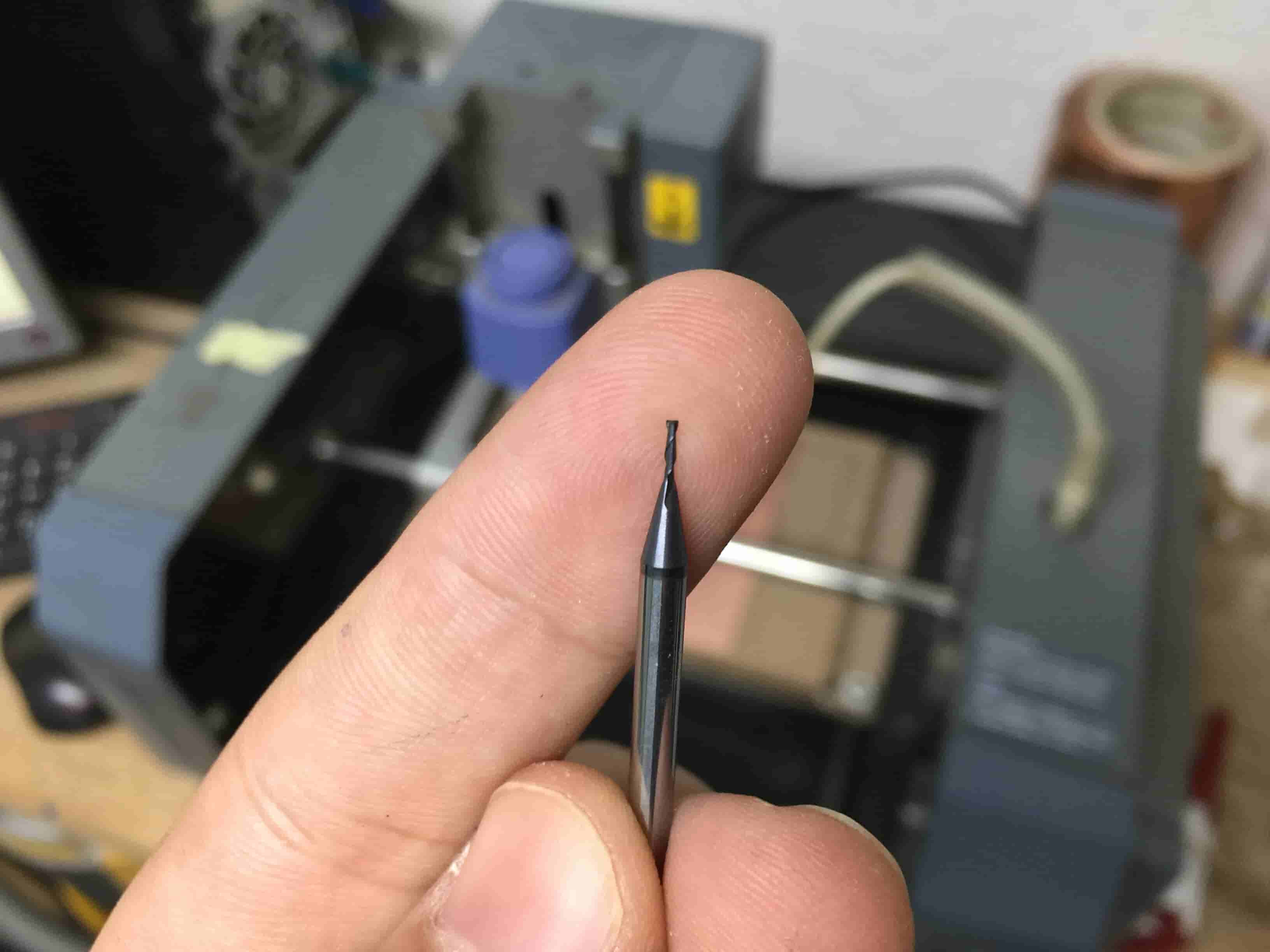
I installed the PCB on the machine bed with a double face tape. Make sure the board is flat on the bed without any elevated parts. If the board is not flat on the machine bed, the probability of breaking the endmill will be very high.

To engrave the PCB traces we are using a 1/64inch end mill. And a 1/32inch end mill to cut the board outline.
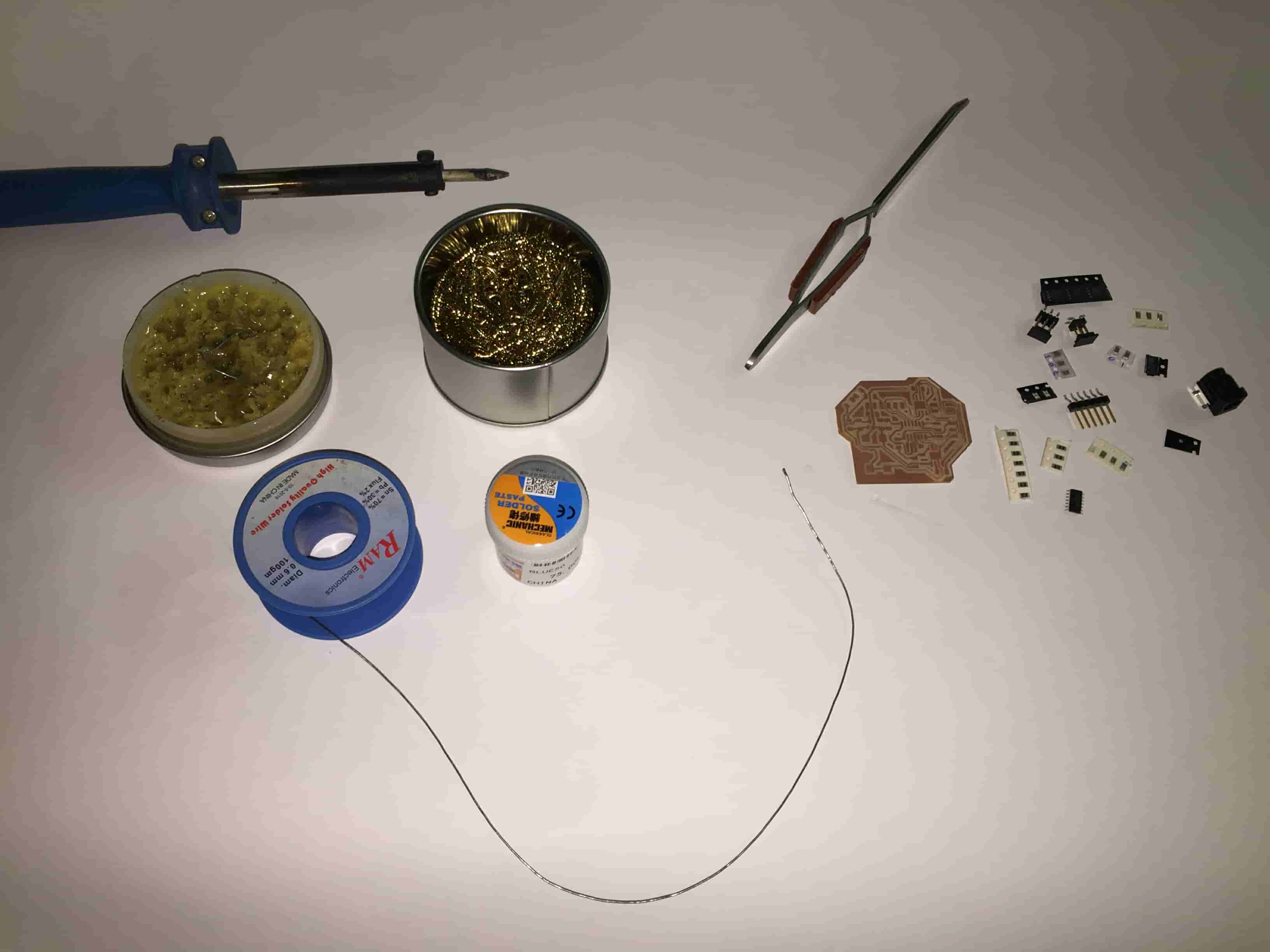
Now it’s time for soldering. The most exciting part for me is getting the hardware from the inventory and stuffing it. Since we are in quarantine in Egypt, this week soldering will be at home. Here’s a list with the used hardware.
| Part Number | Description | Quantity |
|---|---|---|
| ATTINY44A-SSU-ND | IC AVR MCU 4K 10MHZ 8SOIC- | 1 |
| XC1109CT-ND | CER RESONATOR 20.00MHZ SMD | 1 |
| S1143E-36-ND | SMT RT Angle Male Header 0.1" (36pos) | 1 |
| 609-5161-1-ND | 6 Positions Header Connector 0.100" SMD | 1 |
| 609-5160-1-ND | 4 Positions Header Connector 0.100" (2.54mm) Surface Mount | 1 |
| 587-1352-1-ND | CAP CER 10UF 35V Y5V 1206- | 1 |
| 445-1423-1-ND | CAP CER 1UF 50V X7R 10% 1206- | 2 |
| 620-1428-1-ND | IC PWM MOTOR DVR FULL 8SOIC | 2 |
| 311-10.0KFRCT-ND | RES 10.0K OHM 1-4W 1% 1206 SMD | 1 |
| 311-499FRCT-ND | RES 499 OHM 1-4W 1% 1206 SMD- | 1 |
| 160-1889-1-ND | LED BLUE CLEAR 1206 REV MT SMD | 1 |
| 311-0.0ERCT-ND | RES 0 OHM 1-4W 1% 1206 SMD | 7 |
| CP-002AHPJCT-ND | CONN-POWER JACK 2.1MM SMD | 1 |
| LM3480IM3-5.0/NOPBCT-ND | IC 5.0 100MA LDO VREG SOT23- | 1 |
I was about to forget fixing the board short circuits, I cut off the short circuit between the tracks using a cutter. then , I continued soldering.
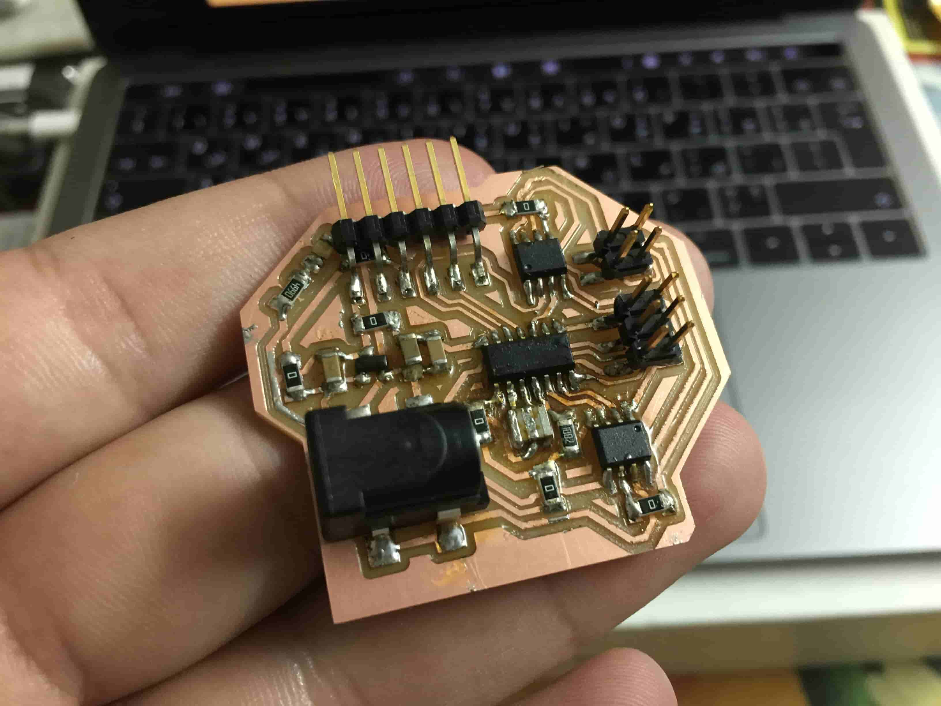
And it turns great! Look how beautiful it is, welcome baby board :D
Board Programming and Testing
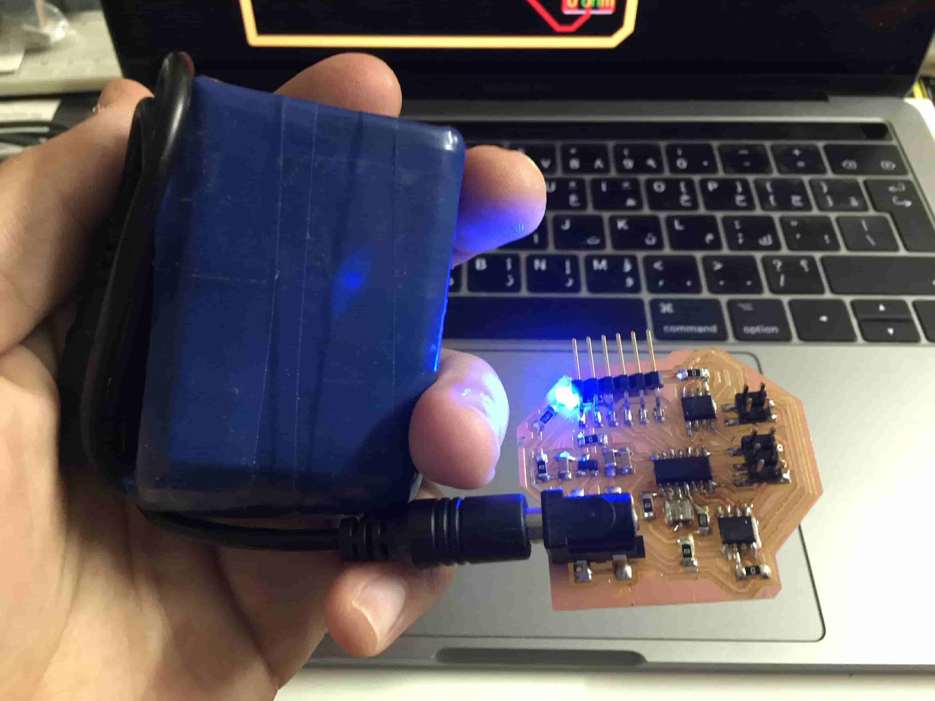
The moment of truth! I will be honest with you, the board looks promising, but it’s not enough. We need to test it with some motors. So, I wrote a simple program that controls a DC motor. The program is very basic and simple, it tells the motor to move forward for one second, stop for a second, move backward for a second, and stop again for a second, then repeat that procedure endlessly as long as the board is connected to a power source.
                #define in1A 3
                #define in2A 0

                void setup() {
                  pinMode(in1A, OUTPUT);
                  pinMode(in2A, OUTPUT);
                }

                void loop() {
                  digitalWrite(in1A, HIGH);
                  digitalWrite(in2A, LOW);
                  delay(1000);
                  digitalWrite(in1A, HIGH);
                  digitalWrite(in2A, HIGH);
                  delay(1000);
                  digitalWrite(in1A, LOW);
                  digitalWrite(in2A, HIGH);
                  delay(1000);
                  digitalWrite(in1A, HIGH);
                  digitalWrite(in2A, HIGH);
                  delay(1000);
                }
Dude! It works just perfect. Now we are sure that the first H-bridge IC is working fine. lets level it up a lil bit. Now, let’s test two DC motors at the same time, to make sure that the second H-bridge IC is also working fine without any problems.
                #define in1A 3
                #define in2A 0
                #define in1B 8
                #define in2B 7

                void setup() {
                  pinMode(in1A, OUTPUT);
                  pinMode(in2A, OUTPUT);
                  pinMode(in1B, OUTPUT);
                  pinMode(in2B, OUTPUT);
                }

                void loop() {
                  digitalWrite(in1A, HIGH);
                  digitalWrite(in2A, LOW);
                  digitalWrite(in1B, HIGH);
                  digitalWrite(in2B, LOW);
                  delay(1000);
                  digitalWrite(in1A, HIGH);
                  digitalWrite(in2A, HIGH);
                  digitalWrite(in1B, HIGH);
                  digitalWrite(in2B, HIGH);
                  delay(1000);
                  digitalWrite(in1A, LOW);
                  digitalWrite(in2A, HIGH);
                  digitalWrite(in1B, LOW);
                  digitalWrite(in2B, HIGH);
                  delay(1000);
                  digitalWrite(in1A, HIGH);
                  digitalWrite(in2A, HIGH);
                  digitalWrite(in1B, HIGH);
                  digitalWrite(in2B, HIGH);
                  delay(1000);
                }
Cool! The board is working fine with the DC motors. What about stepper motors?!
                #include

                    const int stepsPerRevolution = 200;      // change this to fit the number of steps per revolution for your motor.
                    Stepper myStepper(stepsPerRevolution, 3, 0, 8, 7);        // initialize the stepper library on pins 8 through 11:

                    void setup() {
                      myStepper.setSpeed(60);     // set the speed at 60 rpm:
                    }

                    void loop() {
                      myStepper.step(stepsPerRevolution);     // step one revolution  in one direction:
                      delay(1000);       //wait half of a second.

                      myStepper.step(-stepsPerRevolution);        // step one revolution in the other direction:
                      delay(1000);       //wait half of a second.
                    }
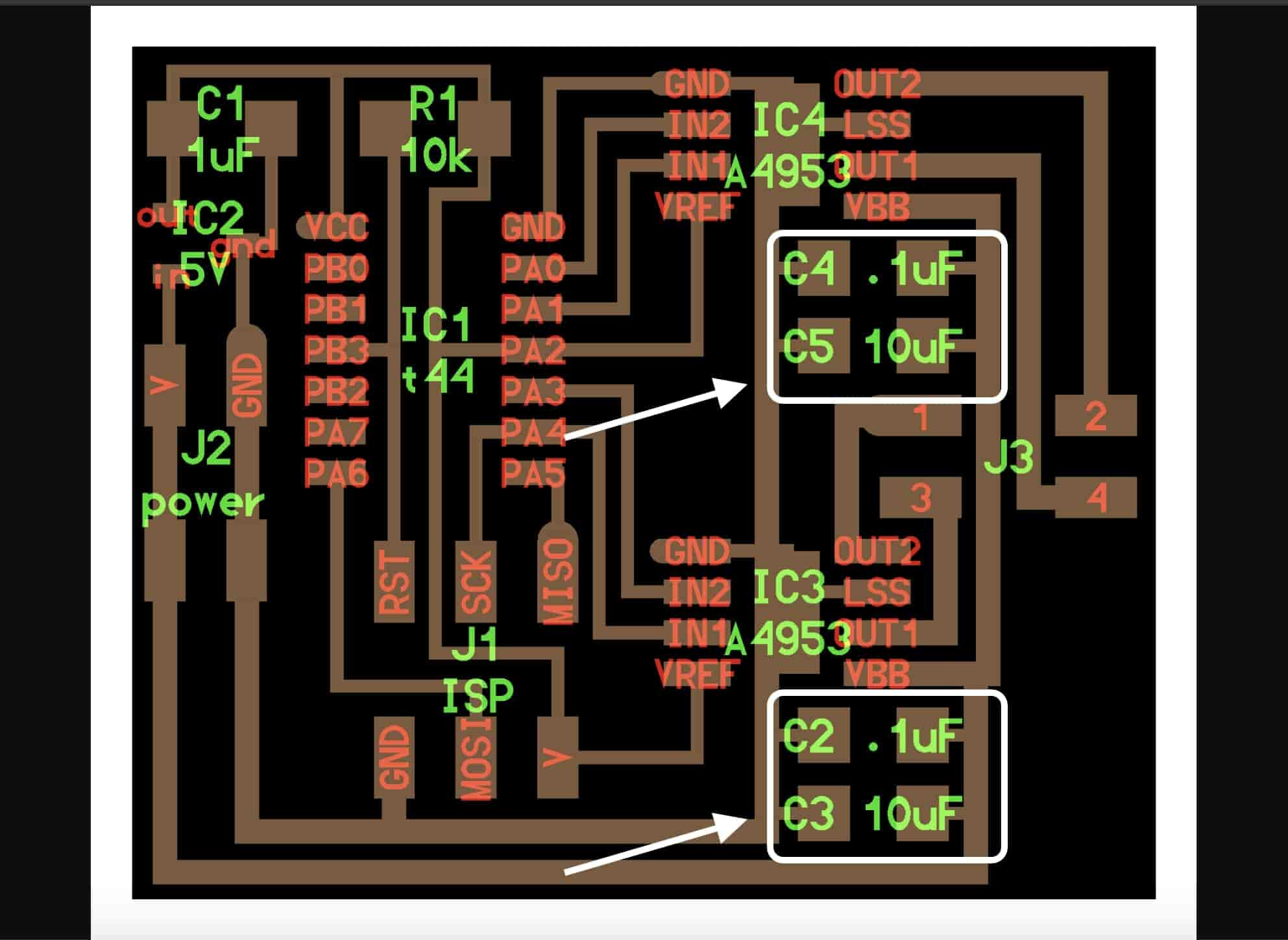
The stepper motor should now step one revolution in one direction and after one second, should step another revolution in the other direction. Now there is a problem! The motor is jiggling and not moving as intended. Although the board is working with the DC motors very well without any problems. I guess the problem is in the capacitors part!
After looking at Prof. Neil’s board and the IC datasheet, I found that each IC should have two decoupling capacitors on the VBB and GND pin separate from each other. But in my circuit I’m connecting only two capacitors for both of them. I guess the problem is here!
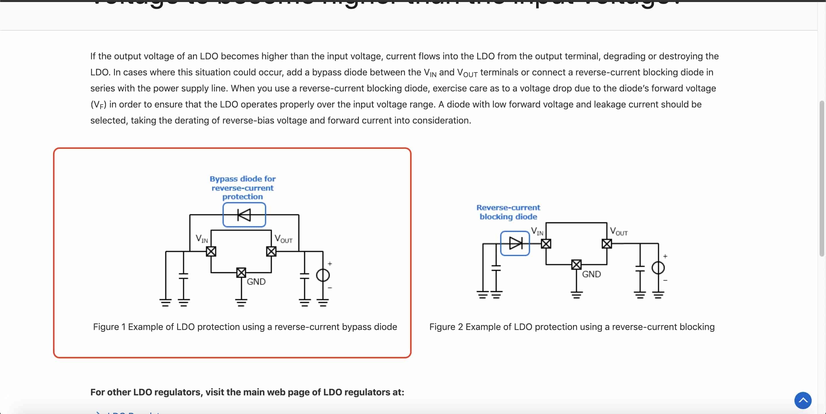
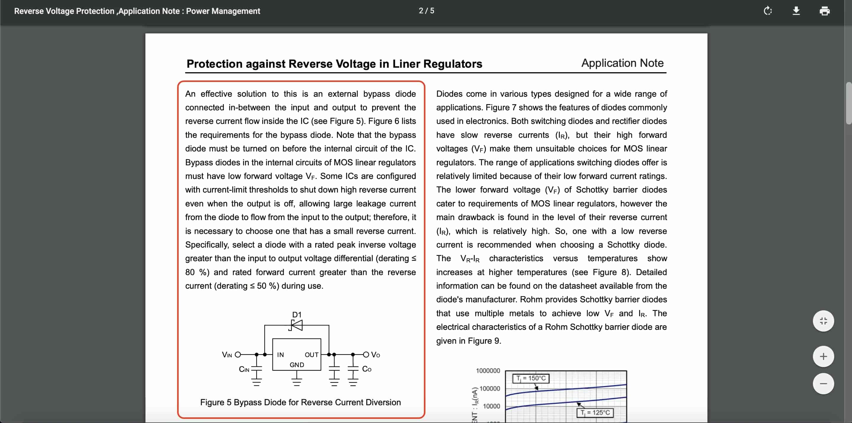
Also, a very annoying problem is that the LM3480 5V in-circuit voltage regulator has no reverse current protection diode. So, when I unplug the 12V battery from the board and connect my programmer to burn my code on the ATtiny44 microcontroller, the LM3480 voltage regulator heats up very very quickly. that’ s because we are injekting 5V from the laptop to the voltage regulator VOUT pin, which causes a reverse current to flow inside the voltage regulator itself. Here’s a good thread mentioning this problem. Thanks Kamel for sharing this link with me. To solve this issue, we need to put a schottky diode in parallel on the voltage regulator.
Another annoying issue is that ATtiny44 microcontroller doesn’t support hardware SPI. Which is a big hassle for me to control the OLED screen over USI. So, I decided to design a new board based on the ATmega328p microcontroller which supports hardware SPI, adding a reverse current protection diode on the voltage regulator, and this time I will use the A4982 Bipolar stepper motor driver to control the stepper motor instead of the A4953 H-bridge IC.
The A4982 stepper driver provides you with a lot of advantages, like it allows you to control bipolar stepper motors in full-,half-,quarter-,and sixteenth-step modes. Also, it has a built-in translator for easy operation, it is the key to the easy implementation of the A4982. Simply, inputting one pulse on the STEP input drives the motor one microstep and can control the motor stepping direction by applying a HIGH or LOW logic value on the driver “DIR” pin.