Input Devices
What’s Going On?
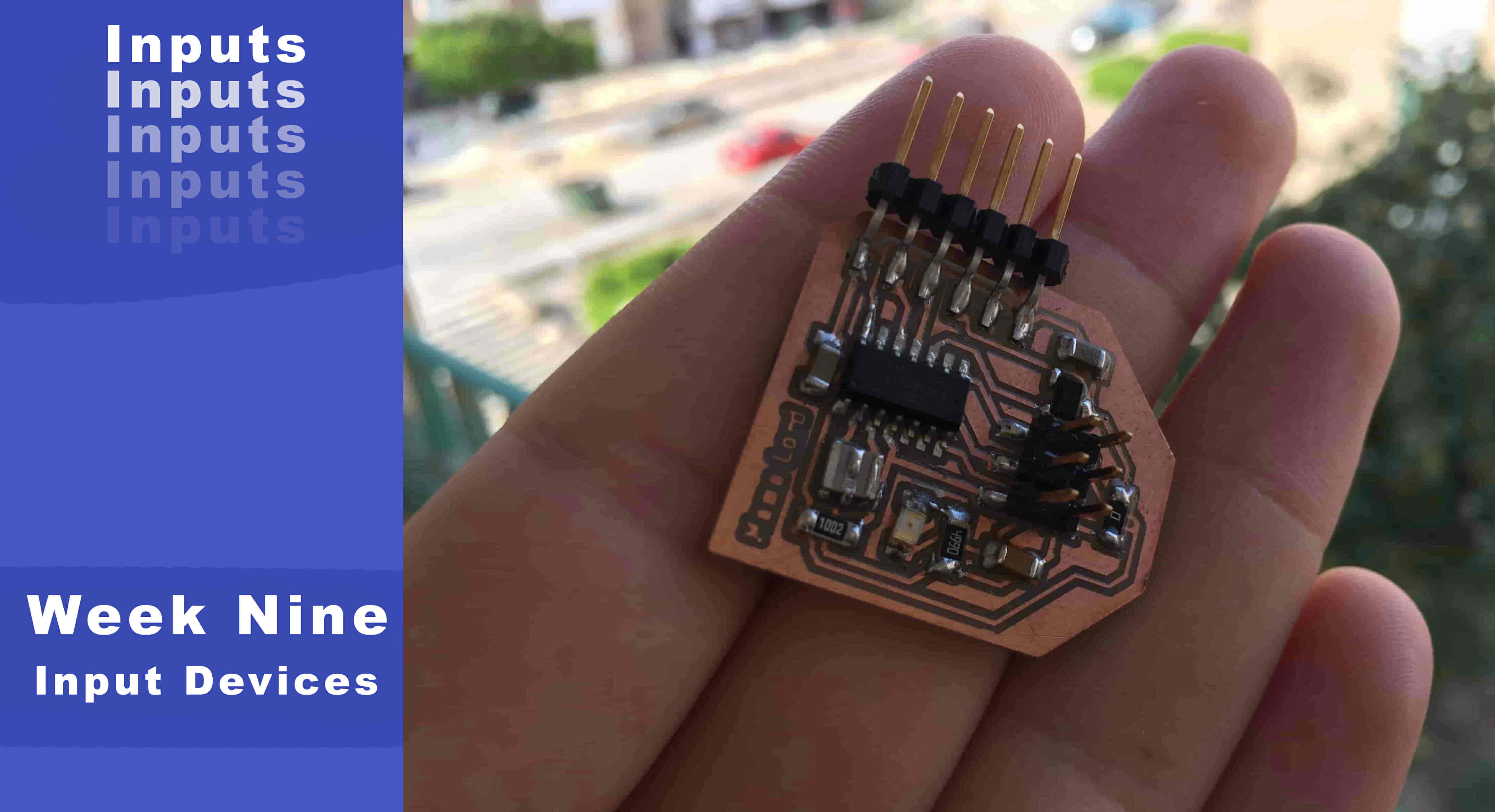
Hello Yall! This week is all about PCBing, that’s the most exciting week for me in the Fab Academy considering that I’m a PCB/electronics design nerd. This week’s assignment is to design a board that has a sensor on it to measure something and read it.
After reviewing the global lecture and going through the sensors that Prof. Neil talked about, I like the Mems MIC and the Hall effect sensor. It’s my first time to know about the MEMS MIC and that it doesn’t need an external amplifier circuit. Since I have some bad memories with amplifiers I decided to build my first board with that MEMS MIC and see how it will work.
I built about 4-5 boards based on the ATtiny44 microcontroller. So, this week’s assignment I thought about building my board based on the ATmega328p microcontroller. That will help me a lot in my final project too since it will be ATmega328p based. I thought too on putting the two sensors(MIC, Hall Effect) on the same board along with FTDI or CH340 IC to convert from USB to serial communication, and putting some GPIO pin headers to allow anyone to access the remaining and not used microcontroller I/O pins. It’s kinda a not small board but as I stated before this will help me a lot with practicing for my final project.
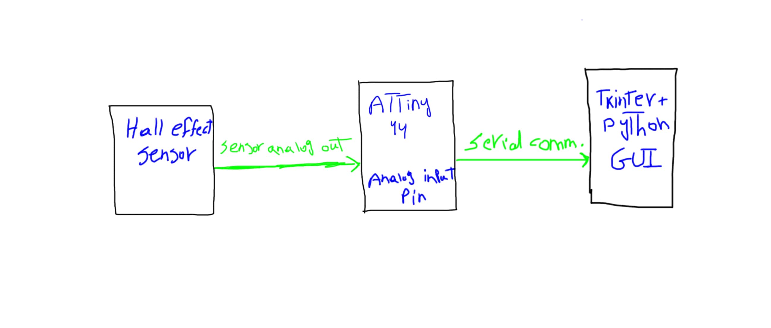
Start with sketching your project concept on a piece of paper is always a good idea.
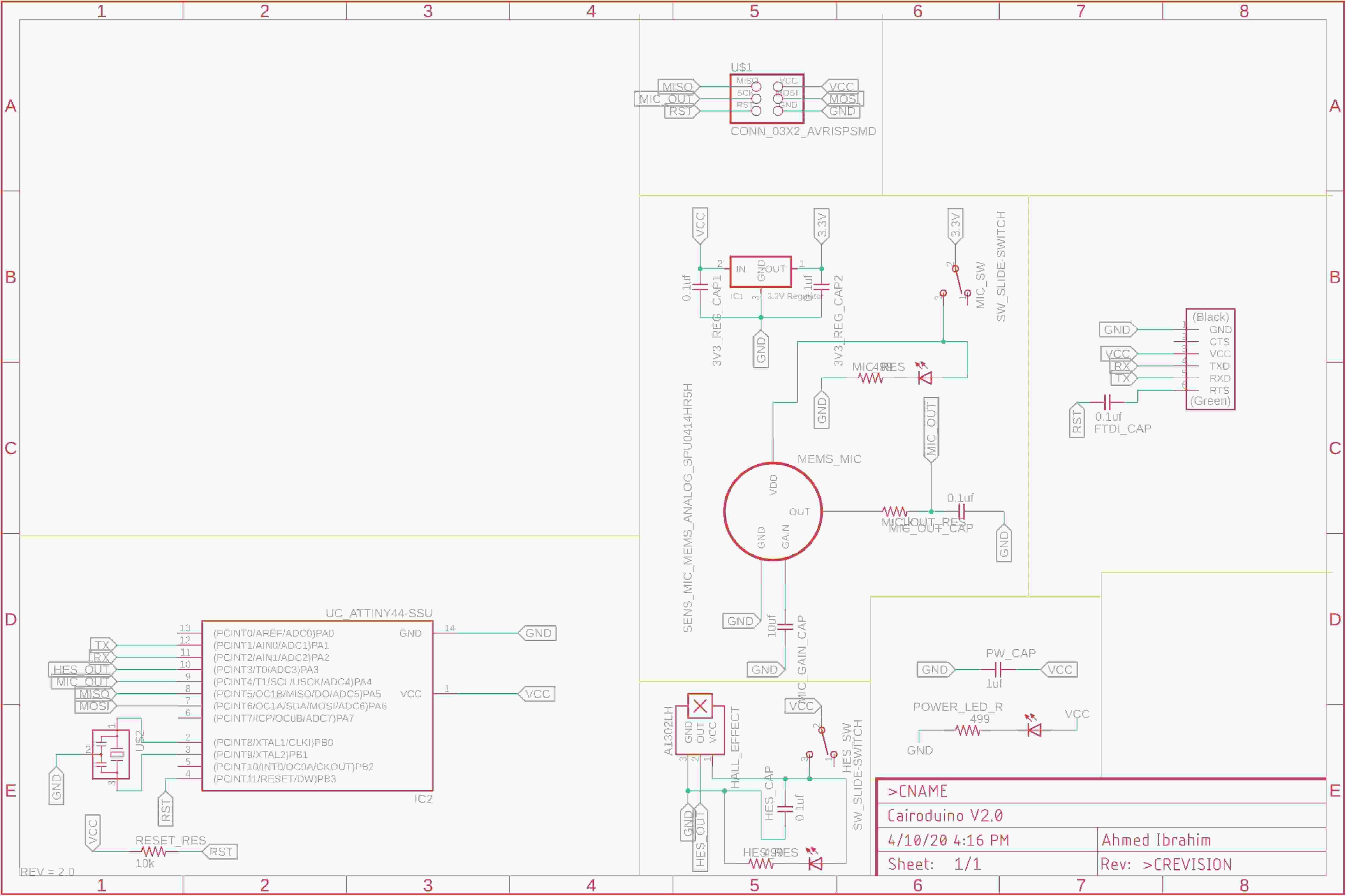
Then I opened Eagle and started working on the circuit schematic, The board is based on the ATmega328p microcontroller, it has a built-in USB to Serial converter circuit, GPIO breakout pin headers, Built-in MIC & Hall Effect sensor, and onboard 5V & 3.3V regulators
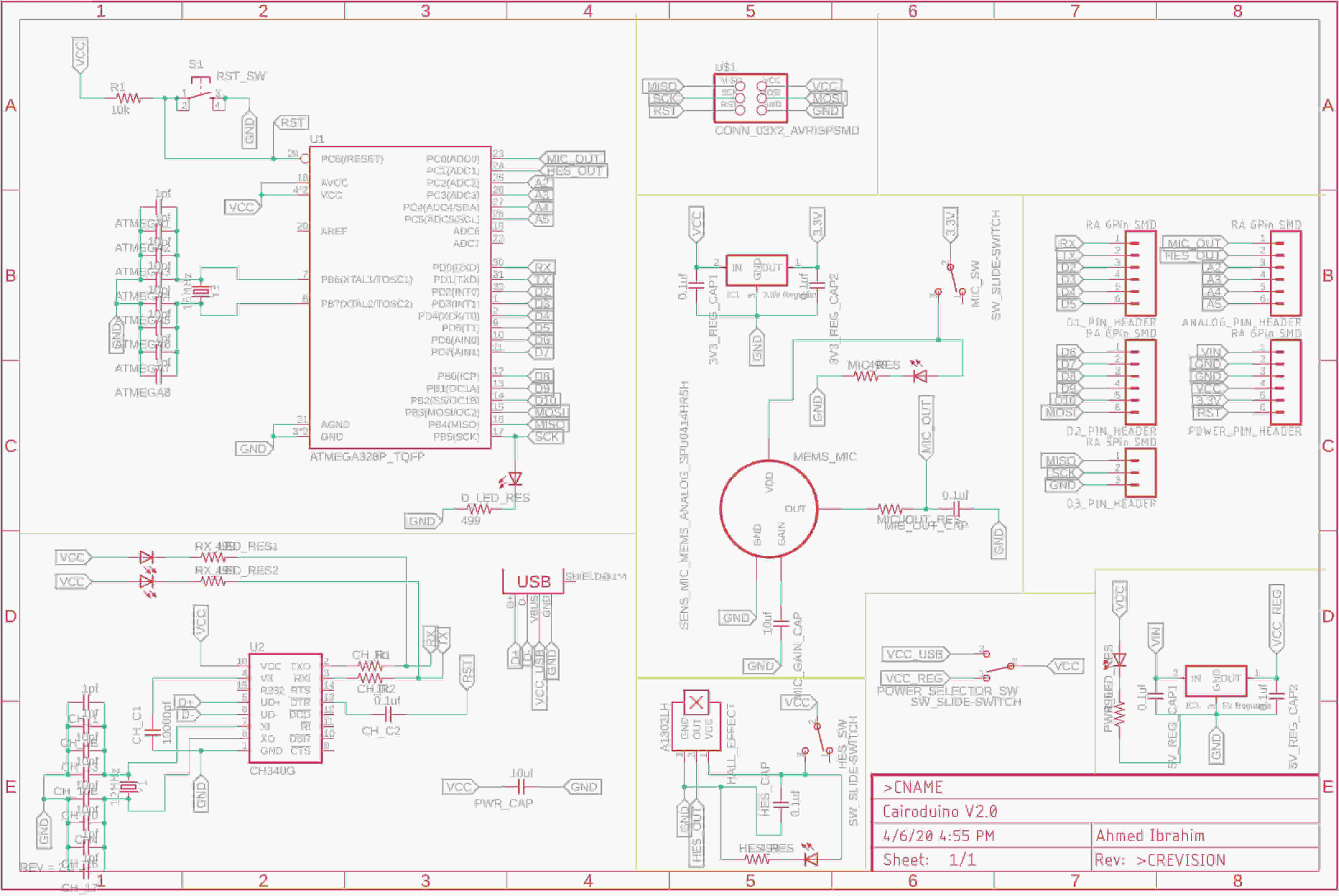
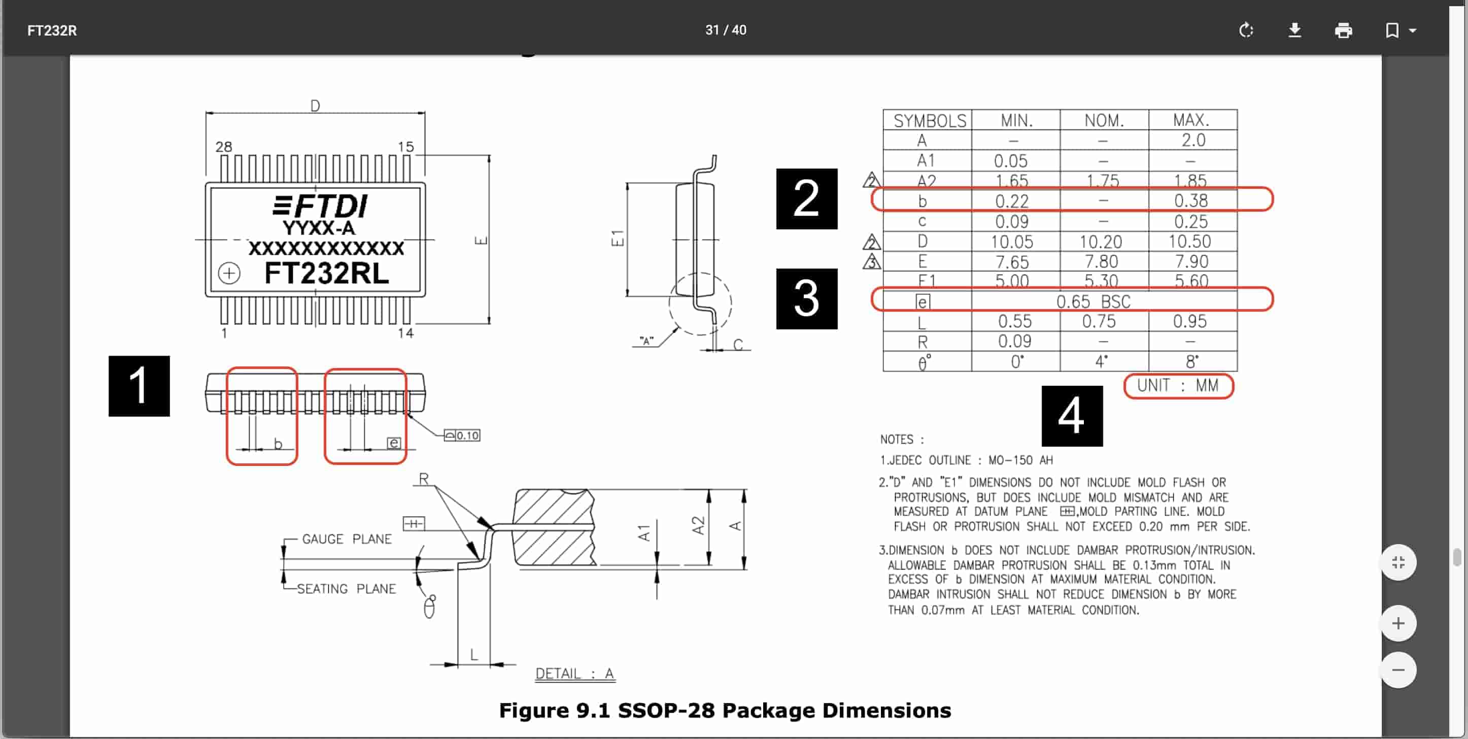
To convert from USB to Serial, I used the CH340G IC because it’s easier to soldier, also it’s easier for the machine to cut its traces since the FTDI(it’s alternative) pins pitch is so small and we don’t have an endmill that capable to give that very small clearance.
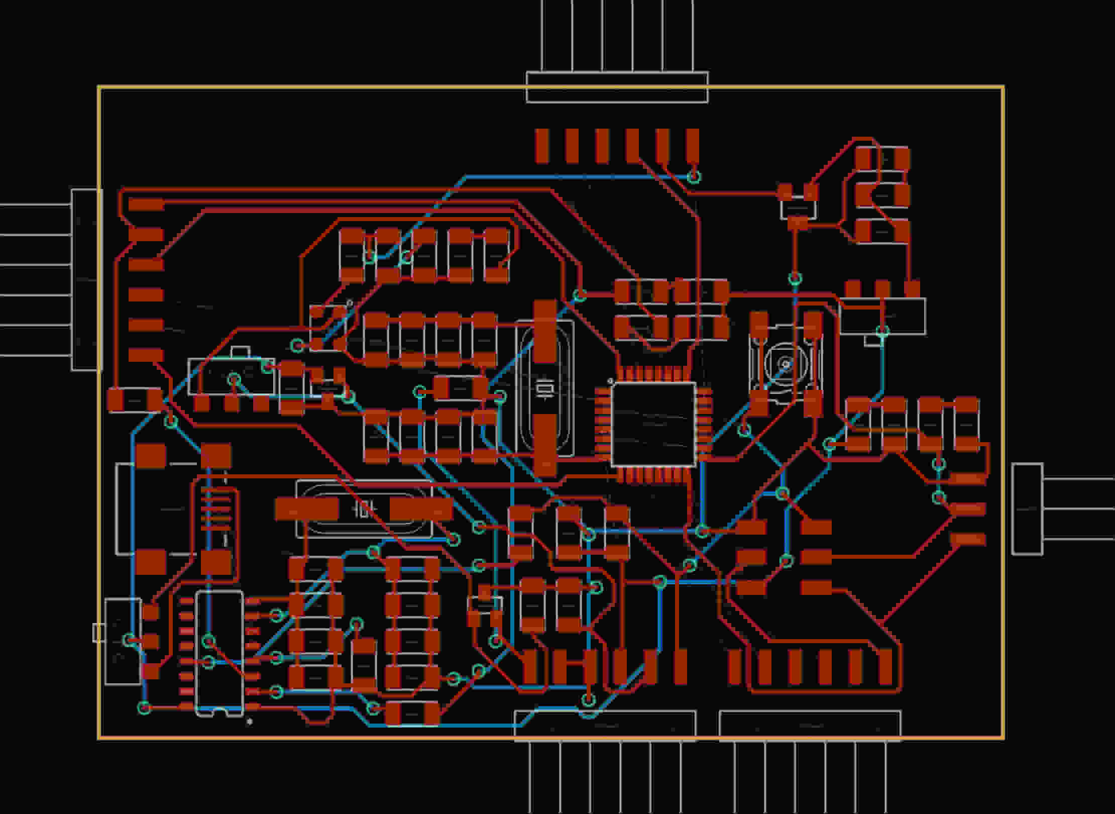
After finishing the circuit schematic, I converted into the board layout, that’s the sad part! I tried a lot to route the tracks on a single side or double sides but I didn’t’ succeed. I don’t know if The board is big or my components placement on the board layout is not good enough. But anyway, I attached the board source files if you want to give it a shoot and try to route it.
PCB Source Files Download
At this point, I decided to make another version of it. it’s smaller now. I removed all the unnecessary components like the USB, CH340G, some of the pins breakout headers, switches, and the LEDs. and replaced the ATmega328p with the ATtiny44. It now only has the two sensors(MIC, Hall Effect) and the bare minimum configuration of the ATtiny44 microcontroller.
I succeded this time to route the board on the two sides(Top & Bottom), I never fabricated a two-sided PCB before it will be challenging, but I love challenges.
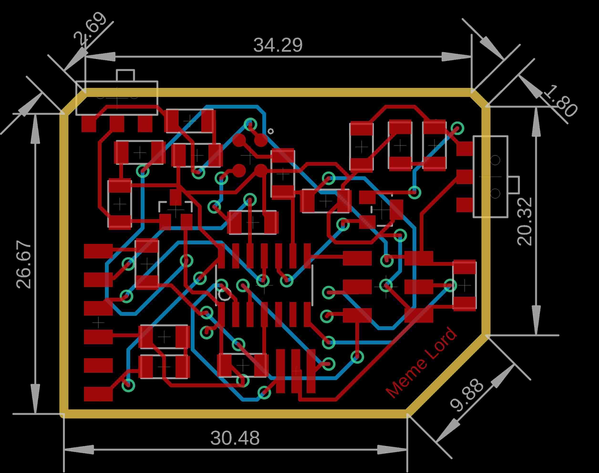
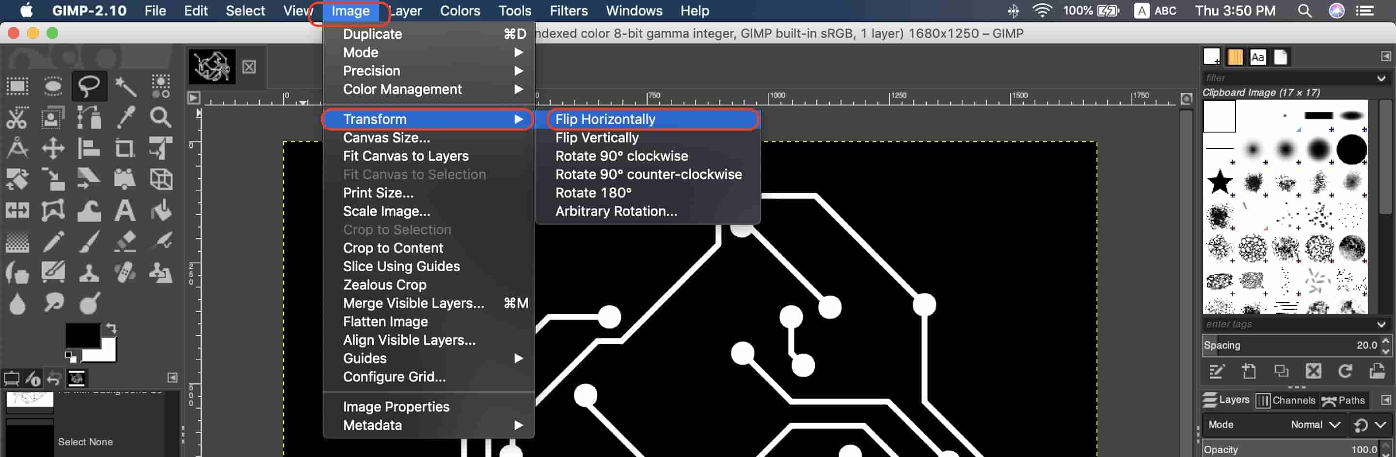
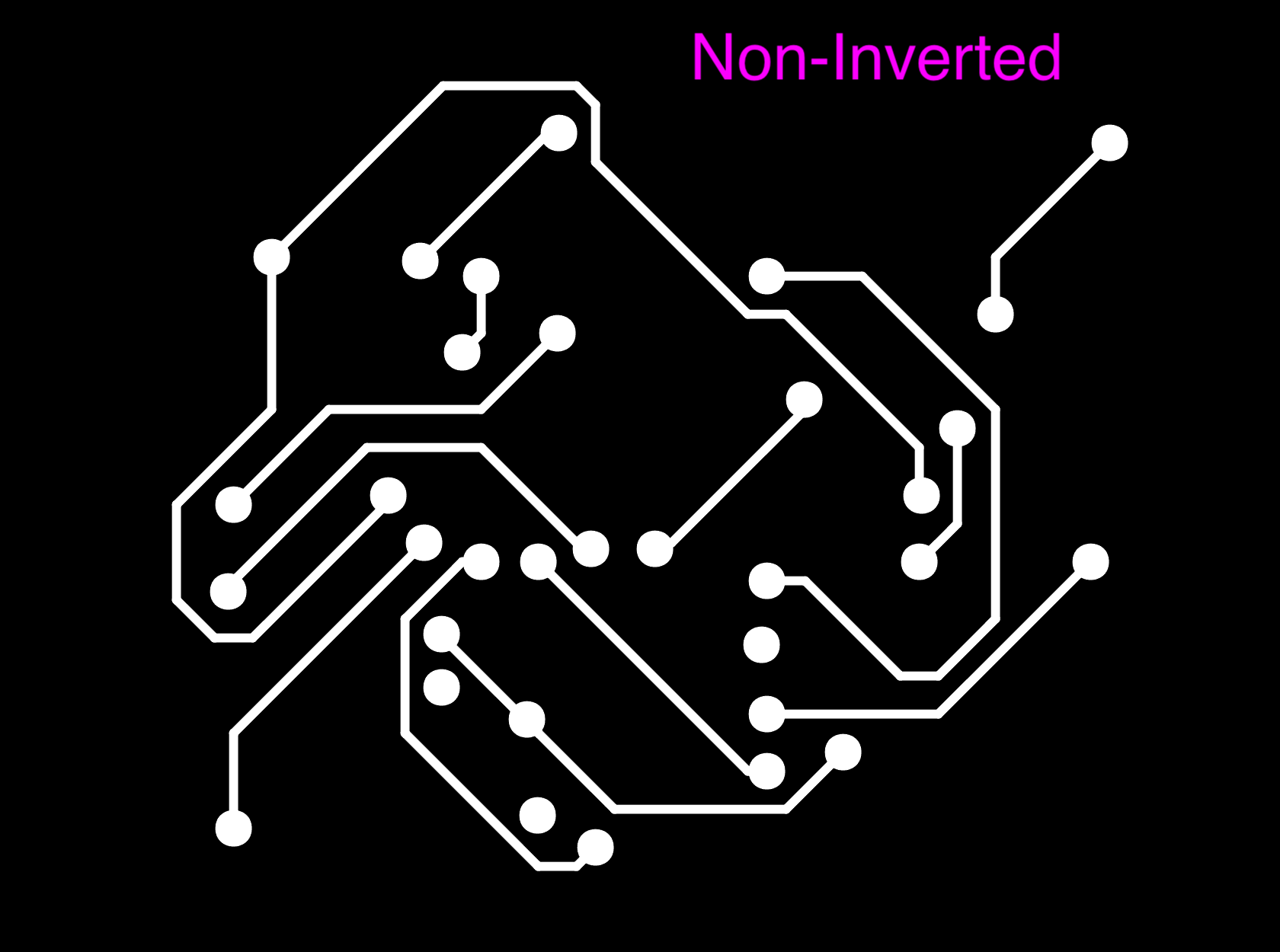
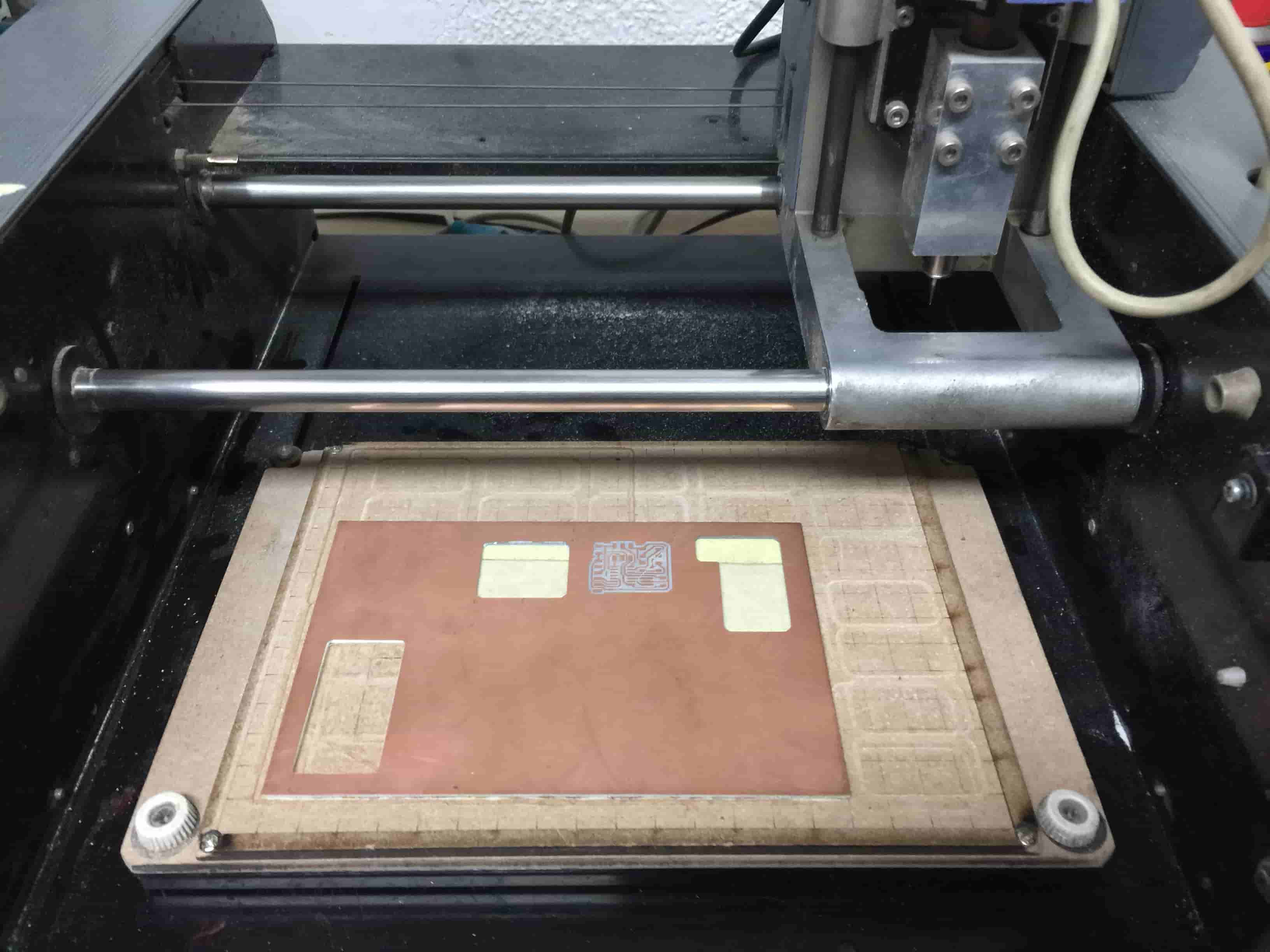
After going to the Lab and installing the PCB on the machine bed, I exported some PNG files, one for the top traces, bottom traces, drills, outline. When fabricating a double-sided PBC it’s very important to mirror the bottom traces image to align it correctly with the top side when you flip the board on the machine bed.

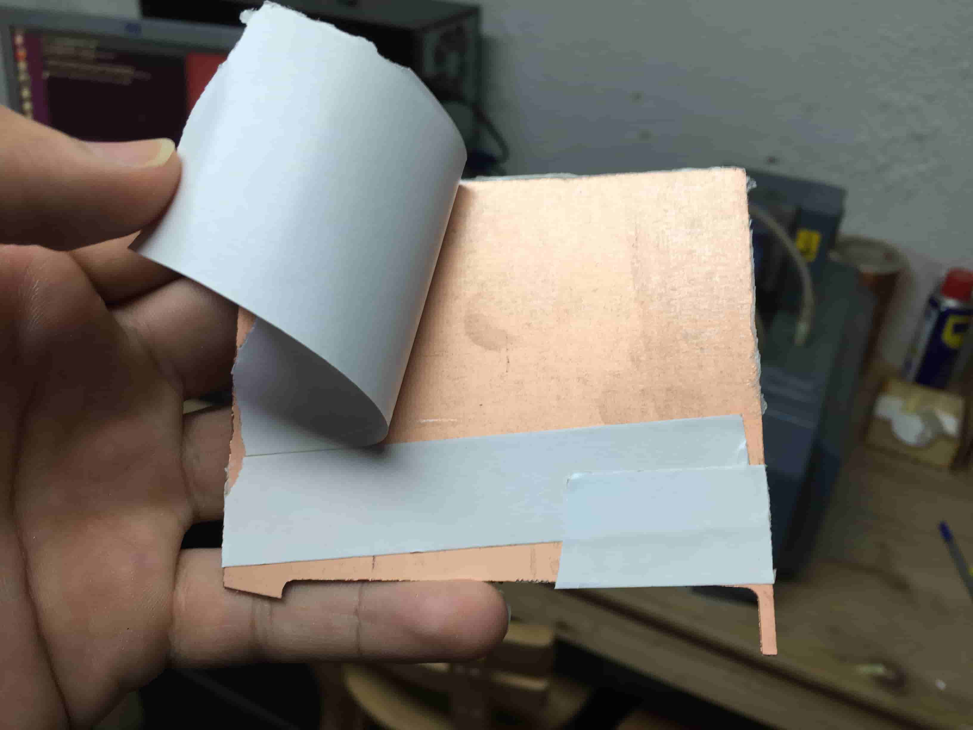
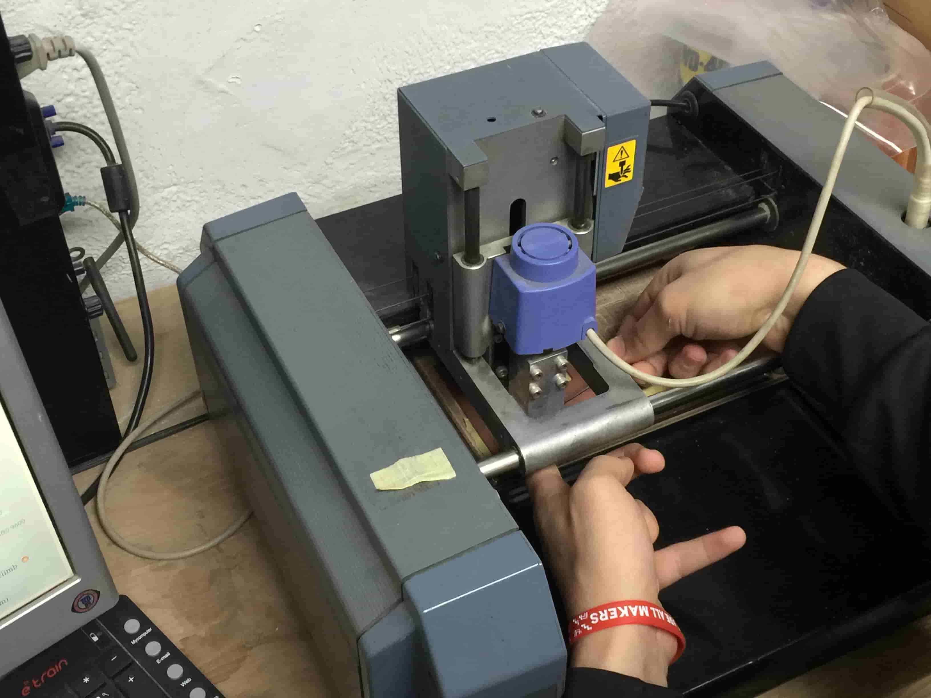
While installing the PCB on your machine bed it's very important to make sure that the bed is very clean to make the PCB flat on the bed as possible to not break your endmill.
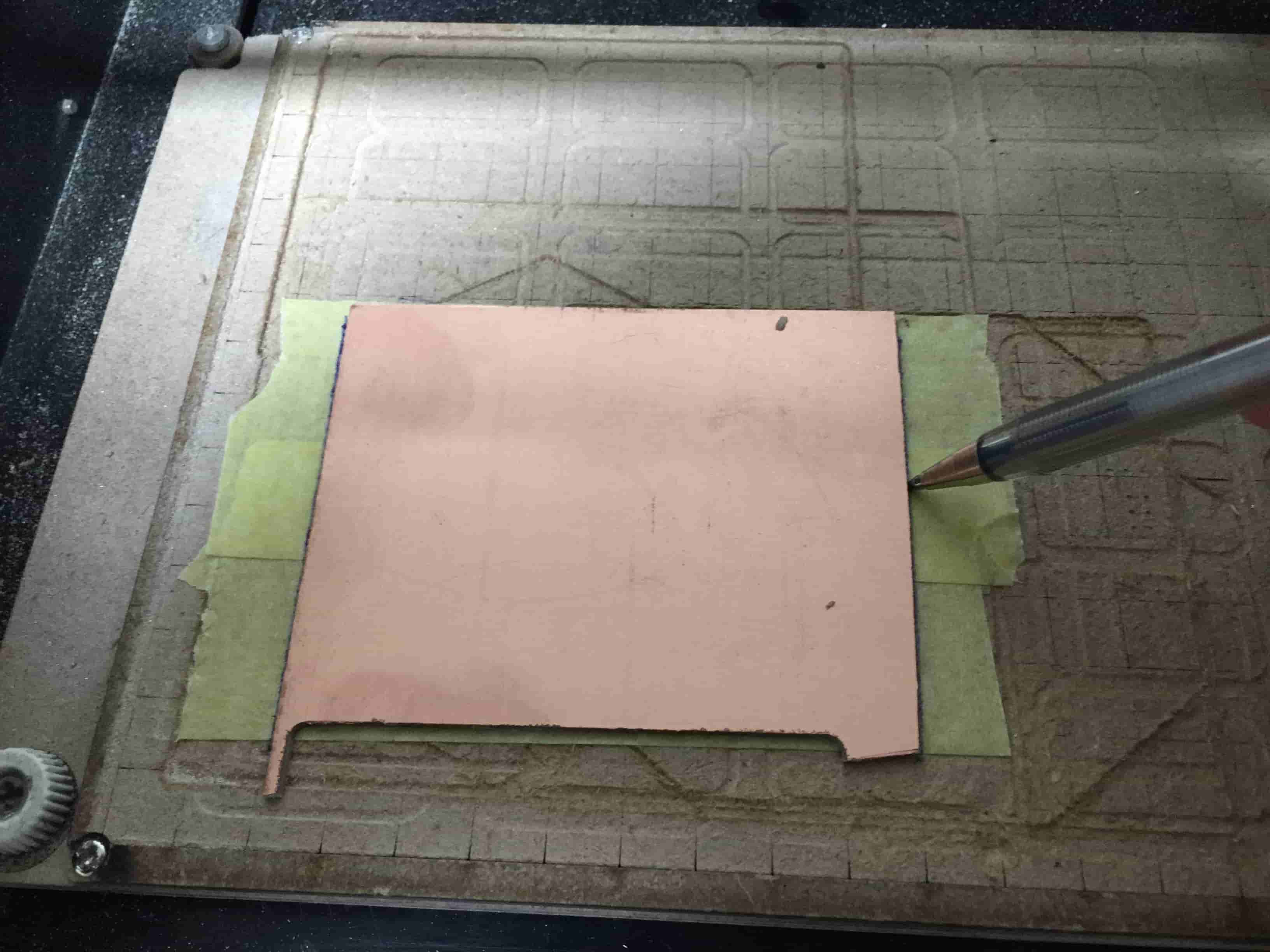
Now, import them to Fab Modules, start calculating the toolpath then send it to the machine to start working. More details about this part in Electronics Design Week and Electronics Production week
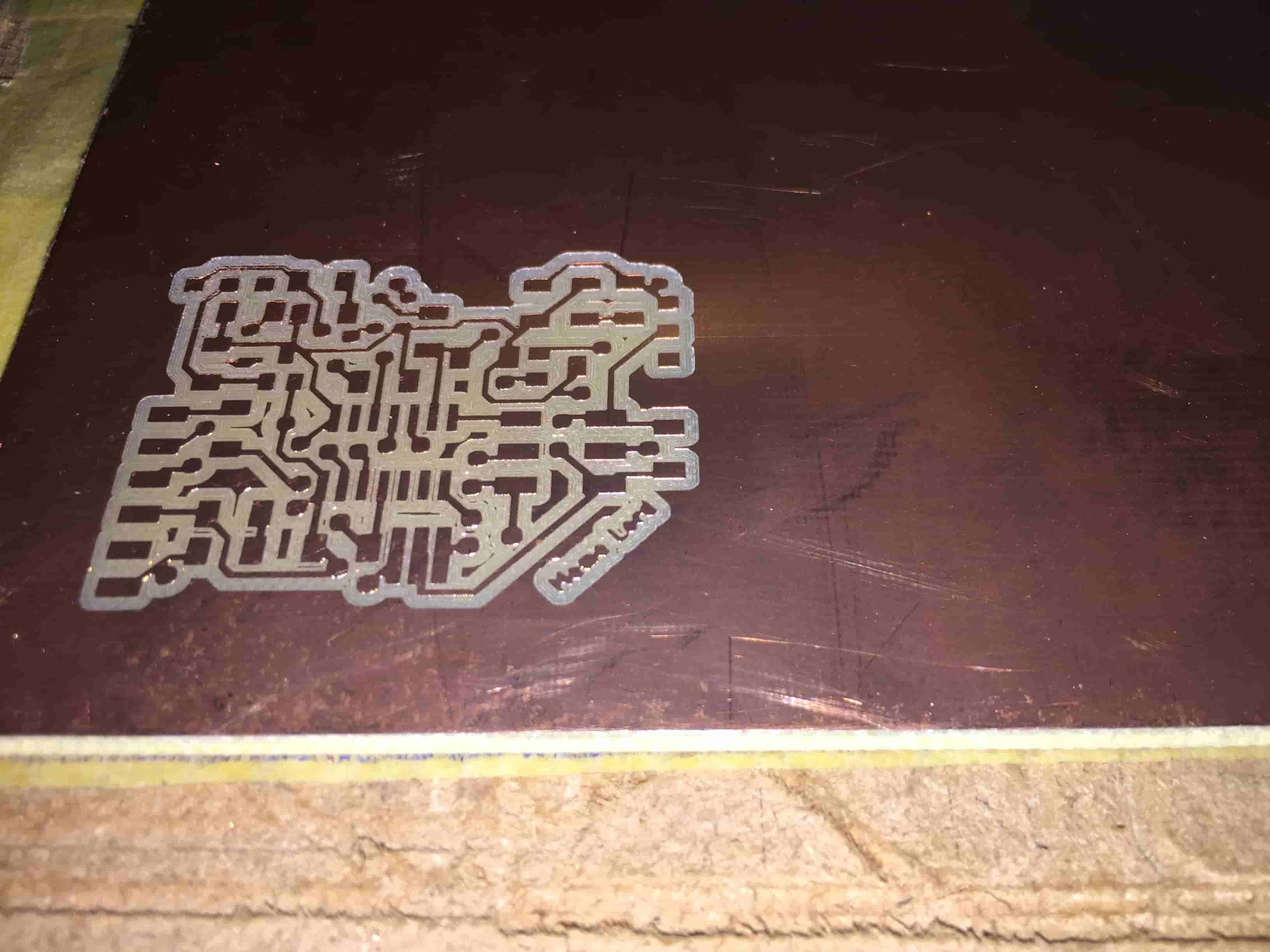
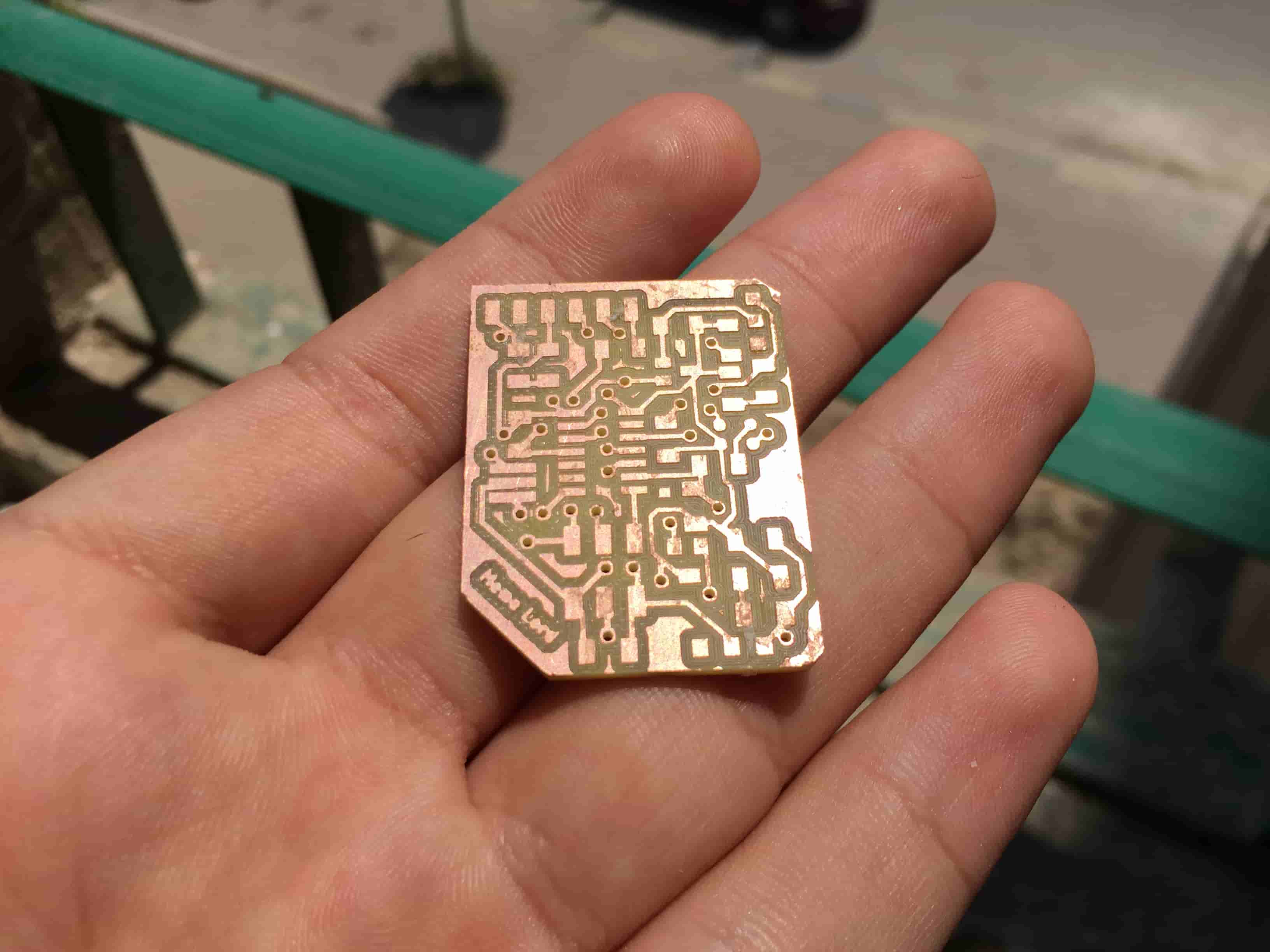
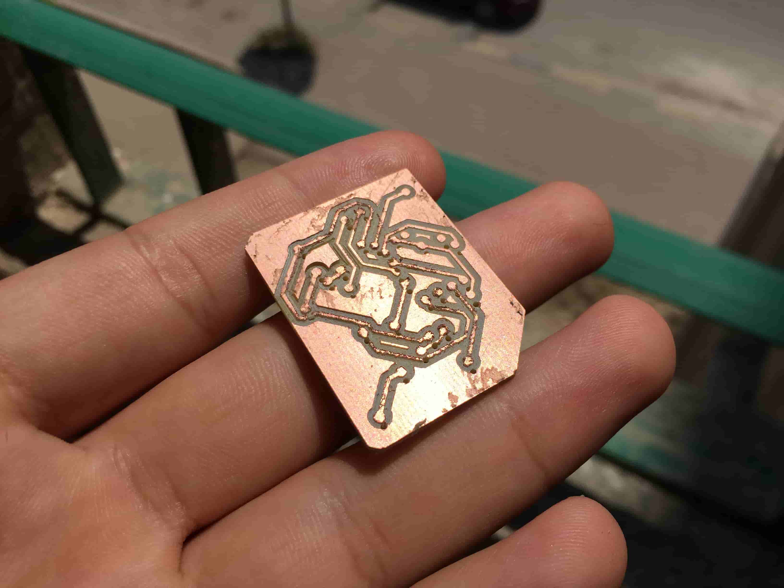
The Top layer traces went great and no problems at all. Then I made the vias drills and it went great too
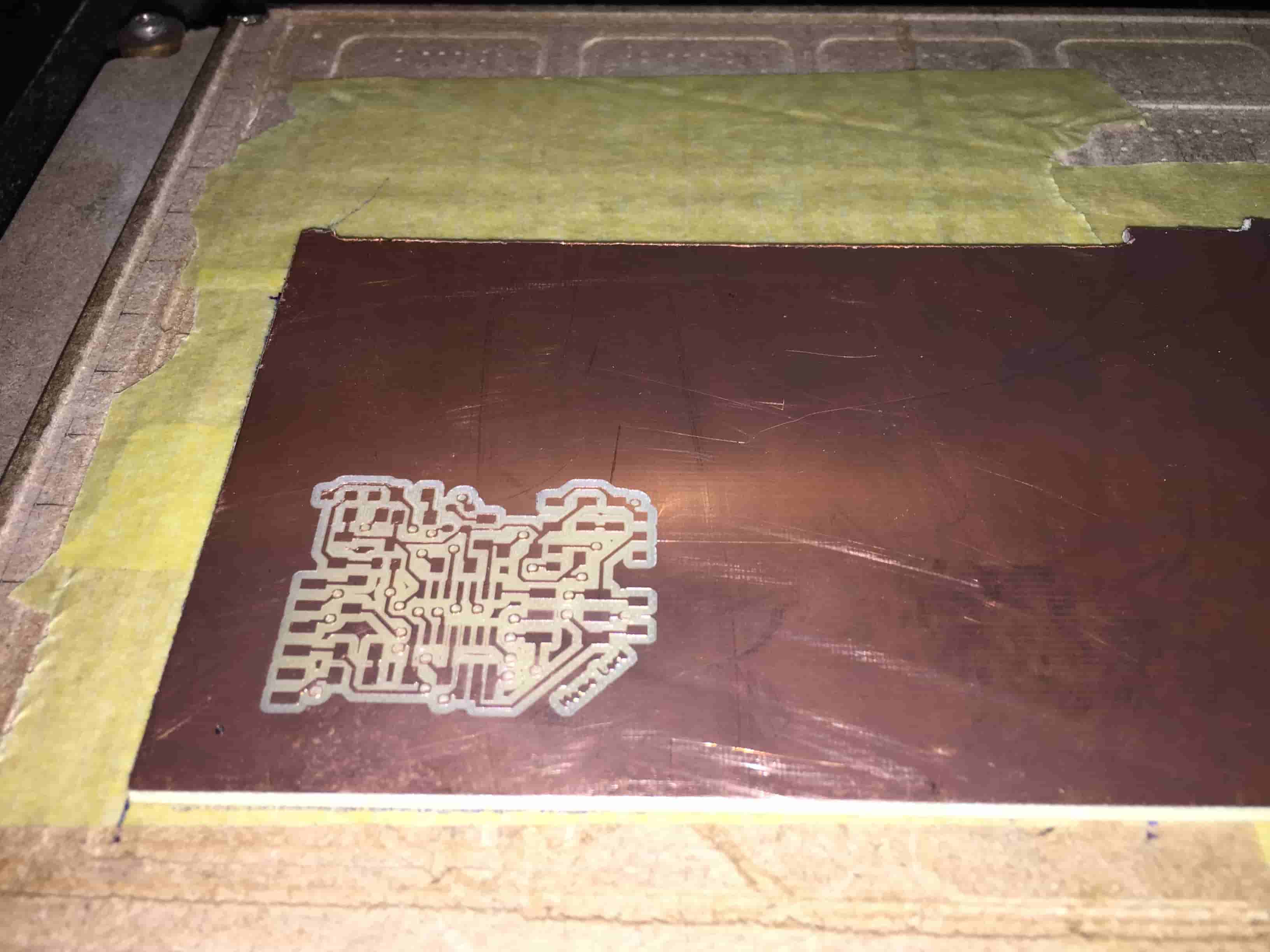
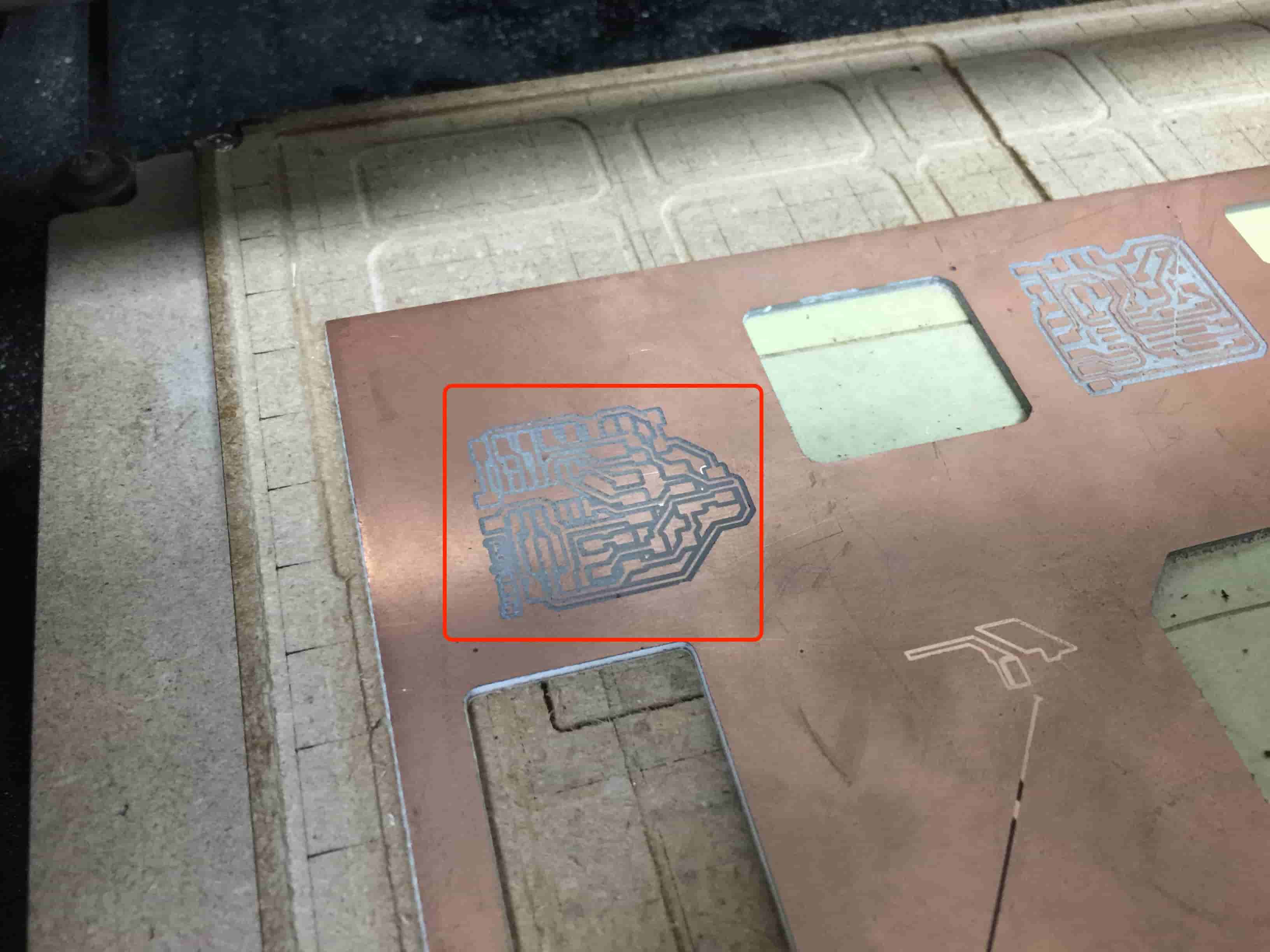
After I flipped the PCB on the machine bed to make the bottom traces, I tried to put it on the same previous position but it seems that I wasn’t accurate enough. A shift in the X-axis happened. And here is the results.
Since I don’t have the time to remake that board again because here is a curfew in Egypt can’t stay longer in the Lab. I returned back home and redesigned two new boards, one has the MIC and the other one has the Hall Effect sensor on it.
Let’s talk about the details of how I designed these two new boards.
Getting Familiar with the Hall Effect sensor
Basically, the Hall effect sensor’s main purpose is to measure the magnitude of the magnetic field near it. We can use this sensor in many applications, like proximity sensing, positioning, speed detection, and current sensing applications. Hall effect sensors are activated by a magnetic field and in many applications the device can be operated by a single permanent magnet attached to a moving shaft or device. Actually, I found it’s an interesting sensor that’s why I chose to use it on my board. For more details on how this thing works check this out.
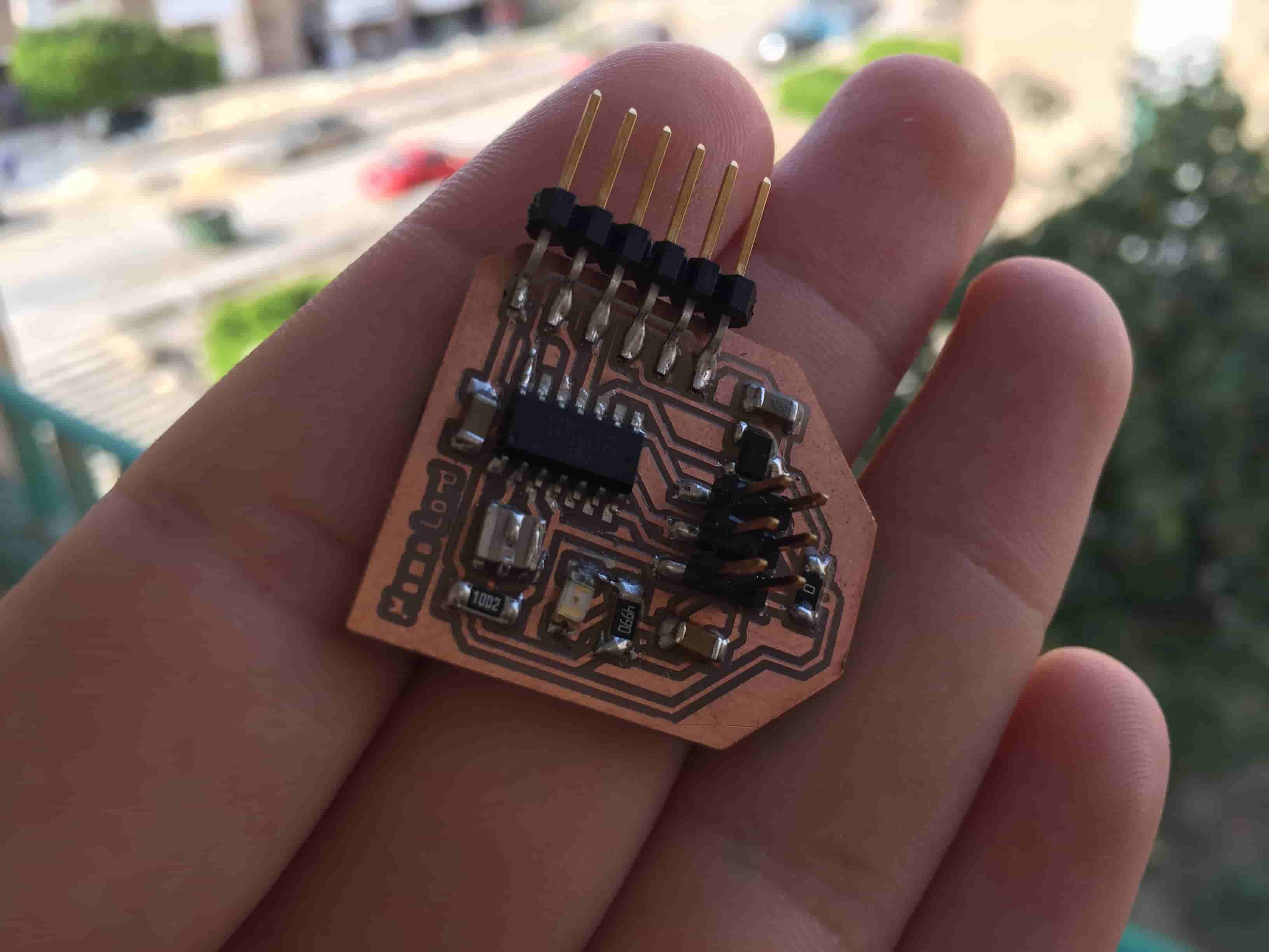
The hall effect sensor that we will use today is the A1324LLHLT-T it’s a SOT23W package sensor. It has three pins(VCC, GND, and Vout). It’s pretty easy to use.
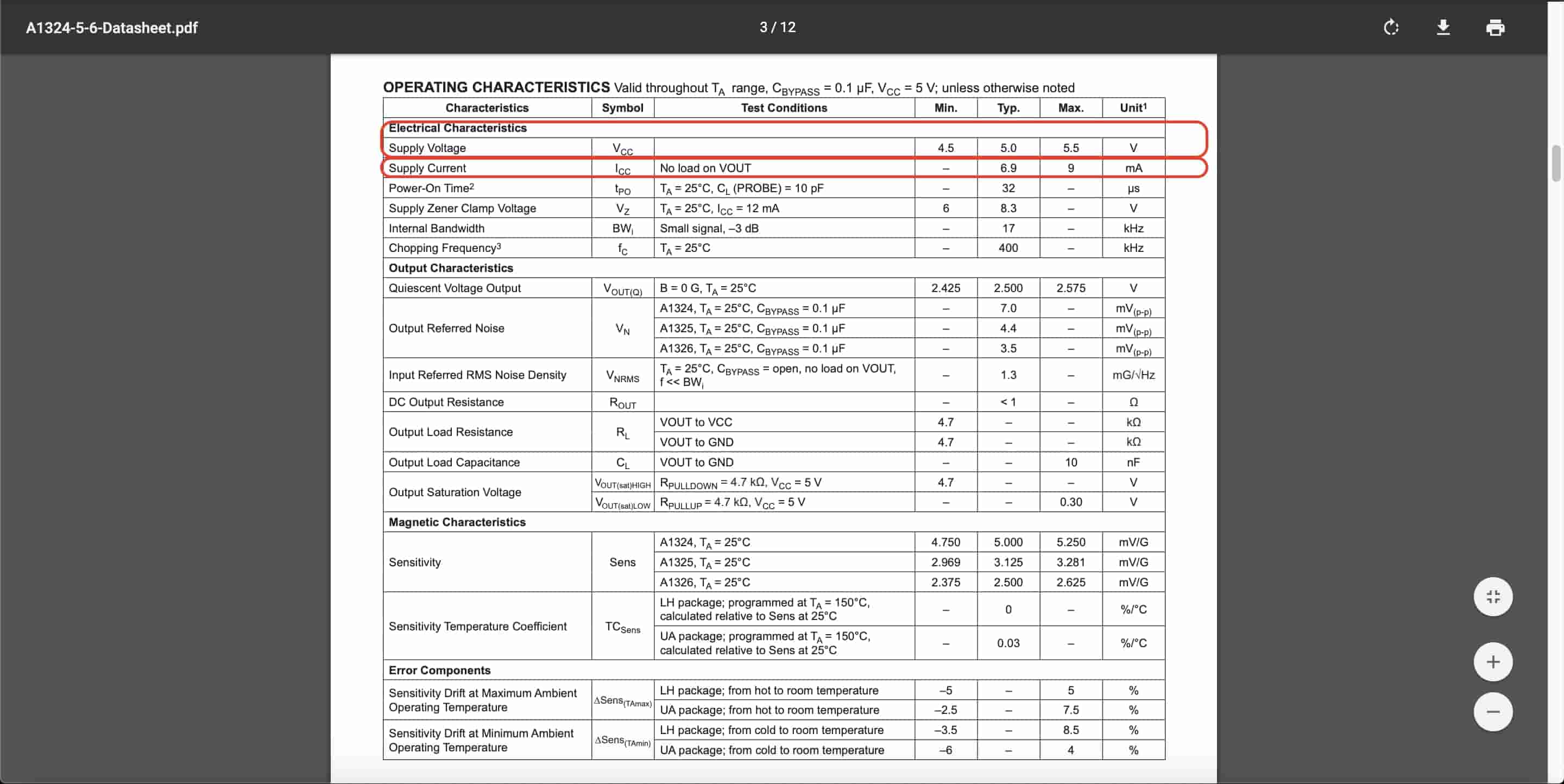
I never used this sensor before, before doing any kind of circuit designing I need some more information on this sensor pinout, what is the recommended supply voltage, ...etc.
The best place to get all of this information is to open this component datasheet. We found that the supply voltage(absolute maximum rating) is 8V. But please notice that it’s not recommended at all to design your circuit upon the absolute maximum rating. Also, we got the pinout of the sensor. The recommended supply voltage is from 4.5V to 5.5V
Also in the datasheet, we can find the typical application circuit of the sensor and some recommendations on how to wire it. It’s recommended to put a 0.1uf bypass capacitor on the VCC and GND of the sensor for filtration purposes.
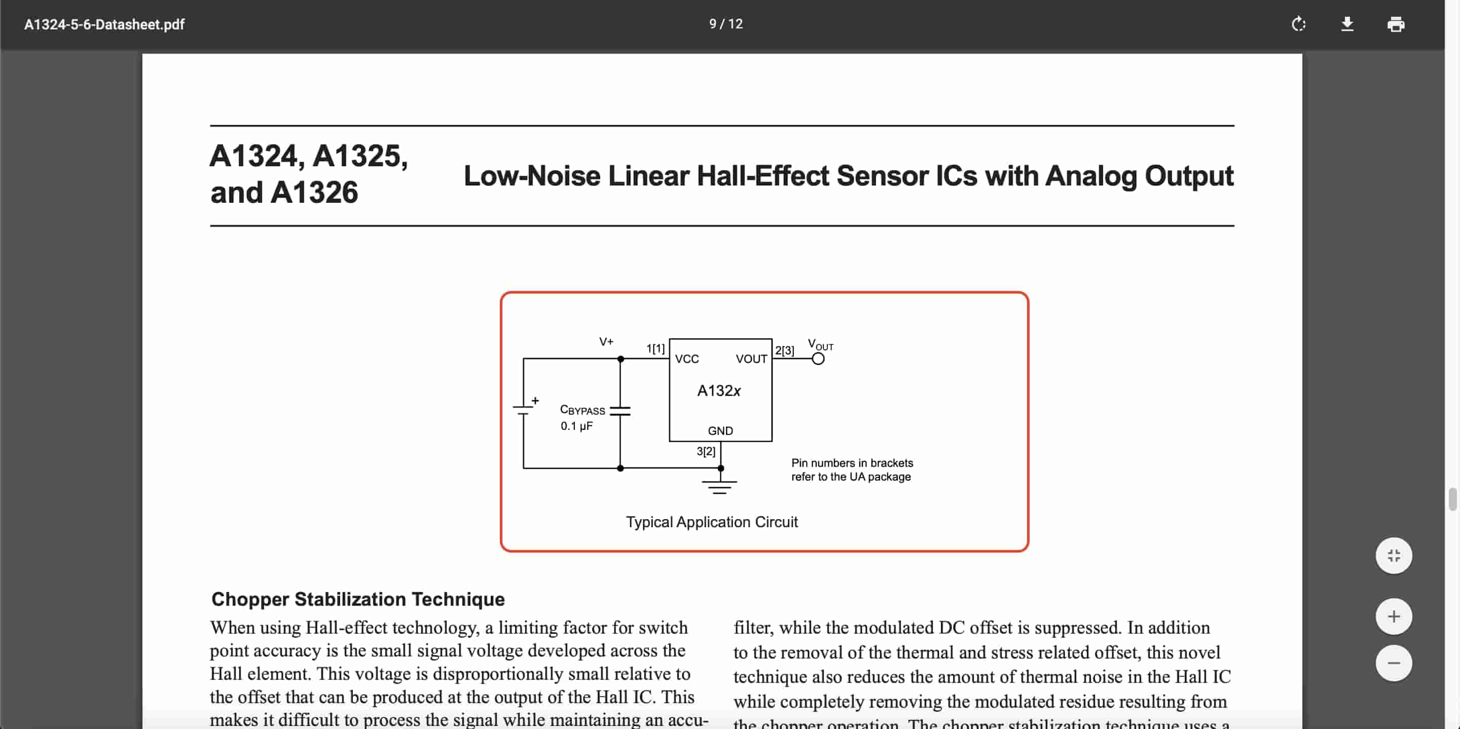
We should connect The sensor output pin to an analog input pin on the ATtinny44 microcontroller to be able to read the sensor data so we can display it on the serial monitor later on.
Hall Effect Sensor Board Design
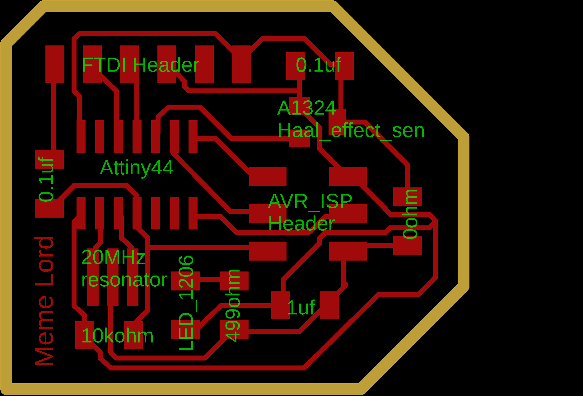
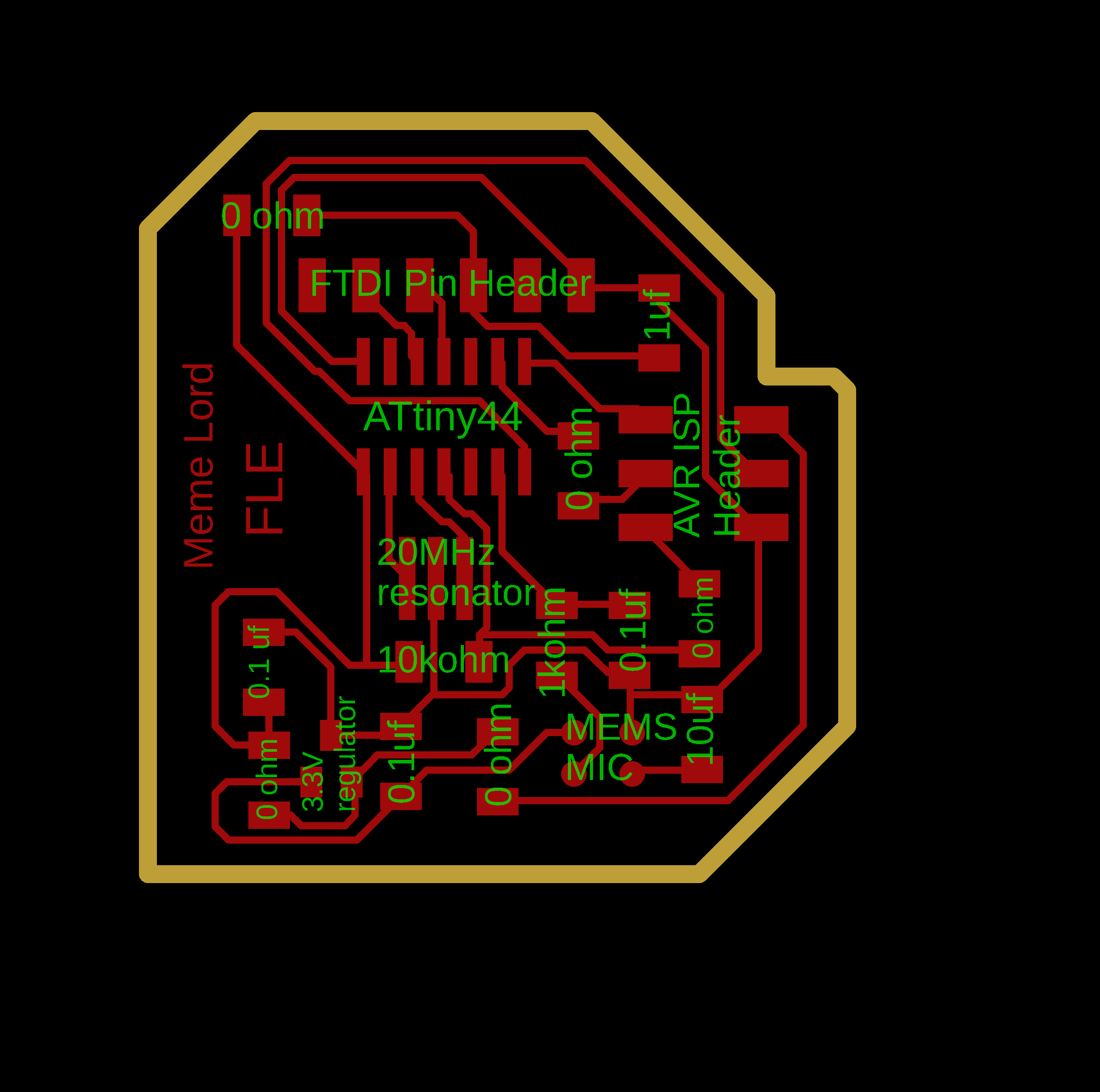
I started designing my circuit on Eagle, I placed all the components that I need to use in my circuit like the ATtinny44, hall effect sensor, resistors, capacitors, ...etc. Then I started to connect things together.
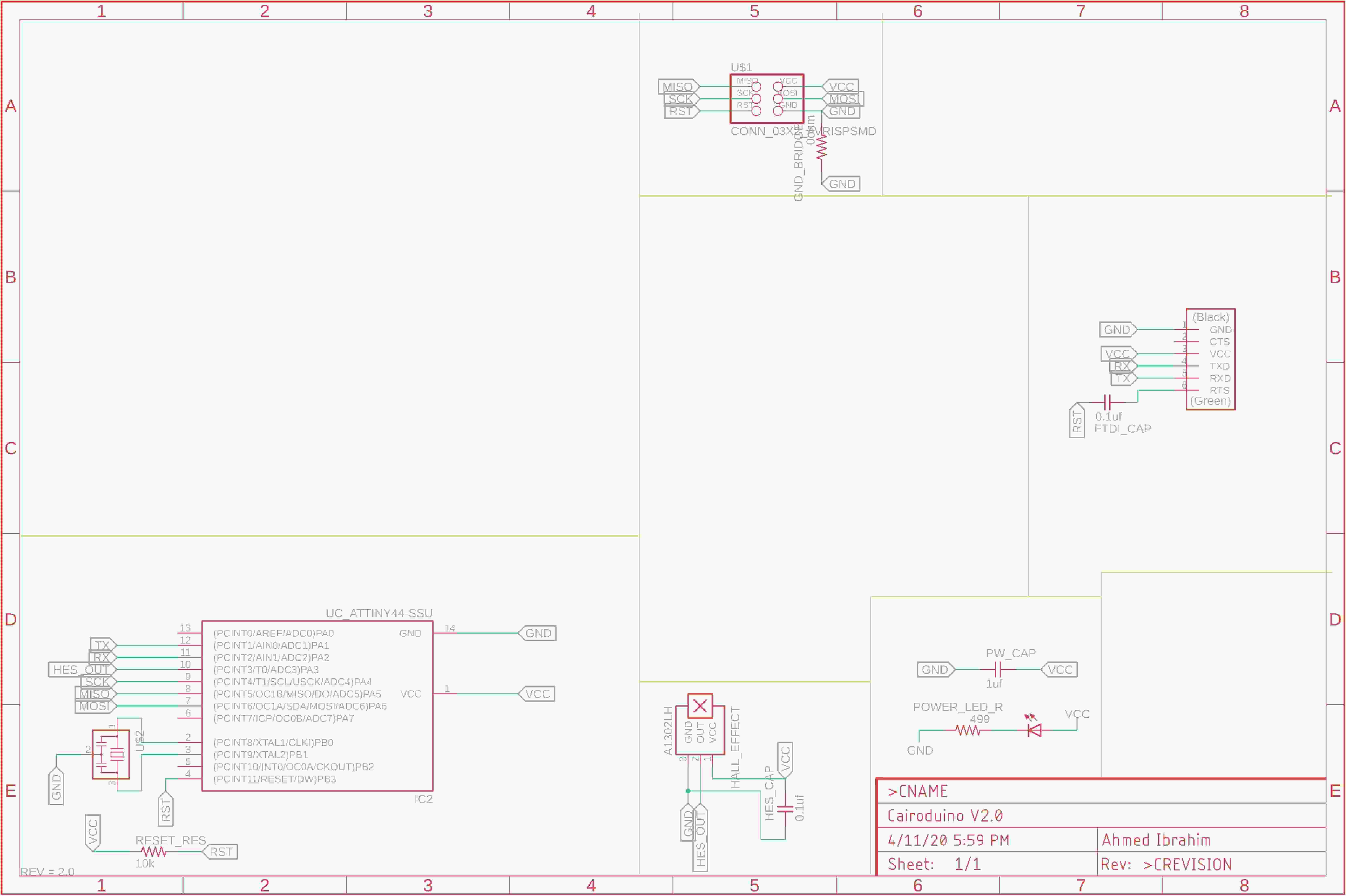
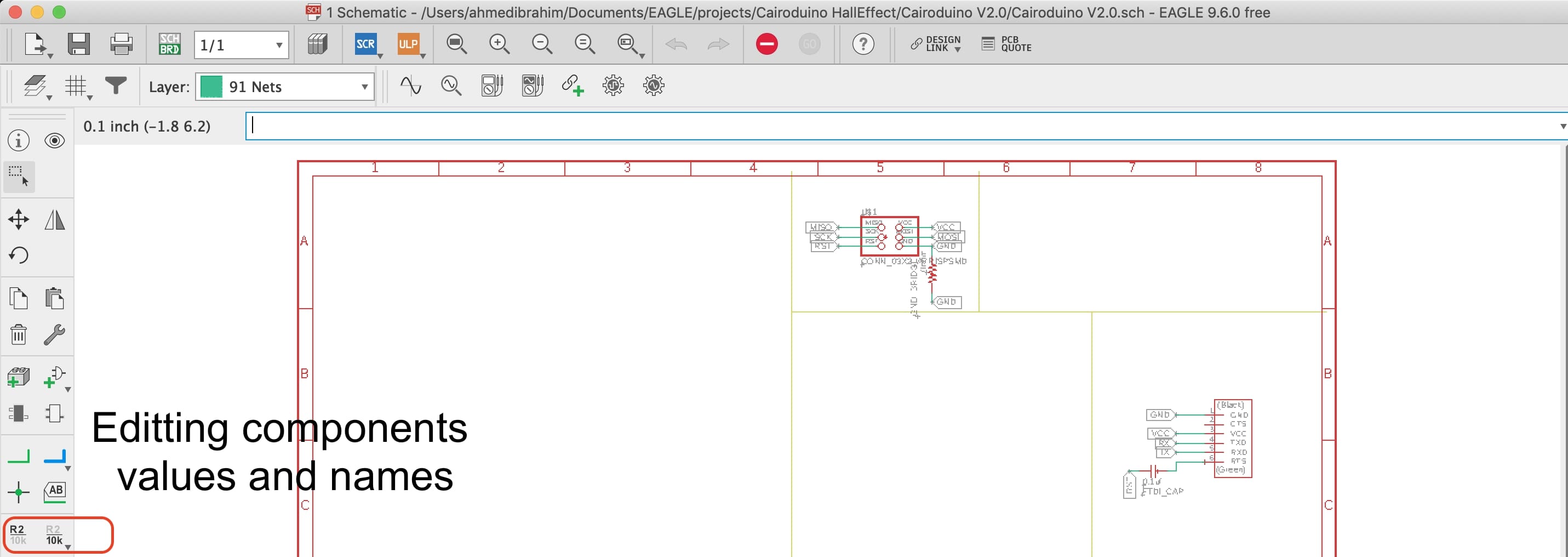
I like to give all the components names and it’s real values, it makes placing the components in the real world later easier for me.
After finishing the schematic, it’s time to lay out all the footprints on the board. Take this advice from your dude, take your time on placing the components on the board, if the placement of your components is not good enough the routing process will be a nightmare. So, again take your time in placing the components.
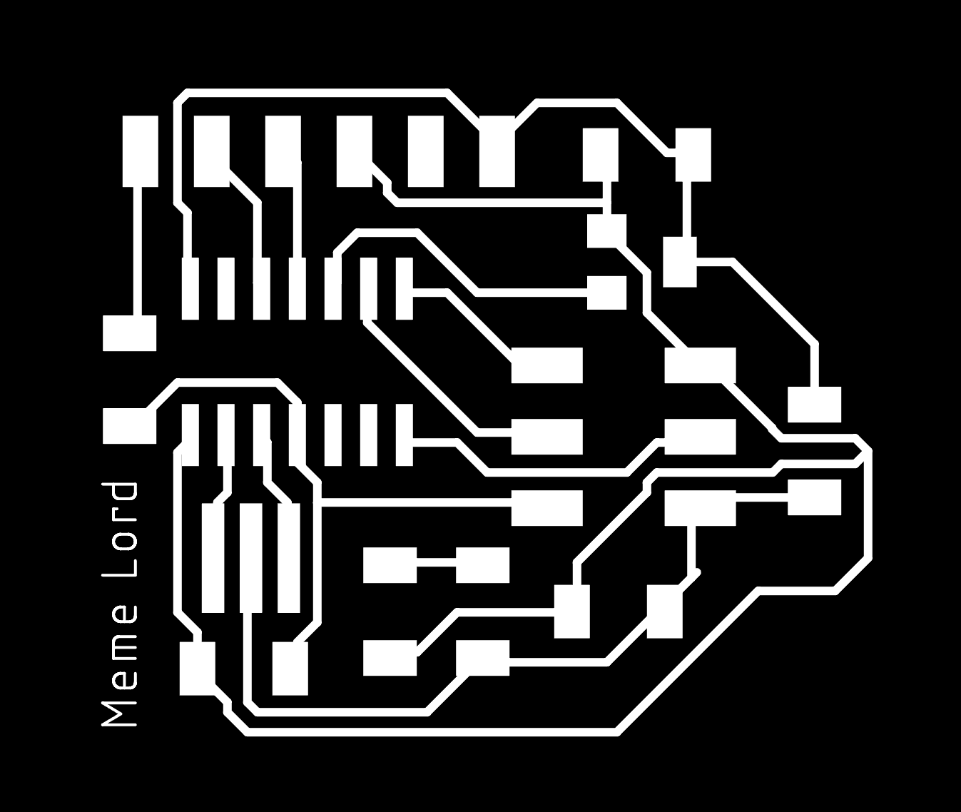
After I placed the components on the board I started routing the air wires. For more information on the PCB design part, please check Electronics Design Week’s assignment.

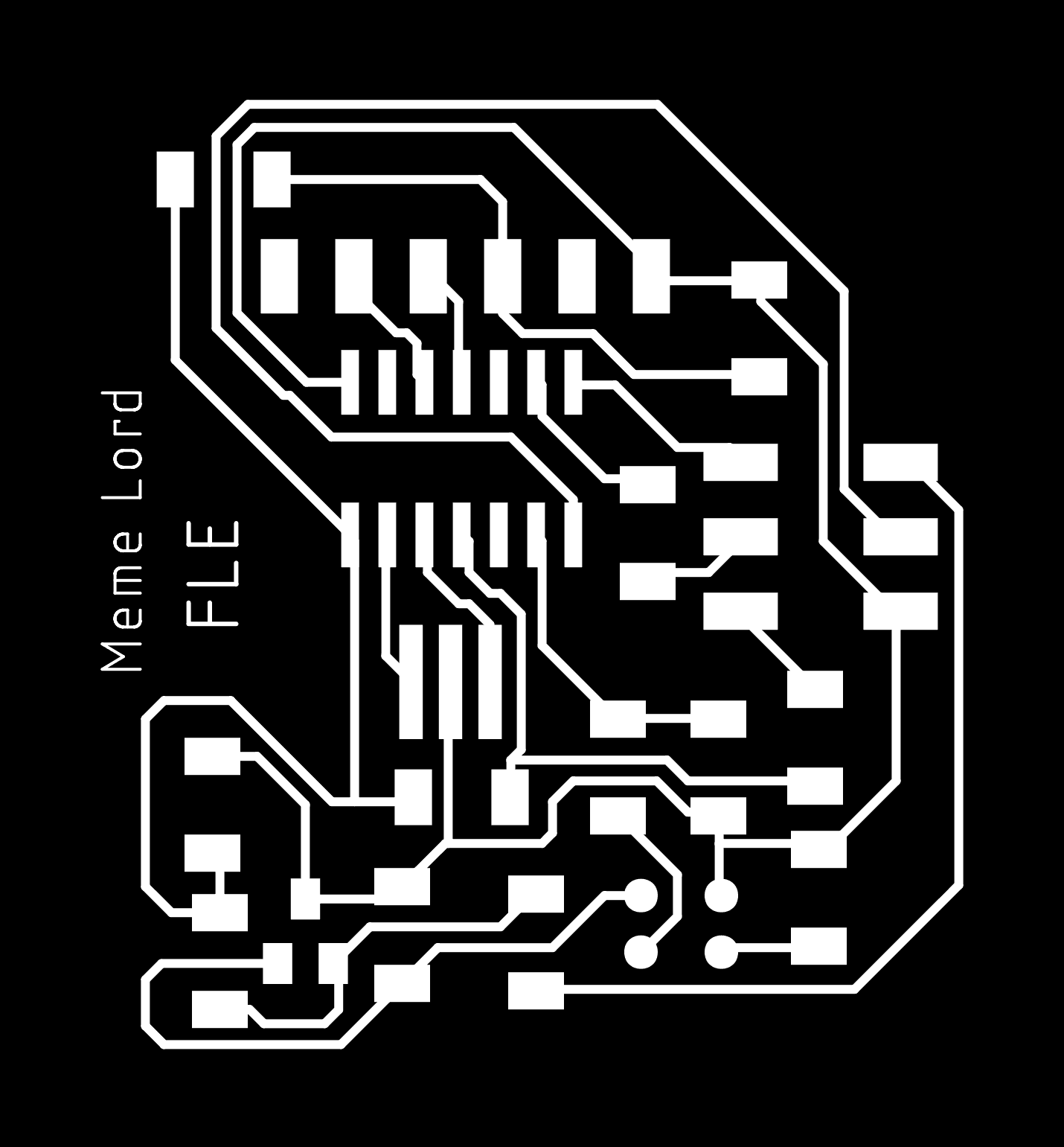
After finishing the PCB design, I exported two PNG images, one for top traces and the other one for the board outline cut.

PCB PNG Fabrication Files Download
PCB Fabrication
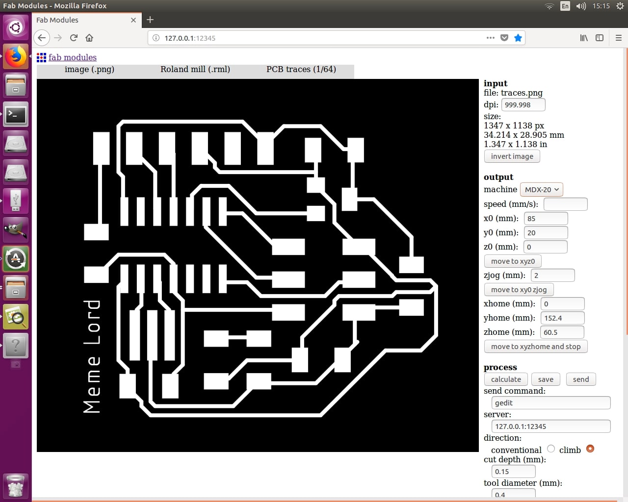
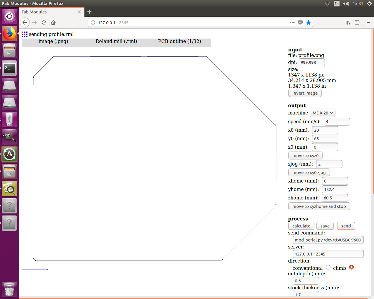
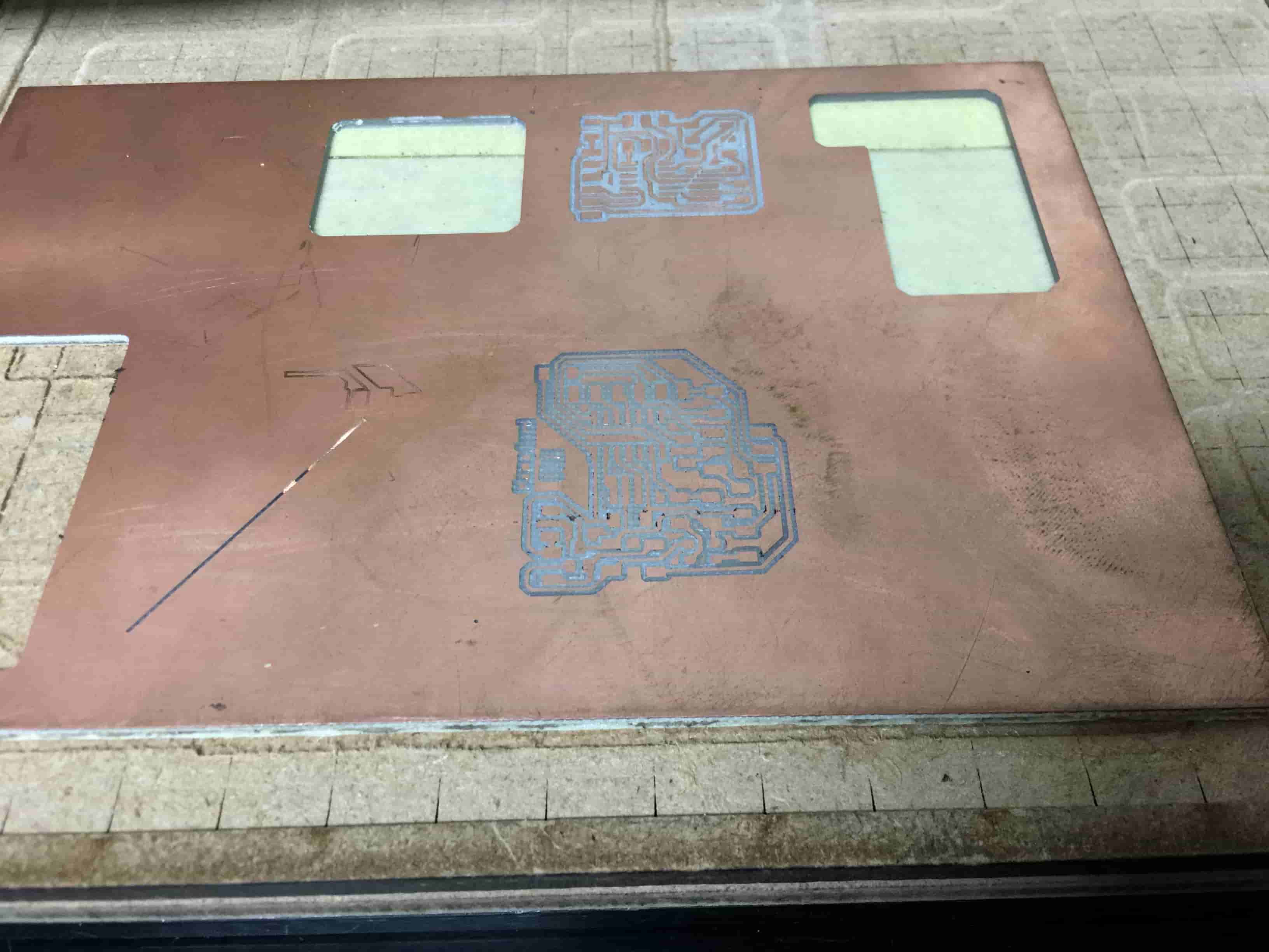
Now it’s time for fabricating the board, We at Fab Lab Egypt have a Roland MDX-20 CNC Milling machine, using the Fab Modules as a CAM software for translating the PCB PNG files to Gcode.
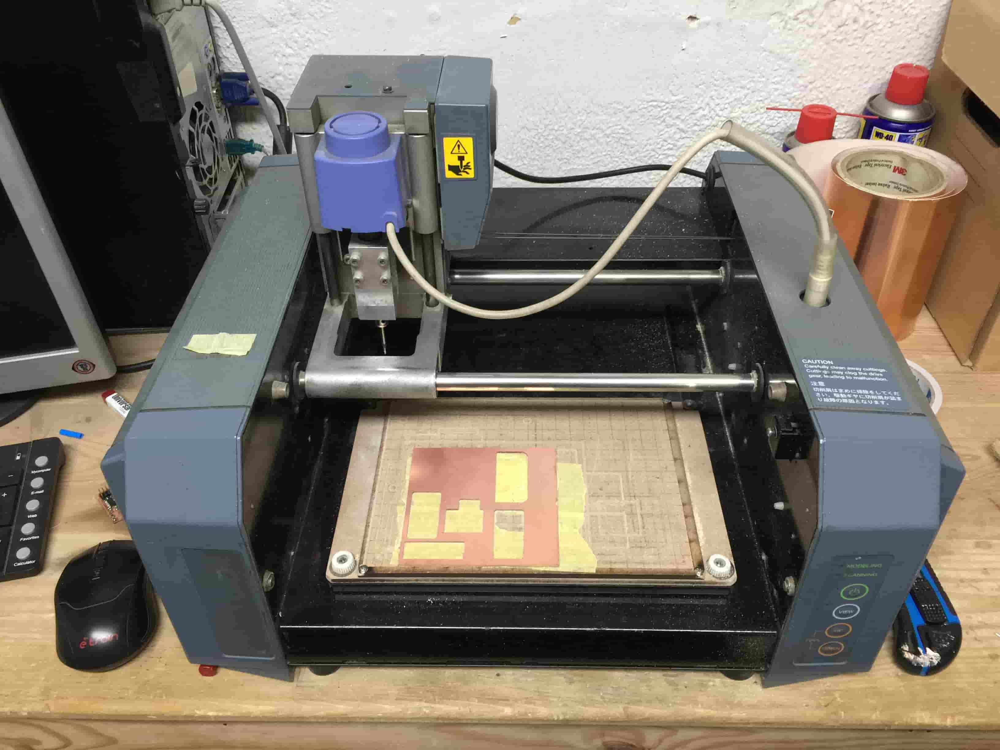
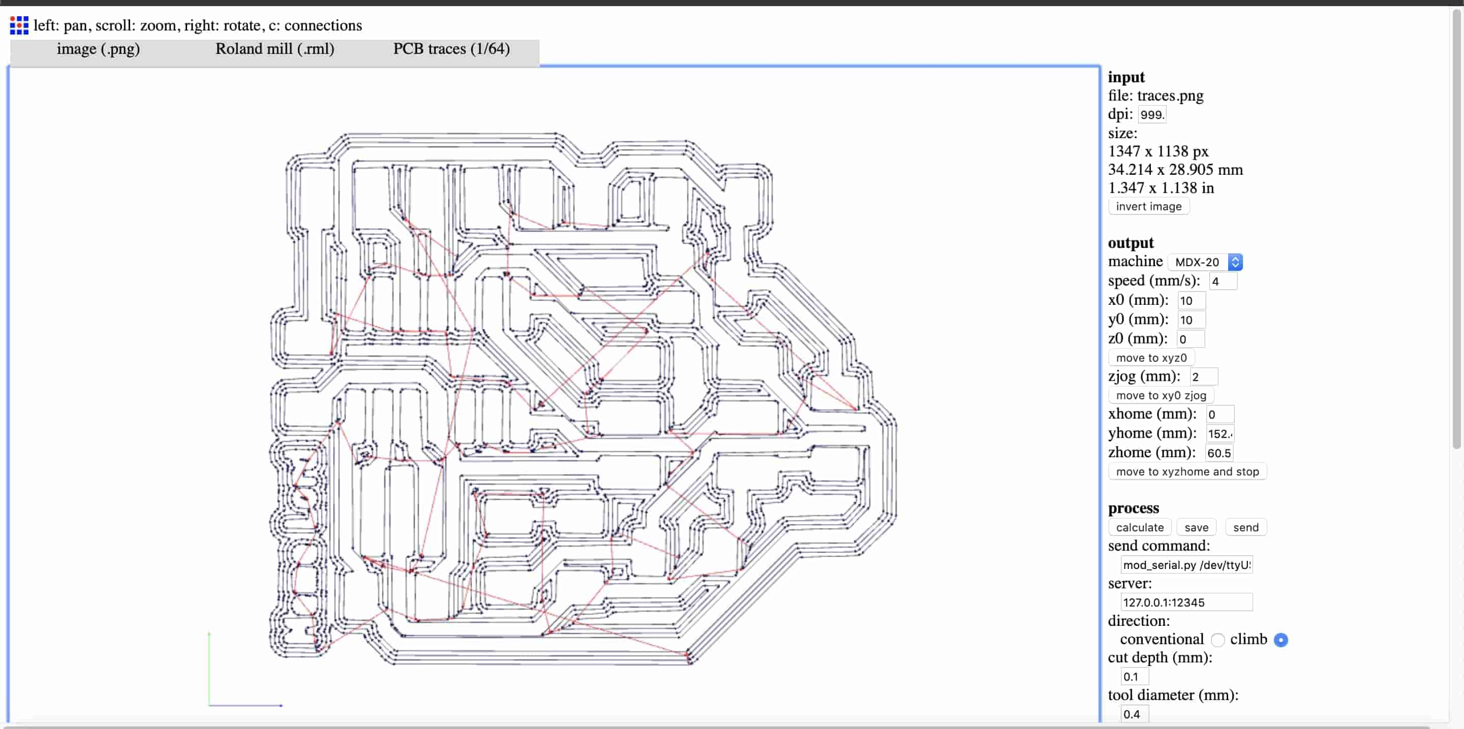
We gonna fabricate our board on two steps, the first step is to make the board traces, then to make the PCB outline cut. In the first step, we need to import the board traces PNG image to fab modules to generate the toolpath.
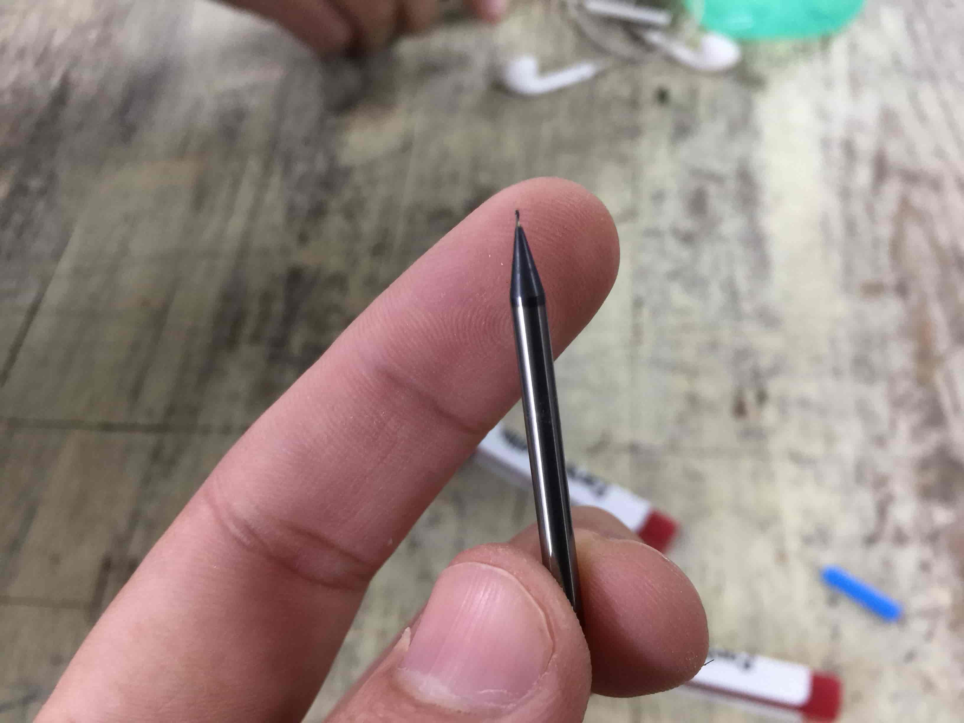
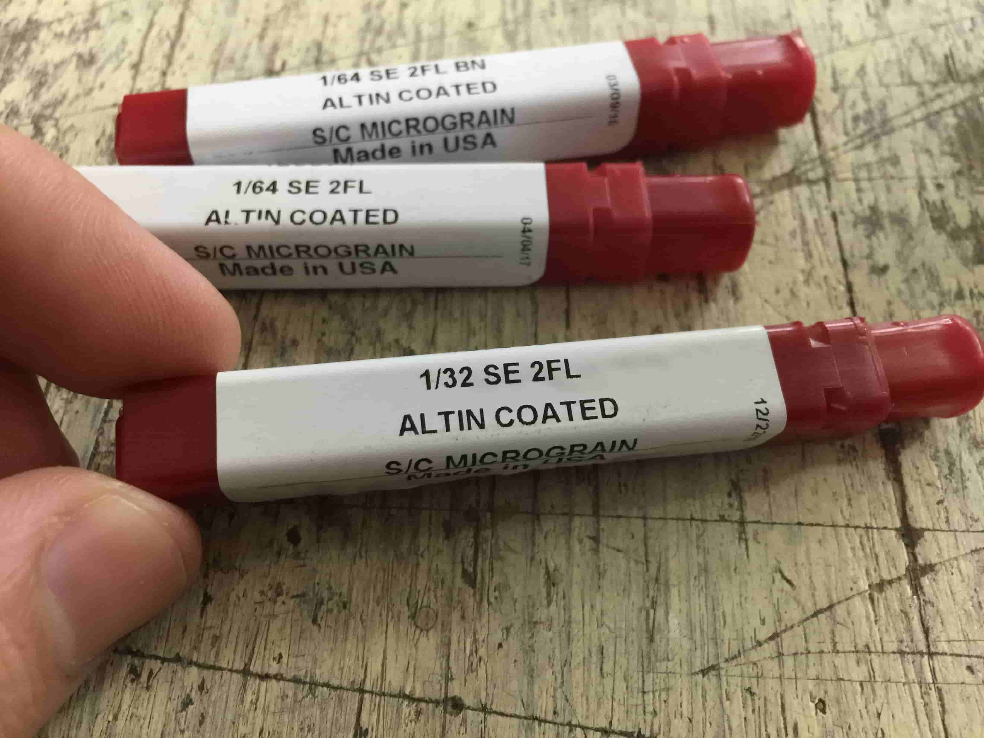
Now we need to install the 1/64inch end mill on the machine collet. In the traces making step we use the 1/64inch endmill, and the 1/32inch endmill to cut the PCB outline.
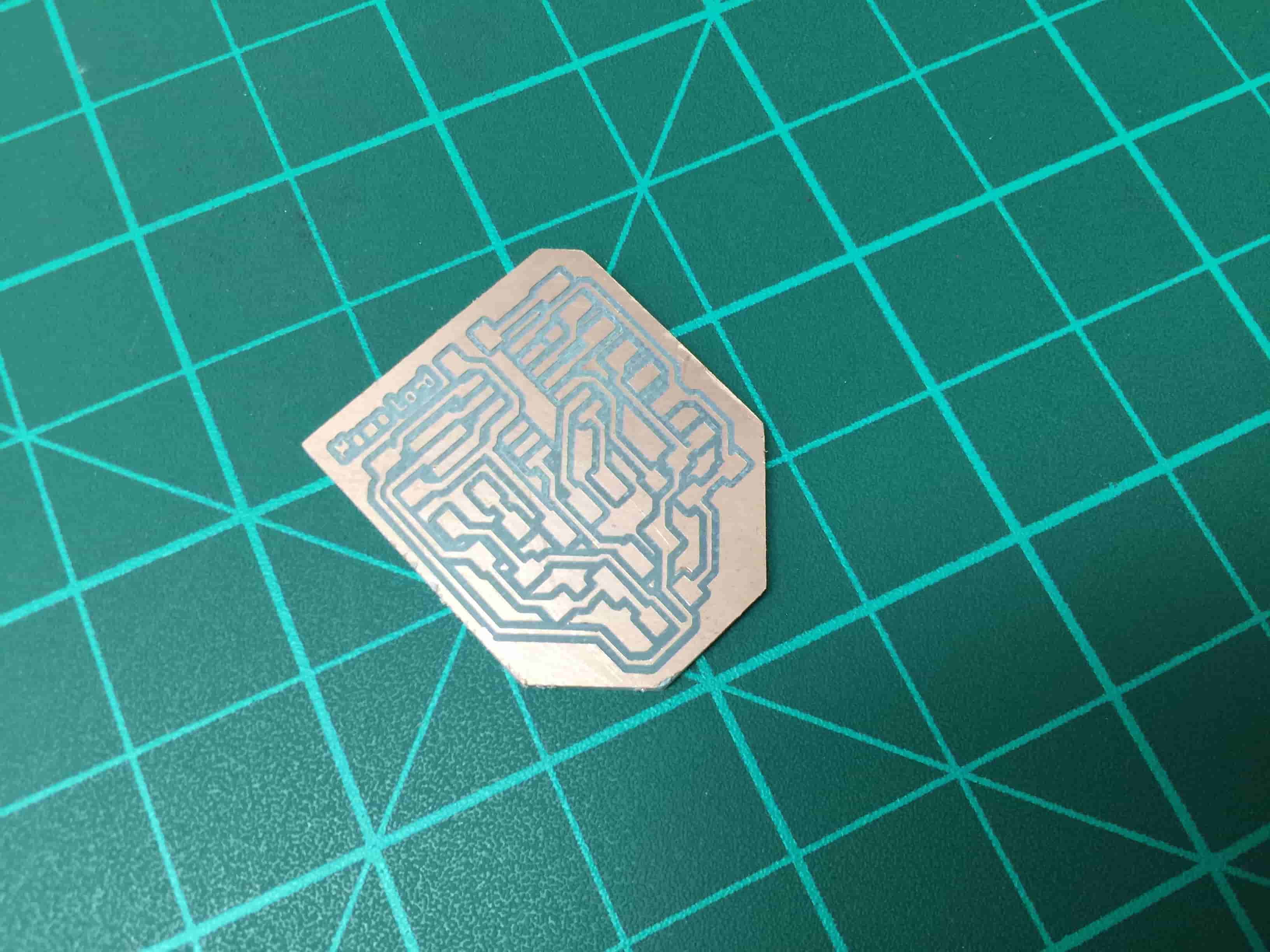
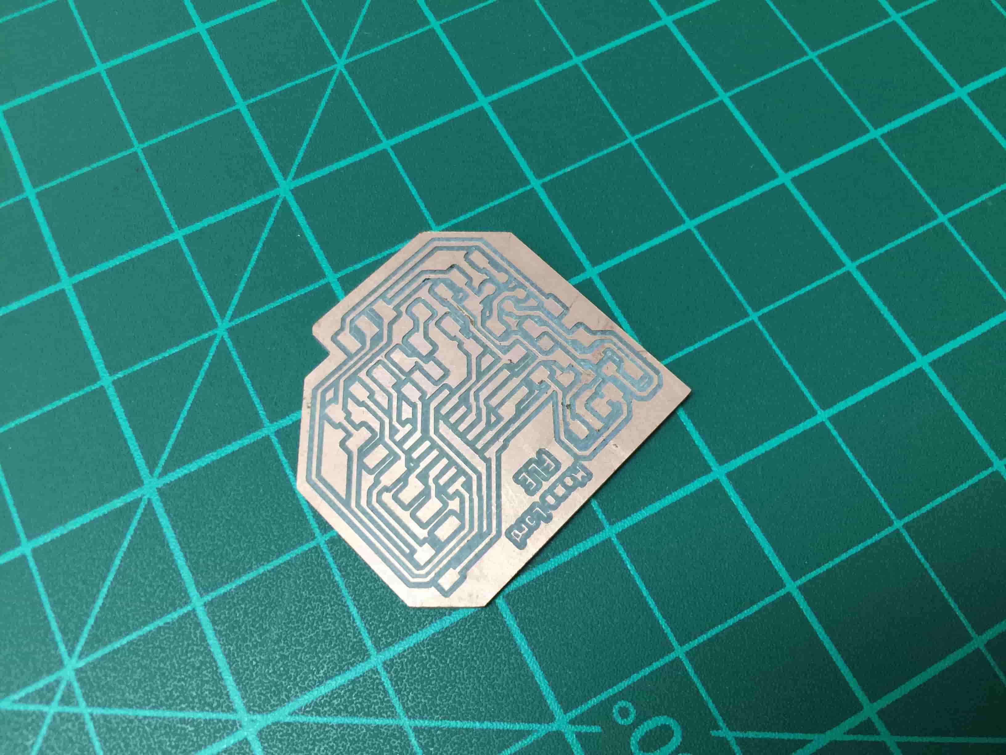
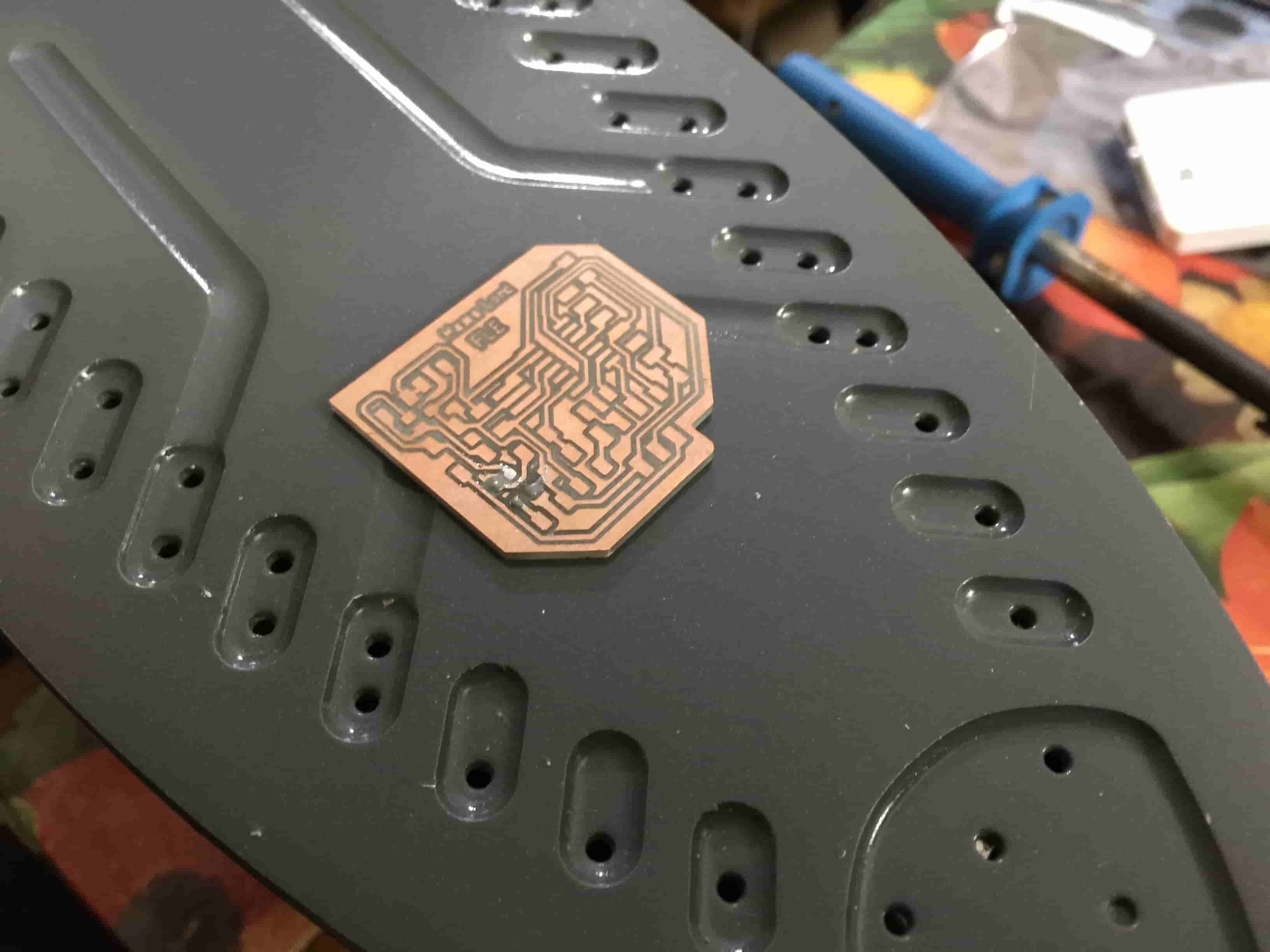
After setting the machine origin and setting the endmill Z-axis position. It’s the time to send the Gcode to the machine to start working. After finishing the PCB traces, here are the results. Pretty cool ha :D
since we need to cut the PCB outline, first, we have to change the endmill to the 1/32inch one. Then, import the PCB outline PNG image to Fab Modules, calculate the toolpath, then send the job to the machine.
Soldering the PCB
Now, we need to get all the components that we need to use from the Fab Lab Inventory, here is a list contains all the used hardware.
| Part Number | Description | Quantity |
|---|---|---|
| ATTINY44A-SSU-ND | IC AVR MCU 4K 10MHZ 8SOIC- | 1 |
| XC1109CT-ND | CER RESONATOR 20.00MHZ SMD | 1 |
| S1143E-36-ND | SMT RT Angle Male Header 0.1" (36pos) | 1 |
| 609-5161-1-ND | 6 Positions Header Connector 0.100" SMD | 1 |
| 445-1423-1-ND | CAP CER 1UF 50V X7R 10% 1206- | 1 |
| 399-4674-1-ND | CAP CERAMIC .1UF 250V X7R 1206- | 1 |
| 311-10.0KFRCT-ND | RES 10.0K OHM 1-4W 1% 1206 SMD | 1 |
| 311-499FRCT-ND | RES 499 OHM 1-4W 1% 1206 SMD | 1 |
| 311-0.0ERCT-ND | RES 0 OHM 1-4W 1% 1206 SMD | 1 |
| 160-1169-1-ND | LED Green CLEAR 1206 SMD- | 1 |
| 620-1402-1-ND | SENSOR LINEAR ANALOG SOT23W | 1 |
Getting all the components infront of you and make sure that there’s noting is missing. Everything is fine? Ok, Happy Soldering :D
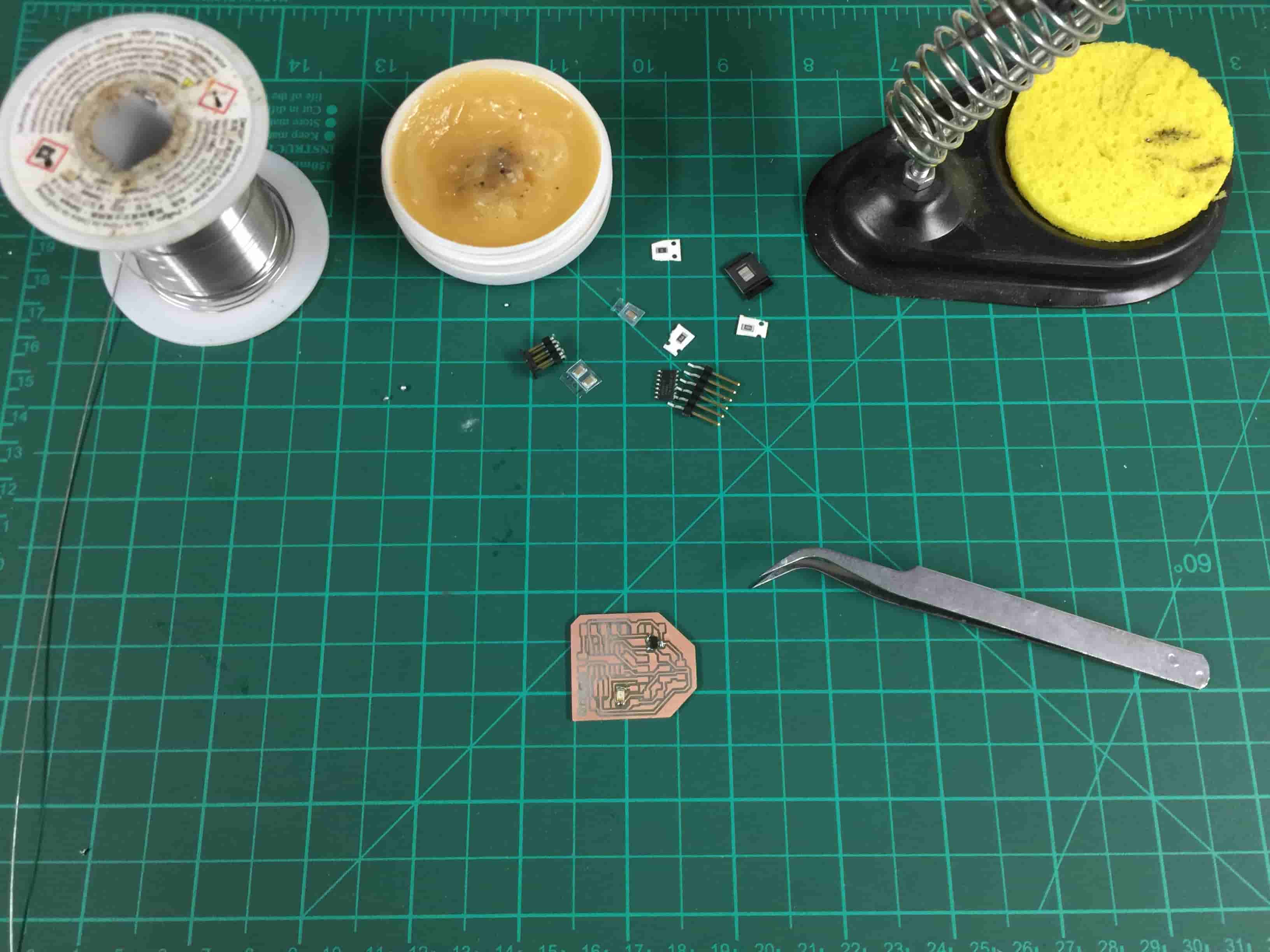
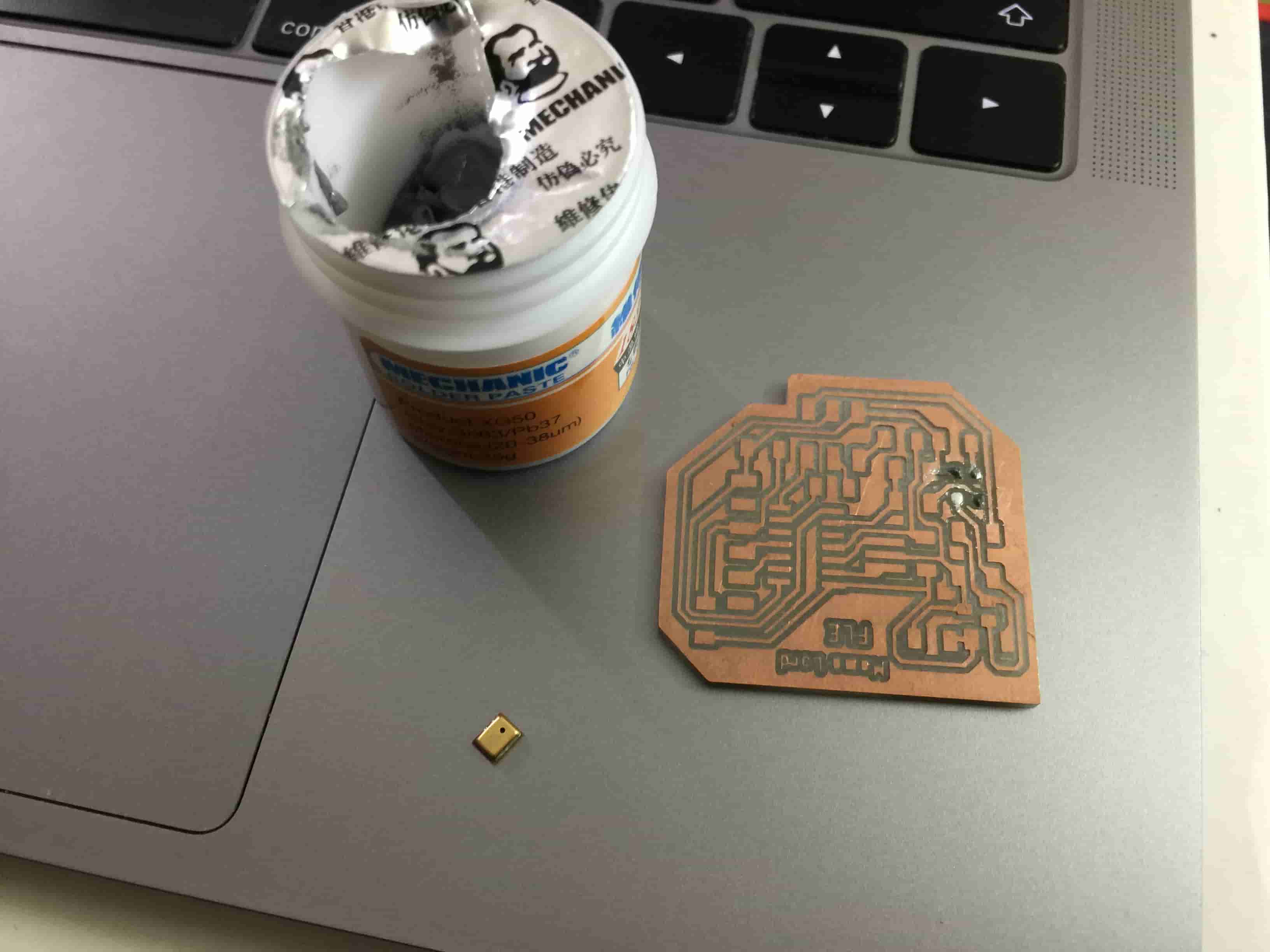
I like soldering the small(lower) components first then start soldering the bigger(higher) ones, it make the soldering process easier. I used the solder paste and hot air gun to solder the ATtinny44 on the board and it went great.
Programming the board
After Soldering the board, it’s time to test if your board is working or not! I wrote a small program on Arduino IDE to test the board.
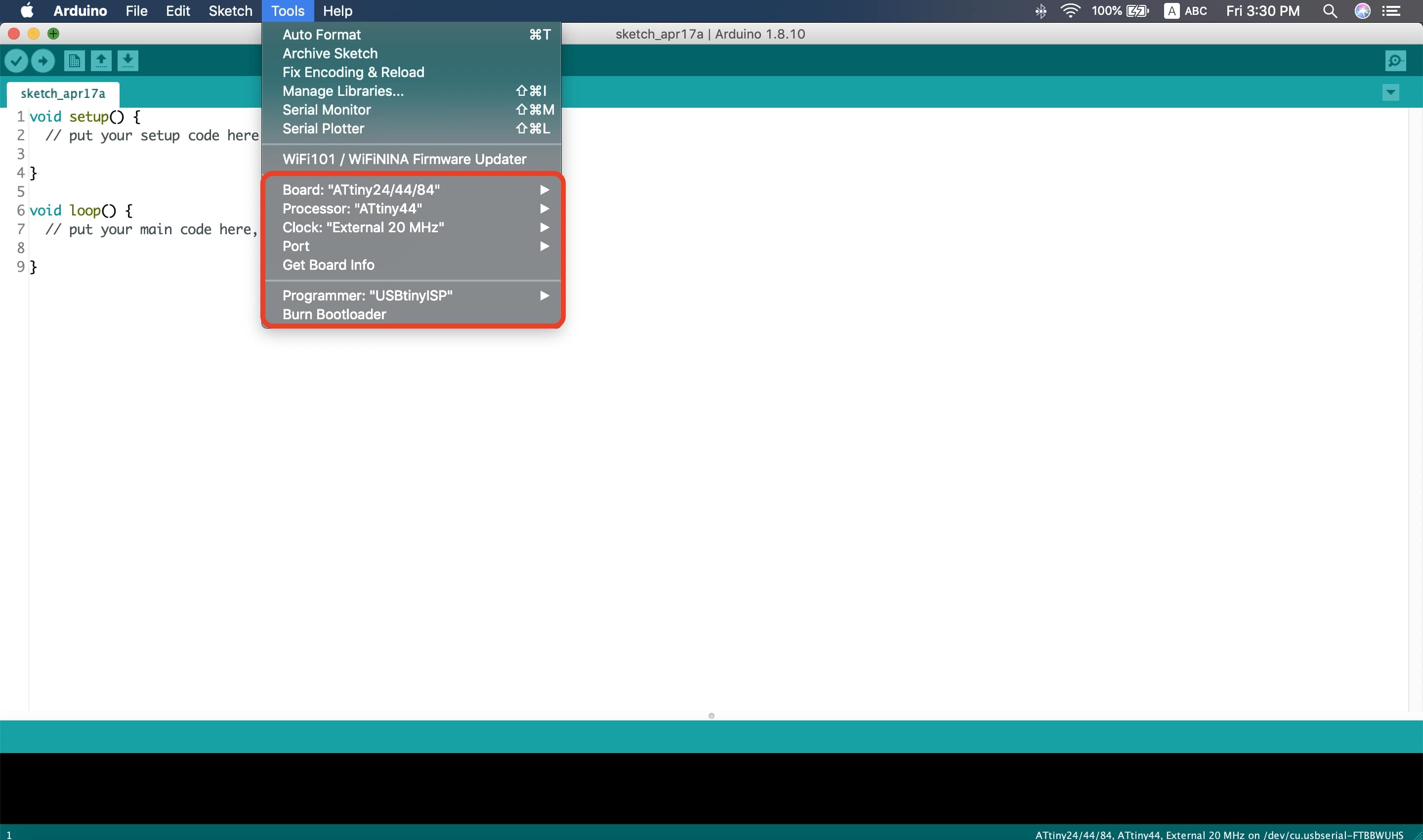
First, I burned the bootloader to the board to set the clock speed. Then selected “USBTinyISP” as my programmer. For more details about this part please check out the Embedded Programming week’s assignment.
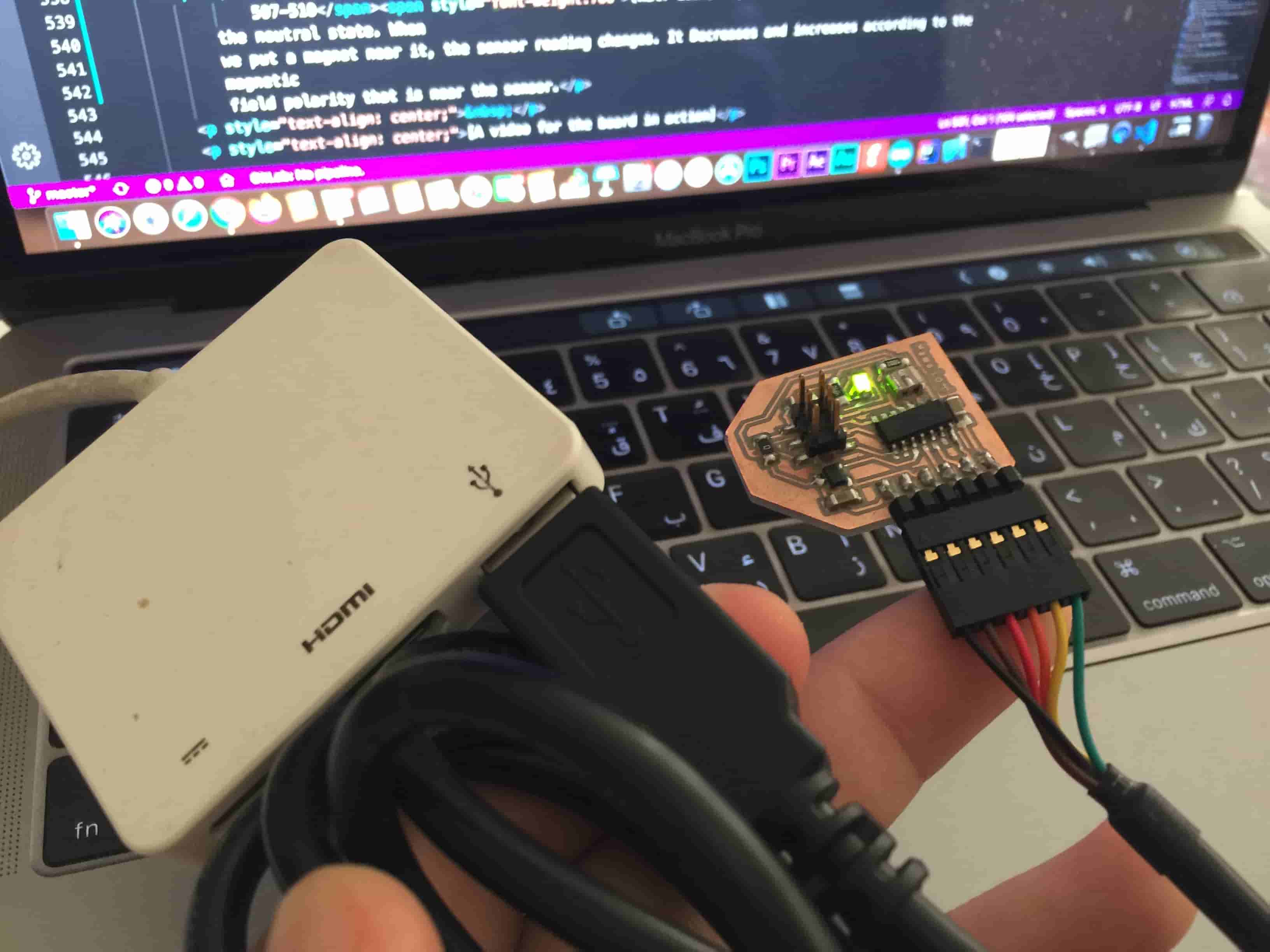
The program is very simple, I just read the sensor data and print it on the serial monitor. I’m using the USB to TTL Serial Cable to make a serial communication between my board and my computer.
                #include <SoftwareSerial.h>
                    #define hallEffectSensor A3
                    SoftwareSerial mySerial(2, 1); // RX, TX
                    void setup() {
                      mySerial.begin(9600);
                      pinMode(hallEffectSensor, INPUT);
                    }


                    void loop() {
                      int sensorReading = analogRead(hallEffectSensor);
                      mySerial.println(sensorReading);
                      delay(10);
                    }
Source Code Files Download
I didn’t face any problems in the drivers installation part, If you faced any of them, you can download the FTDI drivers from this link.
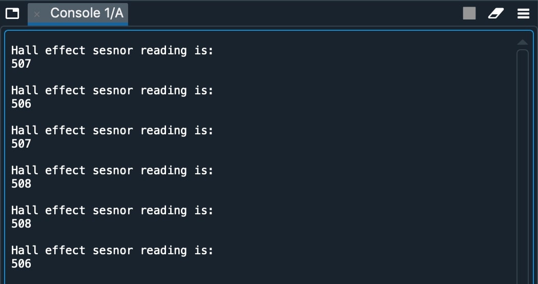
Now, we see that the sensor reading being printed on the Serial monitor is about 507-510(half 1024) which is the sensor reading in the neutral state. When we put a magnet near it, the sensor reading changes. It Decreases and increases according to the magnetic field polarity that is near the sensor.
Making a GUI using Python and Tkinter
We will build a GUI control panel using Tkinter and PySerial to print the sensor readings on it instead of the Arduino IDE Serial Monitor. We don’t need to change the Arduino Code that we wrote before to test the sensor, since it sends sensor readings to the serial port which the Python code will be listening to. Luckily, Python has a good open source community and comes with a Serial library called PySerial designed for just these kinds of things!
to be able to use the Serial communication with Python you have to install the PySerial library, it doesn’t come by default with Python. Here’s a link showing how to install PySerial. And here’s a link too showing how to install Tkinter in case you don’t have it on your machine.
Now I wanna display the sensor data on the Python terminal to make sure that my PySerial is listening correctly to my port. Here’s the same previous C Code. upload this code to your board using your programmer, then disconnect your programmer and connect your board with your laptop using the FTDI Cable.
                #include <SoftwareSerial.h>
                    #define hallEffectSensor A3
                    SoftwareSerial mySerial(2, 1); // RX, TX
                    void setup() {
                      mySerial.begin(9600);
                      pinMode(hallEffectSensor, INPUT);
                    }


                    void loop() {
                      int sensorReading = analogRead(hallEffectSensor);
                      mySerial.println(sensorReading);
                      delay(10);
                    }
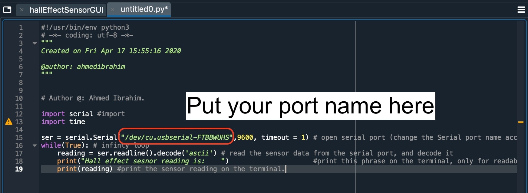
After uploading the C code, we need to run our Python code that listens to the Serial port. Don’t forget to change the port name to your board port name.
                # Author @: Ahmed Ibrahim.

                import serial #import
                import time

                ser = serial.Serial("/dev/cu.usbserial-FTBBWUHS",9600, timeout = 1) # open serial port (change the Serial port name according to yours.)
                while(True): # infinty loop
                    reading = ser.readline().decode('ascii') # read the sensor data from the serial port, and decode it
                    print("Hall effect sesnor reading is:    ")                     #print this phrase on the terminal, only for readability
                    print(reading) #print the sensor reading on the terminal.
Everything works fine?! Now, we need to build the app GUI to make it look nicer. Using the Tkinter library that we mentioned before, we built a simple GUI that consists of some labels and frames. The frame width is decreasing and increasing according to the sensor data.
The PySerial library is responsible for retrieving the data from the serial port. The code is pretty simple please consider reading the code comments if you wanna know more details about it.
Also, here is a great blog talking about Tkinter and how to use it will help you a lot to understand the basics of tkinter library.
        # Author @: Ahmed Ibrahim.

        import tkinter as tk    #import Tkinter GUI Library
        import tkinter.font as tkFont    #import the Tkinter font library, to be able to change the font style and font size.
        import serial           #import PySerial Library to communicte with the your bpard over serial communication(Tx, Rx)

        ser = serial.Serial("/dev/cu.usbserial-FTBBWUHS",9600, timeout = 1)  # listen to the serial port at speed 9600.


        root = tk.Tk()      #initialize a new window
        root.geometry("1100x400") #setting the width and the height of the window (Width x Height).
        fontStyle = tkFont.Font(family="Lucida Grande", size=30)    #setting the font style and the font size.


        label = tk.Label(root, font=fontStyle)      #initialize a new label with the font style we initialezed before.
        label.pack(side=tk.TOP, fill = tk.X)        #place it in the top side of the window. and make it fill the width of the window.

        sensorReading = tk.Label(root, font=fontStyle)   #initialize a new label with the font style we initialezed before.
        sensorReading.pack(side=tk.TOP, fill = tk.X)     #place it in the top side of the window. and make it fill the width of the window.

        frame1 = tk.Frame(master=root, width = 500, height=200, bg="red")  #initialize a new frame with a red color.
        frame1.pack()


        while(True):                                                        # the main program (infinity loop blocks anything come after it)

            reading = ser.readline().decode('ascii')                        # read the sensor data from the serial port, and decode it then store it inside the "reading" variable.

            sensorReading.config(text = reading, foreground="white", background="black")    #update the "sensorReading label" with the data stored inside the "reading" variable, set the background color of the label to black, and the text color to white.
            label.config(text = "Sensor Reading value is:    ", foreground="white", background="black")      #set the "sensorReading label" to "Sensor Reading value is:    ", set the background color of the label to black, and the text color to white.
            frame1.config(width = reading)    # update the red frame width according the data stored inside the "reading" variable.

            root.update_idletasks()
            root.update()
Source Code Files Download
Making a MIC- based Board
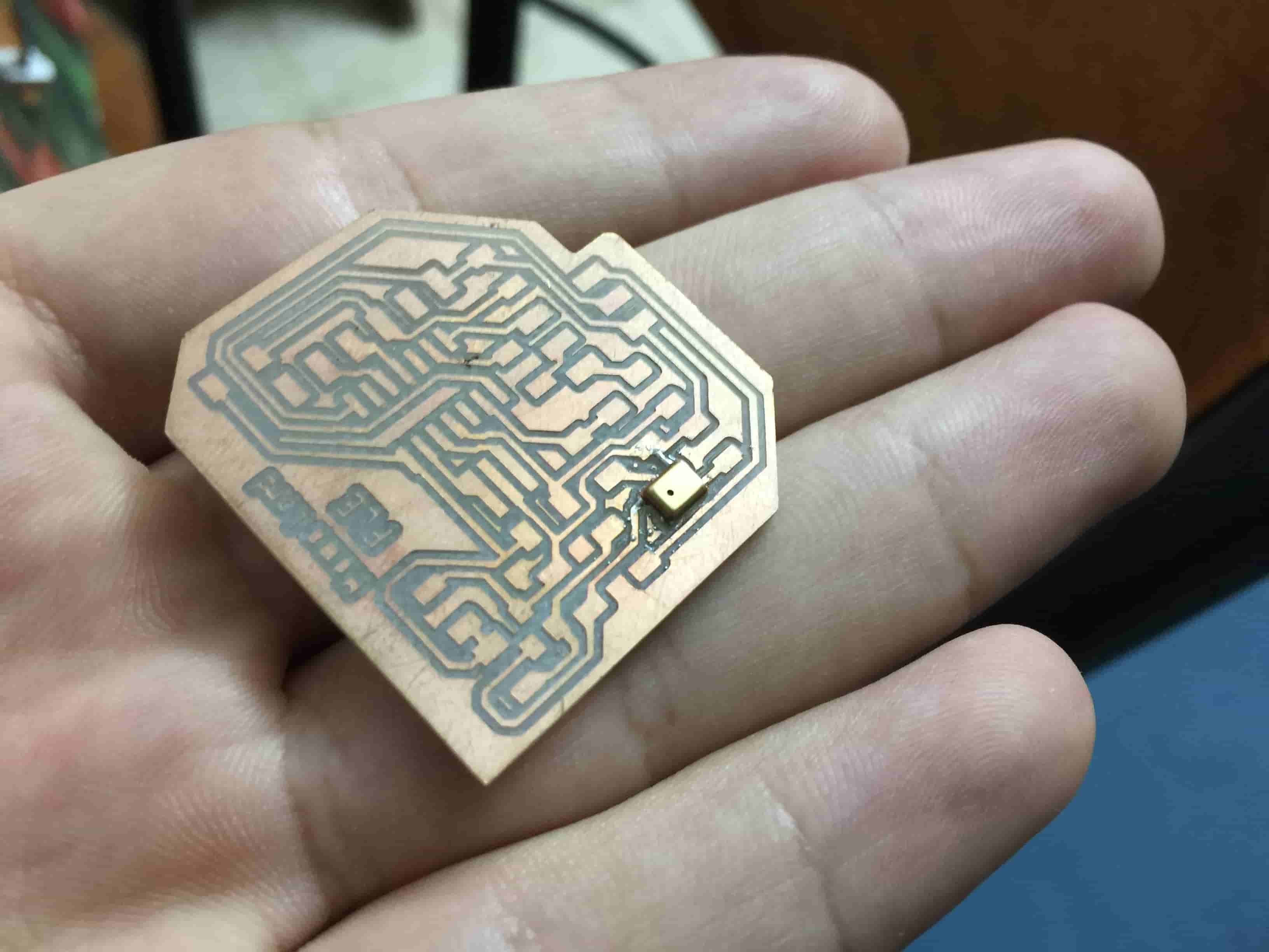
I was very curious about using the MEMS MIC specially that I didn't solder this type of components before. The MIC pads is hidden under it :D So I decided to give a try.
As we know before any designing process we need to know some information about that component, we need to know what's the recommended supply voltage for this component, its pinout, and how to connect it in the circuit.
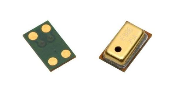
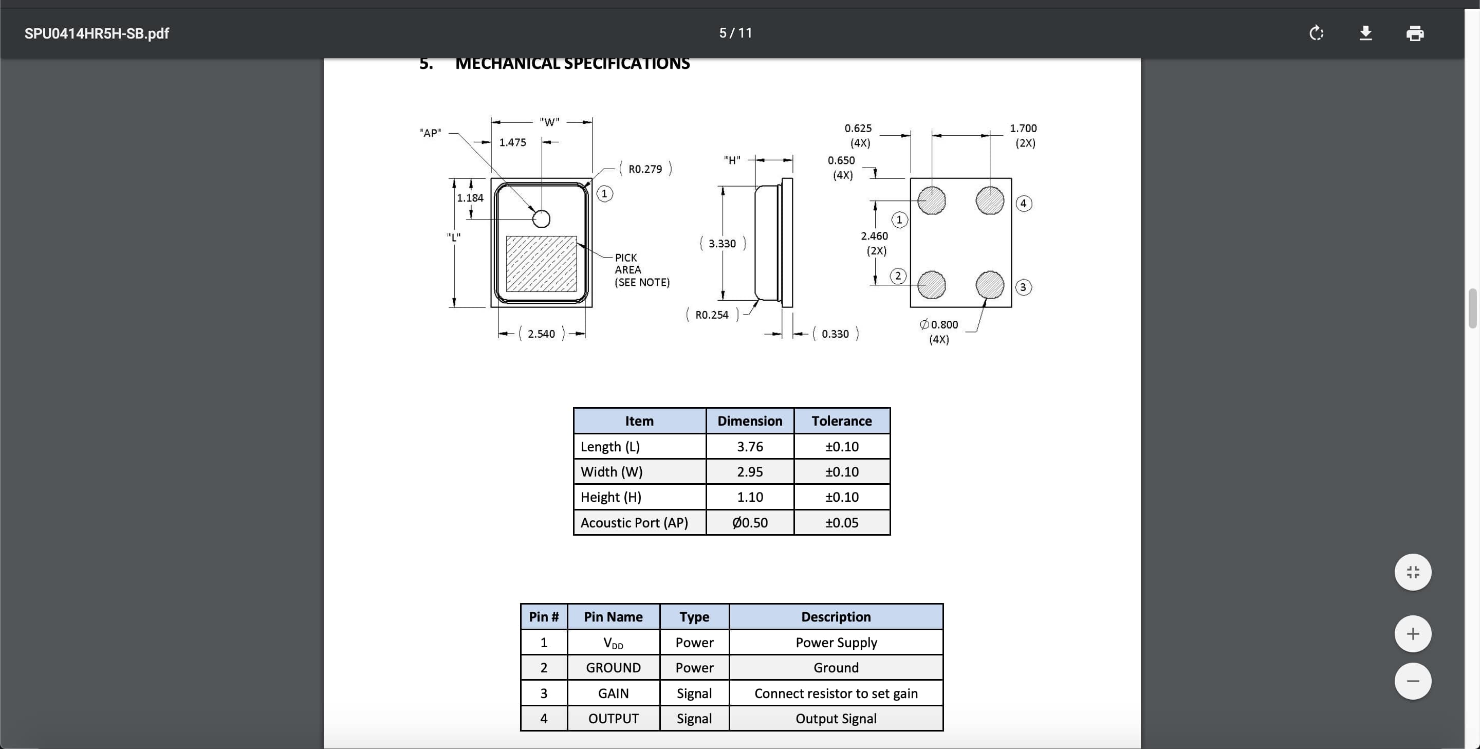
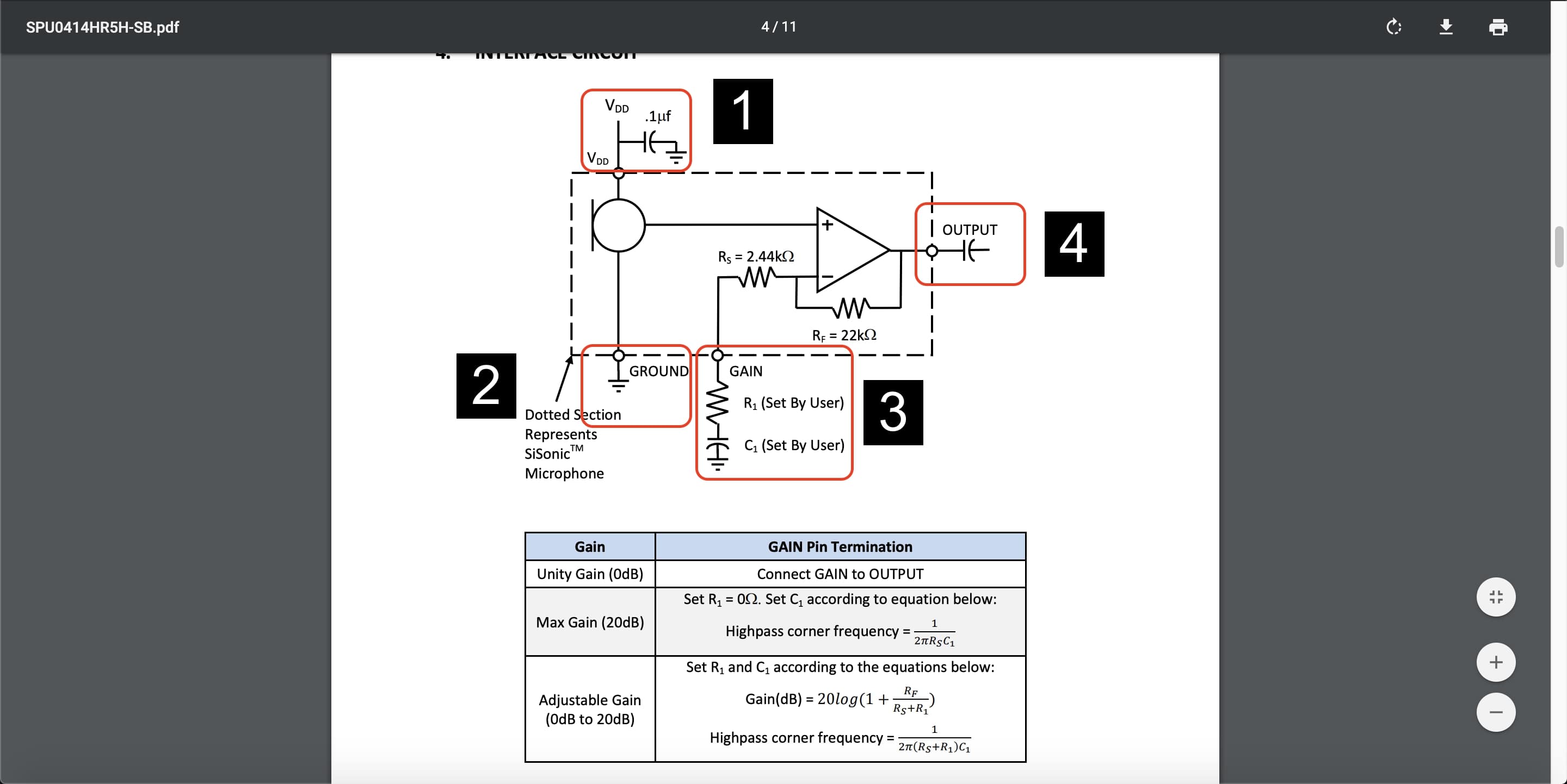
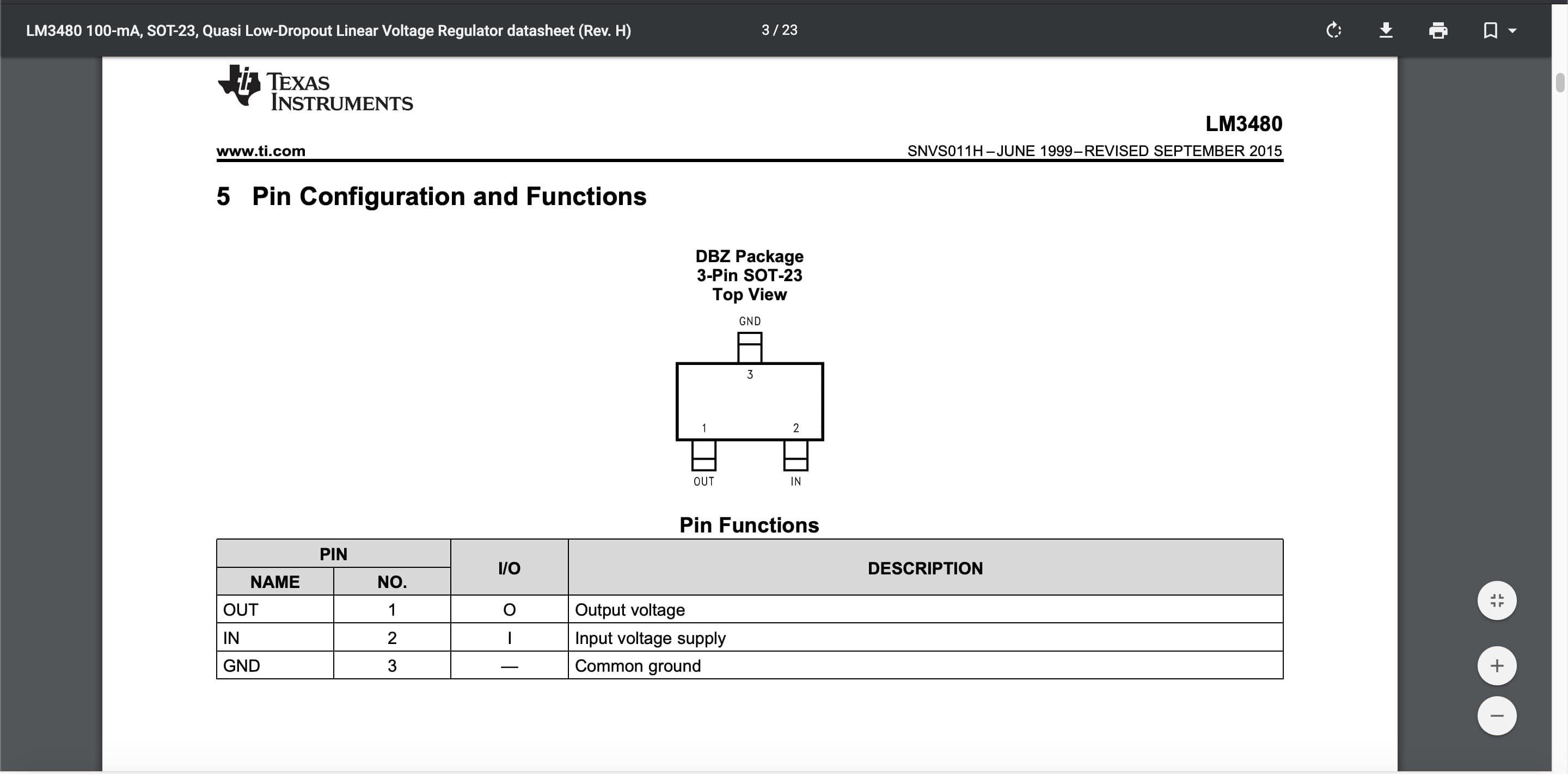
As we can see, the MIC has four terminals(VDD, GND, Gain, Output) and we can see in its datasheet the pin numbering and positions.
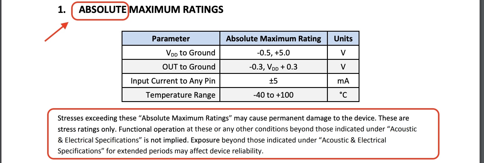
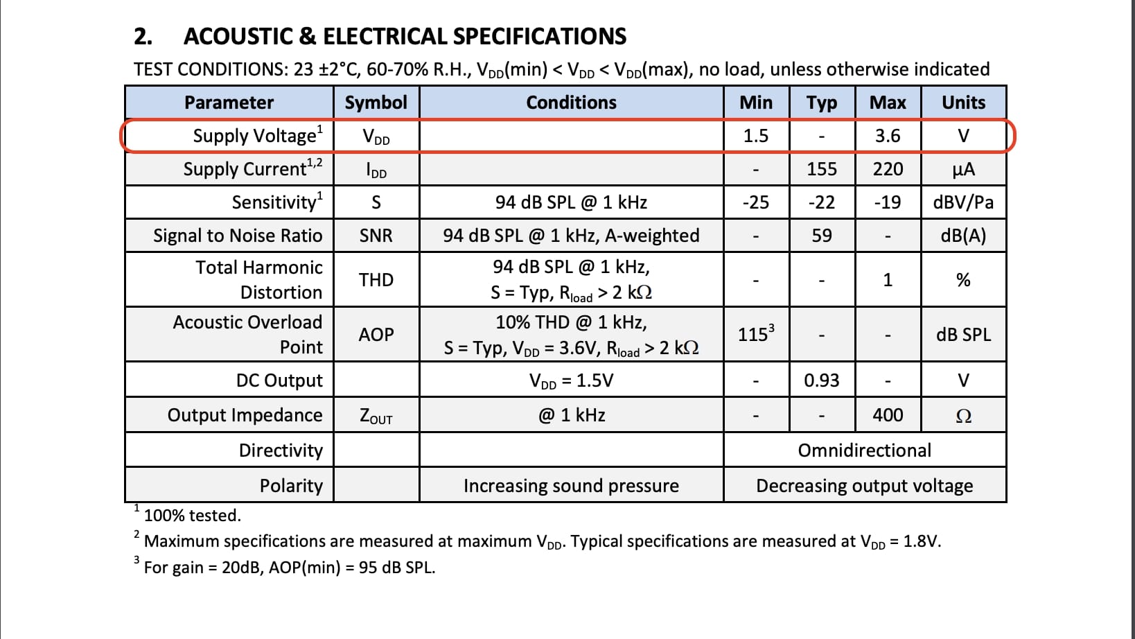
Now, we need to know how much voltage that MIC needs to work. Also we can find in the datasheet that the MIC can work on 5V but note that it’s the Absolute maximum rating and its not recommended to design your circuit upon these values. From the datasheet also we can find The recommended supply voltage which is 3.3 - 3.6V.
Also, in the datesheet we can find the typical application part that tells you how to connect this MIC.
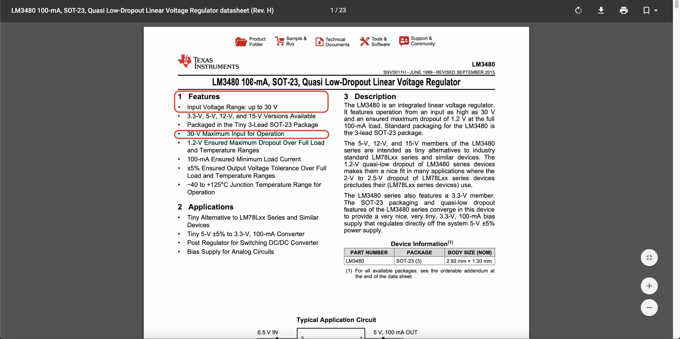
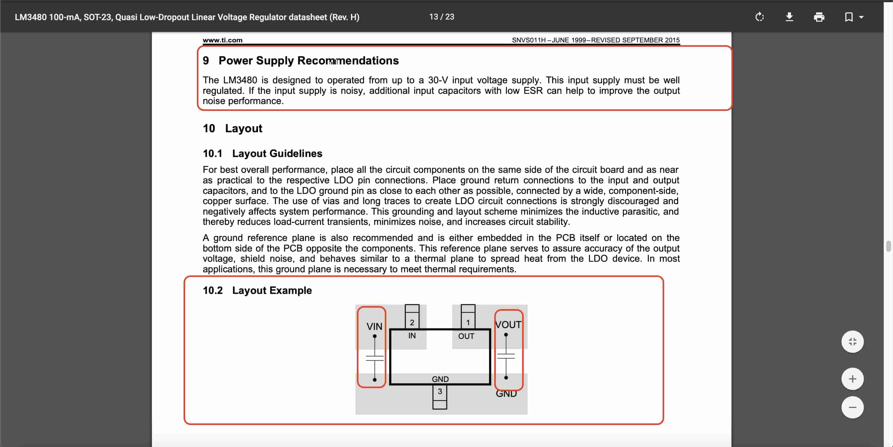
To supply the MIC with a 3.3V, we will use the LM3480IM-3.3 voltage regulator to convert the 5V that is coming from the PC/Laptop port to 3.3V. This voltage regulator can handle input voltage upto 30V.
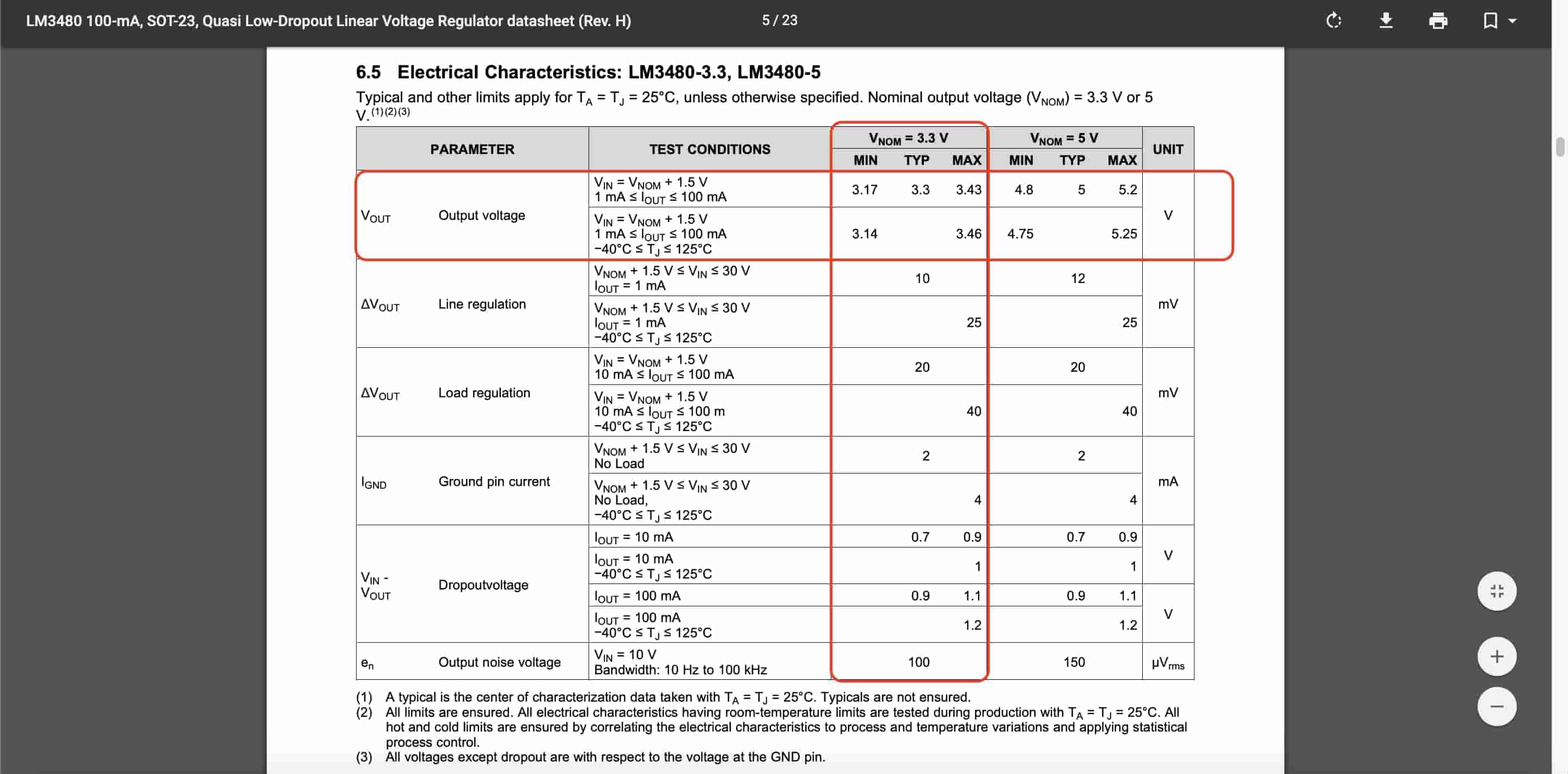
And here’s the pinout of the voltage regulator and how to connect it. It's recommended to connect two 0.1uf capacitors on the input and output pins. The voltage regulator Vout pin will go to the MIC to provide it with a 3.3V.

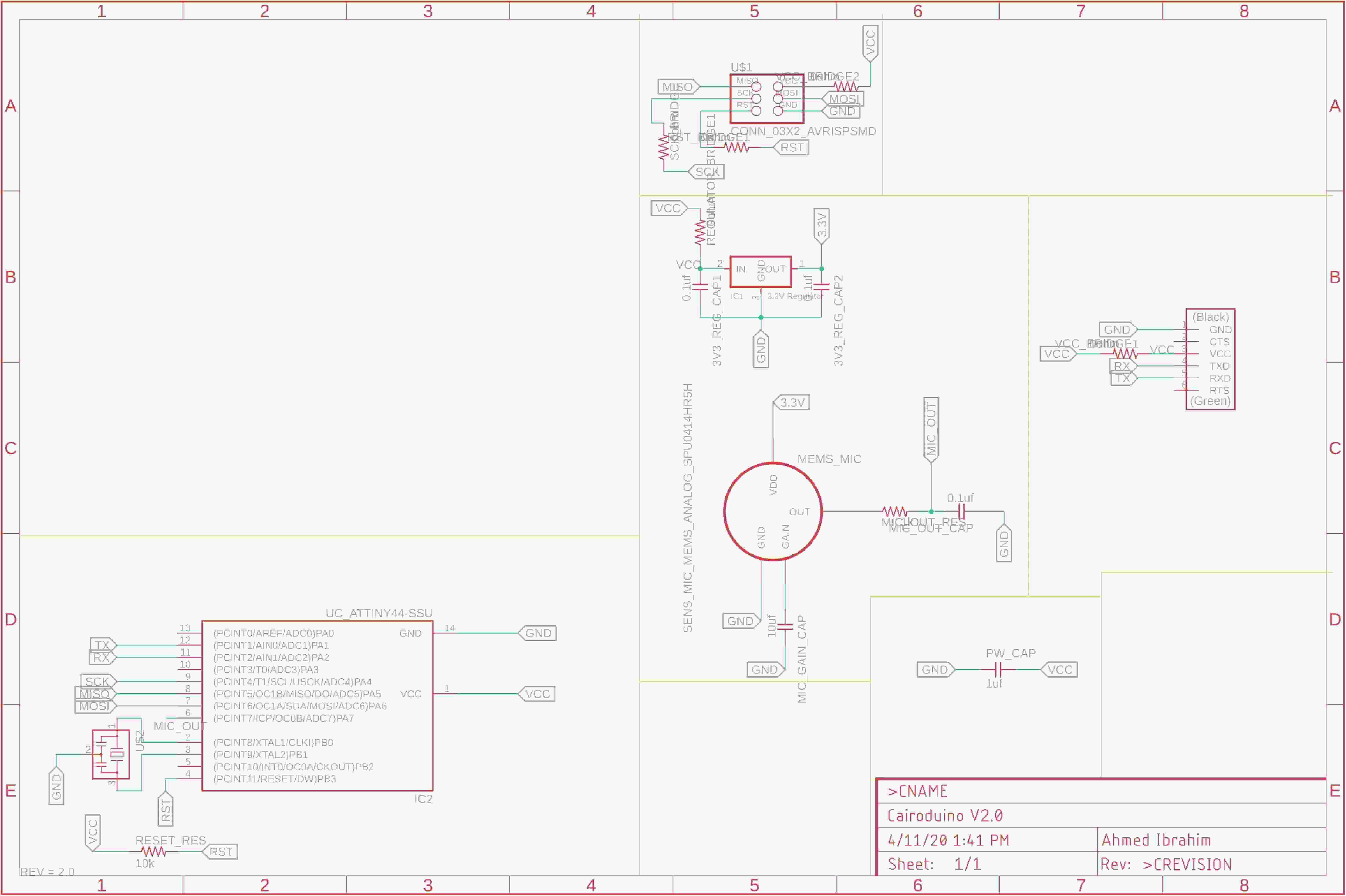
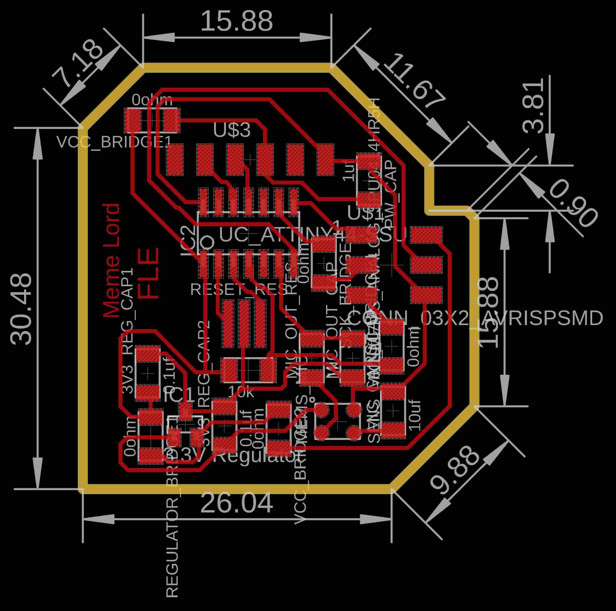
I designed the board using Eagle as usual. First we make the board schematic then we make the board layout.

PCB PNG Files Download
Fabricating and soldering the board
You already know fam, we are using the fab modules CAM software to generate the toolpath and the Gcode to send it to the awesome modela MDX-20 to mill and cut our board.
After finishing fabricating the board, it’s time to solder the components. Here are all the electronics components that we used in this board.
| Part Number | Description | Quantity |
|---|---|---|
| ATTINY44A-SSU-ND | IC AVR MCU 4K 10MHZ 8SOIC- | 1 |
| XC1109CT-ND | CER RESONATOR 20.00MHZ SMD | 1 |
| S1143E-36-ND | SMT RT Angle Male Header 0.1" (36pos) | 1 |
| 609-5161-1-ND | 6 Positions Header Connector 0.100" SMD | 1 |
| 587-1352-1-ND | CAP CER 10UF 35V Y5V 1206- | 1 |
| 445-1423-1-ND | CAP CER 1UF 50V X7R 10% 1206- | 1 |
| 399-4674-1-ND | CAP CERAMIC .1UF 250V X7R 1206- | 3 |
| 311-10.0KFRCT-ND | RES 10.0K OHM 1-4W 1% 1206 SMD | 1 |
| 311-1.00KFRCT-ND | RES 1.00K OHM 1-4W 1% 1206 SMD- | 1 |
| 311-0.0ERCT-ND | RES 0 OHM 1-4W 1% 1206 SMD | 5 |
| 423-1134-1-ND | MIC MEMS ANALOG OMNI -22DB | 1 |
| LM3480IM3-3.3/NOPBCT-ND | IC 3.3V100MA LDO VREG SOT23- | 1 |
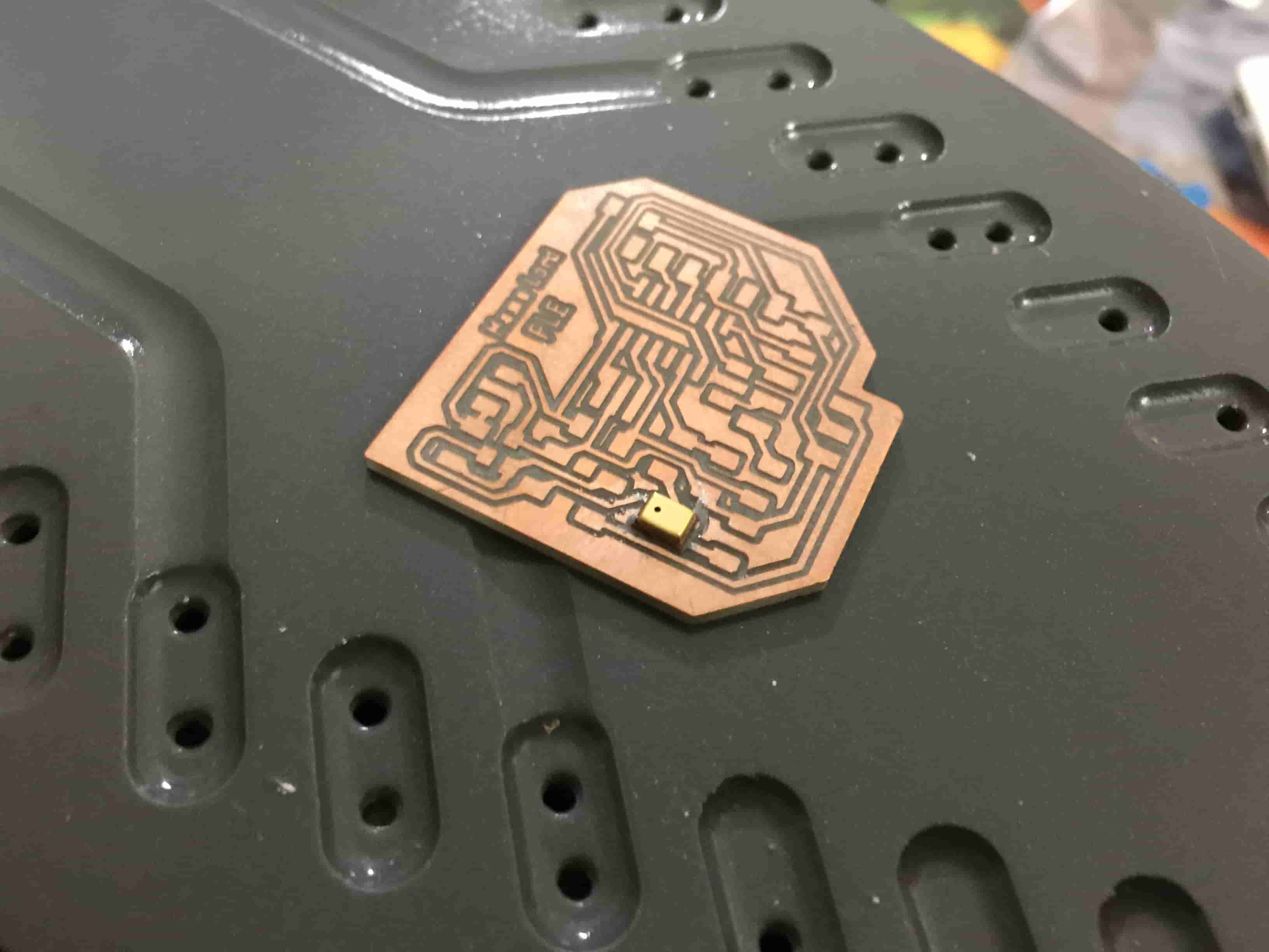
The most cool and hard part is to solder the MIC itself :D I watched a lot of techniques on how to solder that type of hidden pads components, the most amazing technique I saw is someone using a very normal clothes Iron to heat up the board after applying a solder paste on the pads. the board heats up, the solder paste melts, Voila your board is now soldered :D
Programming the board
To test the board I wrote a simple code that prints the MIC readings on the Arduino IDE Serial monitor. And it works :D
        # Author @: Ahmed Ibrahim.

        #include

            #define MIC A7
            int MICReading = 0;

            SoftwareSerial mySerial(2, 1); // RX, TX

            void setup() {
              pinMode(MIC, INPUT);
              mySerial.begin(9600);
            }

            void loop() {
              MICReading = analogRead(MIC);
              mySerial.println(MICReading);
              delay(10);
            }