This wasn't just about cutting wood and plugging in wires. I had to treat this as a full engineering integration challenge. Here is how I set up
the physical and digital systems, how I got them to talk to each other, and how I tested them to make sure nothing smoked.
My System Setup
I used a "hybrid" manufacturing approach. I didn't want to just glue things together; I wanted them to fit mechanically and be easy to maintain.
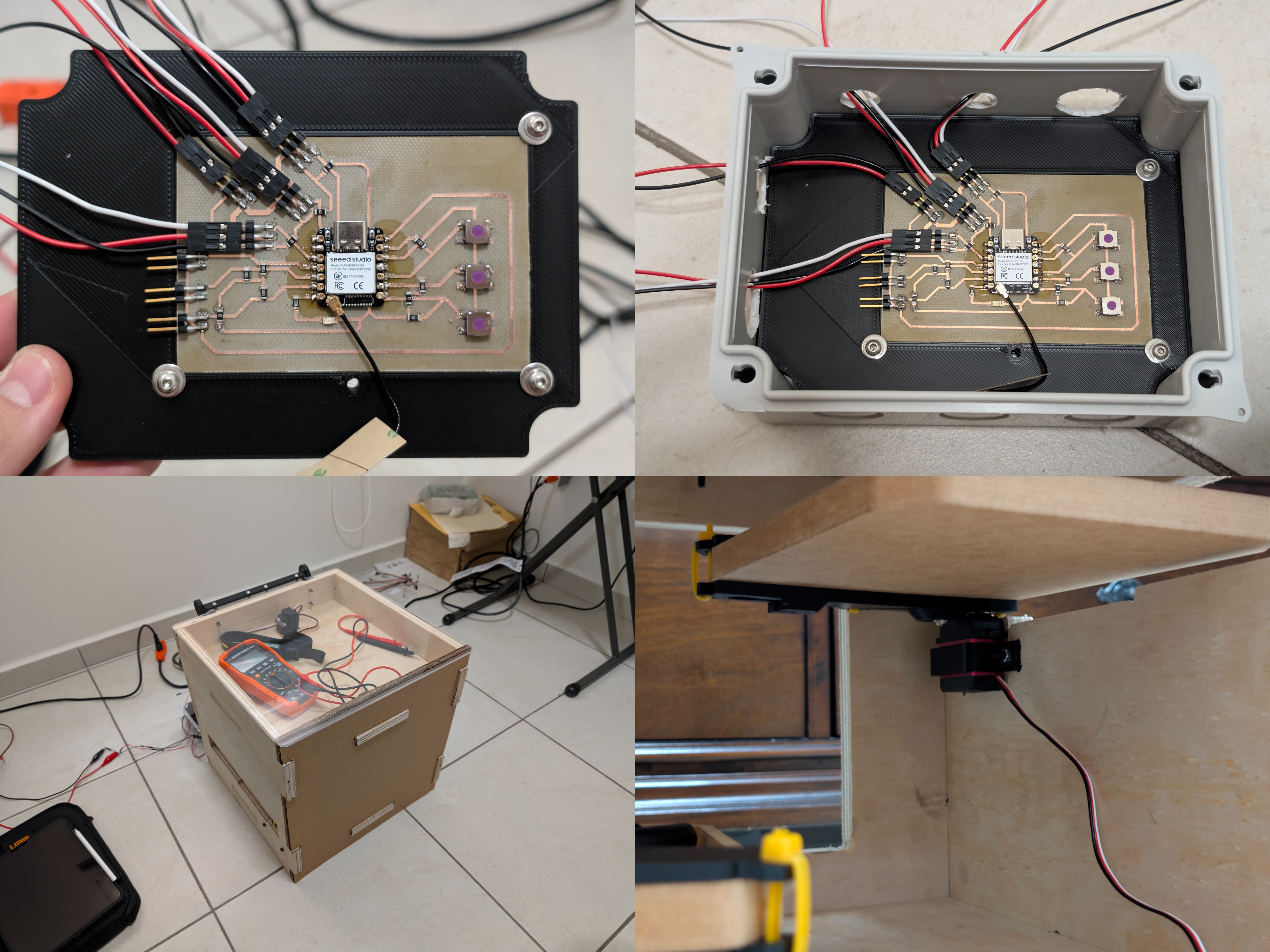
Mounting the Electronics: I didn't want my custom PCB floating around or shorting out on the table. I bought a standard electrical junction box and designed a custom 3D-printed backplate (the black piece inside the box). I bolted the PCB to that plate to act as a standoff, isolating the soldered bottom layer from the plastic case.
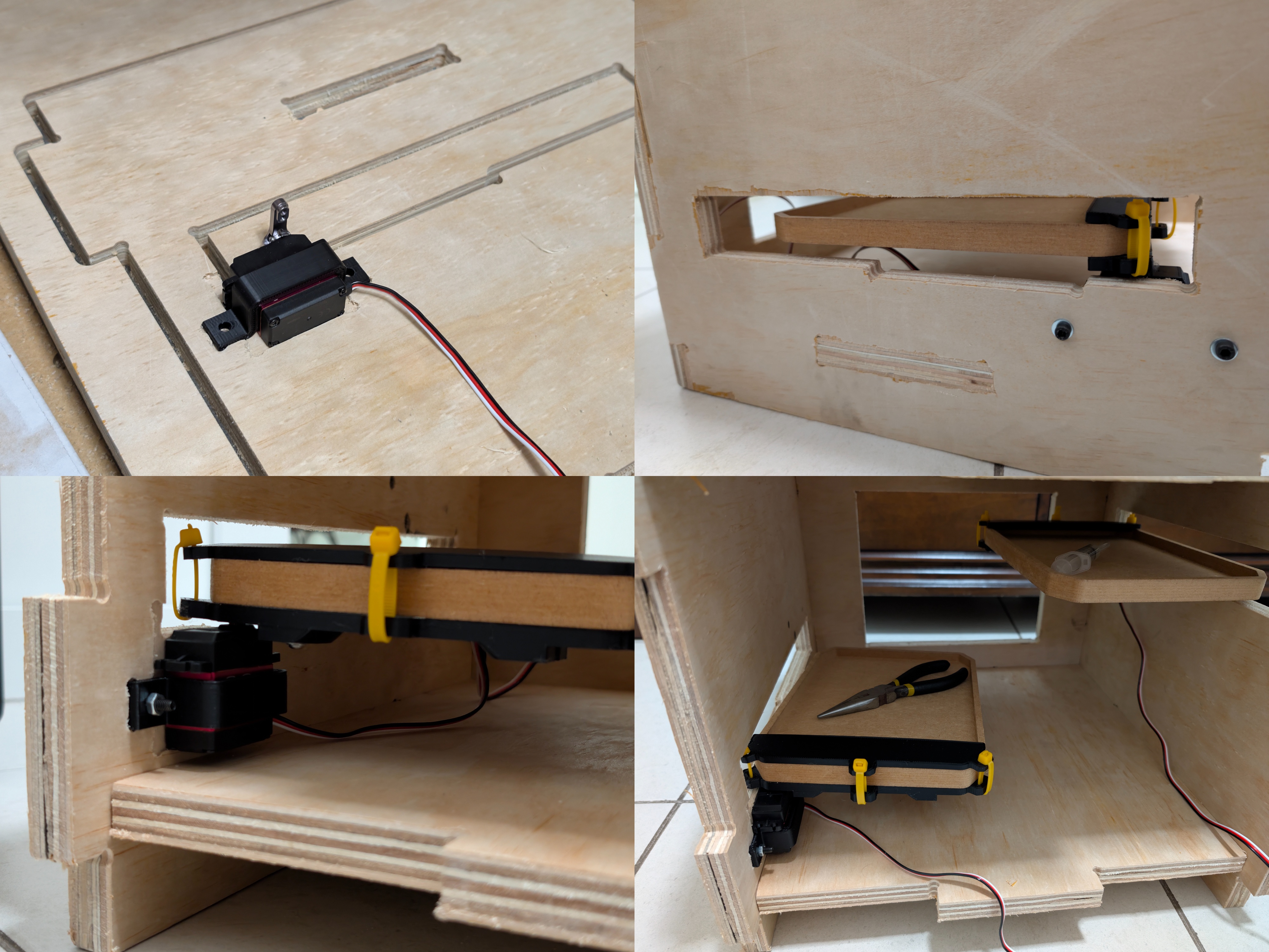
Installing the Servos: Putting screws directly into the side of plywood is a bad idea because the layers split. Instead, I CNC-milled specific "pockets" into the plywood walls. Then, I 3D printed custom PLA brackets that fit the MG90 servos perfectly and screwed those brackets into the wood. This kept the motors rigid and flush with the wall.
The Drawer Mechanism: Instead of a complex gear system, I went with a direct holding mechanism. The servos physically hold the drawers in place using 3D-printed mounts attached to the drawers. You’ll notice in the photos I used yellow industrial zip-ties to secure these mounts to the MDF drawers. This was a specific design choice: it allowed me to adjust the alignment instantly without damaging the wood.
How I Integrated the System
System integration is just a fancy way of saying "how I made the parts talk to each other." I focused on three main areas:
Standalone Network & Dual Control Strategy: I didn't want to rely on just one way to open the box.
The Wireless Way: I moved the logic onto the ESP32S3, setting it up as an Access Point (AP) to generate its own Wi-Fi network. This hosts the web interface directly on the chip.
The Physical Way: I realized I might not always have a phone or laptop in my hand when I'm working. So, I integrated 3 physical buttons directly onto the PCB. This creates a redundant control system—I can open the drawers via the web browser AP or just walk up and press the button if I'm not carrying a device.
Electromechanical Integration & Split Power: My PCB is the bridge between the code and the physical world. The ESP32 sends 5V logic signals to control the motors. To keep things stable, I split the power architecture: the PCB (brains) runs off an ANKER power bank via USB-C, while the servos (muscles) plug into a dedicated external power source. I designed the PCB headers to group the Signal, Power, and Ground pins together for each motor, which prevented me from crossing wires and blowing anything up.
Physical Routing: I ran the cabling along the internal corners of the chassis. I had to be careful here because the drawers slide back and forth; if a wire was loose, a drawer could catch it and rip the port off the PCB. I positioned the servos at the very back of the rails to get the best leverage to hold the drawers shut.
How I Tested It (Quality Assurance)
I didn't just turn it on and hope for the best. I followed a specific testing order:
Phase 1: The "Don't Blow It Up" Test: Before I even plugged the microcontroller in, I grabbed my Klein Tools multimeter. Since I milled the PCB myself, I had to be 100% sure I didn't leave a tiny sliver of copper connecting Ground to Power. I ran continuity checks on all the tracks. You can actually see my multimeter sitting on top of the box in the photos during this phase—that was my most used tool.
Phase 2: The Servo Sweep: I tested each servo individually before fully assembling the drawers. I calibrated the movement logic, setting 0 degrees as "Closed" (holding the drawer) and 90 degrees as "Open" (releasing it). Verifying this range beforehand saved me from breaking the 3D mounts.
Phase 3: Full Integration Test: This was the final exam. I plugged in the power sources and tested the redundancy. First, I connected my phone to the "Lenigan96 CNC" network and triggered the drawers wirelessly. Then, I put the phone away and tested the physical buttons on the PCB. Both methods worked perfectly, proving that the firmware, power systems, and mechanics were fully integrated and reliable.