Week 03
Computer-Controlled Cutting
01
Assignments
- Group assignment.
- Characterize your lasercutter's focus, power, speed, rate, kerf, and joint clearance.
- Document your work (individually or in group).
- Individual assignments
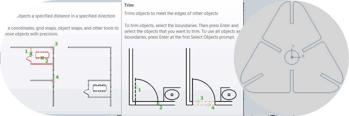
- Design, lasercut, and document a parametric press-fit construction kit, which can be assembled in multiple ways. Account for the lasercutter kerf.
- Cut something on the vinylcutter.
Software
Download File
02
Assignments
Group Assignments (1)
Characterize your lasercutter's focus, power, speed, rate, kerf, and joint clearance.
Document your work (individually or in group).
The assignment consists of visualizing and taking all possible data and possible specifications about the machine that we will use for laser cutting. In this case we will use the model that measures:
- Size of the machine: (1,830 mm x 1,500 mm x 1,200 mm).
- Area of cut (1,230 mm x 900 mm) or 1,107 m2.
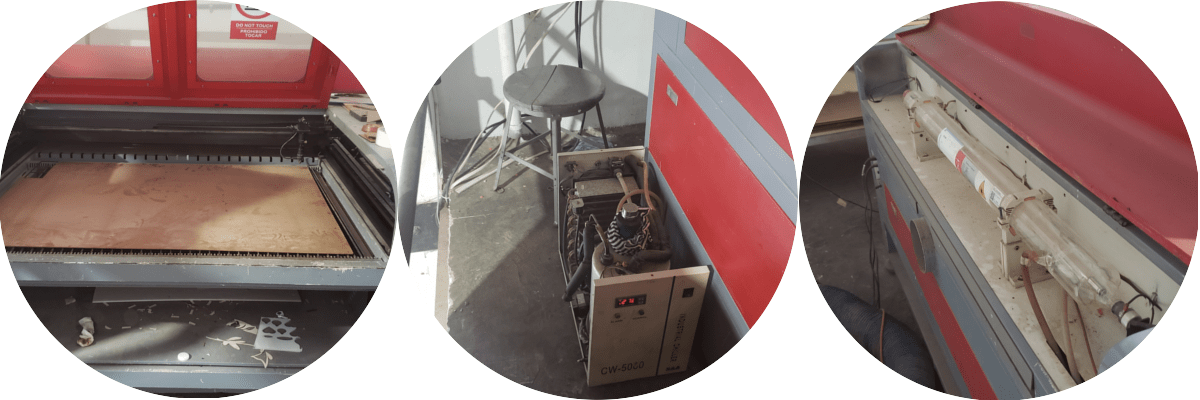
This equipment has 3 main buttons that are in the right side art, of which the first turns on the equipment, the second the tray and the third the CO2 system.
The equipment uses a CO2 tube cooling system that generates 10 watts at 110 v. For the maintenance of the equipment oil 3-1 is used.
The equipment works through 3 convex mirrors where the beam of light generated in the CO2 tube is refracted, leaving this as a very fine or thin point in the head and which is the one that makes the cuts. This lens should have regular maintenance monthly with special alcohol.
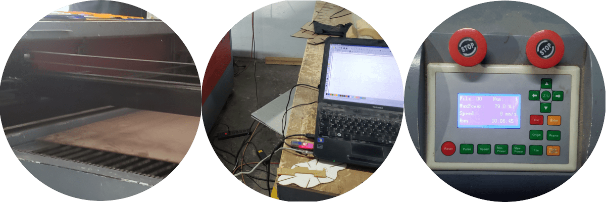
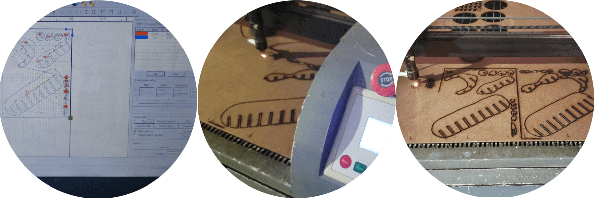
In class we could do some cutting tests on a 2 mm thick compressed cardboard, for which we took a .dxf file to the laptop that is connected to this computer.
When the computer receives the file code from the laptop, the device works with a front control panel, separated from the general ignition controllers, to locate the cut-off point, where the head and tray can be moved. The default program for cutting is Laser Work V6.
In this week of practice, the head of this equipment had to be calibrated since the diameter of the light beam was variable and did not cut all the cardboard thickness.
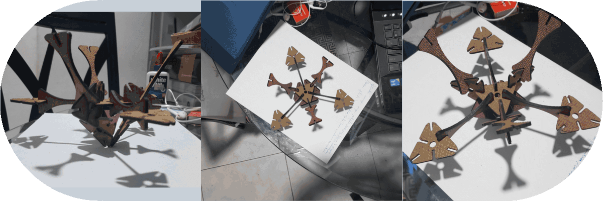
As a work, I have the idea of replicating a Thinkgeverse 3D file on Mother's Day (.stl). This file or model was taken to Slicer (previously downloaded and installed) for Fusion 360. It played a bit with the software parameters.
Slicer for Fusion 360 was downloaded from Autodesk.com and the steps for its installation were followed through the Autodesk account by installing Desktop connection.
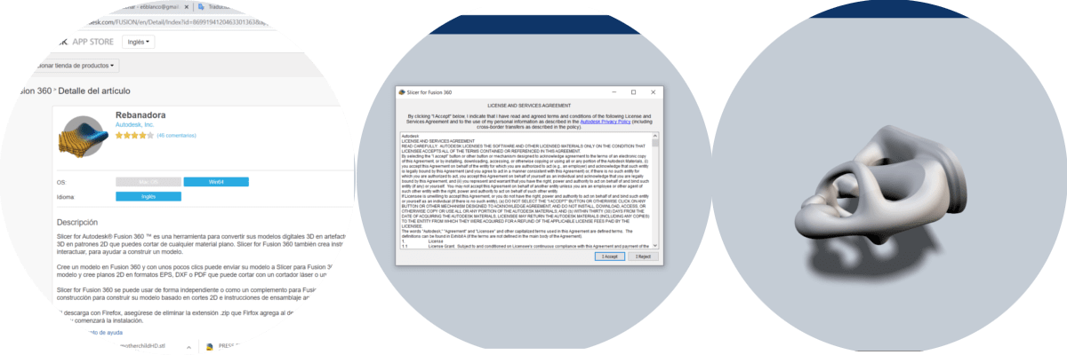
In Slicer, the .stl file was imported and the project insertion axis was given, in this case Y and the model was turned for which the steps were repeated and this time the Z axis was used.

In construction technic one of the 6 default options was selected and the parameters were adjusted to discresion. We proceeded to visualize the sketch and obtain the cutting planes to work on the laser machine.


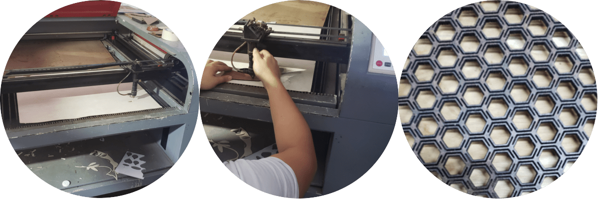
We proceeded to save the project and generate the respective plans to take to the laser. Once the cuts were made in 3 mm compressed cardboard, the pieces were assembled, according to the drawings.
After having made all the cuts of the cardboard, he proceeded to assemble the pieces as if it were a puzzle, which took time, but it was worth it.
Individual Assignments (2)
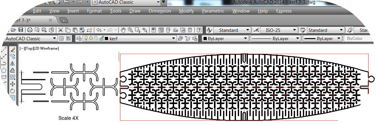
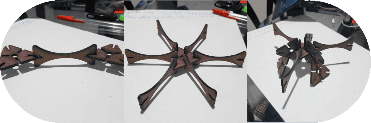
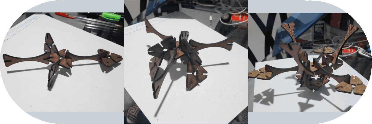
Design, lasercut, and document a parametric press-fit construction kit, which can be assembled in multiple ways. Account for the lasercutter kerf.
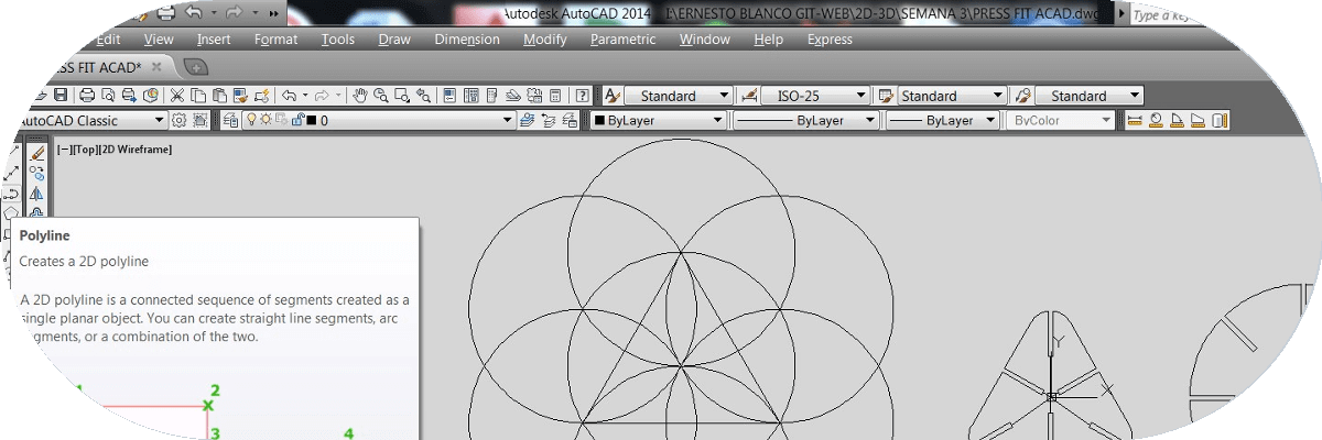
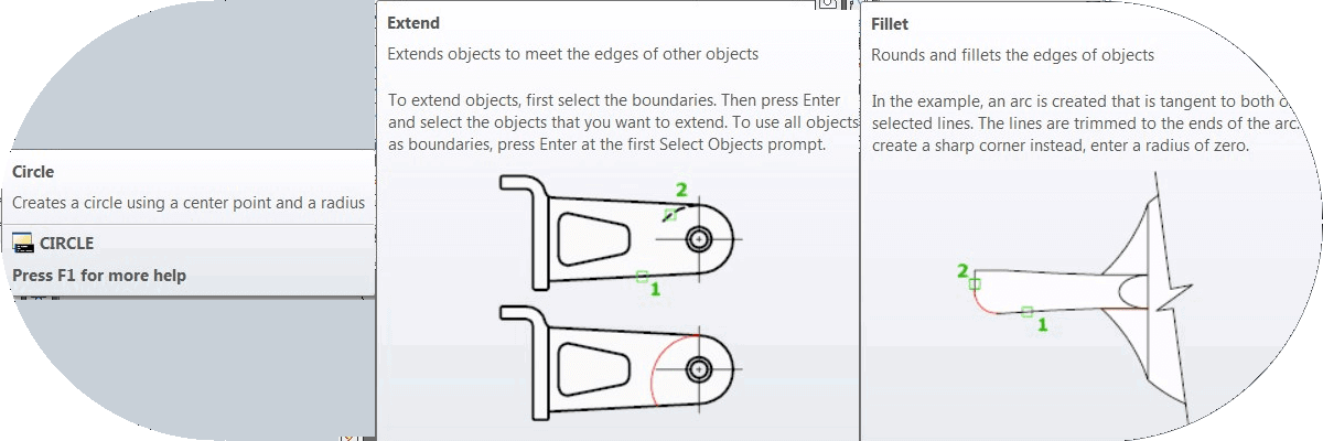
Most of the assignment started with freehand sketches and was then drawn and finished parametrically designed in AutoCAD.


Cut something on the vinylcutter.
In this section we are using a Silhouette Cameo 3 printer to perform this vinyl cutting activity. This equipment works with its own file recognition software in formats: .gsd, .studio, dxf, .png, .jpeg, .bmp, .gif, .tiff.
This cutting technique is very simple to perform, except for the design of what we want to cut or print, it is done through a knife. The equipment we use is designed to make engraving by means of special colored pilots. Both cuts and engravings can be made on different types of materials.
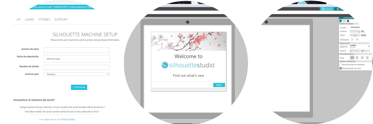
Install the Silhouette Studio 4.1 (Basic Edition) program of my tutor, since I was asked for a code from the web, during the installation you must follow the requested steps and even ask if it is the first time you use the program to install additional libraries.
The cutting of the material, is performed by a blade that works by adjusting automatically or manually, for which it is necessary to perform some tests to calibrate the depth of cut according to the material to be used according to the manufacturer.
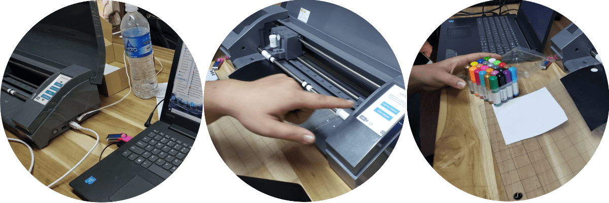
For my first attempt at printing, manually cut a section of vinyl and place it on the pad and present it on the base of the printer, placing it on the computer panel and adjusting some parameters for the printer to take the pad.
At the beginning of the printing or cutting, I did not do it because the insurance of the equipment was not in place, once I realized this situation I proceeded to correct this error and proceeded to do some cutting tests, you can also sketch with pilots special colors, at the same time the cut is made.
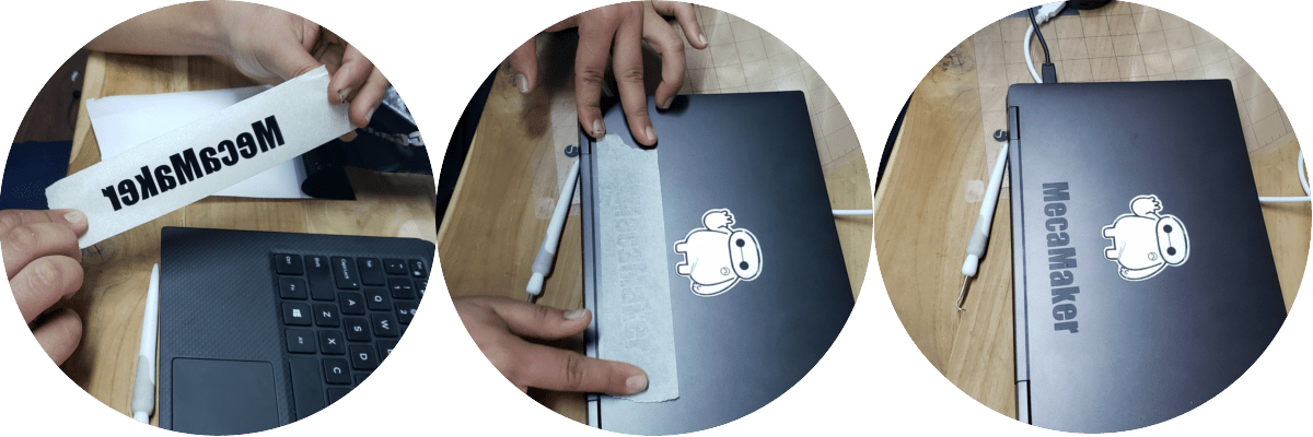
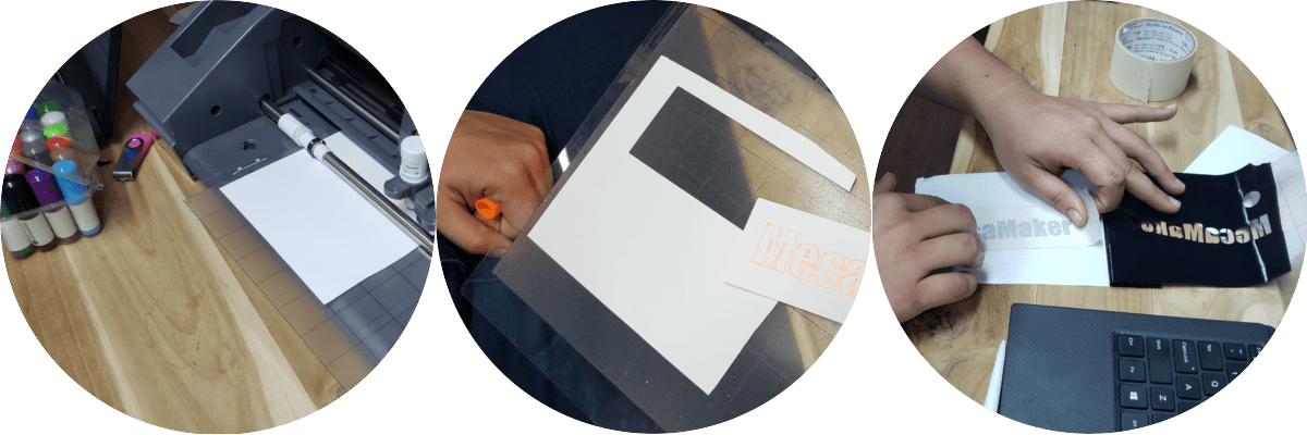
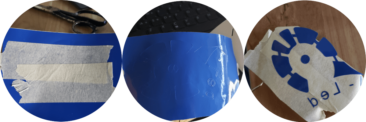
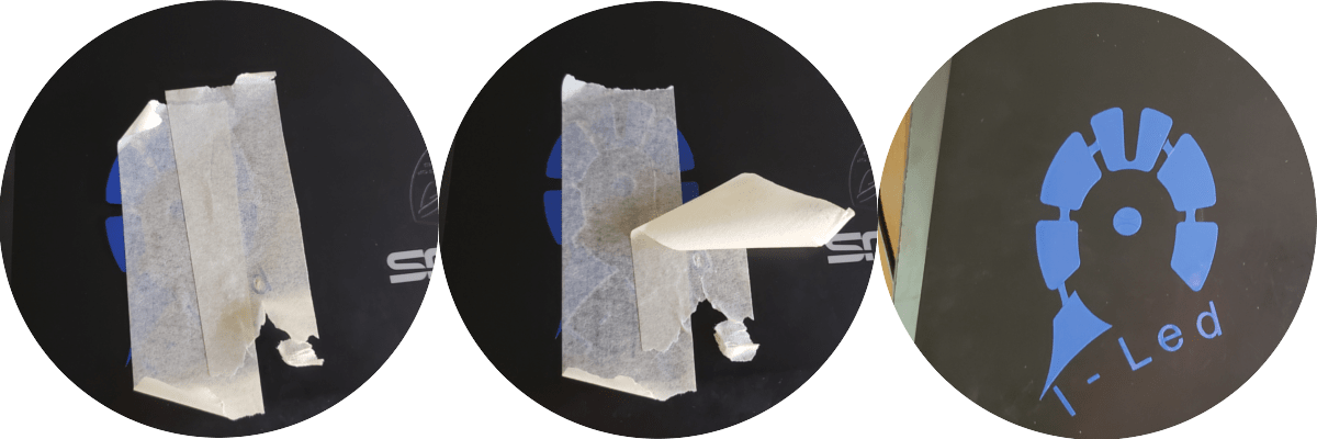
And now my litmus test..., in this, like the previous one, a tape had to be used on the front of the print to fix the product to the laptop and then remove the tape...
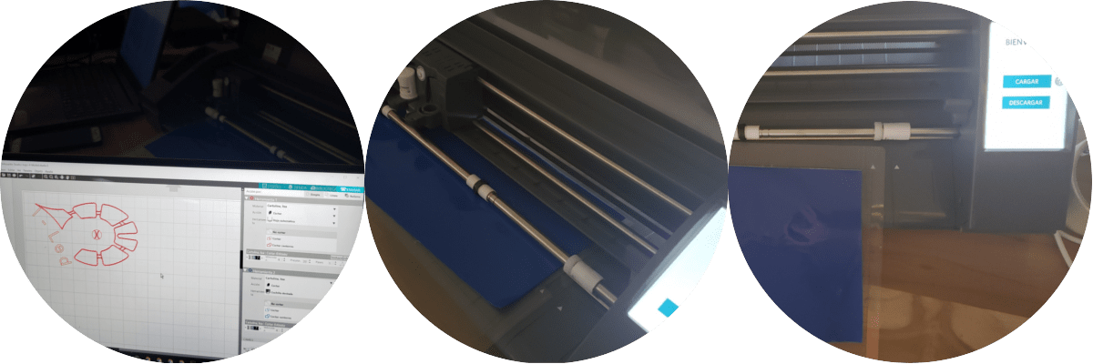
Before sending the file to the equipment, the protector of the self-adhesive pad must be removed to place the piece of vinyl, once this step is ready, the pad is placed in the machine and aligned with two predefined edges. After this, the loading tab on the device is touched and the cutting file is sent, the machine performs a calibration and the actual cutting work begins.
For the design I decided to make a logo of the final project that was something similar in shape to this, for which I made a freehand sketch and I went to draw in AutoCAD working in mm, this file I saved as a .dxf that was taken to the Silhouette Cameo 3. At this point you have to place the depth and speed parameters, you had the opportunity to see someone using the equipment and put the depth at 8, the speed at 5, the pressure at 10 and the amount of you pass in one, but the blade cuts the pad measuring 12 "x12" and for this reason my depth setting was set at 6.
Inconveniences - Delays
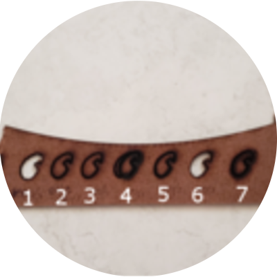
Several tests were carried out with different parameters of power and speed, however the result was not spacing, although with some of them it was noted that the cut went through the cardboard.
It was not until a long time after a scolding, the height of the laser tip was set at about 10 mm height of the cardboard and everything was fine from there.
After all, we find that the correct parameters for this type of material are:
- Power: 70.
- Spedd: 8.
- Height to piece or cardboard: 10 mm
Another thing that confused me at the beginning is the fact that the conduit that brings air to the nozzle of the cutter was loose (burned) and left its position which caused that it had to be aware of this situation so that the air pressure When leaving the tube of the conduit it will not create a flame that could cause an accident.