Week 11
Output Devices
01
Assignments
- Group assignment.
- Measure the power consumption of an output device.
- Document your work (in a group or individually).
- Individual assignments
- Add an output device to a microcontroller board you've designed and program it to do something.
Software
Download File
Resource
02
Assignments
Group Assignments (1)
-
Measure the power consumption of an output device.
-
Document your work (in a group or individually).
We have not yet been able to access the FabLab, nor the corresponding equipment to carry out the physical practices, which in my case are very necessary since it is not the same as simulating situations with characteristics given by default.
We have not yet been able to access the FabLab, nor the corresponding equipment to carry out the physical practices, which in my case are very necessary since it is not the same as simulating situations with characteristics given by default.
Individual Assignments (2)
Add an output device to a microcontroller board you've designed and program it to do something
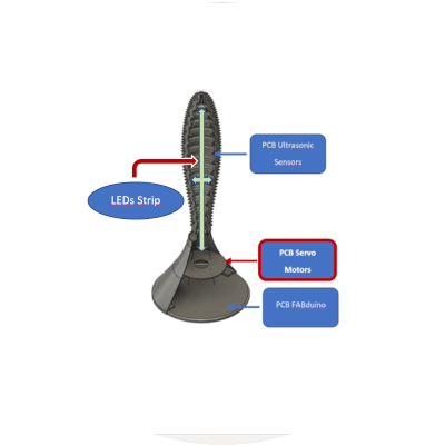
To familiarize yourself with the development of this week's assignments, please refer to Week 4 (Electronics Production) and Week 6 (Electronics Design).Although in the final project it will take rgb leds strip as output components, on the inside of the prototype.
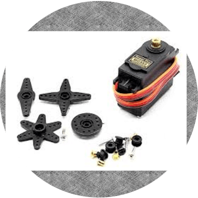
The ultimate goal of this assignment is to design and program an output device, in our case a servo motor and I will add an ultrasonic sensor to it because I am preparing for my final project where the sensor can make the servo move.
For a couple of weeks with my instructor we were seeing the different types of servo motors that exist and we decided to use the model with metal gears MG995 however, in this do not pay attention due to the stop angle in which it moves, until this week where I discovered that it can only move 90 degrees in each direction, which at this moment I don't know if it will be enough. On the contrary, since they were sent to buy and have not yet arrived at the FAbLab, I am planning to design and manufacture in 3D a part that can be adapted to the servo to function as a reel (fishing rod), to increase the angle of work of the servo.
All this is pending due to the total quarantine based on COVID-19, so I have to wait to advance in one way or another.
- Connector Cable Length: 11.811 in.
- Operating speed: 0.17 seconds / 60 degrees (4.8V no load).
- Operating speed: 0.13 seconds / 60 degrees (6.0V no load).
- Foot screw: 26.5 lbs / cm (6V), 28.7 lbs / cm (7.2 V)
- Operating voltage: 3.0 V - 7.2 V.
- Gear type: all metal gears.
- Deadband Width: 4.
- Plug Specifications: JR FUTABA and so on.
- Temperature range: -30 - + 60 degrees
- Item size: 1,602 x 0.776 x 1,689 in.
- Servo Weight: 1.94 oz.
Control Specifications:
- Control method: PWM.
- Pulse width: 500-2500
- Service ratio: 0.5 ms-2.5 ms.
- Pulse time: 20 ms.
Connection:
- Red wire: +
- Yellow wire: PWM / Signal
- Brown wire: GND.
Based on what was published in week 9, in truth, the interesting and complex is becoming fascinating, since you can start to see the operation of each week applied to the final project and, as in the week mentioned above, I look for my project is more practical and safe; taking the decision to create a shield to serve as a mid-level floating base, separate from the Fabduino, due to the design and modeling of the prototype and for reasons of maintenance, repair, assembly and observation of the operation; the arrangement of this is much easier.
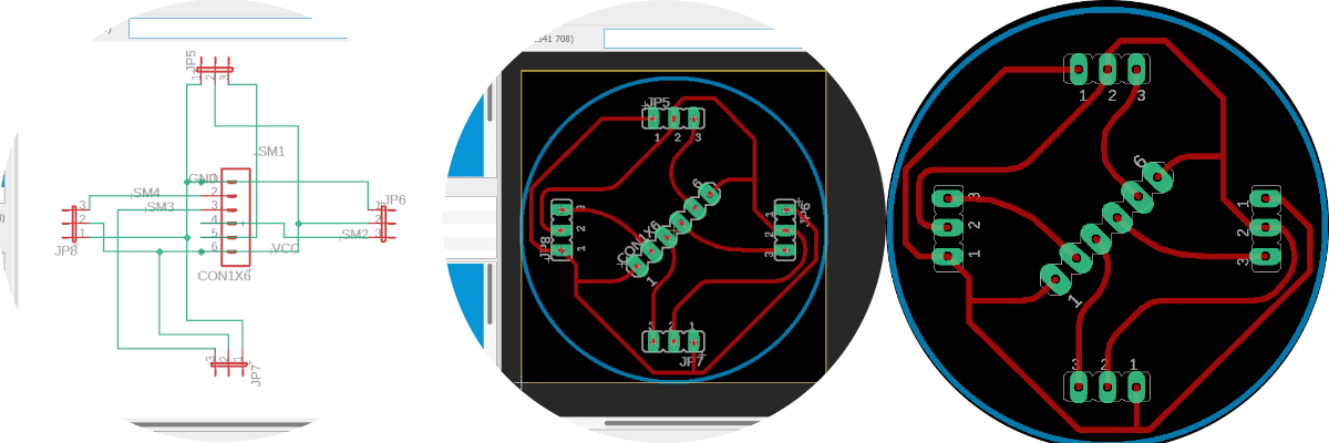
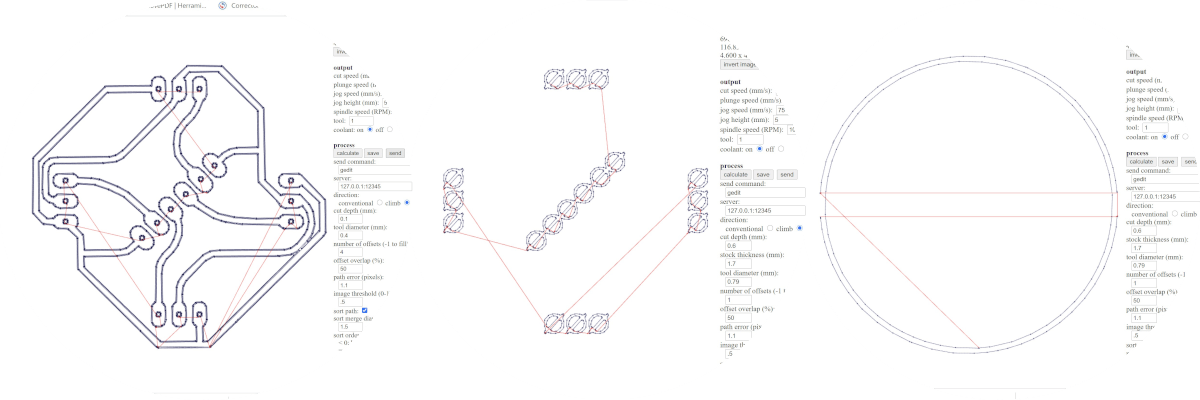
Based on the above and describing this section of the final project, it will have a PCB at an intermediate level and will contain the 4 servo motors with their respective male and female adaptation jumpers. Also in this space we can appreciate the location of the led lights.

As soon as it is reliable and safe, depending on what the authorities of the Ministry of Health say; It is in the capacity to manufacture these elements and physically fulfill the assignments.
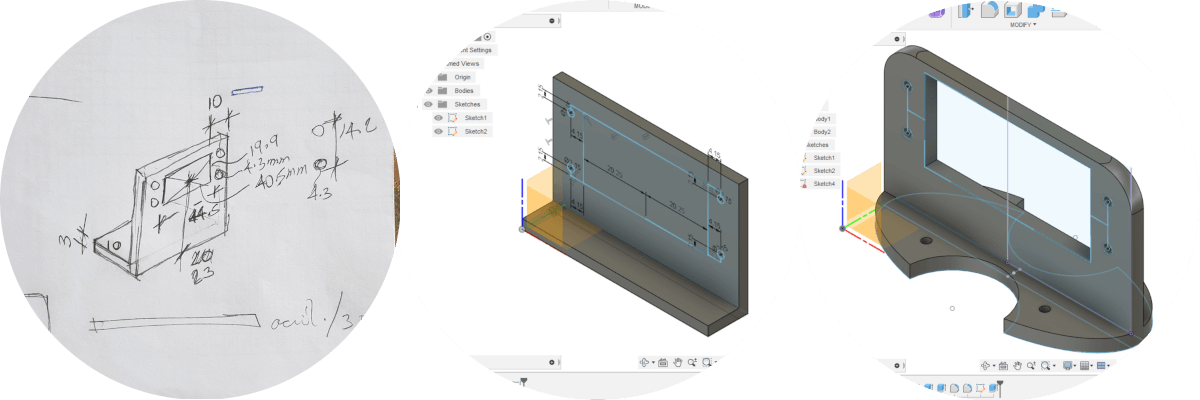
At this stage and continuing with the final project also taking as reference to separate the installation of the components and their pcb by levels, I have designed an adapter so that they can hold the servo motors in disposition of the cardinal points, since their individual functions of pulling threads to make the lamp bend is a sequence between them and for this same reason they must be separated from the holding floor and in a horizontal position for the mechanism to work.
The base will be bolted to a horizontal piece and each servo will be bolted to the base as an anchoring method.
Inconveniences - Delays
We have not yet been able to access the FabLab, nor the corresponding equipment to carry out the physical practices, which in my case are very necessary since it is not the same as simulating situations with characteristics given by default.
As soon as it is reliable and safe, depending on what the authorities of the Ministry of Health say; It is in the capacity to manufacture these elements and physically fulfill the assignments.