This week we are about week one-ish of shelter in place. Currently my team is spread across the world. Zina is in Bhutan, Martina is in Milan, and Spencer is in Massachusets. While I currenlty live in Boston, my partner (and dog) and I decided to head down south to stay with my parents. At this point I am helping local efforts to make PPE for our doctors and nurses. For now, I am using the kit my instructors sent me and it has an arduino and alot of input and output devices. Hopefully when I get back to the lab, I will be able to jump back into my finaly project.
Where do I start?
So I immediatley began hoping I could do something kinetic. I have a 3d Printer I borrowed from work and I think it'd be fun to make a component to attach to the motor in my kit. I found this tutorial and tried to follow it. I got everything set up but there were errors in the code and it wouldn't go onto the Arduino. Then I decided I may be getting ahead of myself and looked for a more basic tutorial which I found on Adafruit's site. I realize in a normal year this would'nt be the equivalent of doing the homework... but for now this is better than nothing! I am also just beginning learning the Eagle software. For now, I will begin to learn Arduino IDE and how to use some of the pieces in my kit.
Trivia Slideshow (press arrow)
What is a breadboard?
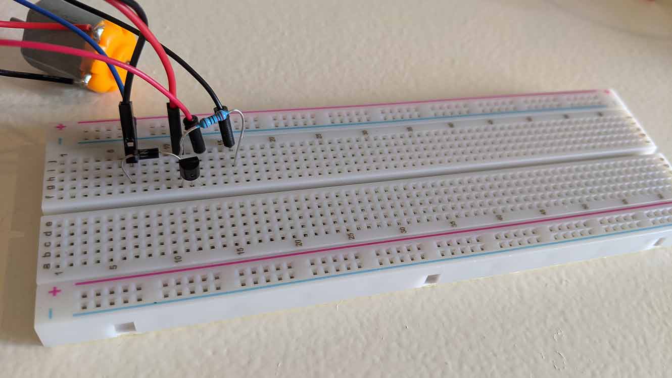
A breadboard is a way to connect electronic components without needing to solder them.
What is...this?
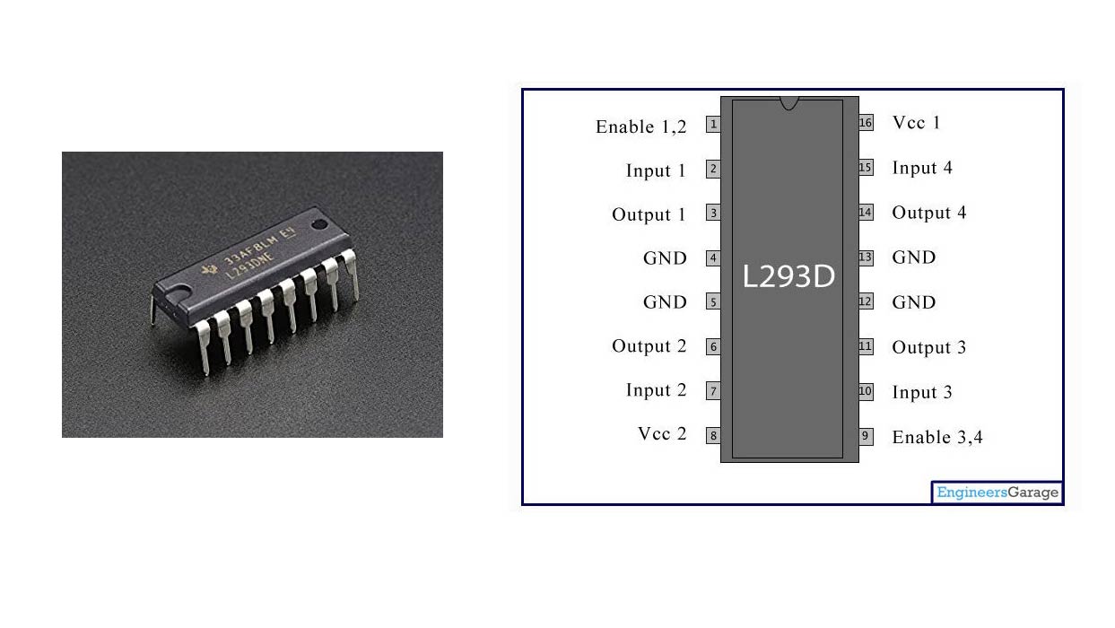
For our purposes, we will use this as a motor control chip. This one is an L293D IC.
What is resistance?
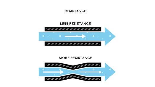
Resistance is kind of like how much water can get through the tube... or how much charge can go through something at once. This brings us to Georg Ohm's Law called Ohm's Law. In equations, Ohms looks like the Lululemon logo, Ω. Voltage = Current x Resistance
What are resistors?
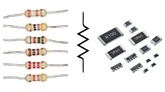
This is what some resistors look like. There are lots of different kinds of resistors. We use SMD (surface mounted devices) resistors. Different kinds of resistors have different ways of knowing what they are. This guide helped me better understand the ones we have been using in FabAcademy. Also the zig zag line is how they look in some diagrams.
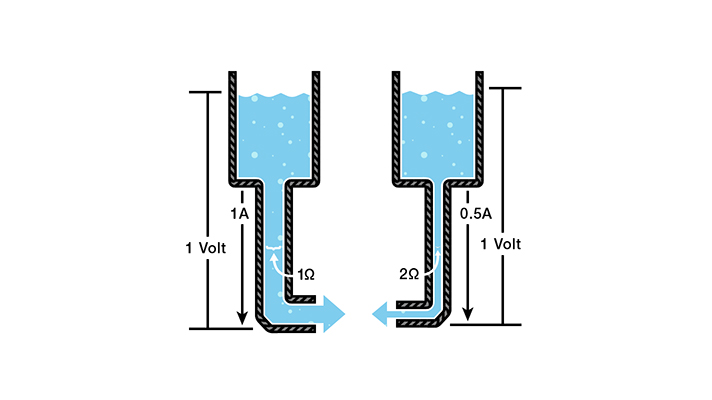
Ohm's?
V = Voltage in volts, I = Current in amps, R = Resistance in ohms
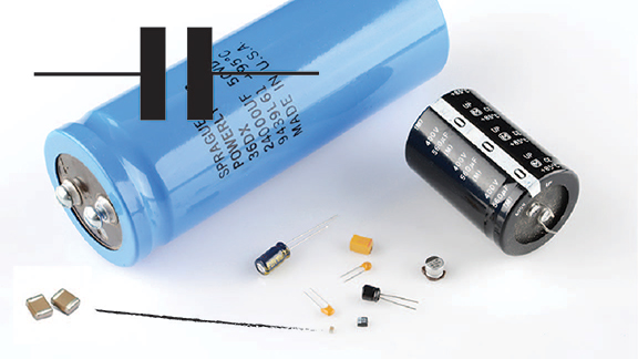
Capacitors?
The basic function of a capacitor is to store electrical energy. Essentially, potential difference is created and that translates into energy until it is balanced out. When you add electrical energy to a capacitor is is called charging and when you release it it's called discharging. We measure capacitance using farads.
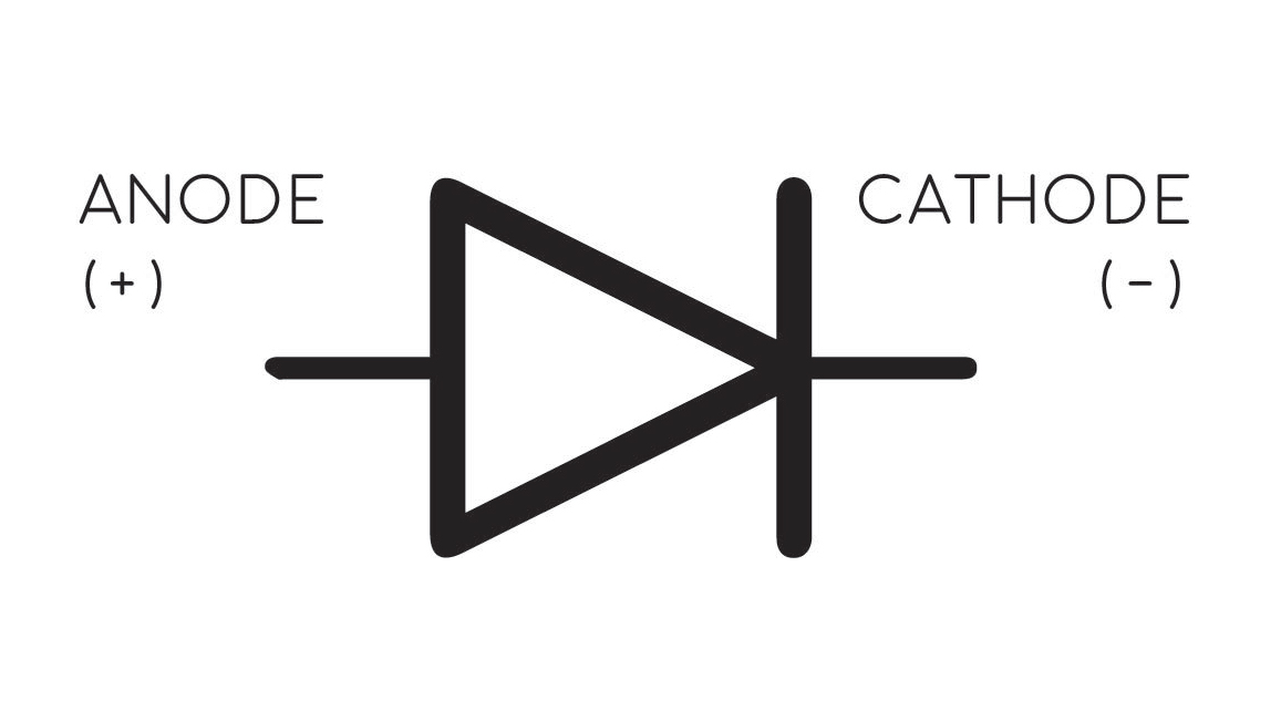
What are diodes?
Diodes have two terminals and they are distinctly polarized. Diodes kind of help current go the way we want it to I think...? LEDs are light emitting diodes.
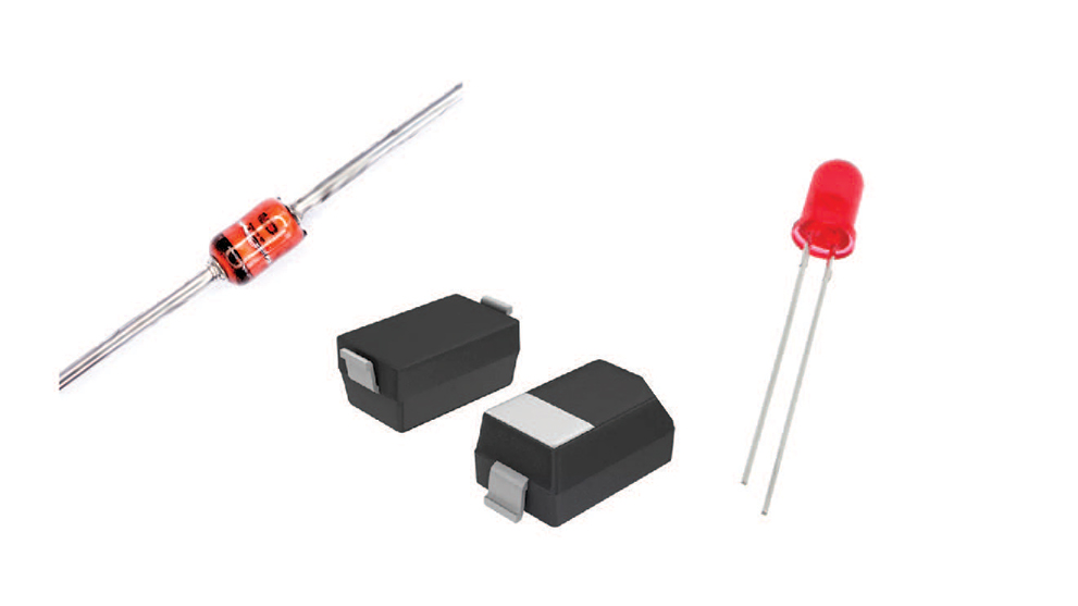
Zener diodes and LEDs..?
For the ATtiny we did last week, we used two zener diodes and two LEDs.
Blink
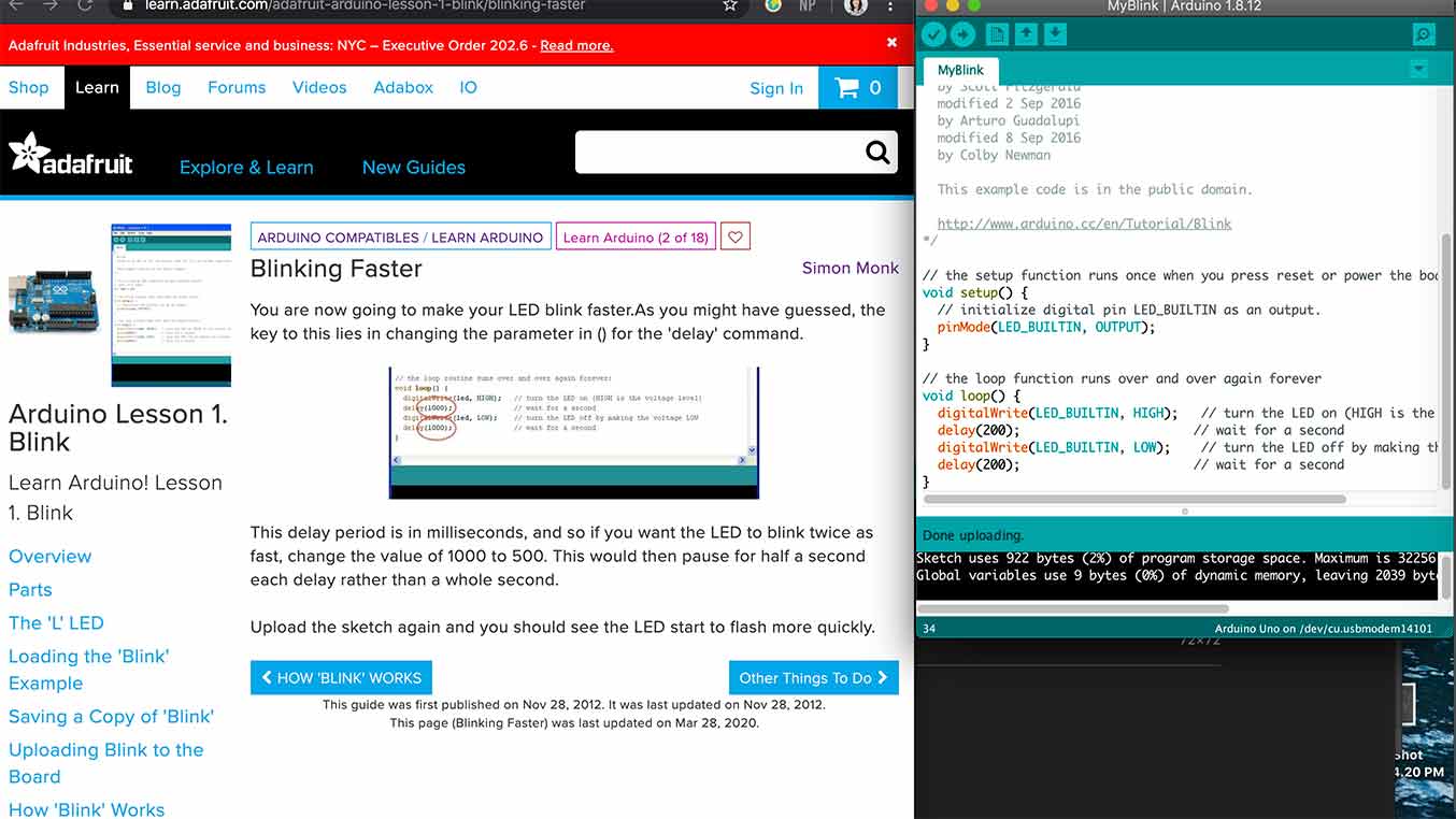
In this exercise I got the Arduino LED to blink and I added an LED to my breadboard and got it to blink.
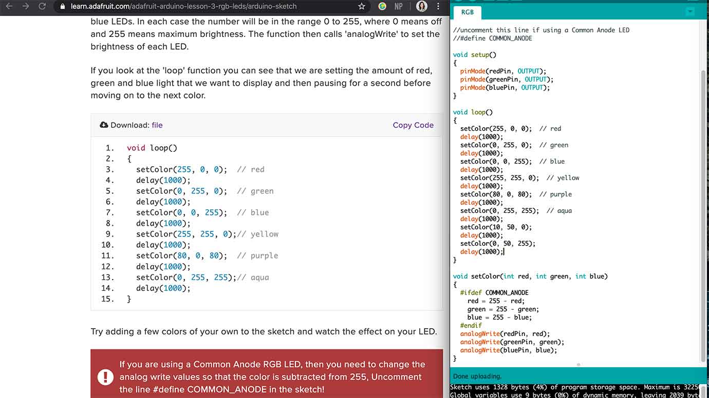
RGB LEDs
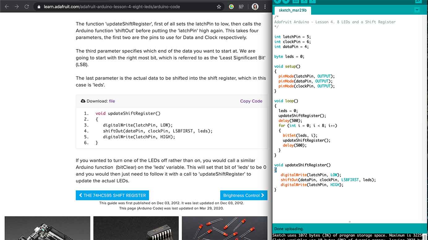
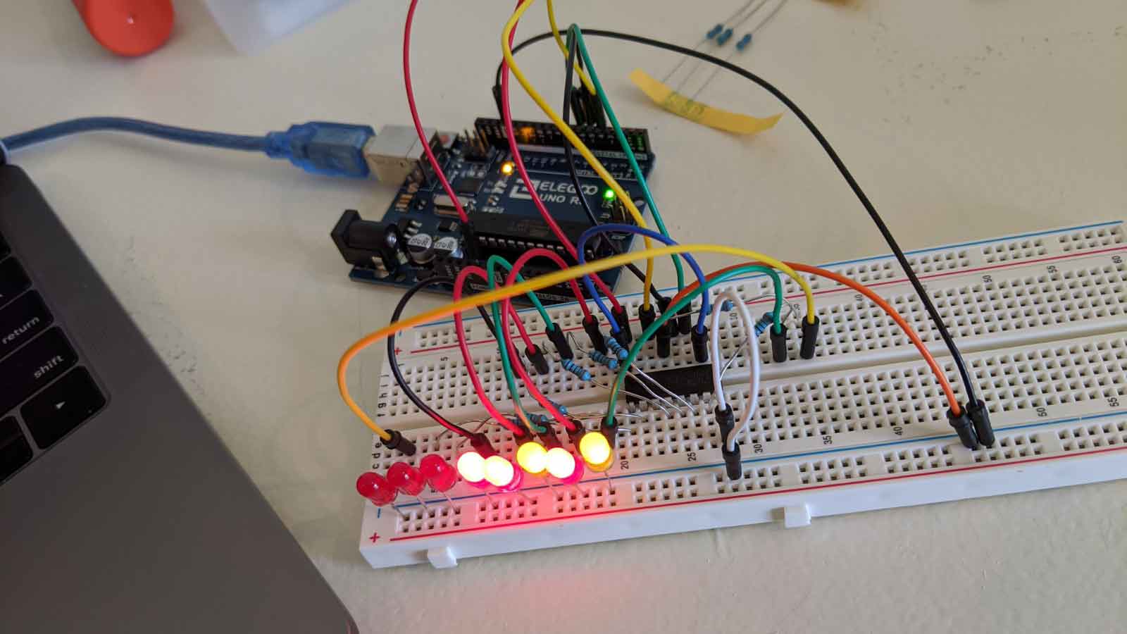
8 LEDs
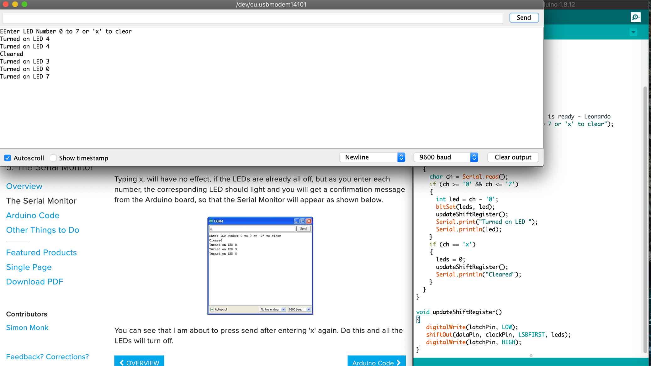
Serial Monitor
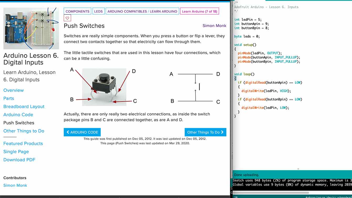
Digital Inputs
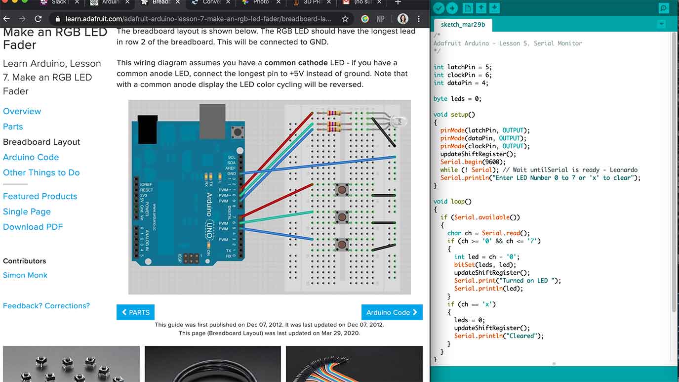
RGB LED Fader
AHHH!!!
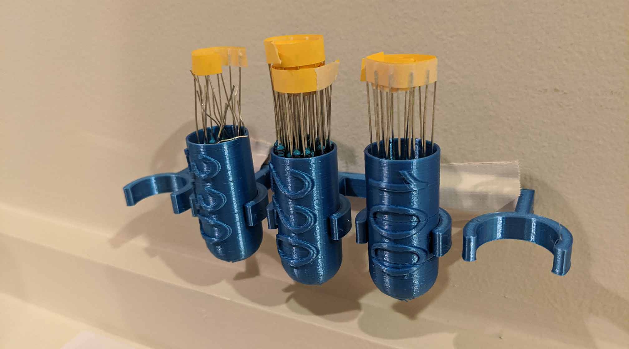
I was pretty frustrated having to squint my eyes and remember which resistor I had picked up so I decided to distract myself and make an organization system... it was fun to learn how to put text on the rounded surface in Fusion 360.
Making Sounds
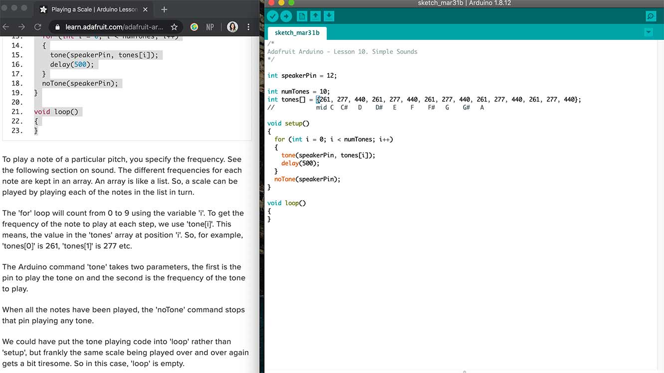
The command 'tone' has two parameters, first is the pin to play the tone on and the second is the frequency of the tone to play. This was a string of notes not on loop. Kind of fun.
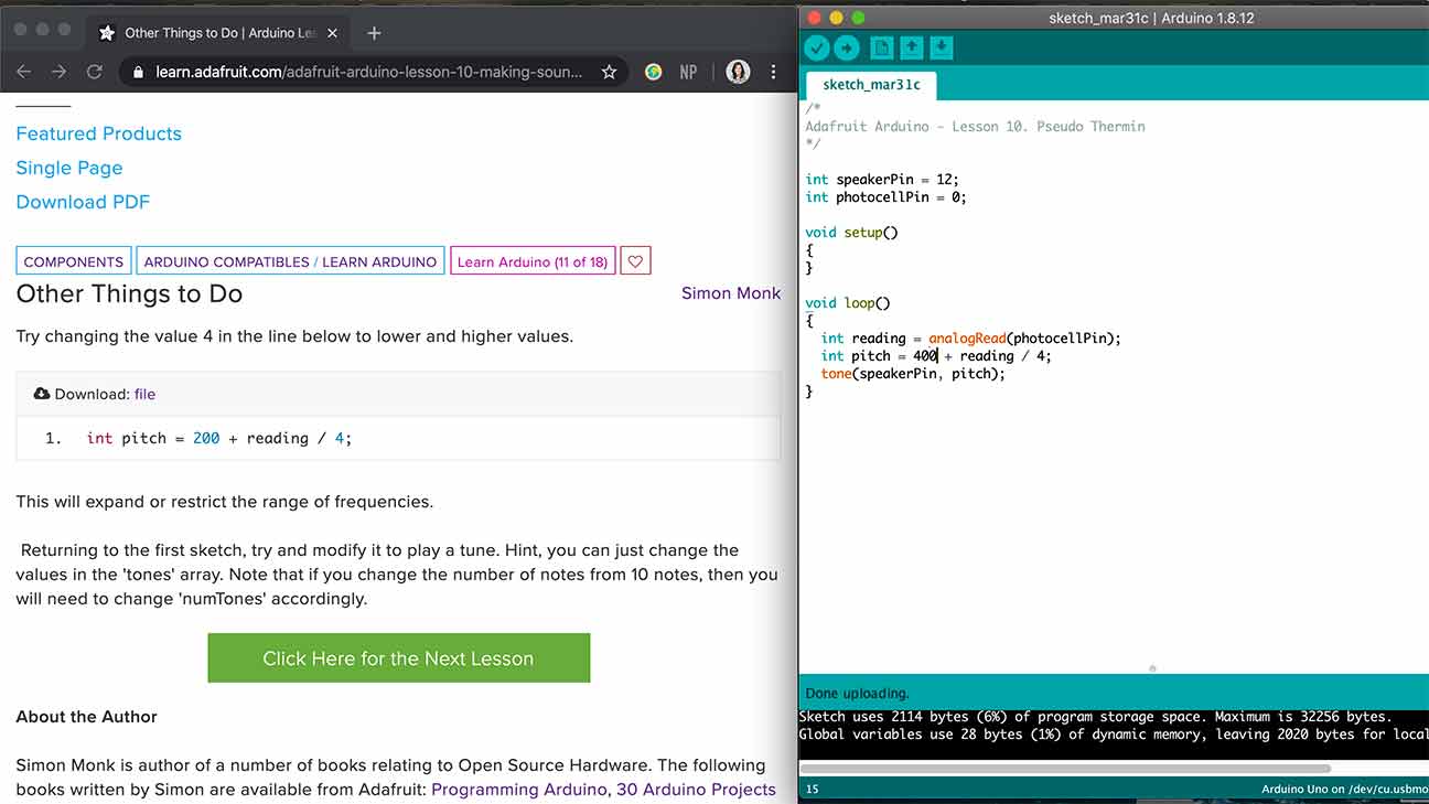
This uses a Photocell (Light Dependent Resistor) and the note changed based on the light input. I think...?
Motor
Song
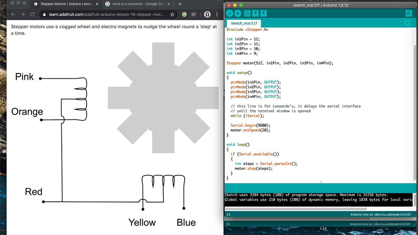
Stepper Motor
Back to the lab
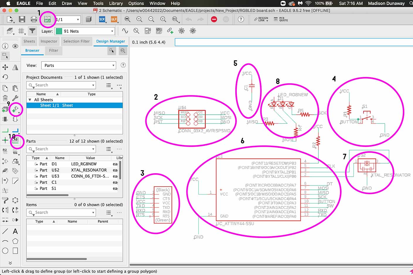
Let's go over some Eagle stuff for my own sake.
- This is how you switch back and forth between the board and the schematic.
- This is the ISP connector which is how you will initially program your board.
- This is the 6 pin header.
- This is the button.
- This is a capacitor.
- ATTiny44
- Crystal Resonator
- RGB LED
- How to add a part
- How to label and therefore connect a part.
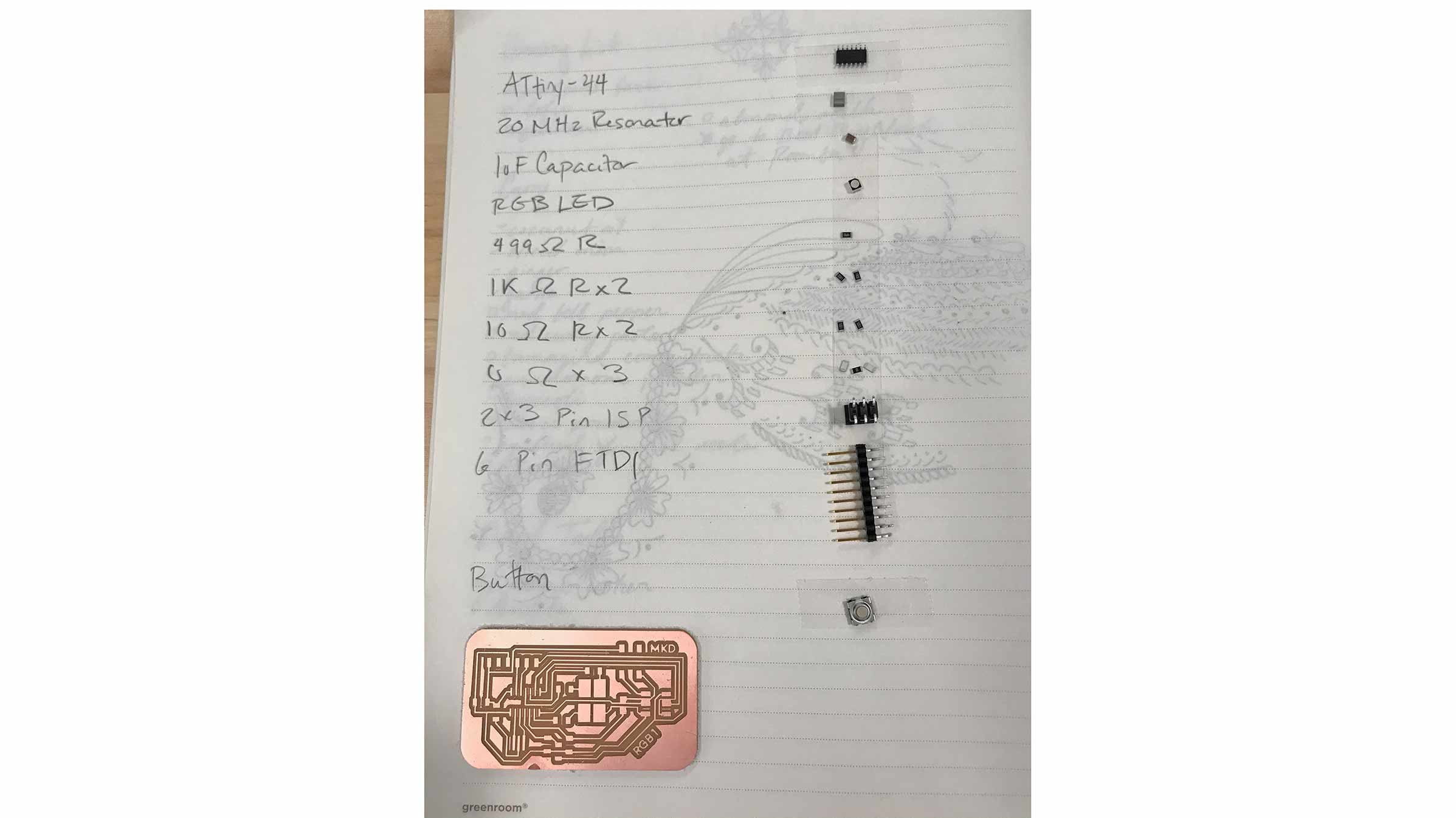
These are the parts needed. Pro tip: if you use double sided tape, they adhere to your parts list and your less likely to loose them when you start soldering or moving around.
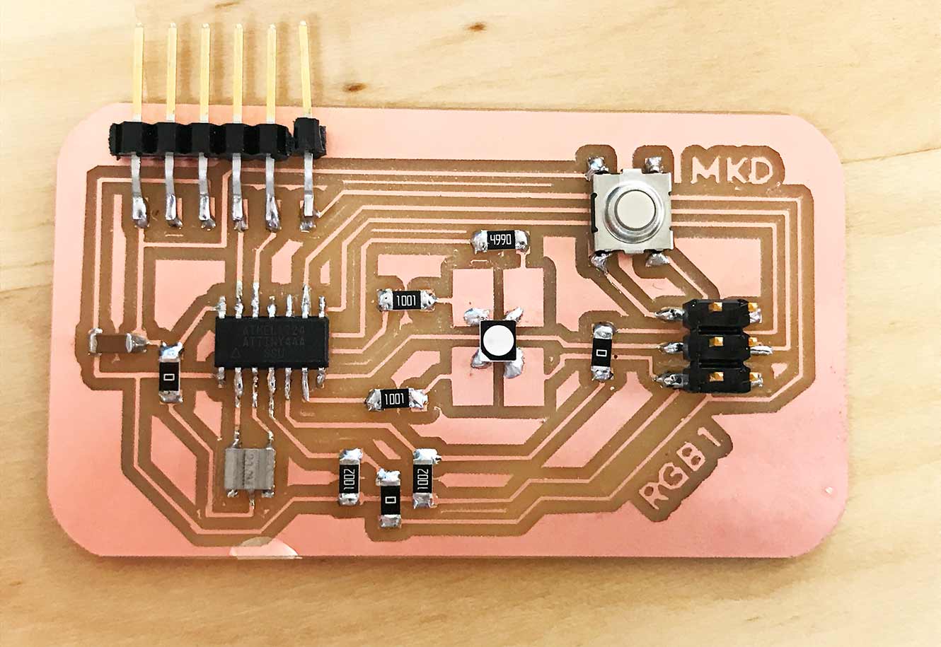
This is the board finally soldered!
For more information on insight about input and my later findings on input as a rotary encoder and output as neopixels, please see my findings here.