Week15:Molding and casting
group assignment
review the safety data sheets for each of your molding and casting materials, then make and compare test casts with each of them.
individual assignment
design a mold around the stock and tooling that you'll be using, mill it (rough cut + (at least) three-axis finish cut), and use it to cast parts.
group assignemnt
From here you can visit my page on the lab of México city to check the Group assignmen on this week
indivivual assignemnt
this week was really tough for me 'cause i'm not use to think in terms of molding and casting as a manufacture process.
I'm an engineer and i knew just a little about the molding and casting process in industrial enviroments but as a mechanical designer i never had quite the oportunity to make a mold for one of my designs.
tough i've used Solidworks software since 2016 i've never had the necesity to use all of the "mold tools" embeded in solidworks. so i have to watch a lot of tutorials on youtube to achive this challenge tutorials i will be linking at the end of this page under references.
So, let's dig a little into the process i did this week to develop the mold for the positive and negative pieces.
The Original model
For my final project called "Smart curing station" which you can visit here i needed to attach metal geared 12v motor which is an old model from jameco
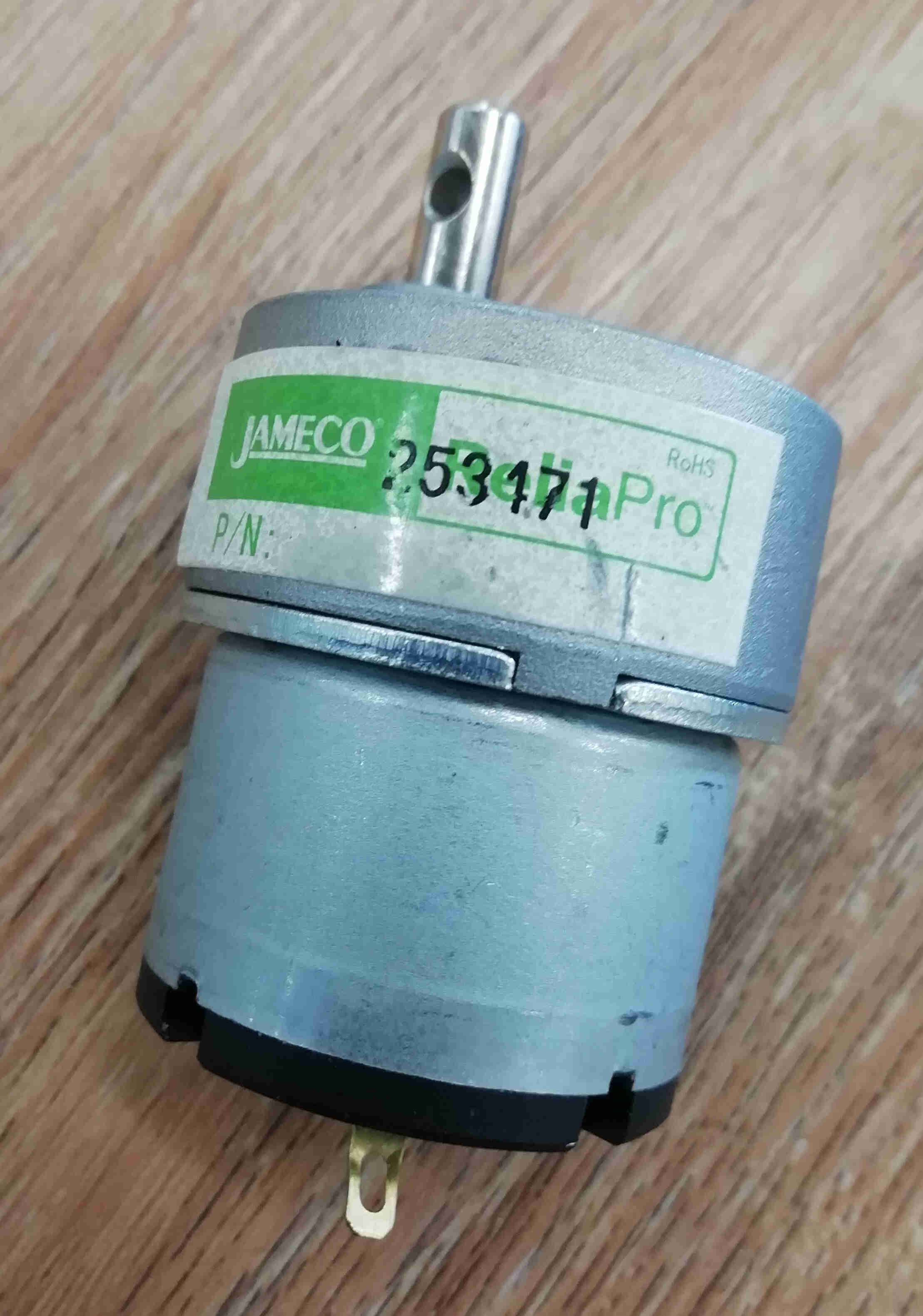 picture of the phisical motor
but in order to see wether i could fit it inside the electronics compartment i had to make a 3D model out of it so i went to jameco web page to download some of the 2D CAD dimension to really make a high fidelity 3D model.
but i could not find the model on the picture above.
So i took and old vernier caliper that i had around from when i was at college and compare my measurements with an updated version of my old model and i found that the phisical dimension were excactly the same as the dimension on the CAD of the new model.
you can download the cad from here but i most warn you that you should not expect the electrical specs to be the same as the old model.
So, now i had what i needed to make a 3D model.
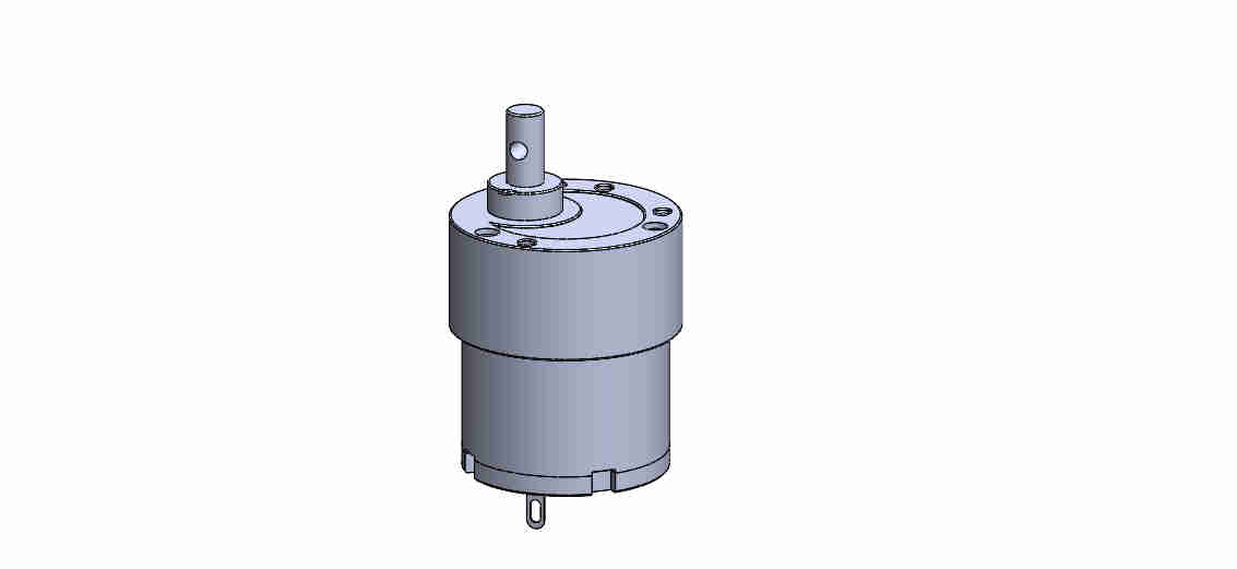 Screenshot of the 3D model of the motor
If you need the actual model of i made is in the references section at the end of this page.
Now, i had to include the 3D model on my motor in my draft of the final project.
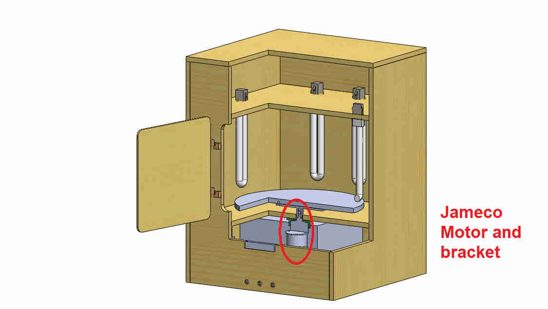 screenshot of the final project assembled and in section view.
Now i could see on solidwors that i could fit into the whole machine this kind of motor: But i need a way to fix it to the frame so could spin a little table were i need to place a piece of 3D printed part from our Form 2 in our Lab.
So, i went ahead and model a piece to fix the motor in place to the frame of the curing station.
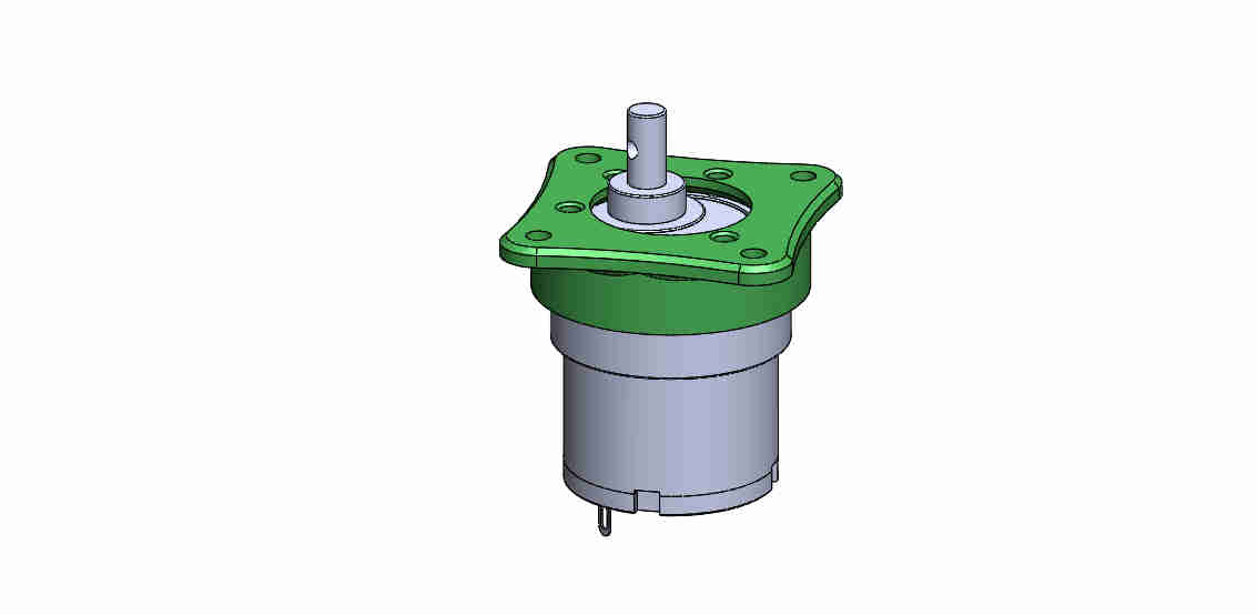 picture of the bracket fixed to the motor.
if you want to test the piece for yourself you can download the files at the end of this page on the references section.
The Mold process
Each time i had to draw a piece in solidworks i start ussually sketching on a piece of paper to set some ideas of the geometries that i need on the final 3D model.
like this time a had not enough information to work aside the 3D model i've just made i used a cross section view to sketch on paper wich mold will contain which face features.
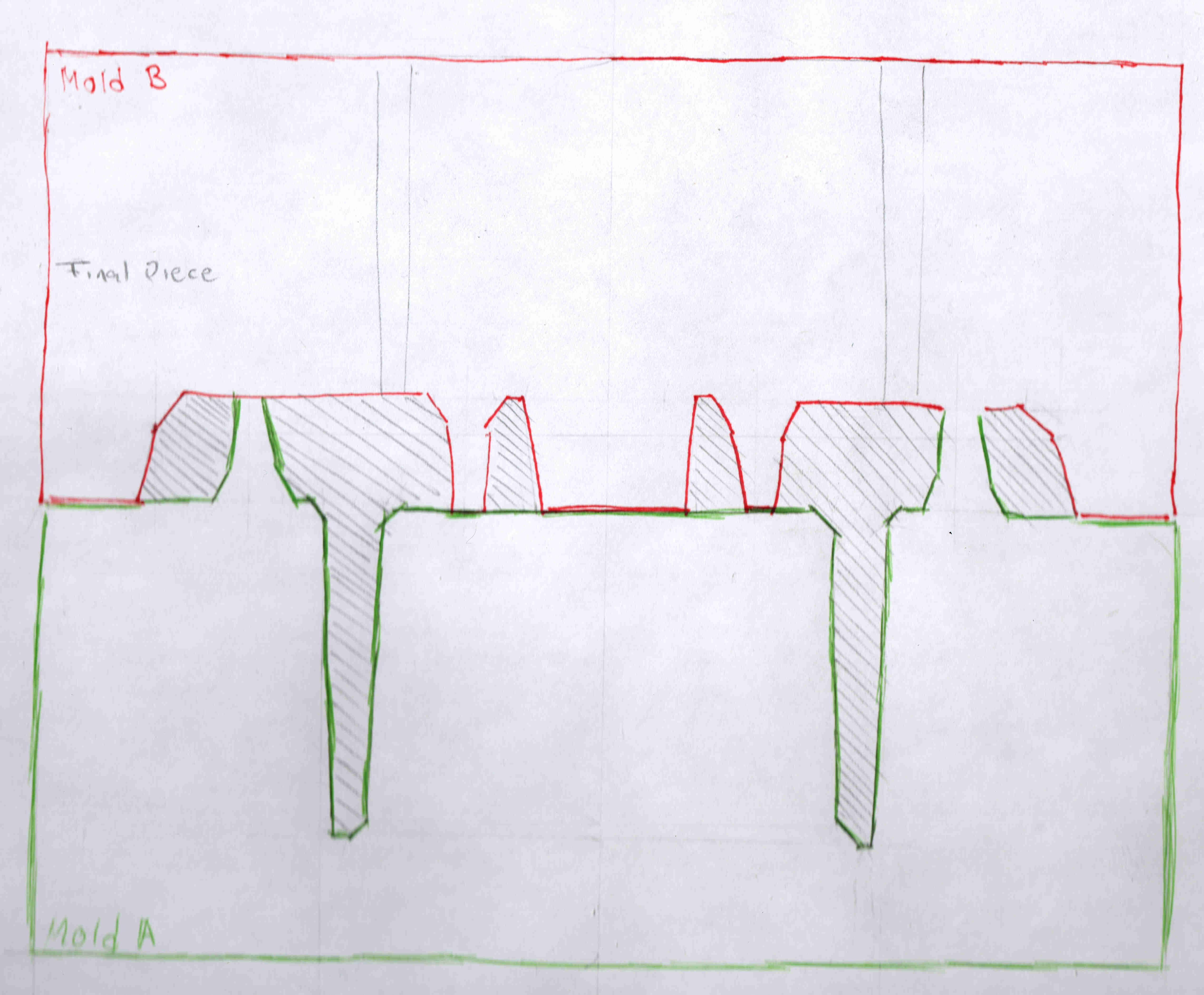 Hand-made sketch on the mold features.
now in order to keep this nice and tiddy i will make a list of steps here to follow my work process.
now you have created what is called a "negative" of the original piece.
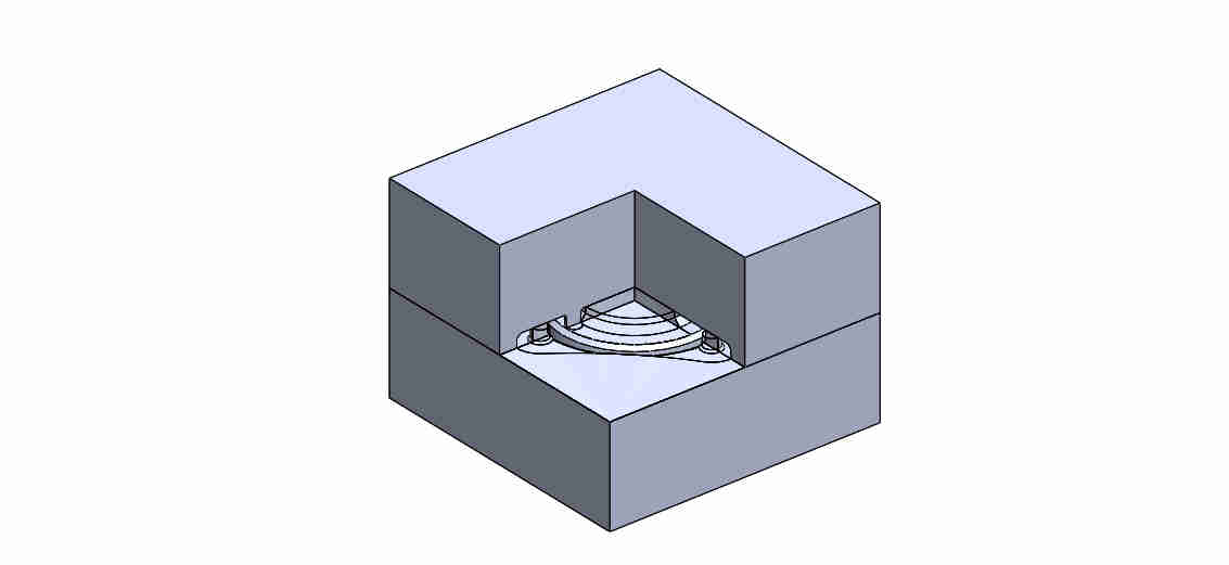 Negative mold on top of each other
Positive process
the following list is optional acording to your process but in my case i chose to mill a "positive" out of a wood piece on the SRM-20 in our lab and make the "negative in Flexible rubber" and then cast the piece on some rigid plastic.
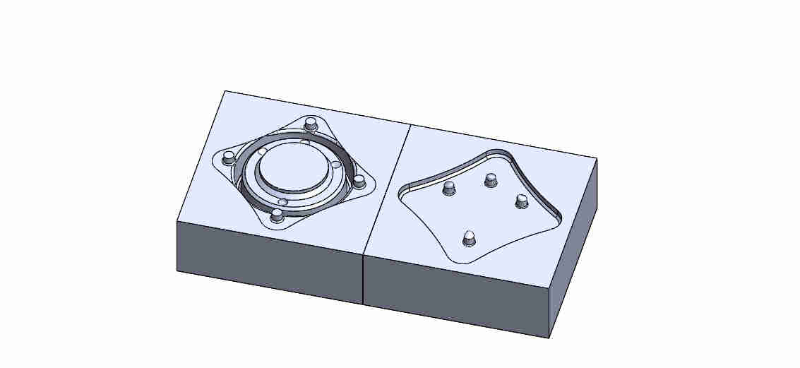
At the end of step 8 you'll end up with 2 separate solid bodies.
I fliped the top one and place it next to the bottom one on the same plane in order to make a boolean union of both solids and finally make the positive.
after step 11 you'll end up with a "positive" version of the "negative mold"
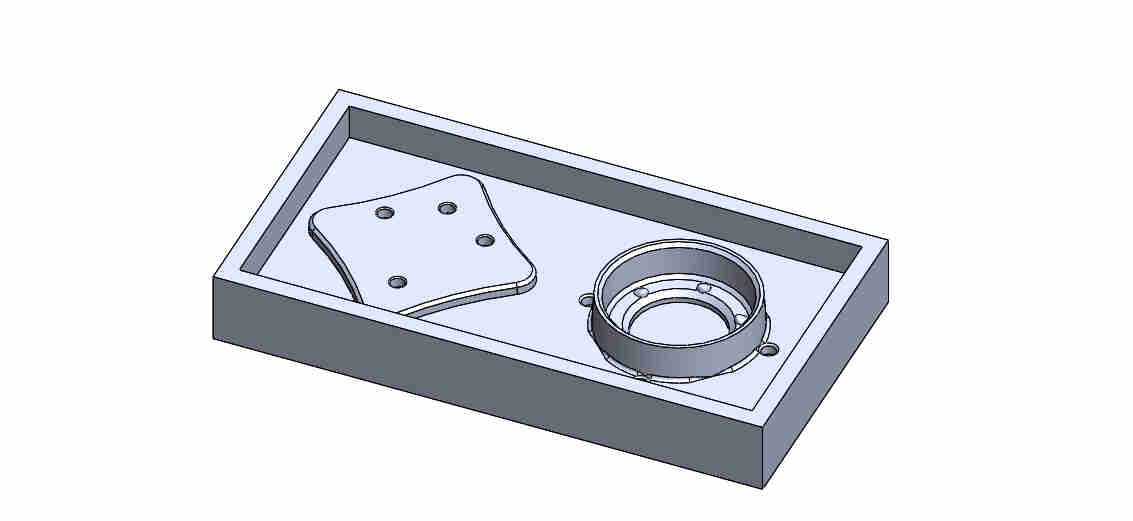
 Negative mold without the boolean union
 positive version of the negative mold
every step after this should be the preparation for the milling process.
Final toughts
Tough i'm pretty happy with the skills learned and developed this week, at this point i'm not sure if i will be able to use the piece in the final project. I fear that the scale factor i used (2%) wont work. And been forced to mill the positive all over again and then cast the negative and finally cast the piece will be to much for a piece that originally was ment to be 3D printed in PLA.
Still a work in progress
Due to the COVID-19 contingency i was not able to mill the mold yet, i will be updating this assignment when i could gather the materials and can use the machines in our lab.
I will make a tutorial on how to do this week assignment in case you could not follow the list above.
But i belive i'ts gonna be bigger than 10MB and won't be able to push it and i need to make some tutorials on "Adobe premier pro" wich is my weapon of choice when it comes to video editing (i'm not that skilled yet.)
I'll link it in the references section as well as an iFrame here so, stay tunned.
UPDATE
22/05/20
uplodaded the tutorial on toolpath generation using SRP Player from Roland. DONE
uplodaded the tutorial on Negative and positive mold generation using solidworks.DONE
uploaded the G-code generated this week.DONE
this videos are hosted in my youtube chanel because even croping the audio were heavier than 10MB so y uploaded them into youtube.
video on SRP player toolpath generation
video on molding generation using solidworks.
REFERENCES
here i will link the documents on this week assignment and tutorials i followed this week.
HERE you can download the file of the Jameco 3D model i've made (original version on solidworks 2019 and if the git gods allow it STL file).
HERE you can download the file of original piece i've made (original version on solidworks 2019 and if the git gods allow it STL file).
HERE you can download the file of the "negative" 3D model i've made (original version on solidworks 2019 and if the git gods allow it STL file).
HERE you can download the file of the "positive" 3D model i've made (original version on solidworks 2019 and if the git gods allow it STL file).
HERE you can download the G-code files i've made (hopefully will be ready after COVID-19 contingency).
HERE you can go to my youtube channel to see a tutorial on how i generated the toolpath.(hopefully before the next week assignemnt).
HERE you can go to my youtube channel to see a tutorial on how i did the Negative and positive mold using solidworks.(hopefully before the next week assignemnt).
HERE you can see a short tutorial on molding tools on solidowkorks.
HERE you can see a short tutorials on the tools of the positive piece.
HERE you can see a more complete tutorial on the molding process (negative and positive) on youtube.
Update 19/06/21
show the creation of the molding and casting assignment
in this video i'll show how i made my silicon mold out of piece of pine woodFrom here you can get the fabricartion files (Vcarve and *NC Files for the CNC router in our lab)
Also from here you can check the final assembly of the final project i worked on
Also from here you can check my youtube chanel were i will host my un compressed videos and will make more tutorials for vcarve and speeds and feeds calculations.
Update 06/07/21
Group assignment
Here you can check the group assignment on this week
Update 09/07/21
Casting on resin
my instructors encouraged me to made my resin casting anyways.
obviously i made some more mistakes on this process because it's my firs time using epoxy compounds.
The mistakes and explanation
at first sight i noticed the proportion of the compounds for the smooth-cast 320 from smooth-on that jorge javier and i used on this assignment was 100A:90B. by weight
I know now that i wrongly assumed that the 90B meant that from a 100% of A there was 90% of B.
thankfuly my classmate jonathan helped me notice were i was wrong and helped me recolect some of the resin and re-mix it in order to reuse the old batch.
and repour them into the silicon molds.
and that's what you see in the video.
obviously i had to speed thing up in order to see it we wasted the entire day doing this.
The right proportions
So this is how i was supoused to do the math from the begining
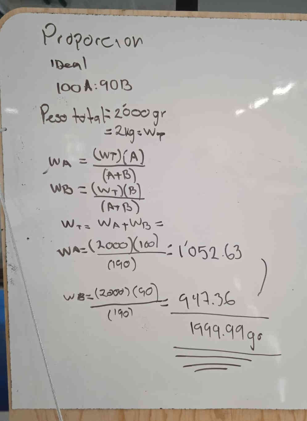 calculations
Anyways, since i had the silicon mold i just cut by hand a case to pour the resin in.
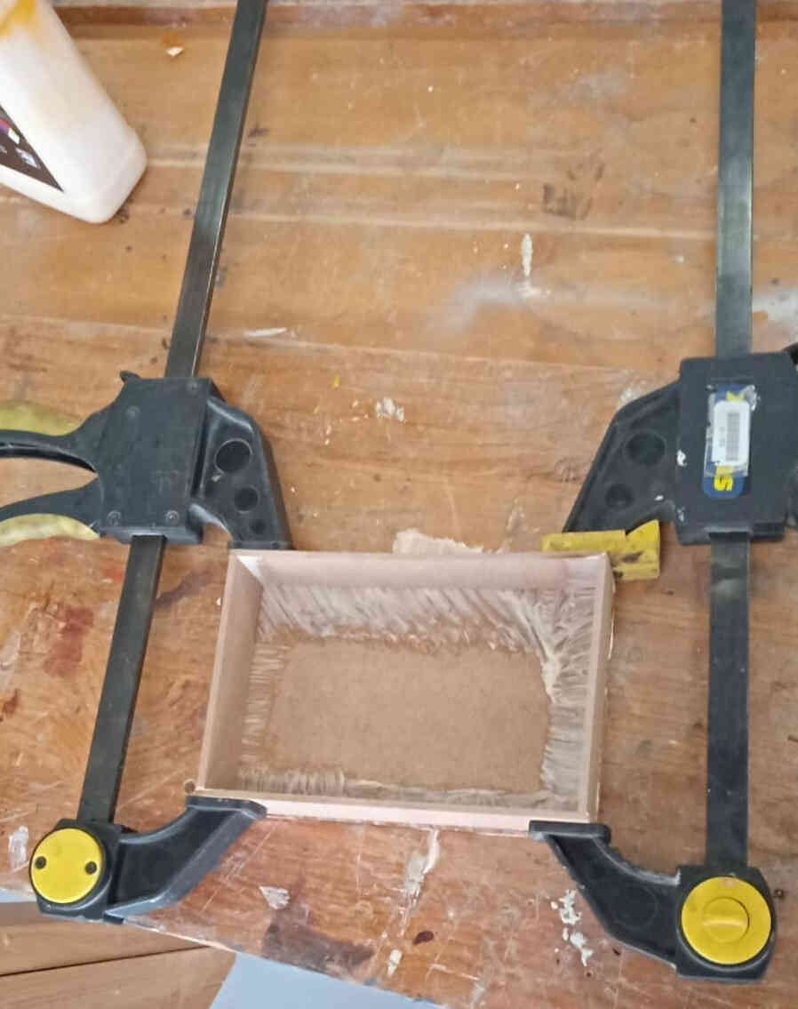 3mm MDF box clamped,glued and sealed with hot glue.
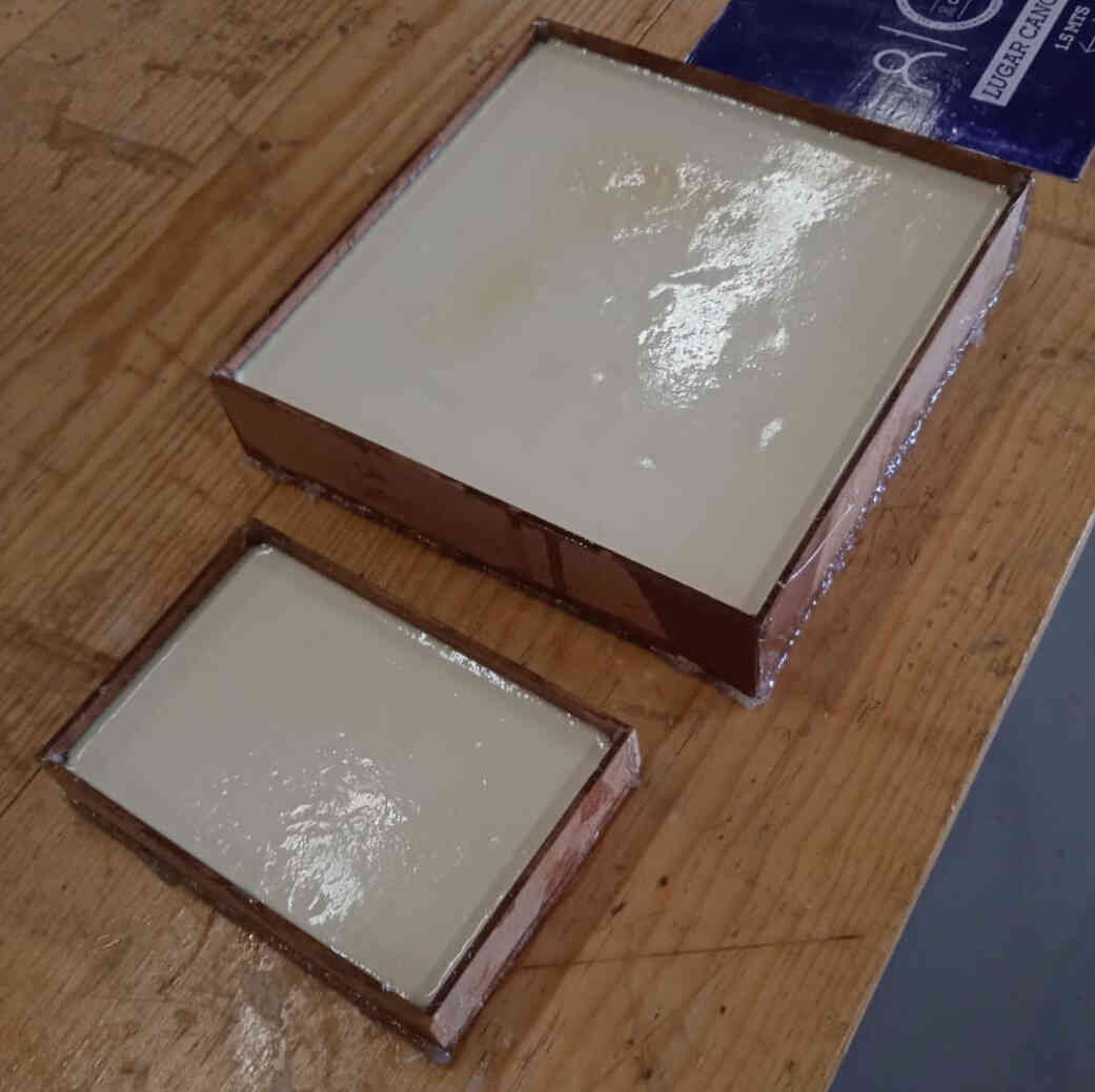 both molds (jorge javer's and mine)
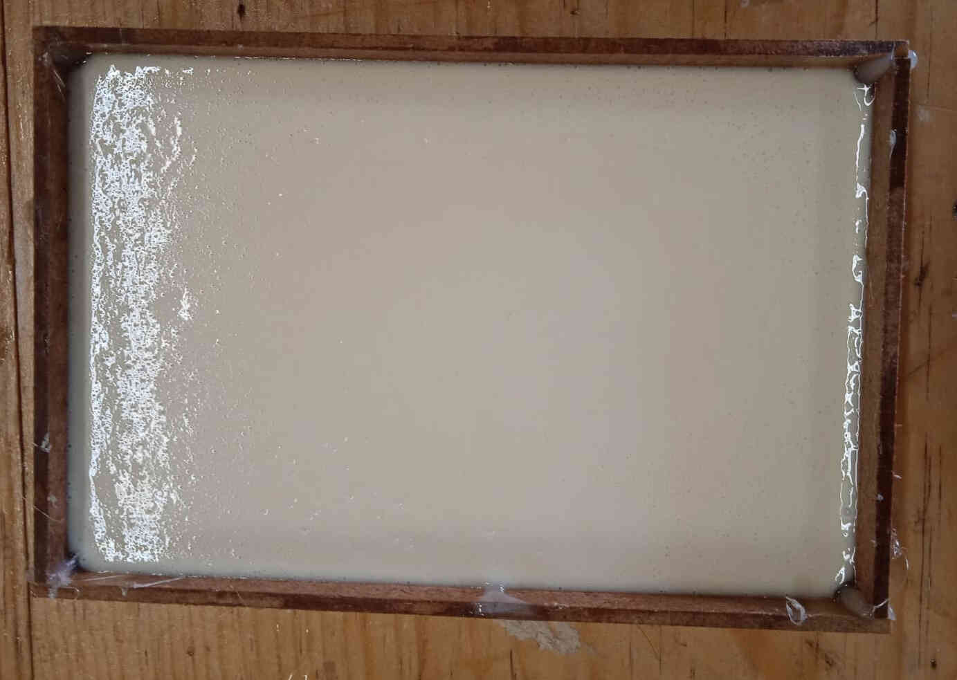 my mold
after that it was time to demold them.
But the silicon came out quite nice from the resin.
and this was the final results.
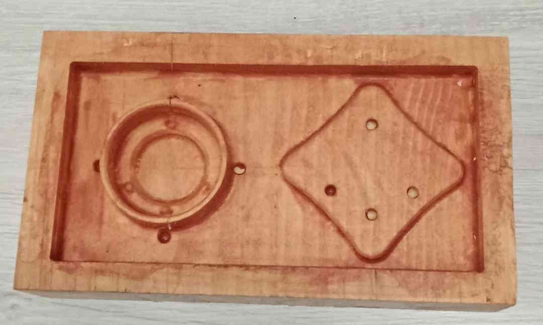 The solid pine wood negative
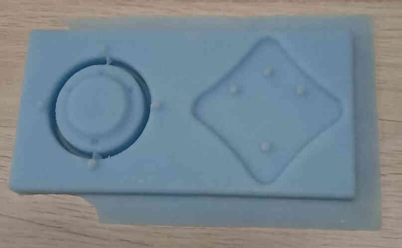 The silicon positive mold.
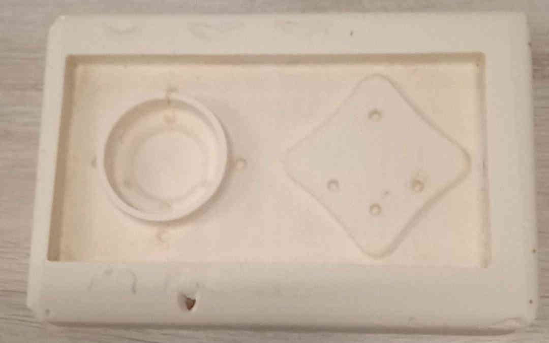 the final casted resin part.
as i said earlier. I could not use this piece in my final project due to it has many design flaws.
Conclusion
'cause i'm not used to think into the consequences of pouring material on the manufactured piece.
And how the design afect the final result.
Also learned how NOT to calculate things on the fly je,je,je.