Idea + Design
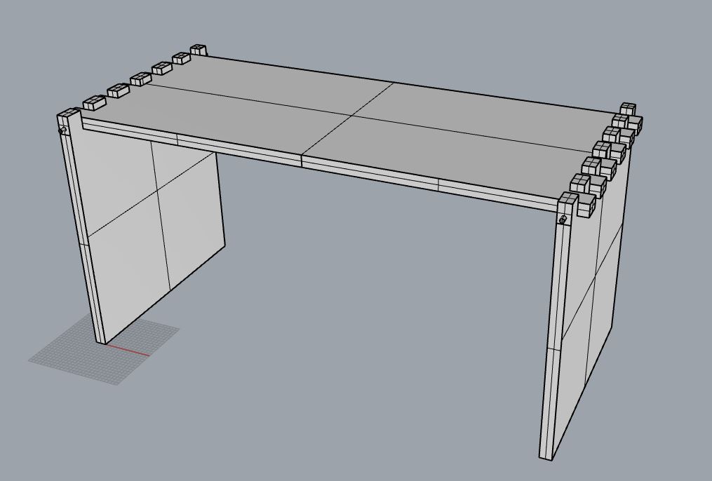
Living in my apartment in Barcelona, I only have the dining table as a surface to work on. For that reason I wanted to design a mini portable desk that I can use while sitting on my bed or the couch. I wanted the design to be fairly simple, a top and two legs. I made the top a regilar rectangle with a pocket for my many cups of tea daily, and I made two sets of legs with different lengths with holes in them. The holes could be used as shelving when the desk is not in use or they can be used as handles for carrying it around.
as simple as it can get
Preparing With RhinoCam 2020
For this part I will focus on the settings that are important to remember to select rather than taking it step-by-step as I think it is more beneficial to understand what the settings are rather than memorize the order.
Setting Up RhinoCam 2020 Machining Browser
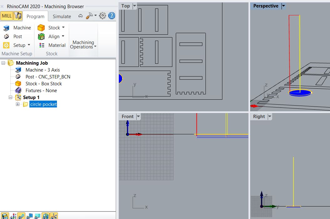
In the machining browser the first steps are to make sure you have selected the correct machine, post, and stock box.
- Machine: 3-Axis
- Post: CNC_STEP_BCN. These have presettings made by the Lab Team for the machine available
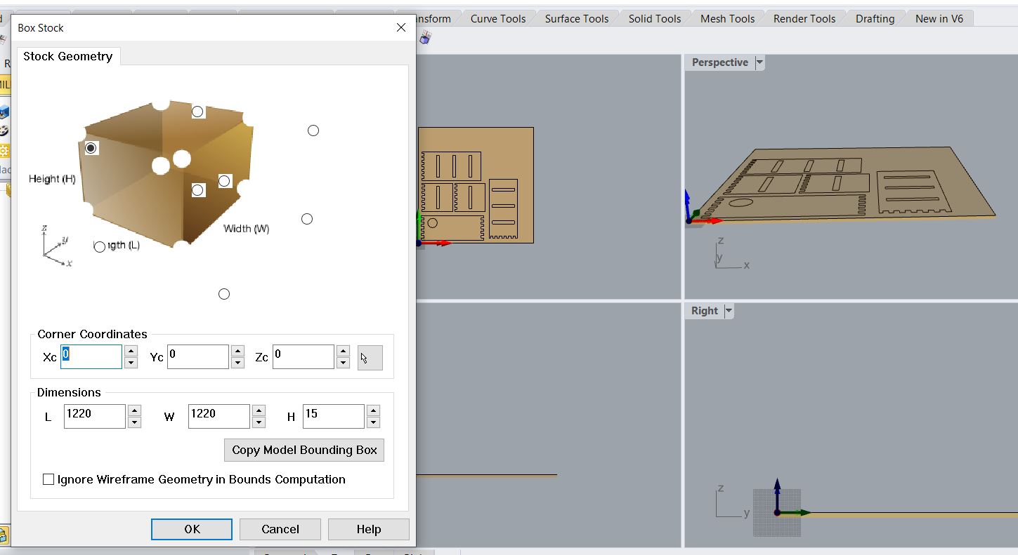
- Stock: make sure corner coordinates are at 0, which is where the machine will begin its calculations, and that the material size is the correct size, which is the bounding box.
Begin with the Jobs
Screws - Engraving
The first thing before selecting the jobs is to make sure that your cutting objects are minimum of 20mm away from the eges of the material to give space for the screws and to make sure that end mill does not accidentally cut through a screw and break. Once that is safe, we can begin with the first job which is the engraving of the middle screws. Make sure to add points in your model so that the screw is not touching your needed material or close to any profile or pocketing jobs
Mug Holder - Pocketing
The next job is the mug holder as I will only need it to make a pocket and not cut all the way through the material. In the machining operations, select 2-axis and then Pocketing. In this stage remember to add the cutting depth to the pocket depth you would like.Outline - Profiling
The last lines to cut are the outlines which we will profile. In the machining operations, select 2-axis and then Profiling
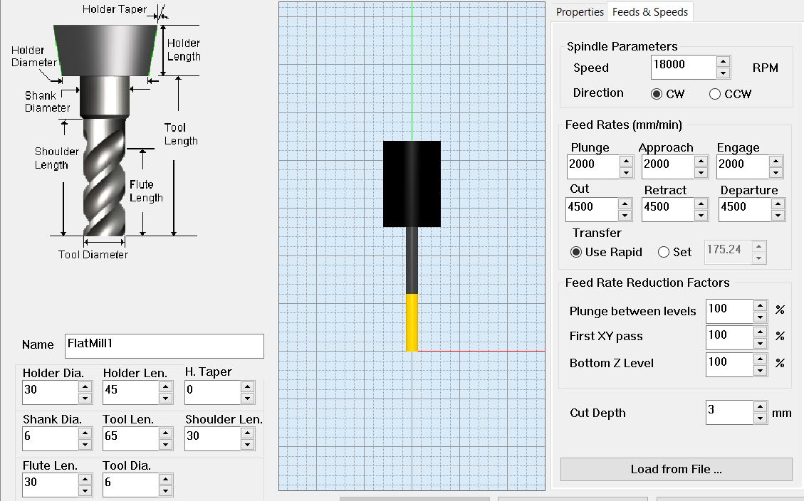
Tool Settings
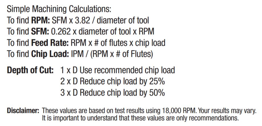
For this type of design I will be using a 6mm End Mill. Its settings are shown in the image below. Always remember to check the Feeds&Rates with every job to match the values places in this step. For more information about the CNC Feeds&Rates, you can look through the The CNC Cookbook
How do I find the correct Feeds&Speeds for my tool and material?
To do so there are a few steps to follow. The first step is to figure out what tool you need to use is, in my case I used a 6mm End Mill with a flute length of 30mm. Once you figure out the tool you can open the ToolsToday website and search in the top search bar for the name of your tool bit. Once you find it, open up the PDF Spec Sheet, the Feeds & Speeds chart. At the bottom of the chart you will see a number of formulas that will then help you calculate all the speeds needed. When calculating, a good rule to remember is that the bigger the chip is the faster the IPM is.
Important Settings To Triple-Check
Cutting Direction
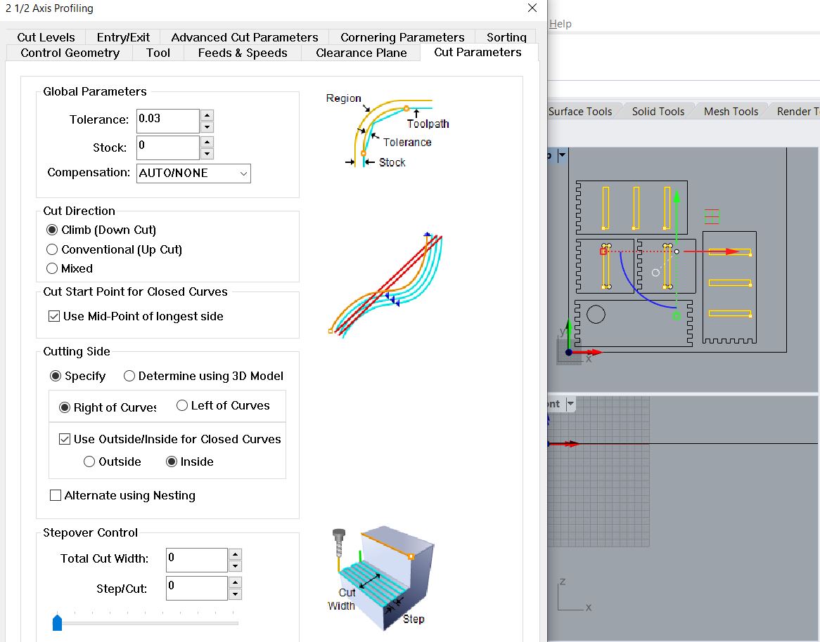
In most designs, there will be a need to cut on the inside of the line or the outside. Always remember to double-check what the design needs and then make sure that the correct option is selected. The difference between where it is cutting is directly related to the dimensions of your pieces. Onc the end mill goes through the material the part that is left on the same side will lose material as it is the one being cut out of and the other size will be the dimension you needed. While cutting pockets or holes inside a larger design, inside cuts will almost always be used. If you are cutting the larger object, you will want to cut from the remaining material.
To get to the cutting direction setting and select inside follow these steps, Cut Parameters > Cutting Side > Use Outside/Inside for Closed Crv > Inside
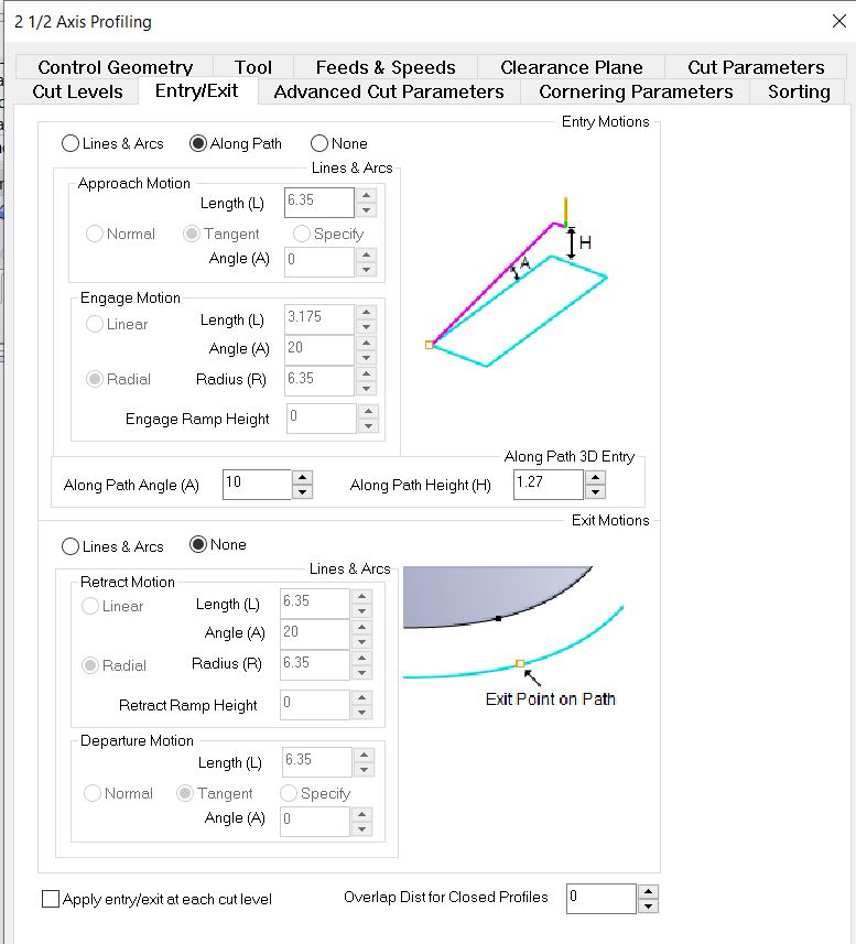
Entry/Exit Direction
When you are profling, there are different ways that the machine will approach the cut. Meaning from home, the machine will move the end mill either directly into the material perpendicularly or make a slope into the material. To decrease the load and tension on the end mill a good setting to use is the sloping. In sloping there are also two ways that it can approach the starting point, either along the curves actual path, or while it is in motion towards the curve. To avoid any random cuts in our material, it is best to use the option that is along the actual curve. To get to this setting you need to go into, Entry/Exit > Along Path . Now you have the approach to your cut safely set up. As for the exit, there is less tension or load for when the end mill is leaving the material, especially that I am using an up-cut, and for that reason will allow it to directly leave the material perpendicularly.
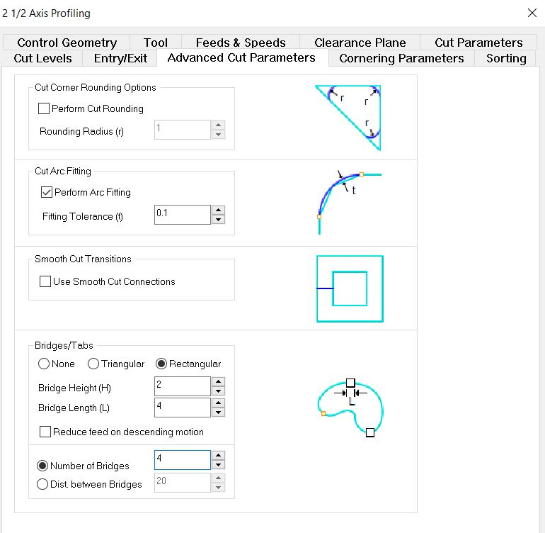
DogBones
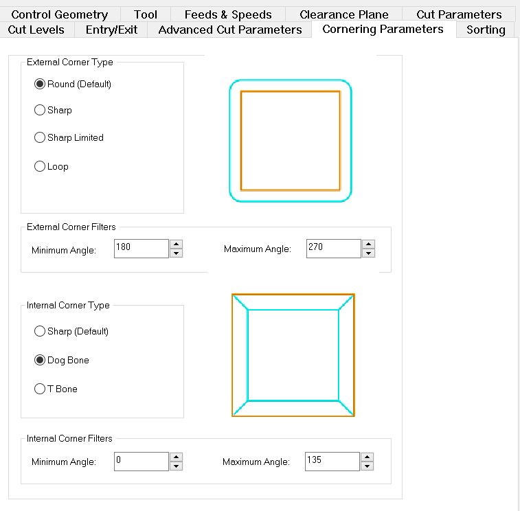
In the cutting process, you may find that some inside corners that you have in your design are simulating or cutting as semi-circles rather than with corners, which happens because of the nature of the circular milling bits. The solution for such a problem is using DogBones or T-Bones. To learn more about inside corner, why they happen, and dog bones visit The Inventables Workshop's Blog Dogbones are more commonly used and, in short, they are a way to allow for the designed corner to exist without having exactly physical lines meeting, they round the corners and pull them out midway. In this version of RhinoCam 2020, there is an automatic selection of the DogBones. To reach that setting go to, Cornering Parameters > Internal Corner Type > Dog Bone
Tabs
Once the cutting has reached its last few layers and because of the speed and torque, there is a tendency for the object being cut to fly or lift with the end mill. For that reason, there needs to be a safety measure. One measure is to leave rectngular or triangular tabs in a few locations of the piece or to keep an onion skin layer at the bottom of the piece. Tabs can be easily cut and sanded after the piece is done and onion skin can be easily cut by hand. For this design, we will be using tabs. To reach the tab menu go to, Advanced Cut Parameters > Bridges/Tabs > Rectangular For extra safety measures make sure to have 4 tabs under Number of Bridges.
Weird
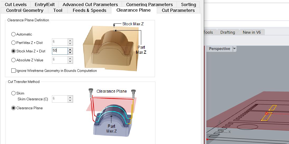
While I was simulating the file to check that all the cut lines are okay I noticed that the machine is going up to a larger height while traveling towards the cut. The problem with this is that it will increase the cut time.
After some investigation I found that the settings for the Clearance Plane was too high and I needed to adjust that. Toadjust the clearance plane settings, go to Clearance Plane > Clearance Plane Definition > and I used the Stock Max + Distance of 50
Simulating
After every job generated it is always good practice to simulate to make sure that it is cutting through, and cutting the correct lines. You can right click on a job > simulate
Final Project
Computer Controlled Machining held a very important role in my final project as the body is fully manufactured using the CNC. In this project I used 2.5D for the table-top (in wood) and 3D milling for the base (in foam).
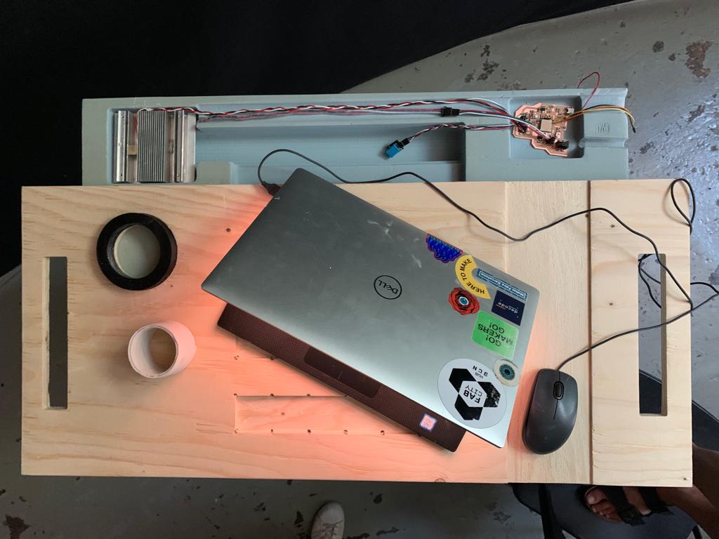
Table Top | 2.5D Milling
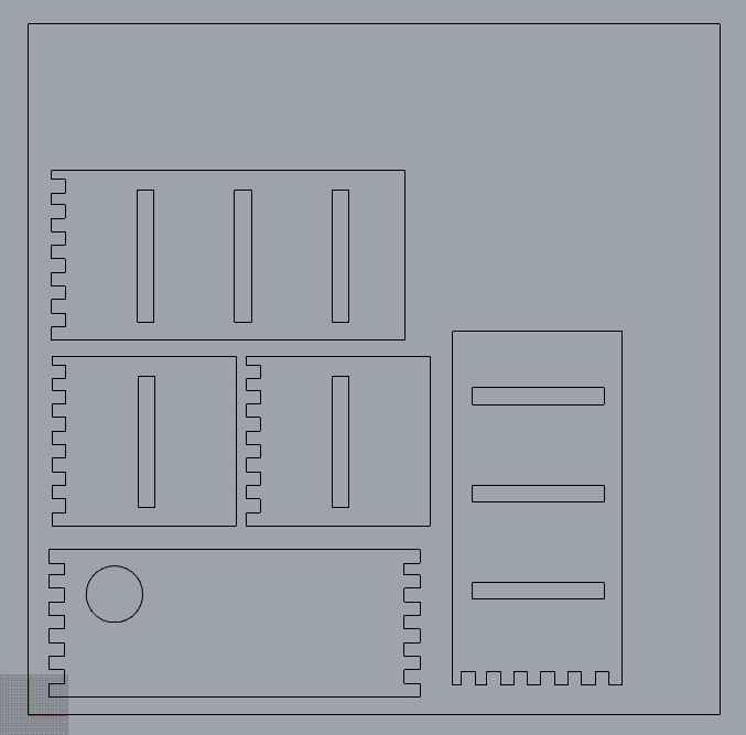
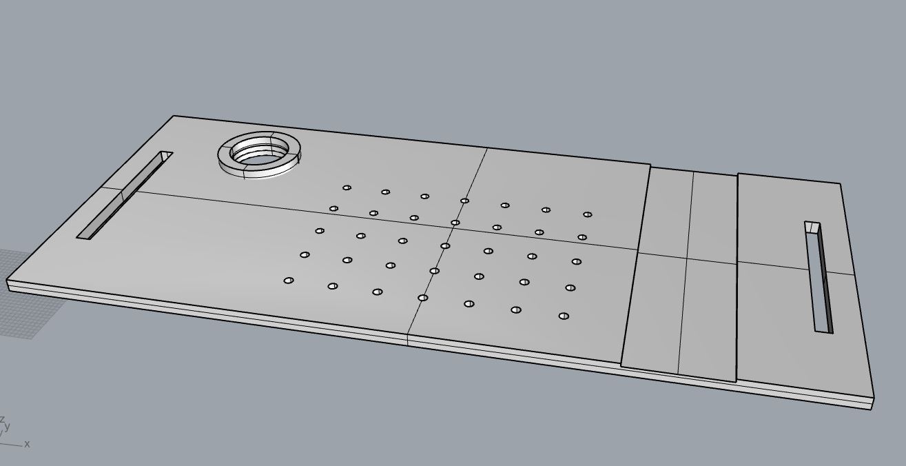
The table top was made out of 15mm Plywood and included holes, pockets, and profiling, each of them for a certain function. Looking at the picture above we see the rectangular profiles on each end of the top which are used as handles to carry and transport the top around. The circular hole on the left of the laptop is used to fit a warm drink inside and to keep it warm. The pockets and holes directly under the laptop are used to allow the cool air to enter and keep the laptop cool. Finally, the pocket on the right of the laptop is used as a mousepad.
Once the Rhino model was complete to my liking as shown above, I used the RhinoCam plugin to create the drilling, profiling, and pocketing jobs. Ussing the steps outlined above in the "Preparing With RhinoCam 2020" section, I set up the design to be milled.
Once the code files are saved on the USB drive it is time to move on to setting up the CNC with the material and making sure the 0,0,0 access are correct according to your material. The first step is to turn on the machine using the big on switch. Some CNCs (like the Shopbot) need to have a warmup routine completed before using it but the one we used at the lab did not need a warmup. Since we did not need to warm up the spindle, we loaded the 15mm scrap sheet on to the bed. Once it is loaded, we went back to the machining program and set up the xy 0 by moving the bit to the point we wanted and then clicking on "set zero". For the z-axis, you will need to use whichever accessory your machine comes with that can tell the z-axis. In our case it was a button like cylinder that is placed right underneath the bit, the machine will continue moving downwards until the tip of the bit touches the metallic cylinder, repeats it two more times, and then goes to a safe z-height.
Now that the 0,0,0 are set it is time to run the first post file which is the screw location. The benefits of making a drill point as the screw instead of eyeballing it is the safety of the machine and bit. By making drill points on the material, you make sure that the next jobs will not be interefered with by the screws. Once the screws were set into the material it was time to run the next files which ar the pockets and then the profiles.
Luckily, until this point we did not run into any errors.
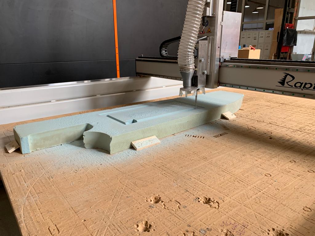
Table Base | 3D Roughing & Finishing
In the foam base, I have used 2-sided milling. On the top edge there are grooves for the integration of the electrical pieces and the airflow. On the bottom/back edge there is a 3D roughing and milling to give curves so that it is much easier to rest on all surfaces.
The first side to be milled is the top section. The steps of setting up the machines for this case are the exact same as the previous. The only difference will be seen once the material is flipped over for the milling of the back side.
As seen in the videos, there are two holes made (that will later be used for alignment) and there are wooden pieces screwed on the bed around the piece. The wooden pieces are used to fix the material onto the bed, another technicque would be to use double-sided tape, in the case of this high-density foam, it is best not to screw it directly onto the bed because of its density. Make sure to have the wooden pieces on all sides of the material so that no matter where the force is coming from it will be held in place.
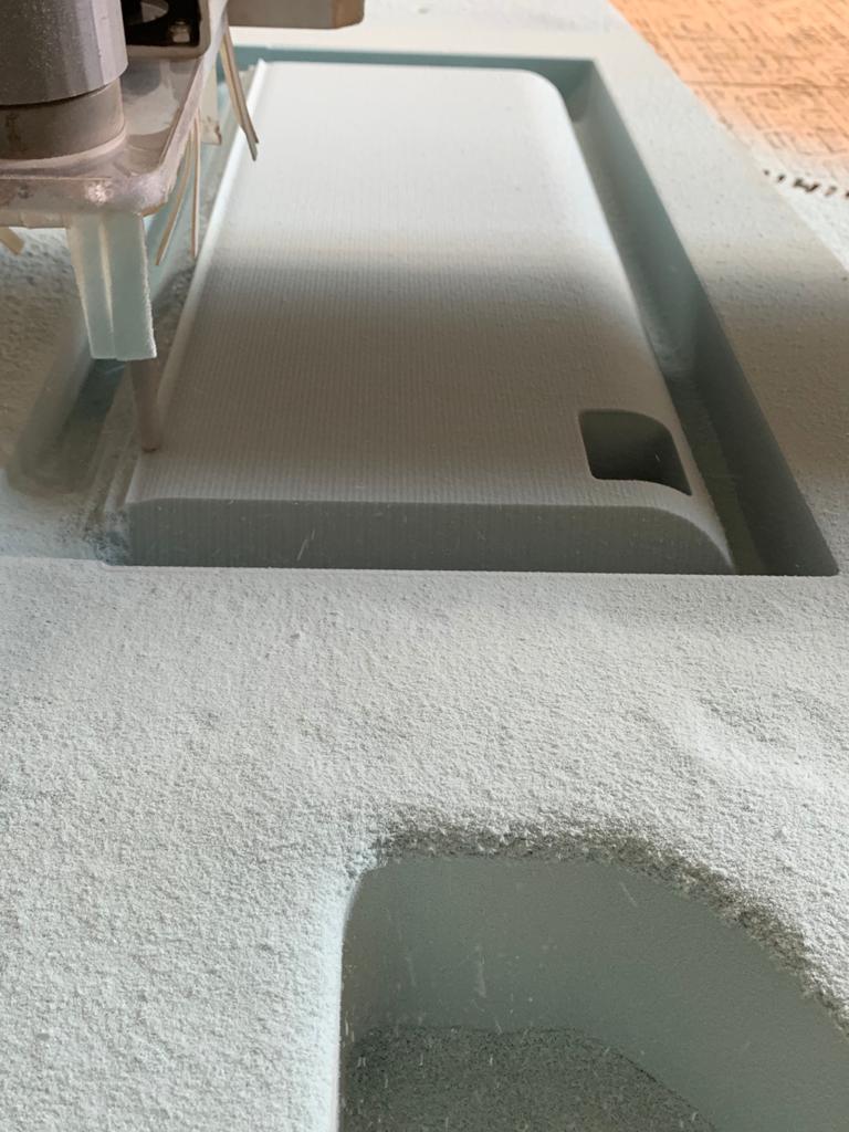
Once the top side is complete, it is time to flip the material over. To do so, first move the machine to a safe xyz position so you do not hit it. Next remove all the key wooden blocks around the material so you are able to remove the material and then flip it in the same direction you had previously flipped it on Rhino. (In my case it was flipping along the long edge). Now that the material is flipped it is time to use those alignment holes. Use two long rods and place them in the holes and then find the indentation that is made in the bed of the CNC that aligns with the drilling hole made on the first round earlier. Once the rods fit perfectly in those holes we know that the piece is completely aligned and will mill correctly. Now it is time to send the roughing and finishing files.
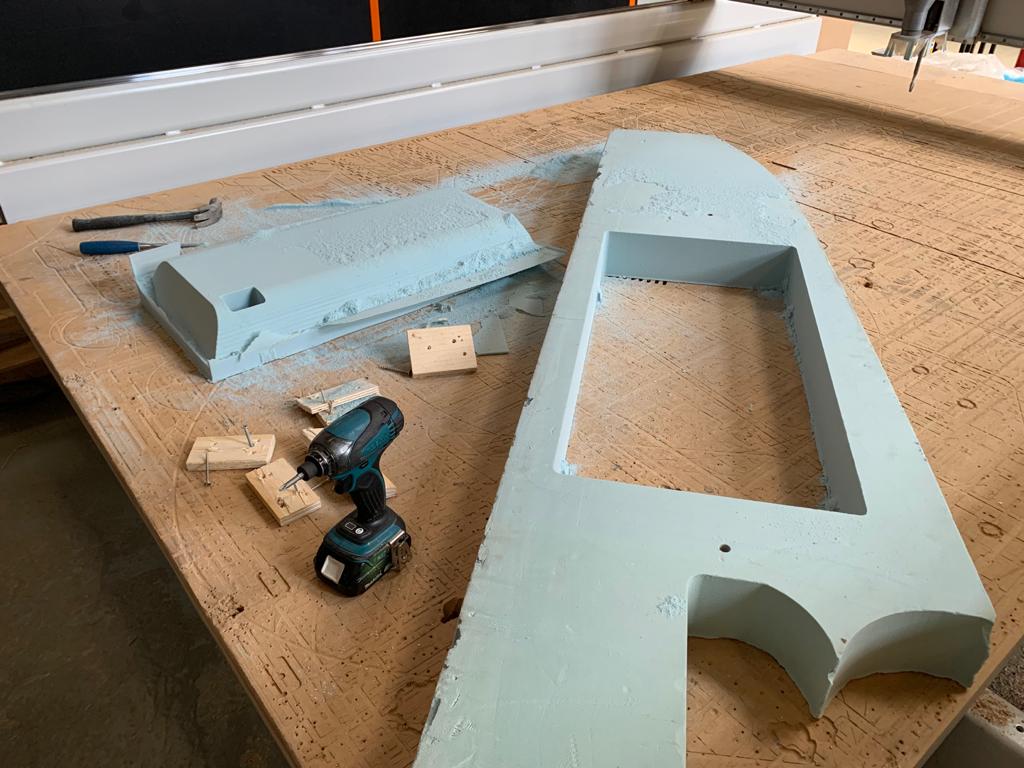
Once the jobs are all done, you can use a chisel to take the piece out. However, because the foam can very easily break with a chisel I opted to remove the outer scrap material first and then moving the piece. Once the piece is out it is time to sand it. I used a 120 grit sandpaper and then went to 1000 for smoothness.

Final Thoughts
One point that many forget to consider, which I forgot to as well, is the tolerance needed between different obects to fit perfectly. As I made two different lengths for the legs of the desk that I would like to change between I did not want it to be a press fit. Instead, I would like to keep distances between the grooves and have aligned holes where I can use a dowel to lock them. This method will also allow me to change the angle that the legs are standing on.
Files