Group Assignment
The group assignment was worked on by the full group. (We have 2 SRM-20 machines that were available for use by a large number of people.) The results of the test is outlined intensively by
David Prieto González and
Minh Tue Ngo
Machine Settings
Some important machine properties we found on
Roland MonoFab SRM-20:
- Work area: 203.2 x 152.4 x 60.5mm
- Loadable workpiece weight: 2kg
- Operating speed: 6mm/min - 1,800mm/min
- Spindle speed: 3,000 – 7,000rpm
- Input Format : RML-1
- Material: Modeling Wax, Chemical Wood, Foam, Acrylic, PCB
In the machine settings, the speed was changed according to what worked best with the milling bits and the machine, which was
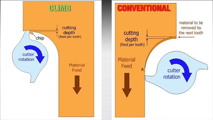
3 mm/s. The x,y,z origins were at 0; the x,y home was 0 and the z was 7, to keep a safe distance from the FR1, to maintain the bits, while moving to home. In the mill raster 2D option, I selected the direction to be at climb rather than conventional.
As mentioned during classes, generally climb milling is better because it has a cleaner surface finish. However, it has a subtle problem because it is trying to lift up traces that conventional machining might not.
Some points learnt and to keep in mind are that although it will take a lot of time, it is best to keep the speed low at around 50%, we saw that it cuts much better and is better safety wise. Another point is that you should always double-check the distances between the traces before even exporting because it is definitely a mess when you need to start over with the traces.
PCB Board Manufacturing
To begin creating my own PCB board, I decided to follow a tutorial I found on the assignment page. Building the FabTinyISP. The decisions to follow this tutorial was because it was thorough in the explanation and well documented. Reading through the first part of the paper, it explained the fabrication of the board. As the board milling machine is technically a nano cnc machine, I understood the basics of how to use the machine. A point that was interesting to keep in mind was the traces, width between the traces, and the layers of the board. The board that I have chosen to work on was, ISP, a 1 layer board and was not too complex with the width between the traces; according to the group test beforehand we knew the trace width to use safely.
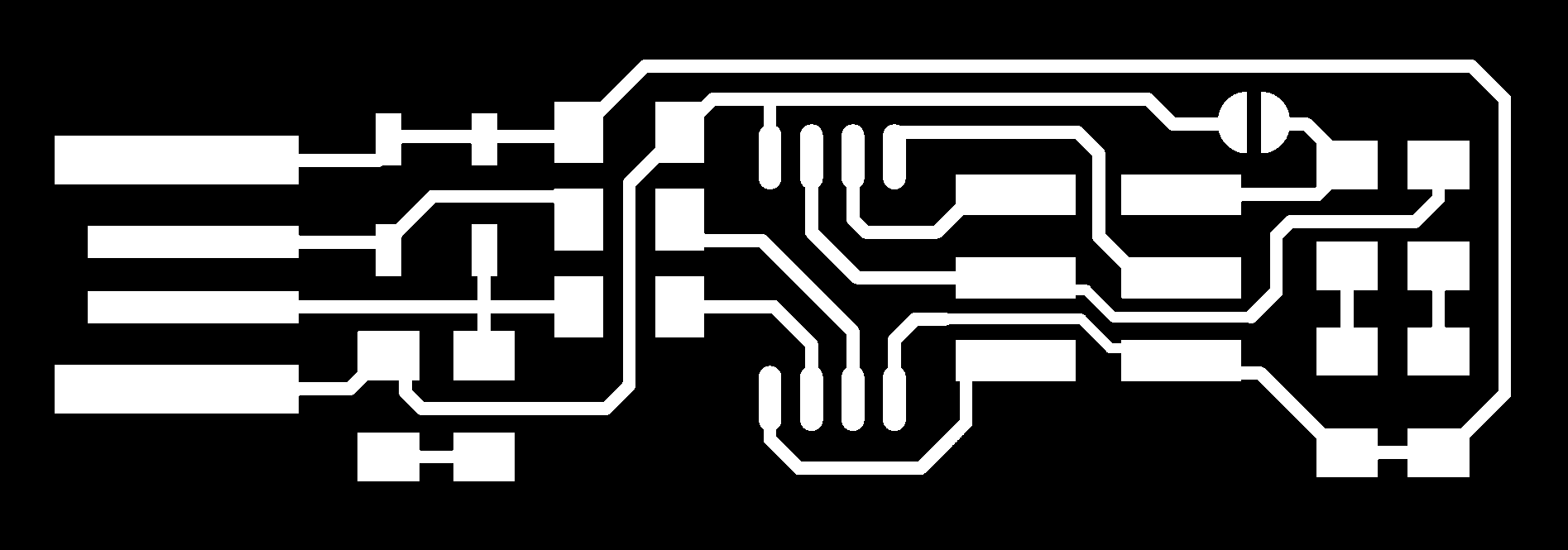
As I did not use mods in the computer-controlled cutting week, it was interesting to use it for the milling of the boards. I donwloaded the traces and the outline of the ISP boards and opened Mods. In mods I uploaded the image, png, of the traces first, checked its overall size, selected the correct machine which is the SRM-20.
Two of my classmates and I decided to use the same PCB so as to save material and to take advantage of the time.
- We fixed our files to be located properly on the material by changing the x,y for each file, keeping in mind the size of each board and some extras around them.
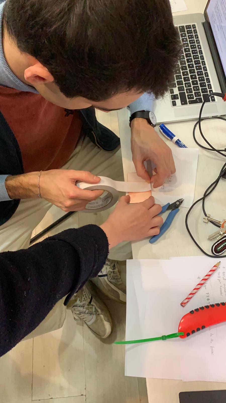
- We then used a brush to remove and dust left on the base to level it out.
- We placed double-sided tape at the back-side of the material and stuck it to the base of the machine to make sure it stays firmly in place.
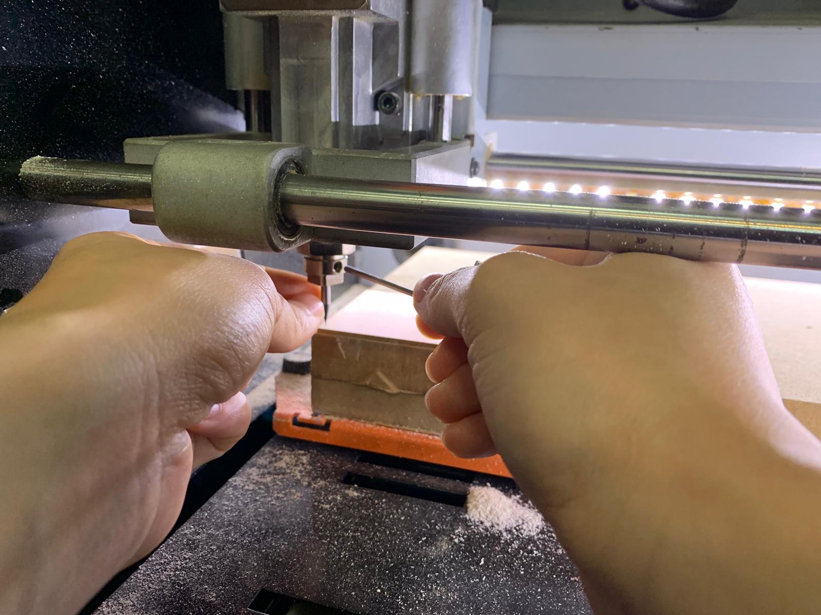
- After that, we set the x,y by moving the head as close as possible to the corner.
- For the z we used a different method which was to bring the head down quite close to the base and then loosen the milling bit and then allowing it to softly touch the base and retightening the callout.
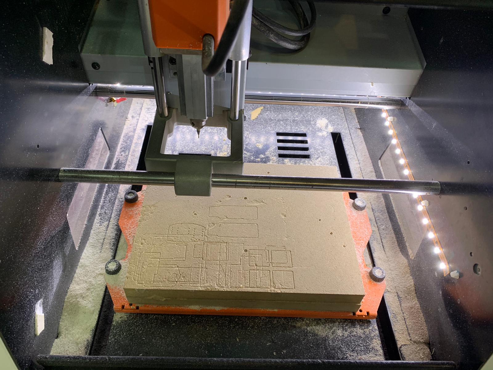
We used two different tools. For traces we used the 1/64 as we needed the width between traces to be smaller and for the outlines we used the 1/32 so as it does not break as easily. - Once the 3-axis were set, it was time to add the cuts to begin the jobs. Once the jobs began we made sure that the milling bit was stable.
- The settings that we decided to use were: traces speed was 3 mm/s and for the outline was 0.5 mm/s.
Components
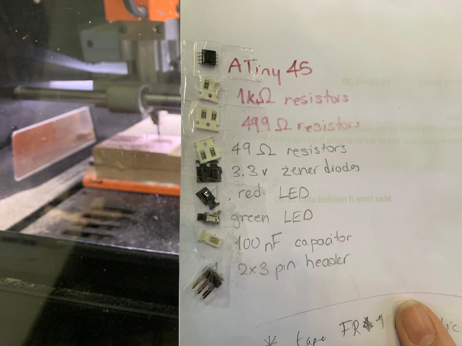
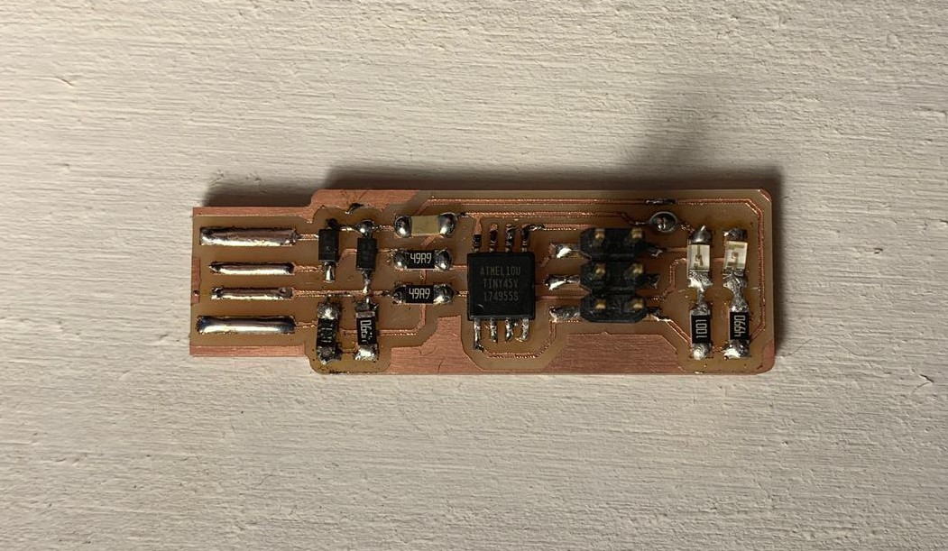
While the boards were cutting, I began collecting the componenets needed to later on solder and test them. This type of board contains an ATiny45 microcontroller, 6 different resistors with 3 different Ohms, a zener diode, LEDs for signaling communication and power, a capacitor, and a pin header.
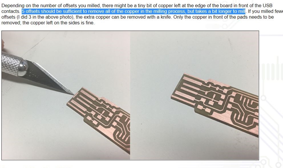
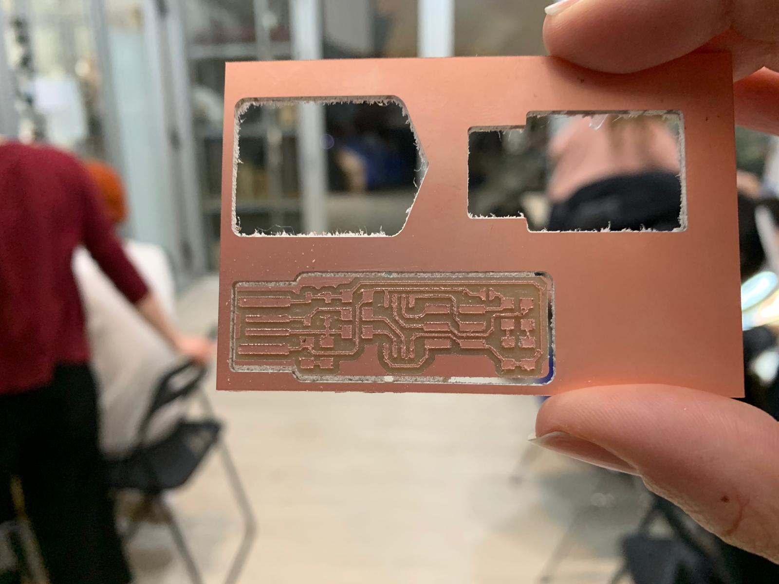
The cutting was done, and since I had used climb milling some edges of the cuts came out a little dirty/dusty and looked like they were a little lifted off of the board. I used a sponge-like thick material to clean it to begin soldering the components on the board.
Soldering
Using the link mentioned earlier I was able to follow the diagram for the placement of the components. In the link and in class, the first tip that was provided for soldering was to solder the hardest parts first, the ones that would be too difficult to reach later on. The most difficult component was the microcontroller as it was in the center and had 6 small legs. I soldered one of the legs first to hold it down, and make it easier to continue soldering the rest of the legs, by placing the solder on the iron until it has a good amount on it and then placing the iron on the the first leg and moving it in a brush motion downwards toward the board.
My first mistake of soldering was not remembering to check if the component had a direction and if it was aligned with the board. Lucky for me for this component it was aligned correctly.
The next components I soldered were the two resistors and capacitor on the left of the microcontroller as I wanted to leave the pin header to the end. The pin header is a larger component and would make it difficult to solder. Later I moved to the left again, where I began soldering the resistors.
This is where I ran into the second mistake because I did not realize that the resistors were of different resistances and misplaced them.
I removed the excess solder by using the copper braids; where you place the copper braid on the excess material and place the iron on top of the copper braid. That way, the solder sticks to the copper braid and off the board. Once done with everything on the left of the microcontroller I moved on to soldering the far right, the LEDs and their resistors. This was the trickiest part in my experience because the space between the LED and the resistor was narrow and the soldering iron kept leaving the two connected with solder.
After they were soldered and so was the pin head, I realized that some components had white solder points rather than the clean shiny look they should have. I went back with the iron and heated the existing blob for a few seconds and then added a little bit more solder and it became much cleaner. To finish off, I placed a point of solder to create a bridge to the multicontroller for the programming part and once it is programmed that soldering point will be cut.
Some Tips I Learnt
- If the solder point is not a circle and has a little bit of a sharp point, that means your soldering iron might not be hot enough
- If the solder point follows the soldering iron once you move it, then your iron might not be hot enough, or you might have moved it a little too early away from the component
- If the solder point is not shiny, you can reheat it and add a little amount of solder to clean it up
Software Installation
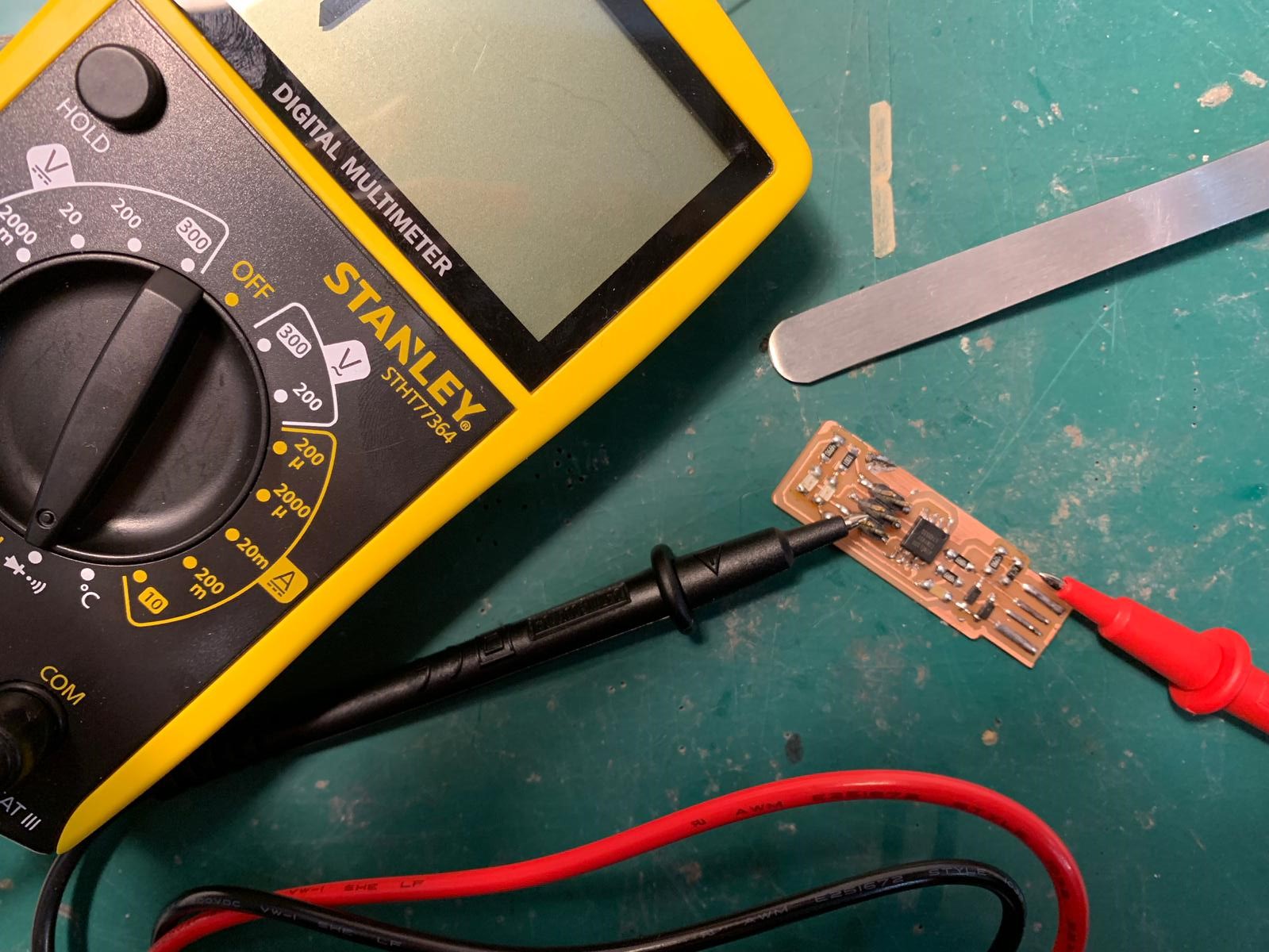
After the soldering was complete, it was time to test whether the connections were continuous. I used a multimeter and followed the connections showed on the image of the board. All the connections, thankfully, were successful.
The next step is to install the softwares that can speak to the board. From the link, tutorial, I have been following there was a link to another tutorial that shows all the necessary softwares/drivers to install. Using the GNU AVR toolchain on Windows 10. The first step from the tutorial states that downloading everything necessary for Windows is challenging; and challenging it was.
I followed the given steps to install Atmel GNU Toolchain through the Atmel site, download GNU Make and launch the installer, and then download avrdude. In the tutorial it mentioned that these steps are the easier method for Windows 10, I, however, have found that they did not work for me. When all the steps were taken and tested on Git Bash I found that they do not respond well or at all. For that reason I decided to follow a different set of steps.
The set of steps followed
1.
Install WinAVR 20100110 through their website and launch it.2.
Open the folder and find the folder bin. Inside bin delete two files: avrdude.conf and avrdude.
I personally have the older places in the C:\\ folder3.
Replace the deleted folders with the newer version of them. Version 6.3 2016. *will be provided here*4.
In control panel > systems > advanced system settings > environmental variables > path > edit > new > browse > find the file location and add the bin folder 5.
Connect the AVR MKII programmer to your computer and to the board 6.
Install Zadig and launch it 7.
Once launched and the programmer is > select "libsub-win32 (v1.2.6.0)" > replace driver 8.
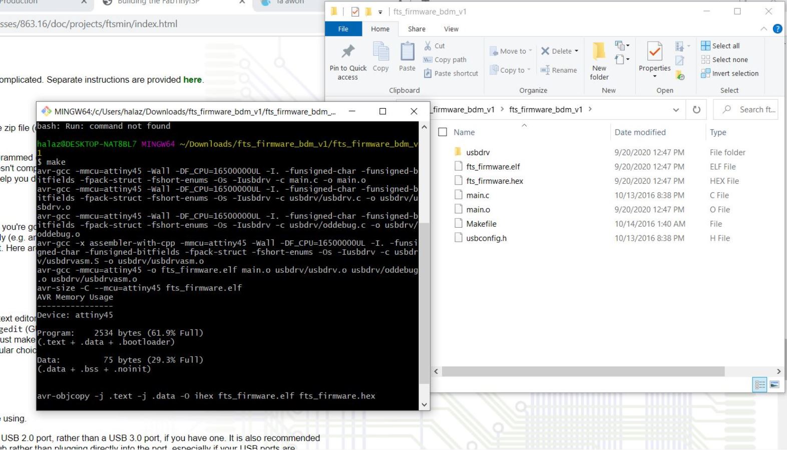
Download the firmware source code from the tutorial mentioned earlier *link will be uploaded soon* 9.
Open Git Bash > navigate to folder "cd <>" 10.
Type "make -v" > click enter > you should see the version of the software
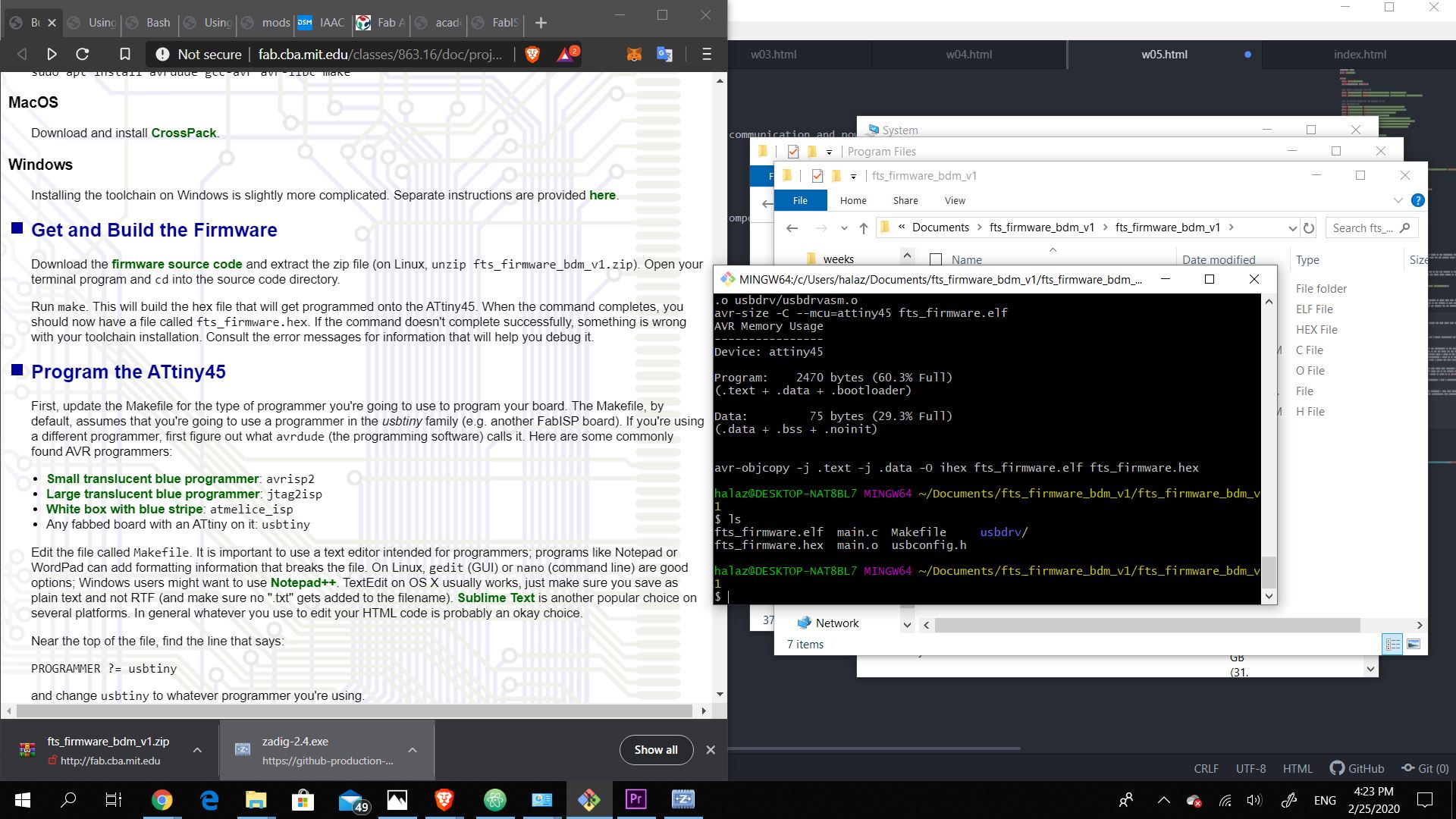
11.
Type "make flash" 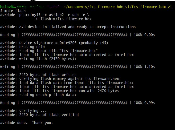
Programming
After installing all the correct softwares, I plugged the board into the USB extension and the AVR MKII programmer. The good news was that the correct lights were on, the board had the red LED, the programmer had the green LED. The bad news was that the computer was not reading the board.
Final Thoughts
Producing a PCB board is not as difficult as I have expected. Just always remember to double check your milling bits to be placed correctly and your z height to be greater than 0 for the jogging. I was expecting soldering to be a frustrating experience but it turned out to be a little calming!
Files