Final Project Diary and Concept Update
6th of June, 2020
Today I decided to change my final project again!
I needed to have irrigation working on the farm, and I did not need more chickens right now, so, well, I changed again. It doesn't mean I gave up on the chicken egg incubator. It only means I might have TWO final projects :-). Well, maybe not, the reality is that I will focus on the irrigation: my fruit trees need the water, the greenhouse too. I need it so much right now, and I need it to work well, that it really makes the change worth it.
So no Chickens! YES WATER! Maybe also Chickens.
Design of my new proposal
As I am writing this, there are no design files at the moment; there is a sketch of the code and there is a prototype on a breadboard!
On the other hand, there are requirements for the hardware and for the software:
Software Requirements and stage
- Simplify the code by creating more functions;
- Try to separate the HTML part for cleaner code;
- Improve the appearance/interface of the code;
- Add readings to the HTML;
- Add a log of occurrences like overcurrent;
- Add more safety for the equipment;
- Add a phone interface (APP);
- Add a function to set the current time;
- Add a renaming function to each relay, so one can relate the relay to the area of interest, or at least rename the relays to actual areas of the farm.
Design Requirements and situation
- Needs to be at least water resistant;
7th of June, 2020
As of today, 7th of June 2020, the development is like this.
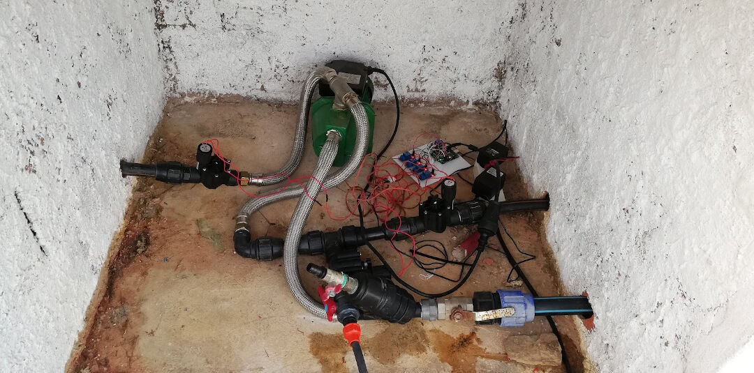
The code running on this setup can be found on the Fabfarm GitHub: Autovalve.
Shakeel, one of our volunteers, managed to create a version that runs on an ESP8266, which can be found in the same repo here. Due to the pandemic situation he left us in a hurry and did not have time to test his code, so it worked but was not stable, because he heroically attempted to share the analog pin with the Wi-Fi, leading to Wi-Fi drops that made using the system almost impossible. This is the code that I started with.
8th of June, 2020
After many hours trying to understand the code, I managed to port Shakeel's code to an ESP32 and also split the file, with each function in a separate file.
In this video I show the progress I have made so far in merging the codes and getting them to work on the ESP32.
Porting the code to the ESP32 might be simple for a programmer, but it took me many hours.
Steps:
- Separated everything that was already a function into its own file to make it more readable;
- Then opened another session of the Arduino IDE and started copying every part of the code, line by line, to the new session; in this session I renamed the main file to "esp32irrigation"
- Remapped the pins to ESP32 pins
- Ran Beautify on the HTML in Brackets
- Organized the code so the pins are at the top
- Created variables for the RTC pins
- Commented out the parts of the code that print errors to the serial monitor
The code is too big to display in the HTML, so I will leave a link to the state of the code as of this early morning: code here.
Here in this video you can see the testing setup of the current irrigation system of the farm.
9th of June, 2020
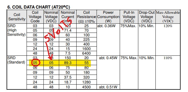
Today, after testing the relays, I realized that some relays work and some don't. After testing on the lab power supply, with 5 volts applied directly to the signal pin, I believe this is due to the low voltage being supplied by the ESP32, or the signal voltage.
I then watched GreatScott!'s video on YouTube about relays and optocouplers.
I will make sure the relays have at least a 5 volt power supply, which is their required voltage according to the datasheet. The signal should be fine at 3.3 V. It will be tested in situ.
The other point is the current reading, which is completely wrong. In order to have the irrigation system working, I will have to run it without current sensing until it is debugged.
10th of June, 2020
After the tests, the conclusion about the voltage problem is that the ESP32 should not supply power to the relay; that should come from an external power source, set at 5 volts. The signal can come from the ESP32 unchanged, but the ESP32 must share the same ground.
More changes in the code:
- Increased the interval at which the time is displayed from 3000 to 5000 ms (5 s) in the variable
RTCtimeInterval - Increased the interval at which the setup is displayed from 10000 to 30000 ms (30 s) in the variable
configTimeInterval - Gave recognizable names to the relays in the HTML interface
- Cleaned up the serial monitor a bit more by removing the seconds from the settings display
I will put the setup back to work this morning, set times for each irrigation and field test the ESP32 irrigation module.
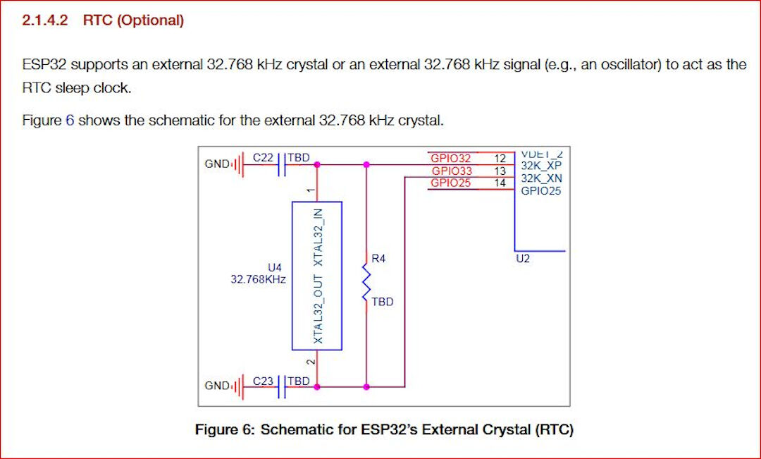
Strangely, the external RTC clock is not keeping accurate time. I will look into using the internal clock with an external battery in case of power failure.
According to this closed issue discussion in the ESP32 repo on GitHub and this ESP accuracy topic, the internal clock will drift ("Internal RTC clock frequency error is about 5%"); this can be solved with an external 32.768 kHz crystal, assembled according to the schematic below:
Another solution would be to have the ESP always connected to the Internet, grabbing the time from the Internet to compensate for the inaccuracy.
After wake-up update
Today I went on to install the temporary testing setup. I troubleshot a few problems.
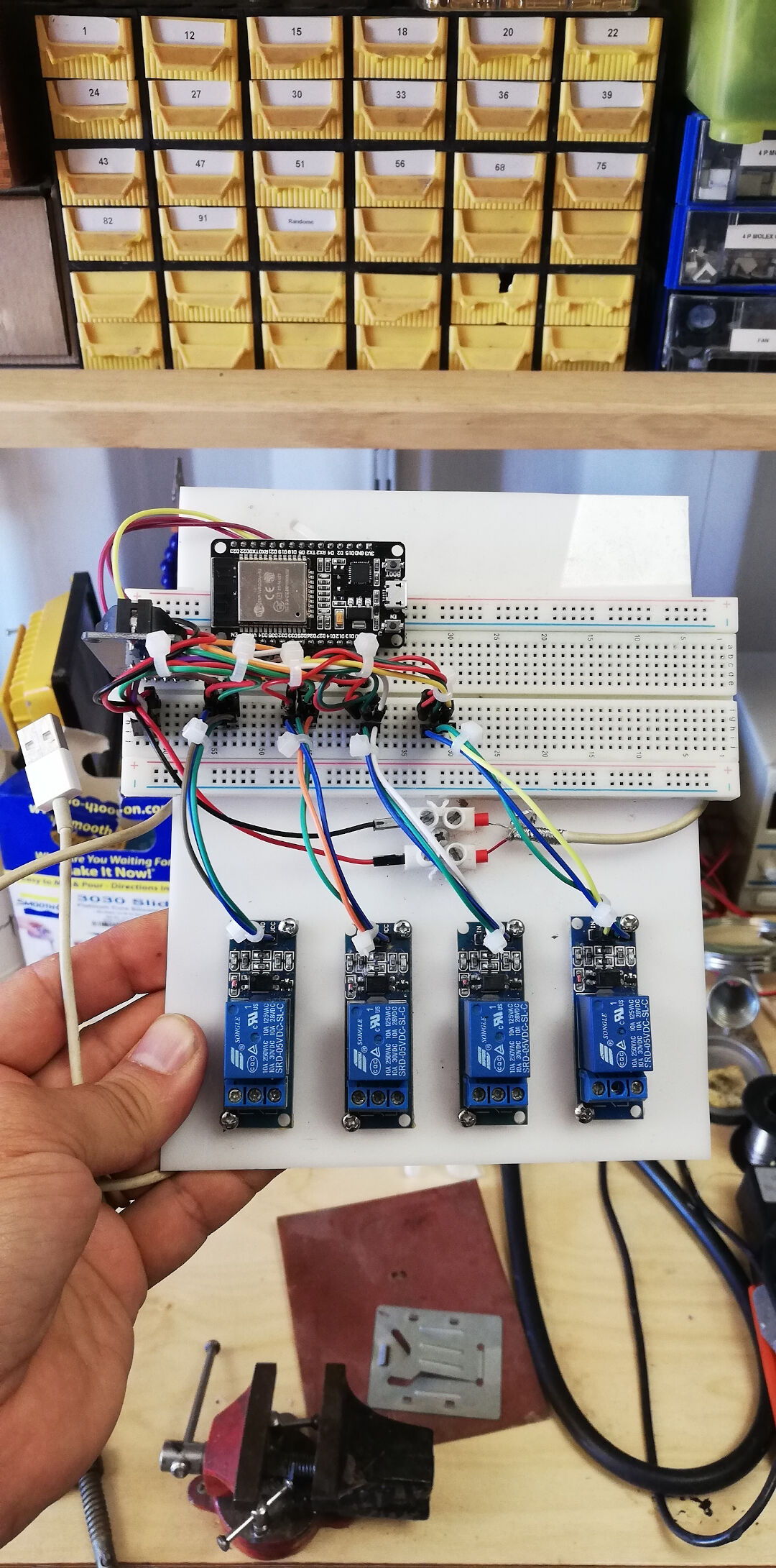
- The setup was not working when disconnected from the computer. Solution: the power wiring was not correct; I ended up connecting 2 USB cables, one for the ESP32 and another for the relays, and they both share the same ground. I might have solved the RTC clock problem with the same approach as well.
This is how the prototype looks now:
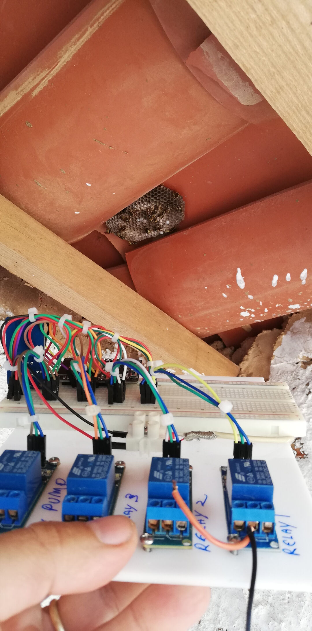
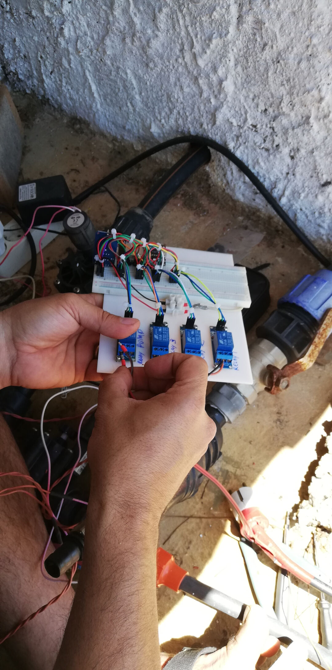
After the tests I went back to the code for more customization.
I first watched a series of videos on YouTube about how functions really work, and then started creating even more functions.
Basically, I looked into how to reduce code repetition and how to send a value to a function.
From the code available I created this function:
void turnOffRelay(int valveHere){
  // wait then turn valve relay OFF
  Serial.print("Waiting ");
  Serial.print(waitTimeValveOff / 1000);
  Serial.println("s before deactivating Valve Relay 3.");
  delay(waitTimeValveOff);
  digitalWrite(valveHere, LOW);
  valveHere = 0;
  Serial.print("*** Valve Relay ");
  Serial.print(valveHere);
  Serial.println("3 turned OFF ***");
}
Warning: valveHere = 0; runs before Serial.print(valveHere);, so the message always comes out as "Valve Relay 03 turned OFF", whatever the valve. The "3" is also hard-coded in both messages. Print valveHere before zeroing it (or drop that line) and take the fixed "3" out of the strings.
Every time I want to call this function, I use:
      {
        int valveHere = valveRelay3;
        turnOffRelay (valveHere);
      }
The reason I use the {} is that I had to declare the local variable valveHere; this way I could replace only that piece of code each time I called the function.
Technically, calling that function would be just having this code here, turnOffRelay (valveHere);, but that would not work alone, as I am always replacing the valve relay pin with int valveHere = valveRelay3;
Warning: the {} and the local variable are not needed: the pin goes in as the argument, so turnOffRelay(valveRelay3); alone does the same thing.
I still haven't tested the behavior, but at least it compiles :-)
9th of June, 2020
I burned it onto the ESP32 and the behavior is unexpected. The function keeps printing again and again; I believe I need to send back the state of one variable and I did not do that. I will try using the code return variable; to do it and then test, but first I will watch the functions video again to understand it better.
13th of June, 2020
Argh... OK, long time no updates. Well, the last code uploaded works and I have some functions, but I'm not happy yet, as it's working on Arduino but not on PlatformIO. What I've learned so far is that the Arduino IDE does a lot "under the hood", and with PlatformIO you need to set it up in more detail.
Read the following:
I ended up being able to write a file to the SPIFFS using PlatformIO. I was already able to do it with Arduino, but without really understanding how; now I think maybe I got it. To do that, I had to set up the platformio.ini file and the directory tree following a set of steps, so let's see:
- I created a new project in the "Projects" tab area in PlatformIO
- Then I created a data folder at the same level as the src folder. Another option is to set a different path for the data folder in the platformio.ini file.
- Then, with the board connected, I ran
pio run -t uploadfs - Had to remove the Time library from PlatformIO, as it was conflicting with ESPAsyncWebServer, and here is where I found the relevant information.
It worked.
With that, I started understanding how much I did not know what I was doing. The code I started with had the HTML included in the Arduino sketch. That bothered me. Now, with this new understanding, I can keep it apart from the sketch file.
Then I found this tutorial: ESP32 Web Server using SPIFFS
And this, in case I want to use the Arduino IDE plugin for the upload process.
I really wish I had understood it better before! So many days I spent on it!
The C++ code till now.
            /****************************************************************************
            *                                  Aknowledments                           *
            *                                  by LucioPGN                             *
            ****************************************************************************/
           /*  Up to this date: 07th of June 2020 I don't consider myself a programer
            *  so I need to stand on top of giants sholders for my programing projects:
            *  A Portion of this code was based on Rui Santos Code;
            *  A Portion of this code was based on losely based Shakeels code for ESP8266;
            *  A Portion of this code was based on several websites I lost track of....!
            *  My contributions:
            *     -So far I made it work on platformio :), that took me quite a lot of time
            *     -That means:
            *        +created a new project;
            *        +created a folder named data under the main folder (fabfarm_irrigation)
            *        +linked the platformio.ini to the folder of the project + the data folder
            *        +linked the needed libraries to their github repo in the platformio.ini
            *        +found a conflict with time library and ESPAsyncWebserverLibrary can be solved by renaming time library or by removing it
            *        +Made it work with a separate HTML file under the data folder using SPIFFS
            *        +I can load the data to Spiffs inside platformio
            *  Things I still want to program for my final project:
            *    -so far I ported Shakeels code into ESP32;
            *    -simplify the code creating functions rather than repeating the code;
            *    -try to separate the HTML part for a cleaner code (this applies to maybe mix up the other previous code to this);
            *    -Improve the appearance/Interface of the code
            *    -Add readings to HTML
            *    -Add a log of occurrences like over current
            *    -Add more safety for the equipment
            *    -Add a phone interface (APP)
            *    -Add function to set current time
            *    -Add renaming function to each relay so one can relate the relay to the area of interest or at least rename relays to actual areas of the farm.
            *
            ****************************************************************************/


           //Required Libraries
           #include "WiFi.h"
           #include "ESPAsyncWebServer.h"
           #include "SPIFFS.h"
           #include <AsyncTCP.h>

           // Network Credentials
           const char* ssid = "rato";
           const char* password = "imakestuff";

           //Start the Async Web Server listening on port 80
           AsyncWebServer server(80);

           // Set to true to define Relay as Normally Open (NO)
           #define RELAY_NO false

           // Set number of relays, will be used in the array
           #define NUM_RELAYS  4

           // Assign each GPIO to a relay
           int relayGPIOs[NUM_RELAYS] = {26, 25, 33, 32};

           //
           const char* PARAM_INPUT_1 = "relay";
           const char* PARAM_INPUT_2 = "state";

           // Replaces placeholder with button section in your web page
           String processor(const String& var){
             //Serial.println(var);
             if(var == "BUTTONPLACEHOLDER"){
               String buttons ="";
               for(int i=1; i<=NUM_RELAYS; i++){
                 String relayStateValue = relayState(i);
                 //Here parts of the HTML will be parsed to index.html like Relay # followed by its value in variable for the GPIO numbers
                 buttons+= "<h4>Turn on water on " + String(i) + "</h4><h4>Valve (relay) #" + String(i) + " - GPIO " + relayGPIOs[i-1] + "</h4><label class=\"switch\"><input type=\"checkbox\" onchange=\"toggleCheckbox(this)\" id=\"" + String(i) + "\" "+ relayStateValue +"><span class=\"slider\"></span></label>";
               }
               return buttons;
             }
             return String();
           }

           String relayState(int valveRelayNum){
             if(RELAY_NO){
               if(digitalRead(relayGPIOs[valveRelayNum-1])){
                 return "";
               }
               else {
                 return "checked";
               }
             }
             else {
               if(digitalRead(relayGPIOs[valveRelayNum-1])){
                 return "checked";
               }
               else {
                 return "";
               }
             }
             return "";
           }

           void setup(){
             // Serial port for debugging purposes
             Serial.begin(9600);
             // Initialize SPIFFS
             if(!SPIFFS.begin(true)){
               Serial.println("An Error has occurred while mounting SPIFFS");
               return;
             }
             // Set all relays to off when the program starts - if set to Normally Open (NO), the relay is off when you set the relay to HIGH
             for(int i=1; i<=NUM_RELAYS; i++){
               pinMode(relayGPIOs[i-1], OUTPUT);
               if(RELAY_NO){
                 digitalWrite(relayGPIOs[i-1], HIGH);
               }
               else{
                 digitalWrite(relayGPIOs[i-1], LOW);
               }
             }

             // Connect the ESP to the Wi-Fi using the credentials entered before
             WiFi.begin(ssid, password);
             while (WiFi.status() != WL_CONNECTED) {
               delay(1000);
               Serial.println("Connecting to WiFi..");
             }

             // Print ESP32 Local IP Address
             Serial.println(WiFi.localIP());

           /*
           *Now we are going to configure the route where server will be listening for incoming HTTP requests
           and a function that will be executed when a request is received on that route.
           We specify this by calling the "on" method on the server object. With server.on(){};
           As first input, this method receives a string with the path where it will be listening.
           We are going to set it to listen for requests on the "root" route. This could be anything.
           It is basically what you write after the ip adress when in the browser or an APP.
           This website has a great explanation of the ESP32 Arduino: Asynchronous HTTP web server
           https://techtutorialsx.com/2017/12/01/esp32-arduino-asynchronous-http-webserver/
           So...
           - First parameter here is: "/" thats the root directory.
           - Second parameter is HTTP_GET thats an enum of type WebRequestMethod a method defined in the library here --> https://github.com/me-no-dev/ESPAsyncWebServer/blob/63b5303880023f17e1bca517ac593d8a33955e94/src/ESPAsyncWebServer.h
           - Third parameter is a the function AsyncWebServerRequest
           So there is this c++ lambda function used here. My litle understanding is that they are locally declared unamed function this means they dont have a name and are declared locally :-)
            I don't grasp the concept fully haha.
            the syntax is [captures](params){body} where in here [] is empity
           */

             // Route for root / web page
             server.on("/", HTTP_GET, [](AsyncWebServerRequest *request){
               request->send(SPIFFS, "/index.html", String(), false, processor);
             });

            // Send a GET request to <ESP_IP>/update?relay=<inputMessage>&state=<inputMessage2>
             server.on("/update", HTTP_GET, [] (AsyncWebServerRequest *request) {
               String inputMessage;
               String inputParam;
               String inputMessage2;
               String inputParam2;
               // GET input1 value on <ESP_IP>/update?relay=<inputMessage>
               if (request->hasParam(PARAM_INPUT_1) & request->hasParam(PARAM_INPUT_2)) {
                 inputMessage = request->getParam(PARAM_INPUT_1)->value();
                 inputParam = PARAM_INPUT_1;
                 inputMessage2 = request->getParam(PARAM_INPUT_2)->value();
                 inputParam2 = PARAM_INPUT_2;
                 if(RELAY_NO){
                   Serial.print("NO ");
                   digitalWrite(relayGPIOs[inputMessage.toInt()-1], !inputMessage2.toInt());
                 }
                 else{
                   Serial.print("NC ");
                   digitalWrite(relayGPIOs[inputMessage.toInt()-1], inputMessage2.toInt());
                 }
               }
               else {
                 inputMessage = "No message sent";
                 inputParam = "none";
               }
               Serial.println(inputMessage + inputMessage2);

               //This is the last part of the lambda function.
               //This method receives as first input the HTTP response code, which will be 200 in our case.  This is the HTTP response code for "OK".
               request->send_P(200, "text/plain", "OK");
             });

             // Start server here
             server.begin();
           }

           void loop(){

           }
Warning: hasParam(PARAM_INPUT_1) & hasParam(PARAM_INPUT_2) uses the bitwise &; the logical AND is &&. With two bools it happens to give the same result, but it does not short-circuit, and && is the right operator.
Current version of this code (E-SPlash on GitHub)
The HTML code till now.
<!DOCTYPE HTML><html>
<head>
  <meta name="viewport" content="width=device-width, initial-scale=1">
  <style>
    html {font-family: Arial; display: inline-block; text-align: center;}
    h2 {font-size: 3.0rem;}
    p {font-size: 3.0rem;}
    body {max-width: 600px; margin:0px auto; padding-bottom: 25px;}
    .switch {position: relative; display: inline-block; width: 120px; height: 68px}
    .switch input {display: none}
    .slider {position: absolute; top: 0; left: 0; right: 0; bottom: 0; background-color: #ccc; border-radius: 34px}
    .slider:before {position: absolute; content: ""; height: 52px; width: 52px; left: 8px; bottom: 8px; background-color: #fff; -webkit-transition: .4s; transition: .4s; border-radius: 68px}
    input:checked+.slider {background-color: #2196F3}
    input:checked+.slider:before {-webkit-transform: translateX(52px); -ms-transform: translateX(52px); transform: translateX(52px)}
  </style>
</head>
<body>
  <h2>Fab Farm Irrigation System</h2>
  %BUTTONPLACEHOLDER%
<script>function toggleCheckbox(element) {
  var xhr = new XMLHttpRequest();
  if(element.checked){ xhr.open("GET", "/update?relay="+element.id+"&state=1", true); }
  else { xhr.open("GET", "/update?relay="+element.id+"&state=0", true); }
  xhr.send();
}</script>
</body>
</html>
Current version of this code (E-SPlash on GitHub)
It currently looks like this:
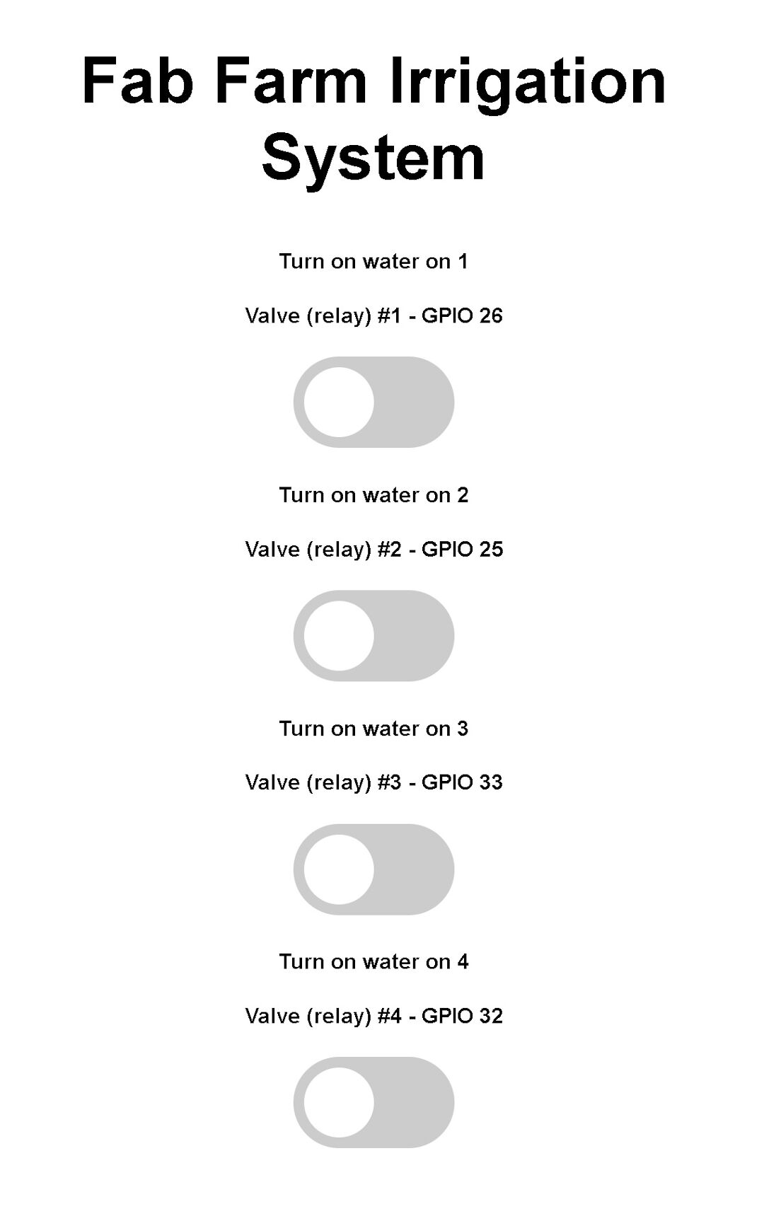
The appearance and code right now are pretty much the same as in the Random Nerd Tutorials website for relays controlled with an ESP32.
The main difference from the original code is that it runs on PlatformIO for VS Code, and it also uses a separate folder structure for the HTML file, which is written to the SPIFFS of the ESP.
14th of June, 2020
After this whole personal breakthrough, I decided I need to start the code from scratch and use only the general algorithm of the current irrigation system installed on the farm. The reason is that the code is too messy and repetitive; the approaches found in yesterday's sources made me realize it's faster to add the features to the latest code one by one than to recode everything from the code currently running on the farm.
Today I will attempt to add updated information like temperature and humidity. Again, I am basing it on the work of Rui Santos on this page about a weather station. With this approach, I believe I will also be able to include the time of day using an RTC clock.
The schematics for connecting the DHT22 are from his website:
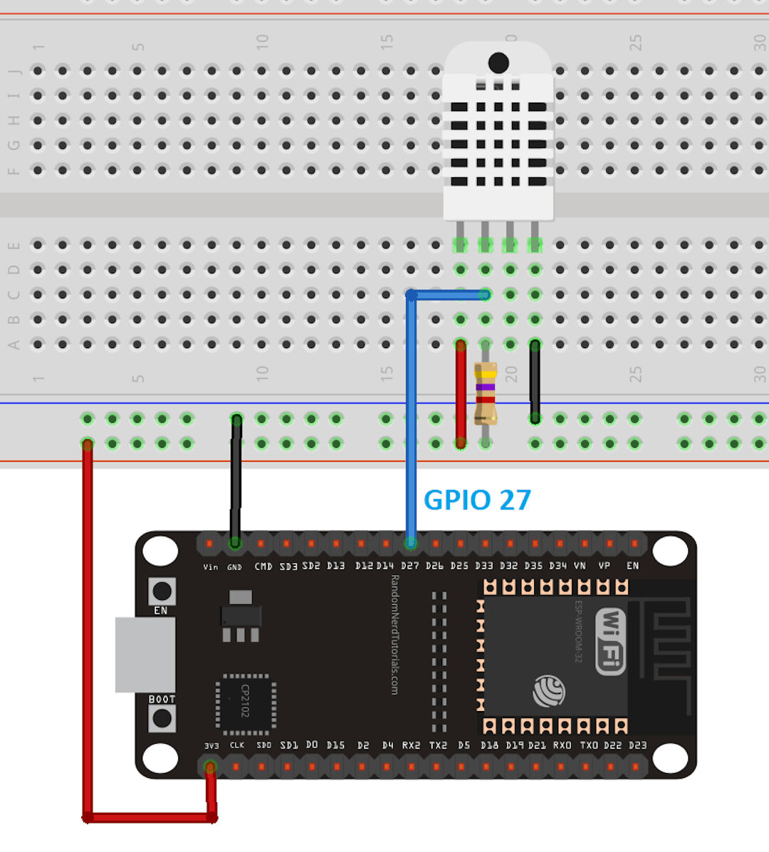
It uses a 4.7 kOhm resistor as a pull-up.
After some work, this is how the page looks:
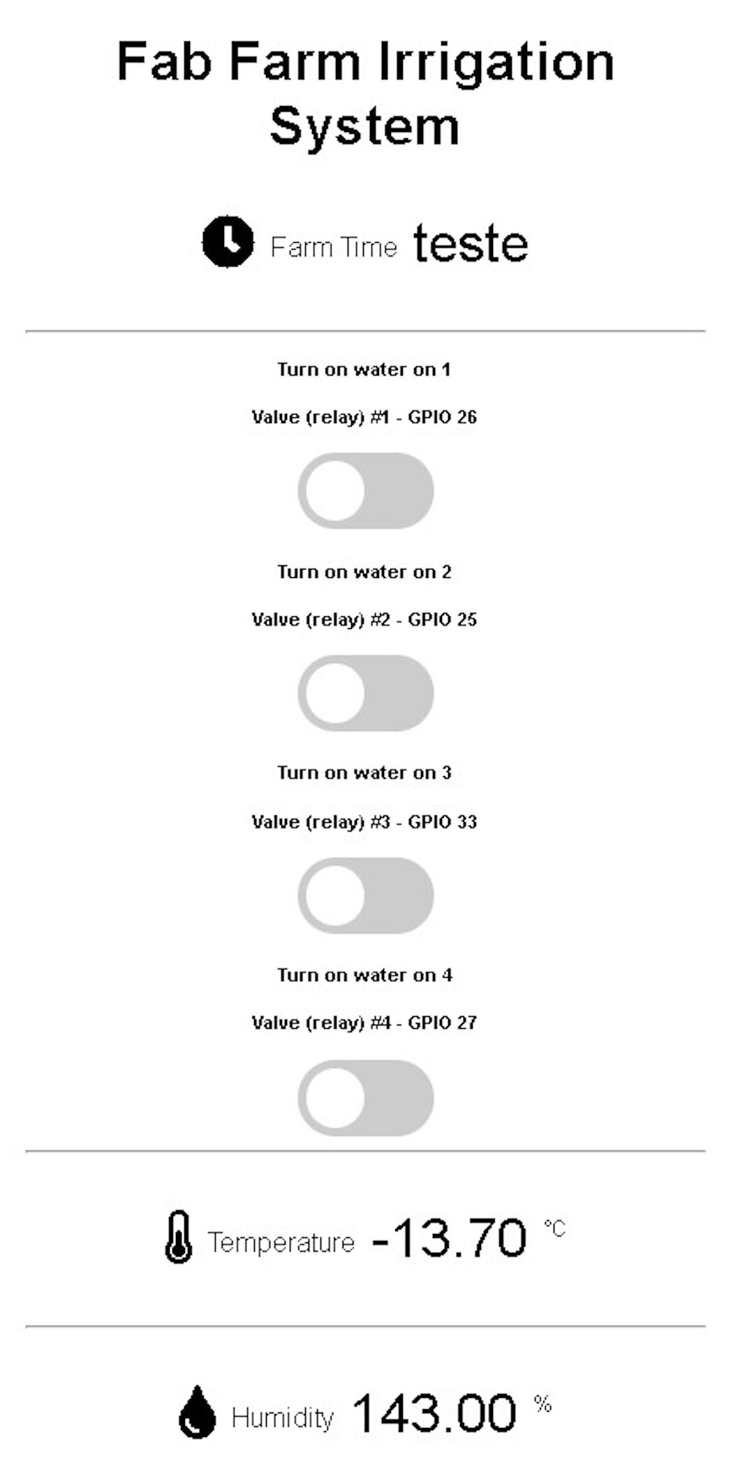
I believe the reason the temperature is now negative is that the temperature and humidity sensor is either faulty or my wiring is a bit loose. I believe once I mill my own board and solder everything, instead of plugging it into a breadboard, this will be more reliable. Anyway, I am getting the values and I am able to show them on the web interface.
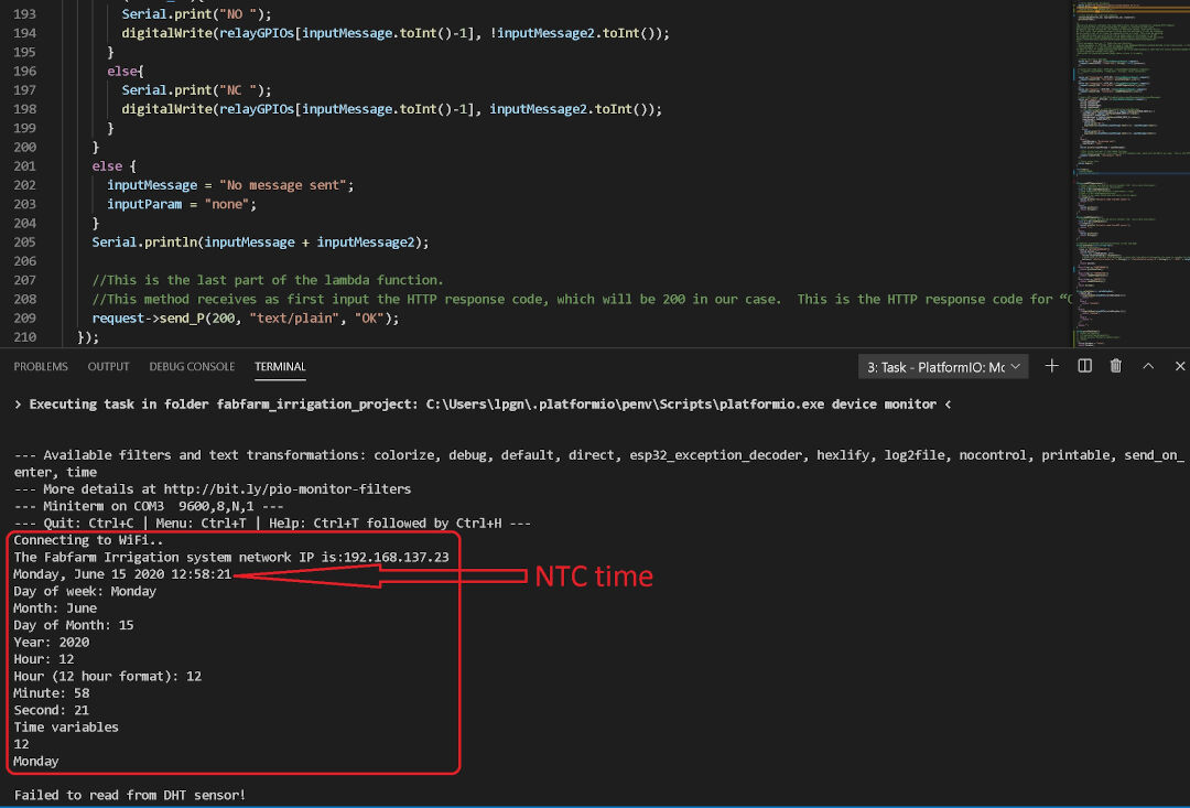
On the serial monitor I am currently able to display the Internet time as well as the network information; now I need to find a way to get the time value and display it in the web interface. Currently I am sending the word TESTE through the code, and that is being displayed instead of the time.
15th of June, 2020
Today I will focus on getting the time displayed in the web interface and perhaps create a function to turn on the relay at a specific set time.
20:44 Update:
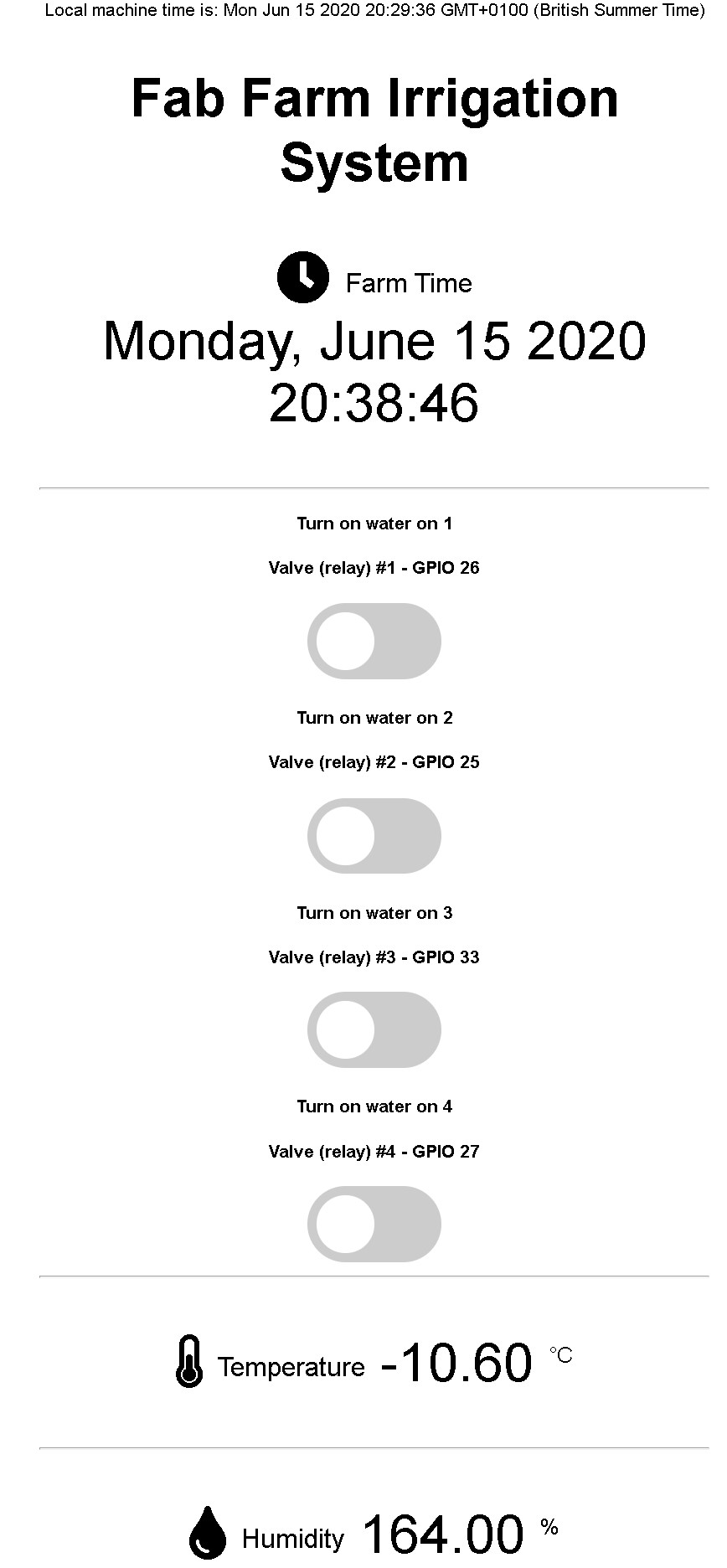
- After the whole day trying, I was able to display the machine time and the irrigation system (ESP32) time.
Now the interface looks like this:
When I grow up I want to be a programmer :-) and not spend an entire day on something someone puts together in a few lines!
My struggles were ended by a saint with this answer on Arduino Stack Exchange.
Here follows the original function posted there:
void printLocalTime()
{
  time_t rawtime;
  struct tm timeinfo;
  if(!getLocalTime(&timeinfo))
  {
    Serial.println("Failed to obtain time");
   return;
  }
  char timeStringBuff[50]; //50 chars should be enough
  strftime(timeStringBuff, sizeof(timeStringBuff), "%A, %B %d %Y %H:%M:%S", &timeinfo);
  //print like "const char*"
  Serial.println(timeStringBuff);

  //Optional: Construct String object
  String asString(timeStringBuff);
}
With minor modifications, changing it from a void function into a String function and adding a return that I named "timeAsAString":
//this function was found here https://arduino.stackexchange.com/questions/52676/how-do-you-convert-a-formatted-print-statement-into-a-string-variable
//I did a minor change so instead of a void function it now returns a string to be used to show time in the webinterface
String printFarmTime()
{
  time_t rawtime;
  struct tm timeinfo;
  getLocalTime(&timeinfo);
  char timeStringBuff[50]; //50 chars should be enough
  strftime(timeStringBuff, sizeof(timeStringBuff), "%A, %B %d %Y %H:%M:%S", &timeinfo);
  //print like "const char*"
  Serial.println(timeStringBuff);

  //Construct to create the String object
  String timeAsAString(timeStringBuff);
  return timeAsAString;
}
Warning: this version drops the if(!getLocalTime(&timeinfo)) check, so if NTP has not answered yet it formats an empty (garbage) time. Keep the check and return something like "time not set" when it fails.
So, with that out of the way, I will try to create the functions to turn the relays on and off according to the scheduled time. Let's see if I can finish it today...
16th of June, 2020
No, I did not work on it, I was tired, so today I made a few sketches.

In this sketch I show what the package shape is going to be and what the web interface is going to be like as well.
I am also reading about String as well as its manipulation.
I could follow an approach of splitting the dates as a String and converting them to other types of values for the operations I intend. Another possibility is to get the data in the type I need from the beginning. Although I like the latter better, I haven't found a solution for it yet, as I don't understand the getLocalTime() function well yet. So I will read more about it now.
Wait... that was fast! I found a post that answers my need. Here it is:

So I based myself on the post above to create the function below:
      int gimeTime(char what) {

          int OnlyYear;
          int onlyMonth;
          int onlyDay;
          int onlyHour;
          int onlyMin;
          int onlySec;

          struct tm timeinfo;
          if(!getLocalTime(&timeinfo)){
            Serial.println("Failed to obtain time");
            //return;
            }
          onlyHour = timeinfo.tm_hour;
          onlyMin  = timeinfo.tm_min;
          onlySec  = timeinfo.tm_sec;
          onlyDay = timeinfo.tm_mday;
          onlyMonth = timeinfo.tm_mon + 1;
          OnlyYear = timeinfo.tm_year +1900;

          switch (what) {
            case 1:
            return onlyHour;
            break;
            case 2:
            return onlyMin;
            break;
            case 3:
            return onlySec;
            break;
            default:
          // if nothing else matches, do the default
          // default is optional
          break;
          }
      }
Warning: the default case ends without a return, so the function returns an undefined value for anything other than 1, 2 or 3 (put return -1; there). Same when getLocalTime() fails: with the return commented out, it goes on reading a timeinfo without a valid time.
That's it, now I can finally work on the timer scheduling code. By the way, I spent almost the whole day trying to find a simpler way to get the times, but just couldn't, as I am struggling to understand the (struct) type. Well, maybe I will go back to it in the future, but for now it's good.
17th of June, 2020
Super early morning update:
I am very frustrated, I need to move to the atoms and wrap up the bits part of my project.
Late at night, the most I moved forward was making a small function to turn off the relays; here it is:
        int zoneStartStop (int zone, int startStop){
        int waitTime = 1000;
        if (startStop == 1){
        digitalWrite(relayGPIOs[zone], startStop);
        Serial.print("*** Zone Valve");
        Serial.print(zone);
        Serial.println("ON ***");
        delay(waitTime);
        digitalWrite(pumpGpio, startStop);
        Serial.print("*** Pump turned ON ***");
        }
        else{
        digitalWrite(pumpGpio, startStop);
        Serial.println("*** Pump turned OFF ***");
        delay(waitTime);
        digitalWrite(relayGPIOs[zone], startStop);
        Serial.print("*** Zone Valve");
        Serial.print(zone);
        Serial.println("OFF ***");
        }
        }
(Code corrected later: when stopping, the pump now turns off before the valve closes, so it never pushes against a closed valve, and the message says OFF.)
It's a start, but not there yet, and I haven't tested it.
Morning Update:
So I will now look into another example for setting a timer, again by Rui Santos, it's here; maybe I can change it a bit, integrate it into my code and add a start time, then use the slider to set how long, in minutes, it will run. That would be enough for now!
So far I have made the code compatible with PlatformIO, and I also separated the index.html file from the C++ code and placed it in its own folder, to be saved by the save-to-SPIFFS routine that I described on 13/06/2020.
References
Footnote
Links: