Lagos, Portugal

+351

  • Follow Us :

  • Email us

Algarve FabFarm

  • Home
  • Students
  • Instructors
  • Group Assignments
  • Machine Building

How to make almost anything

Fab Academy 2020

Computer Controled Machining


Objectives:


  • Test runout
  • alignment
  • speeds
  • feeds
  • toolpaths for your machine
  • Document your work (in a group or individually)


    Files

  • Artcam holes template
  • Artcam holes gcode
  • Solid works template
  • hsm gcode template

  • Our Machine:


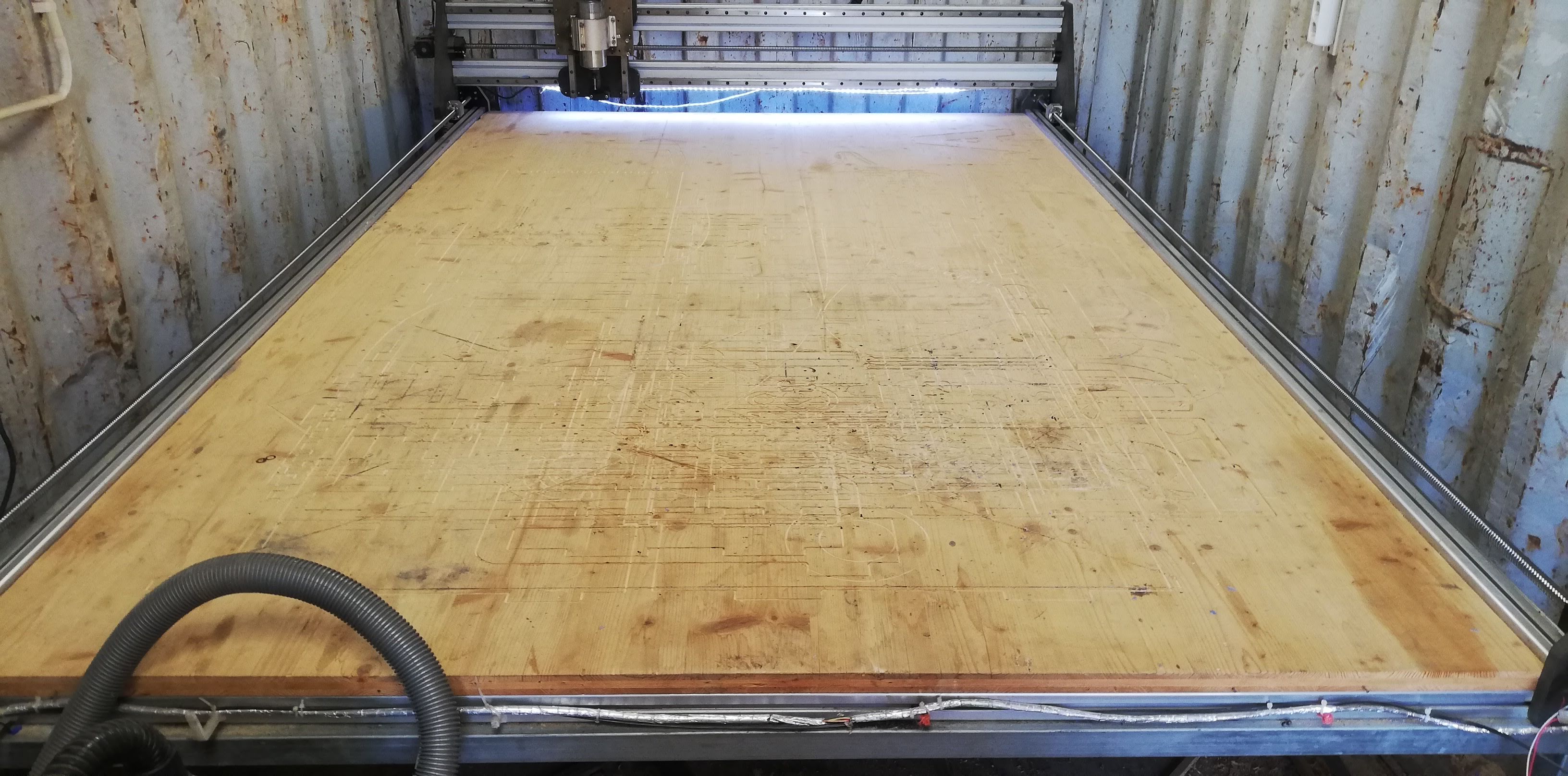
    Our CNC is a DIY machine made by Lucio as one of his Fabacademy's Final Projects ideas.

    It measures approximately 3000mm x 2000 mm. It is fitted in one of the containers in the farm.

    We started the group task by researching other fablabs and the documentation that was most inspiring for us was from Berytech FabLab it showed a lot of theory about milling with a CNC as well as the tests performed.

    We extracted a few important points that will be used in this task. If you want to go a little deeper on the theory I suggest a read on their website as it's a nicely written without being too technically heavy.


    Testing our CNC


    test run-out, alignment, speeds, feeds, and toolpaths for your machine

    1. Spindle runout: is the inaccuracy of the spindle in relation to its axis. In general it will cause a role to be bigger than the tool used and most important it will decrease the life of the tool a LOT!
      • References:

        youtube video from At-Man Unlimited Machining channel and this link from the CNCcookbook website.

      • Procedure:

        In order to test it we will be using a dial indicator:

        1. fix the dial indicator to the spindle holder with the magnetic attachment, if not possible just fix the holder to a stable surface.
        2. rotate the spindle slowly and take the measurement
        3. next step is to take the measurement from the mill bit smoth area and take a note on the runout

        First runout test

        Your browser does not support HTML5 video.

        Second runout test

        Your browser does not support HTML5 video.

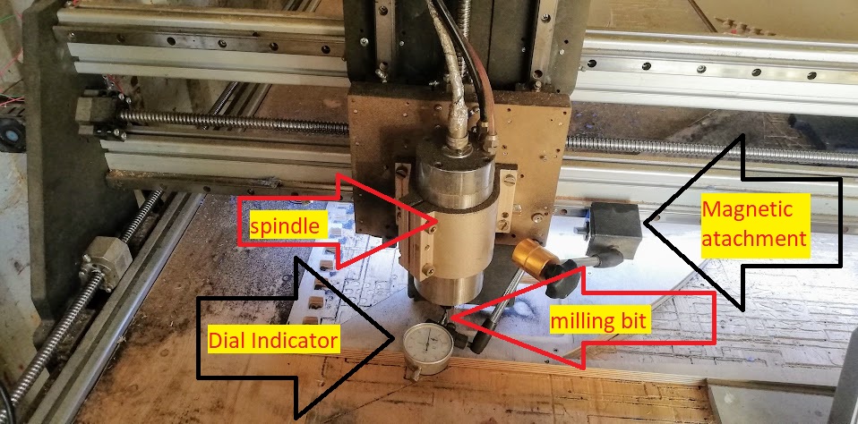
        Depending on the results you will have to fix the spindle, what could mean replacing it even I had to fix my spindle before and the procedure was documented on the PCB production assignment.

        My result was quite acceptable, around 0.01mm.

    2. Alignment:
      • References: youtube video from cncrouterparts channel
      • Procedure 1: Parallelism between the tracks. For this procedure I will be using a level, a string, tape, and a wrench.
      1. First I will try to level the CNC as much as possible. I will do this using a level and by turning the machine foots until I believe it is acceptable. The most important thing is not the level put the parallelism between the tracks of the Y axis. The objective is that the gantry moves along the table plane, the next step will be the fine tunning.
      2. Checking the level.

        Adjusting the foot with the wrench.


      3. Fine tunning: With a String attached to all the corners I will check the string and turning the foots until the string touch each other in the middle.
      4. Checking the level again with the string attached to the corners.

        String almost touching in the middle needs 2 mm adjustment.

        Your browser does not support HTML5 video.

        Showing the alignment procedure:

        Your browser does not support HTML5 video.

      5. When I am happy with the result I lock the nut to the foot so it does not move again.
      6. String touches each other.


      • Squaring the gantry axis in relation to the table. For this procedure I will be using a piece of metal.

        the objective is the gantry (y axis is perpendicular to the X axis.

      1. With the computer interface I will bring the gantry near me and try to fit the tool between the spaces. The procedure is adapted from here.The tools used are: scrap piece of MDF, long construction square, smaller square, 5 mm end mill, 4 broken 5mm base end mills.
      2. Your browser does not support HTML5 video.

      3. With the steppers disabled using a piece of metal I will make sure both sides of the CNC are at an equal distance.
      4. Your browser does not support HTML5 video.

      5. Next I prepared a gcode to drill 4 holes in the shape of a square 180mm. Original artcam file here
      6. Here I show the CNC making the holes.
      7. Your browser does not support HTML5 video.

      8. Next I measure the diagonals from corner to opposite corner of the square, they should be the same, but my first attempt is not acceptable. I redo off camera the procedure in the video letter (i)
      9. Your browser does not support HTML5 video.

      10. I mark the original holes to avoid confusion offset the origin off the CNC by a random number and redo the Gcode.
      11. Your browser does not support HTML5 video.

      12. Now the results are acceptable and I have a squared CNC
      13. Your browser does not support HTML5 video.

    3. speeds, feeds and toolpaths
      1. Tooling:
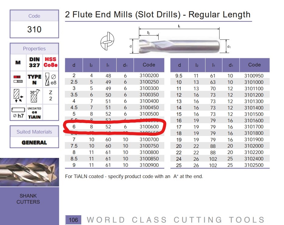
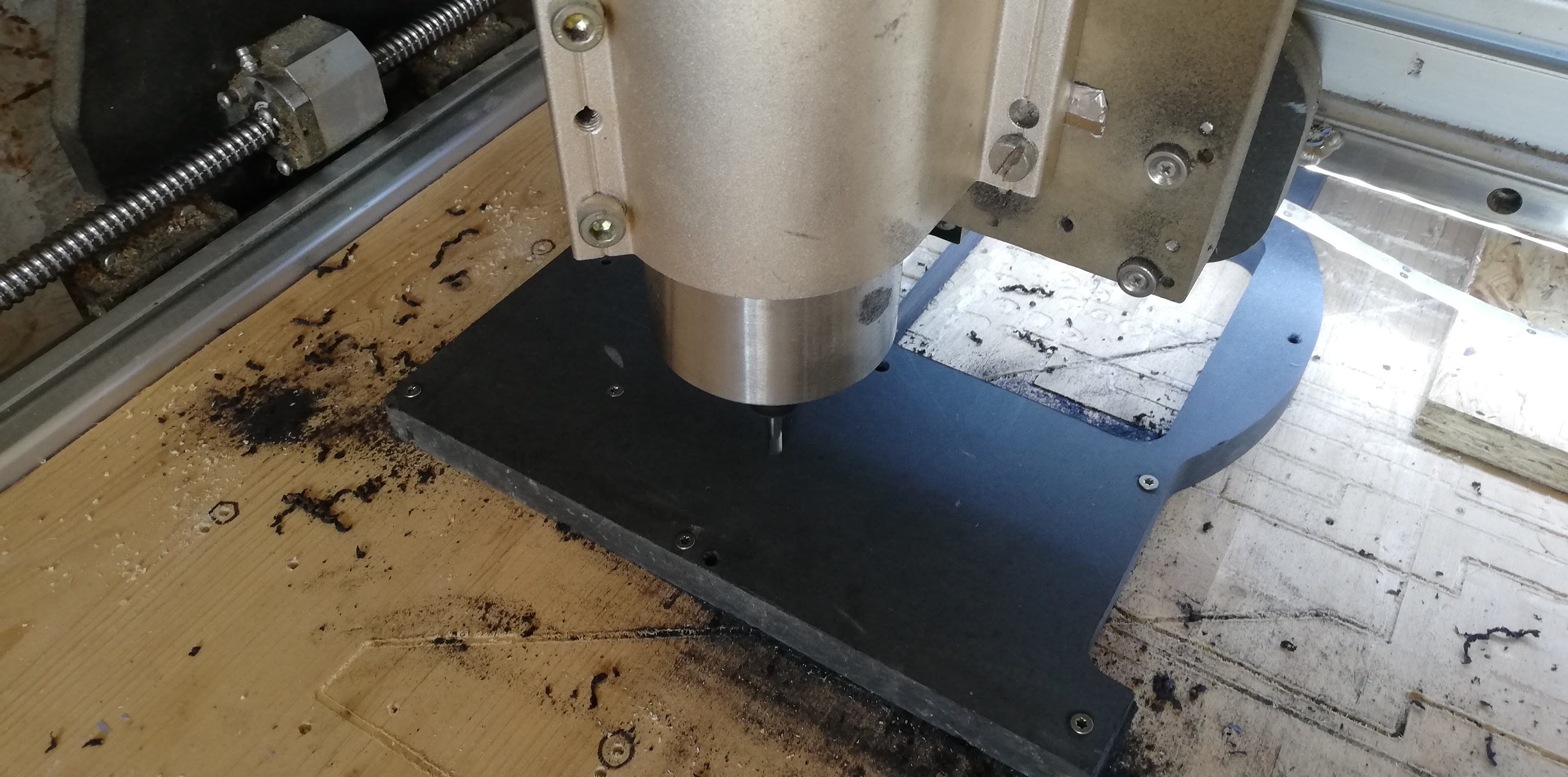
      2. We will be using the following tools to perform our tests: 6mm 2 flutes spiral flat tip end mill.


      3. Speed and Feeds:
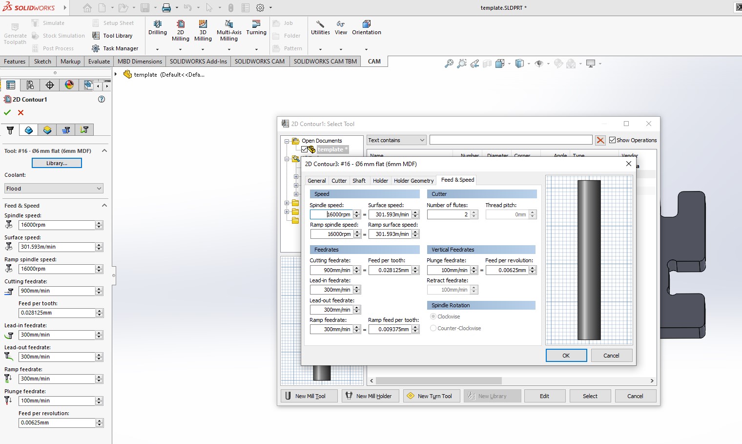
      4. We calculated the speeds based on experience with the help of HSM on solidworks. When you create or change a tool it calculates with its internal formulas feedrates, surface speed and ramp speed, etc. For this test I used 900mm/min for cutting speed and 300mm/min for ramps and etc. Well in the middle of the test in the CNC interface I increased speeds as it was slow for what I was used and I ended up using for the rest of the test 2100 for cutting feedrate and 700 for ramps.


        Results


        1. Cutting the template


        2. Template cut still attached on CNC table


        3. On this picture I tried inserting the small piece to its hole that is rotate. The result is it is quite aligned and squared but did not fit completely.


        4. Here on the Y axis the expected result was 19mm and I measured 18.95mm


        5. Here on the X axis the expected result was 10mm and I measured 9.75mm


        6. Here on the Y axis the expected result was 10mm and I measured 10.2mm, most likely because I restarted the code and I notice the second time it went thru it cut a small amount on the Y axis


        7. Here on the X axis the expected result was 10mm and I measured 10.1mm. Now I am starting to believe my end mill accuracy is about +-0.05mm


        8. Here on the Y axis the expected result was 41.27mm and I measured 41.2mm


        9. The small piece will enter the small gap.


      Conclusion

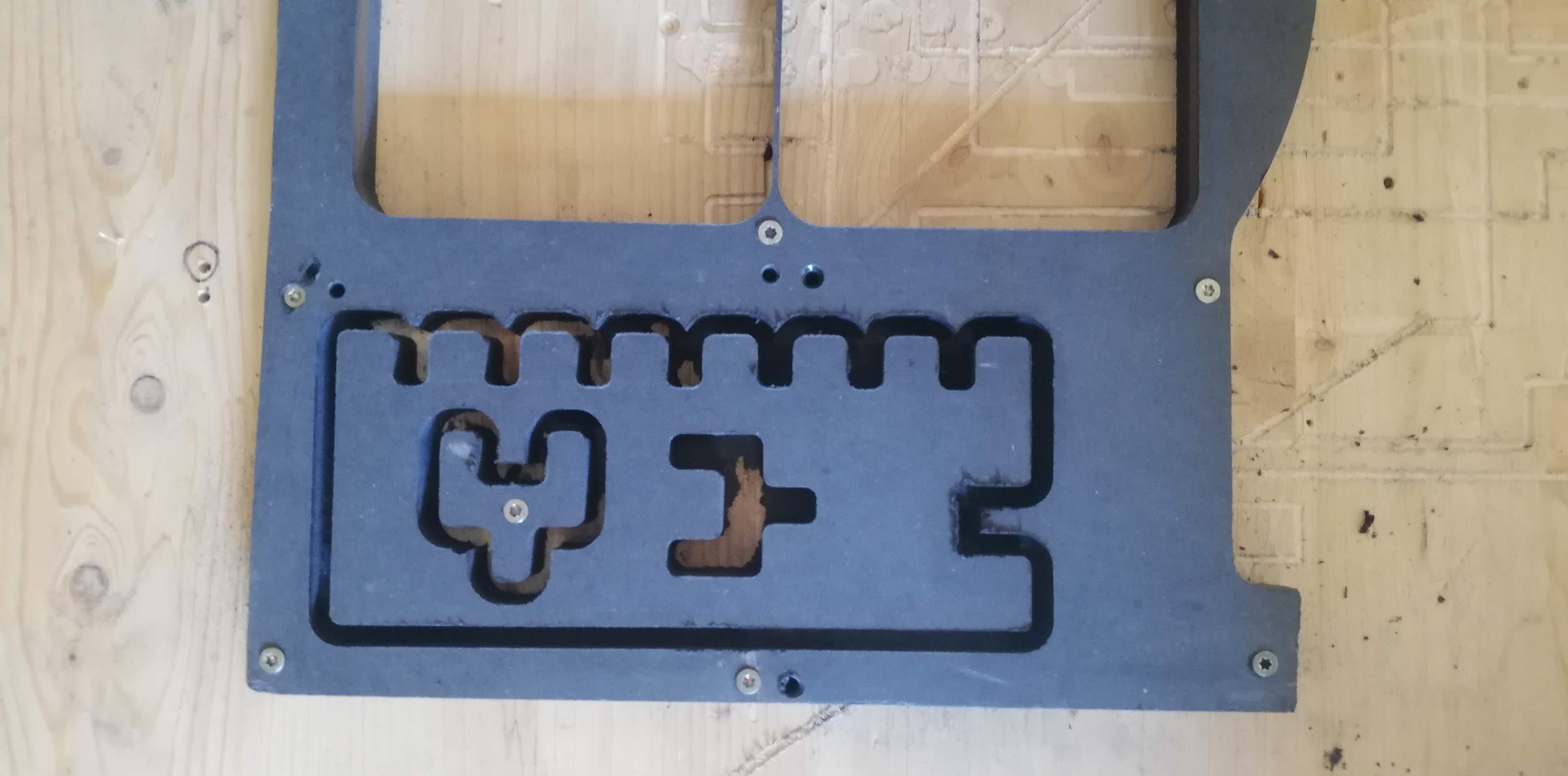
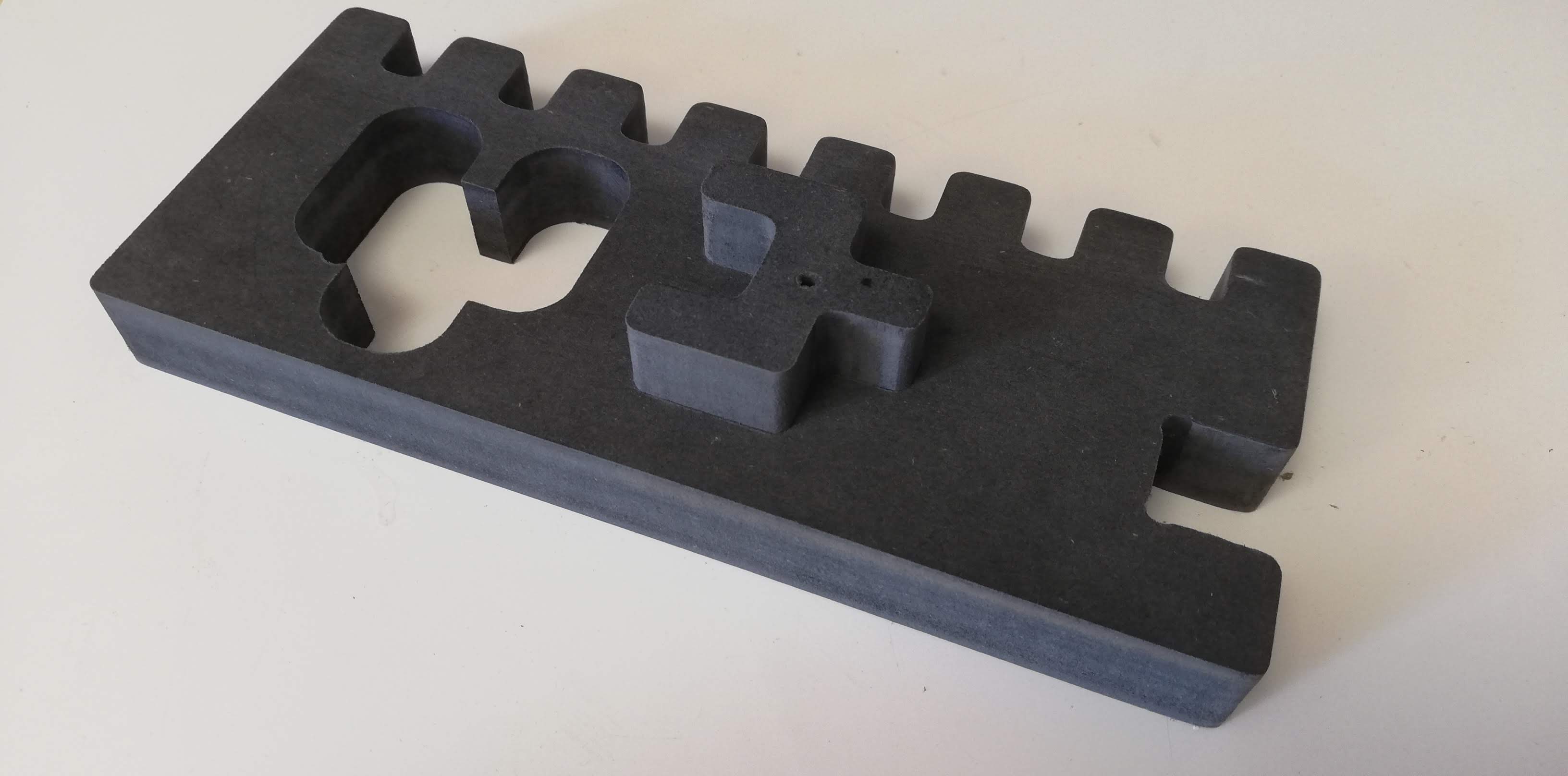
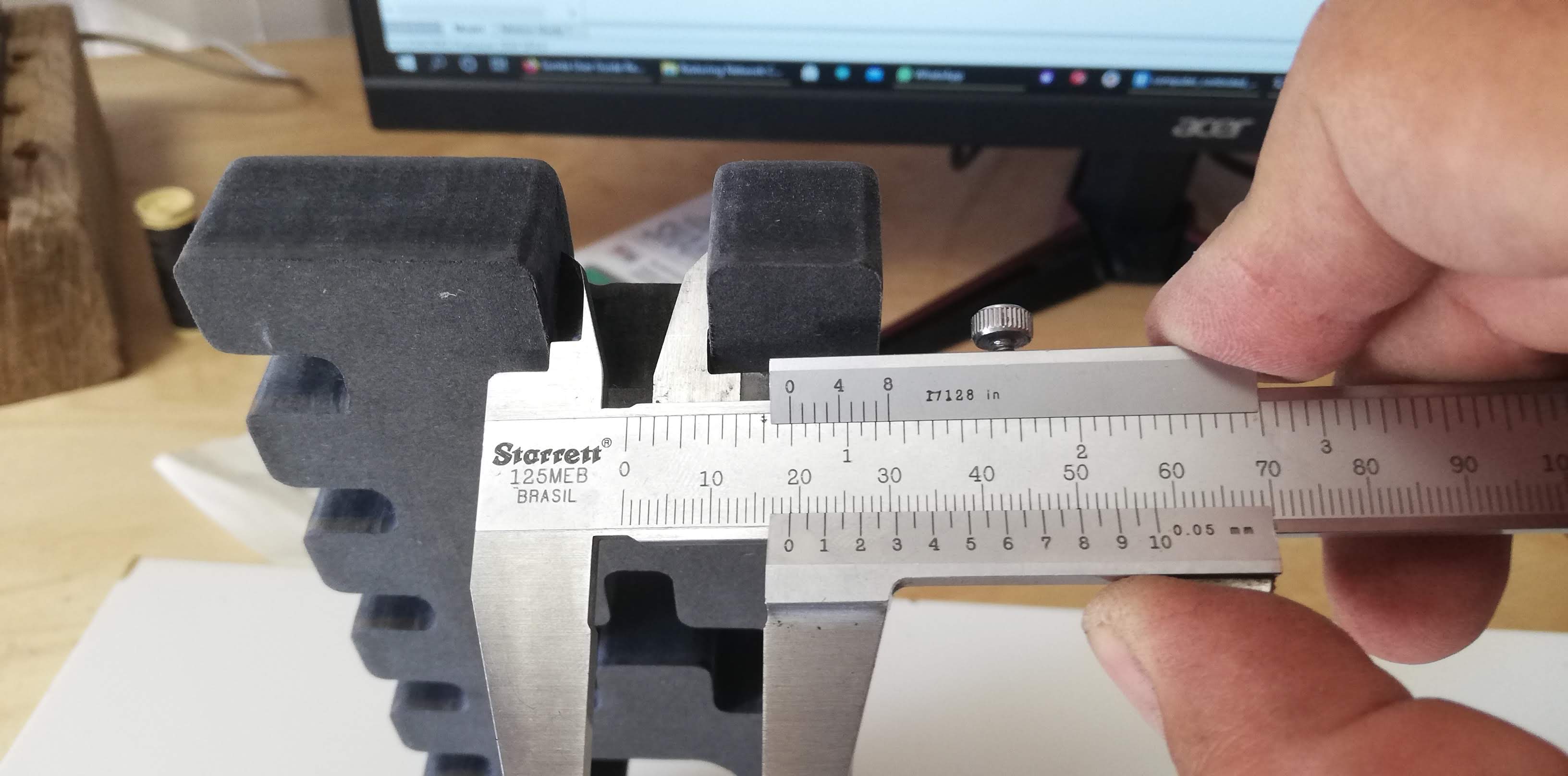
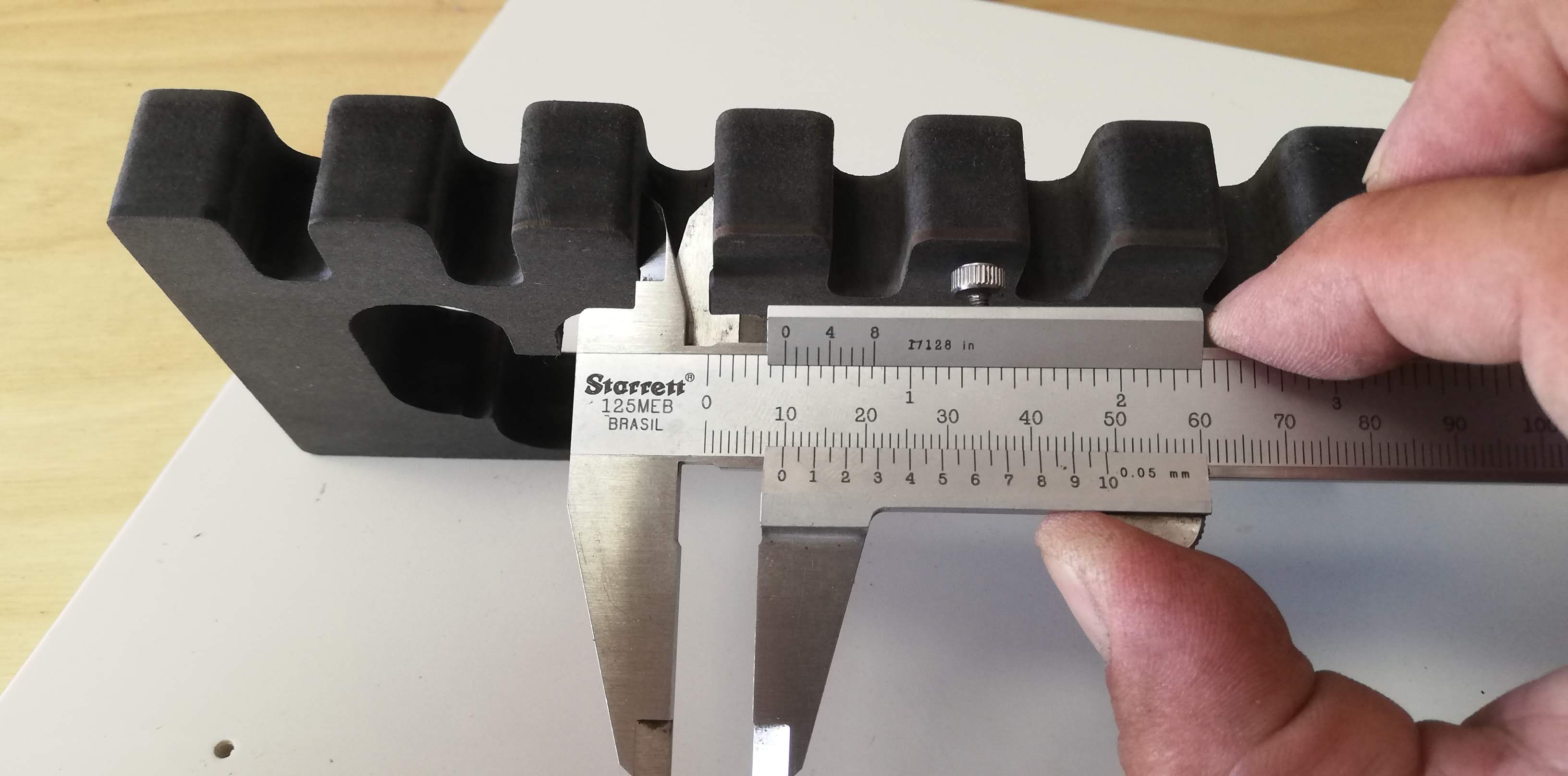
      My CNC is quite precise for wood work but it needs attention on the daily calibration of its squareness as it is prone for loss of steps, I would recommend an off set from 0,05mm to 0.1mm to ensure fit without struggle.

    Group Assignments

    news image
    Computer controlled cutting
    news image
    Electronics production
    news image
    3D scanning and printing
    news image
    Electronics desing
    news image
    Computer controlled machining
    news image
    Embedded programming
    news image
    Molding and casting
    news image
    Input devices
    news image
    Output devices
    news image
    Networking and communications

    Machine building assignment

    news image
    Laser Cutter

    2020, Algarve Fabfarm | HTML templete Design by W3layouts.