Computer-Controlled-Machining(WEEK 8)
Individual Assignment:
- Make (design+mill+assemble) something big
Group Assignment:
- Test runout, alignment, speeds, feeds, and toolpaths for your machine
IMPORTANT NOTE : ALL OF MY IMAGES ARE POP UP IMAGES , IF YOU HAVE ANY PROBLEM READINGS THOSE IMAGES , PLEASE CLICK ON THEM AND THEY WILL ENLARGE AUTOMATICALLY AND YOU CAN READ THEM EASILY
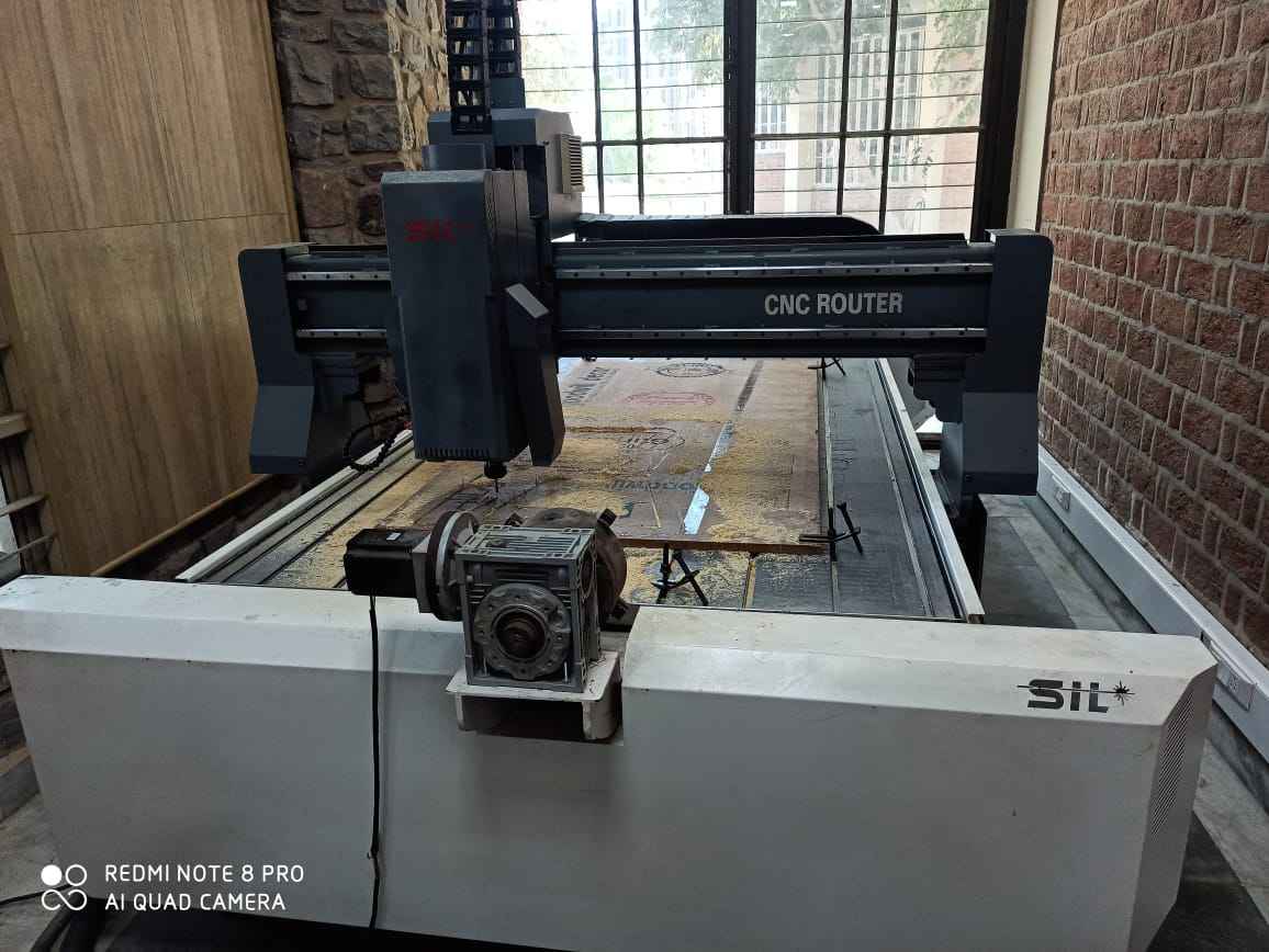
Machine in our lab
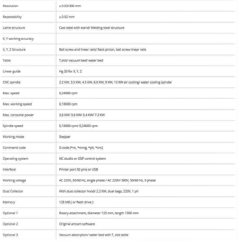
SIL 1325 - CNC Wood Router Machine
* CNC router finds application in architectural mill work, aluminum and metal composite cladding, signmaking, graphics & print finishing, wood working, plastic fabrication, metal fabrication, foam packaging, die
maker, duct maker, solid surface, MDF cutting, 3D panel mold making, 3D plastic trimming, residential & commercial constructions & many more We provide double spindle for faster working performance, and rotary
option (optional)
* SIL built CNC router for manufacturers who process large volumes of cladding materials and rely on speed and efficiency
* CNC router machine has built in X, Y axis drive system. A single-piece, heavy-duty steel frame, coupled with a helical rack drive system and high tolerance bearing components, delivers high-accuracy motion
and quality cutting Optional 2.2KW / 3.5 KW / 4.5KW / 6.0KW / 9KW / 12KW spindles of various powers Handheld DSP Controller to set job parameter.
* Water cooled / air cooled spindle for longer life & guaranteed machine performance.
* Available in many sizes from small to large and Special size table. From 4 x 4ft ~ 7 x 21 ft. Vacuum table or aluminum T- slot extrusion table. Automatic lubricating system. Mist cooling system. Machine
moving feet, Manual tool changer spindle.
* Excellent speed, efficiency, high precision CNC engraver router machine built in X, Y Axis drive system rack and pinion with 25 mm square linear rails achieving high positioning, motion accuracy & longer
life. Working Table with aluminum T-slot and PVC sheet for protection of worktable which ensures for longer life.
For more information you can visit SIL website throgh this
Software used
Aspire

Aspire is a powerful but intuitive software solution for creating and cutting parts on a CNC router. There are tools for 2D design and calculation of 2D toolpaths such as Profiling, Pocketing, and Drilling as well as 2.5D toolpaths including; V-Carving, Prism carving, Moulding Toolpaths, Fluting and even a decorative texturing strategy.
Aspire provide 3D design tools which enable you to create your own 3D relief models and machine them with 3D machining strategies. Aspire’s unique 3D modeling tools coupled with the comprehensive set of 2D design
and editing tools make it easy to create your own 2D and 3D parts from scratch as well as the ability to import and edit external 2D and 3D data.
As you know Aspire vectric is an paid software you can only have 7 Day trial period from official site so you can go download it by clicking on this
Getting started with software

* Click on the option "Create a New file".
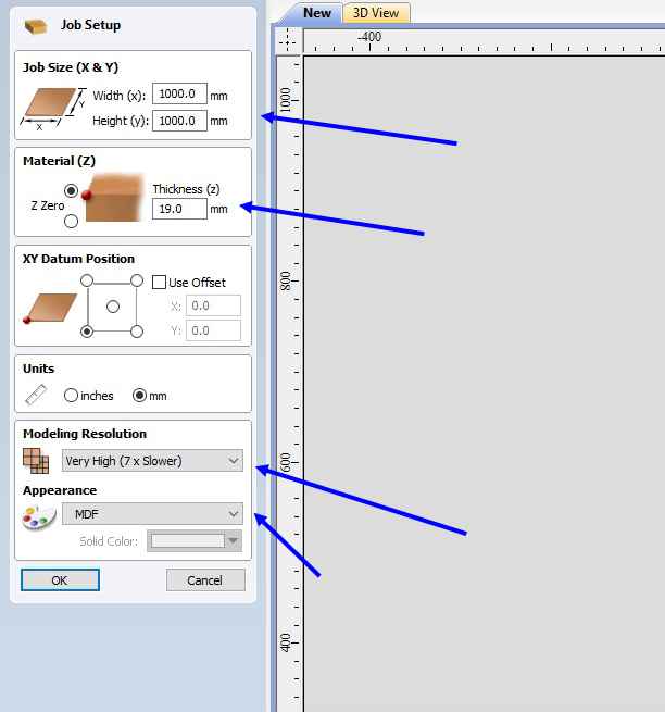
* After that input the parameter of the material which is available in lab Parameter's are
1. Material thickness
2. XY Datum Position
3. Units
4. Modelling Resolution
5. Appearence
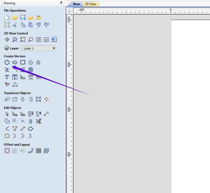
* Select circle and give radius
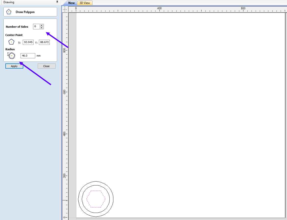
* Select hexagon
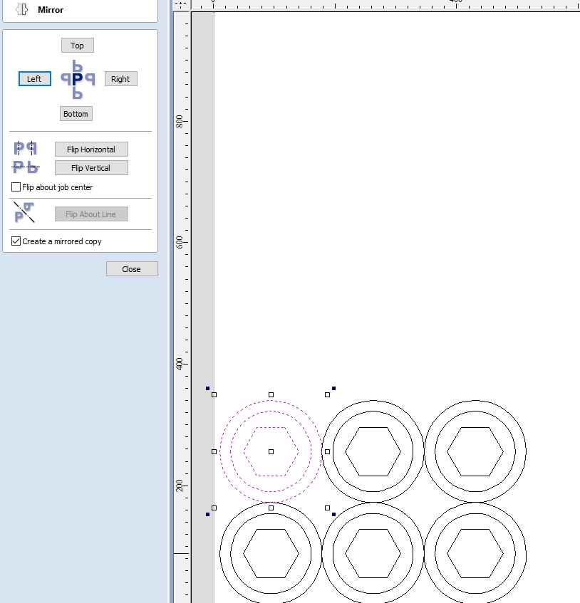
* Use mirror command to create multiple same object.
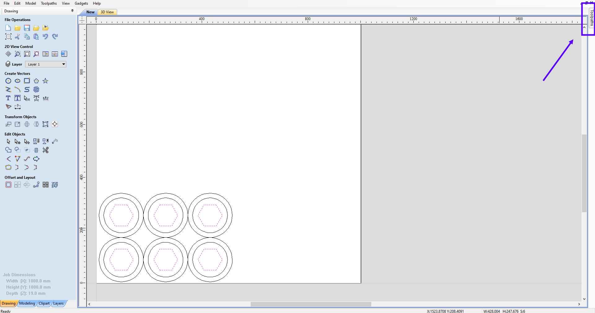
* Steps to creat cnc program for the vector files.
* Click on tool path at top left hand side
* Click on profile toolpath
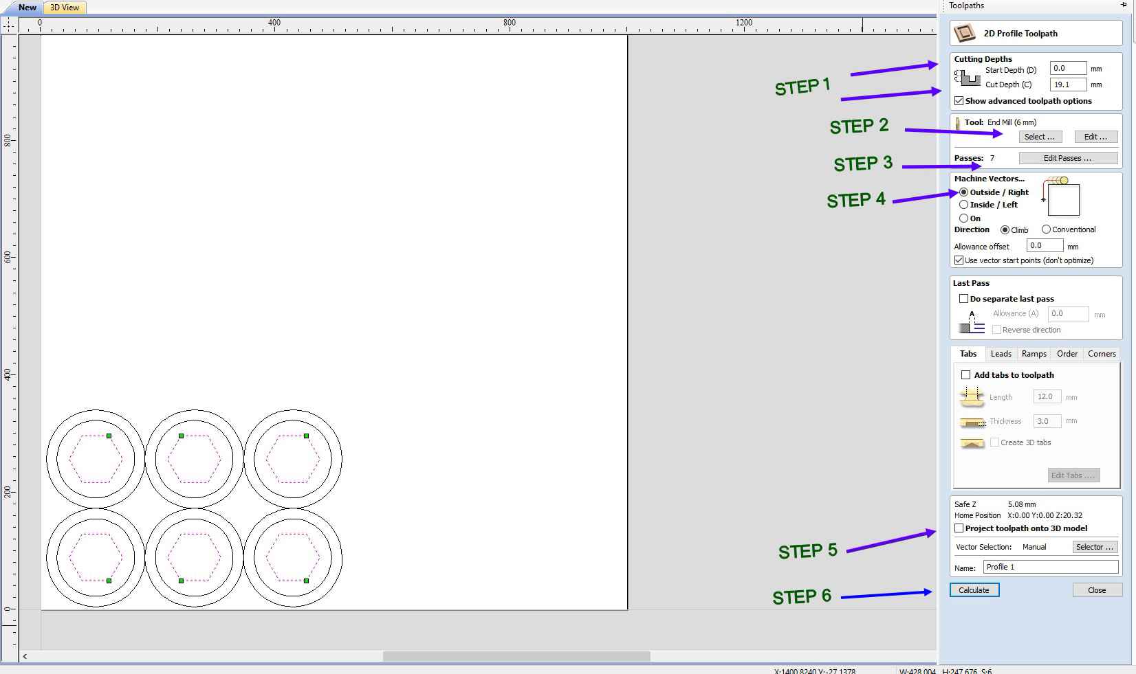
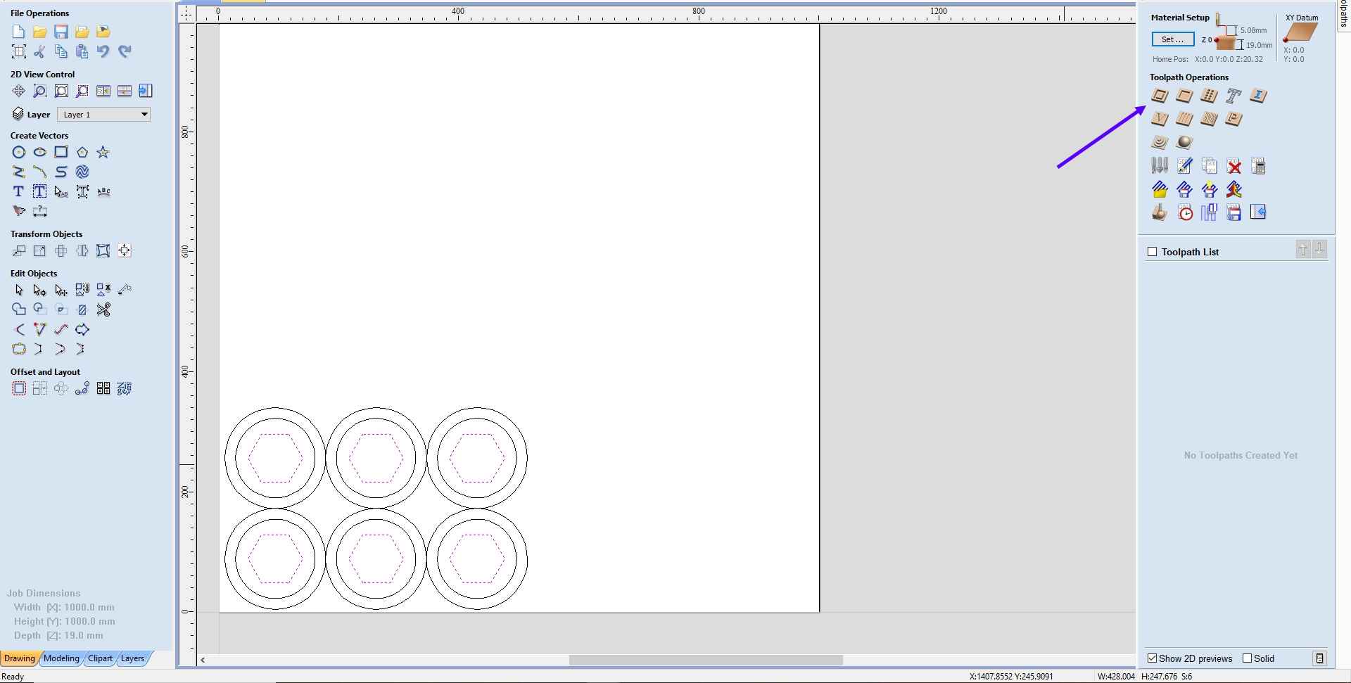
* Basic steps for generating g-codes
1. Step 1: Give the initial and final depth.
2. Step 2: Enter the tool diameter.
3. Step 3: Enter number of passes.
4. Step 4: Enter machine vector which you require for your job.
5. Step 5: Click on Project toolpath onto 3d model
6. Step 6: And finaly click on calculate
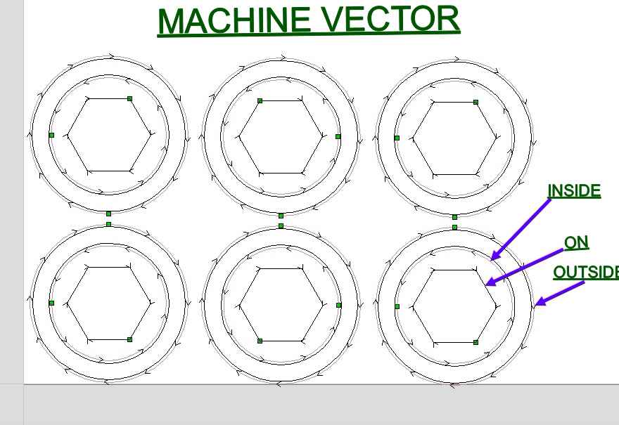
* I have provided 3 diferent machine vector for one drawing as you can see
Getting started with Machine
6 UNBREAKABLE SAFETY RULES FOR CNC MACHINERY SAFETY
Learn what to do, and what not to do, to keep yourself safe when you operate CNC machinery. Computer numerical control (CNC) machines are generally safe. But worker misuse can easily jeopardize their safety. That’s why it’s important for their operators to know exactly what they should – and should not – do.
When your workplace is safe, you’re able to attract the best employees. Worker satisfaction and productivity stay high. Turnover and costs related to workplace accidents stay low. So here’s what to look for to keep your workers safe
1. Only Operate CNC Machines You’ve Been Trained to Use
Sounds obvious and simple, but some companies do allow untrained employees to operate CNC machinery with little or no training. Many accidents
do happen this way.
2. Always Have at Least One Person Observing the CNC Machine
For some, it’s tempting to leave the room while the programmed CNC machine does its work. Most likely, nothing will go wrong. But once
in a while, CNC machines break or don’t work right. It happens. They’re machines. And that’s when injuries can happen too. So make sure you have every CNC machine under observation by at least one person.
3. Always Do These Things Before Operating Your CNC Machine
Here’s a brief list of to-dos:
* Ensure the tools are sharp and free of cracks
* Double-check to make sure all tools are set correctly
* Double-check that you have set the right tool data for the program
* Test tools before every new use
* Examine seating surfaces for cleanliness before installing new tools
* Set the spindle direction correctly for right and left-handed operators
* Only use tools within manufacturer limits and tighten them to their recommended torque
4. A Few Things Never to do Before Operation
Pretty simple and straightforward here. Never use blunt, cracked, or chipped tools. If you notice tools with damaged tips, don’t use those either.
5. If You Use a CNC Router…
Before you operate a CNC router, make sure there aren’t any screws in the path of the bit. At best, the bit will get broken and the screw will get embedded into your project. However, in some cases the
screw can shoot off and hit you or another worker. If, during operation, you notice anything unusual with the bit, hit the pause button, or the red emergency button for immediate shutdown. Fix the problem before
you begin operating again.
6. Always Make Sure You’re Mentally Focused
If you’re not feeling well and it’s hard for you to concentrate because of a sickness, don’t use CNC machinery. Supervisors, send your workers home if you notice them behaving unusually. Workers, notify
your supervisors if something doesn’t seem right. Better to miss a few hours of work that cause an injury to yourself or someone else. And, better to leave work than it is to break the machine and cause costly
repairs and downtime. Do those things – and you and your workers will stay safe.
SOME PRIOR SAFETY EQUIPEMENT REQUIRED

1. SAFETY GOOGLES: While working on machine there is an chance that some chips can come towards you so protection of eyes is of atmost impoertance
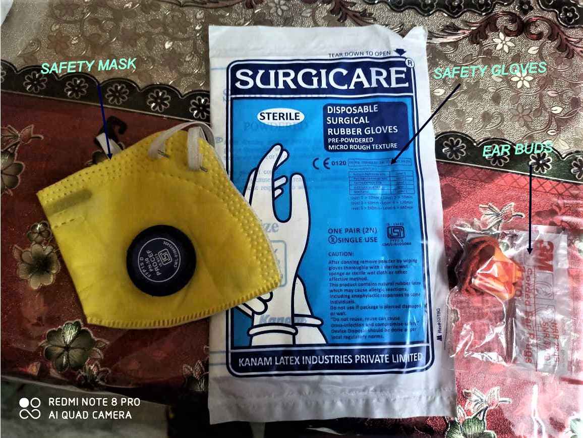
2. SAFETY MASK : There is an chance that during operation lots of dust particle will be scater in air and inhalling them can be injurious to the health of the person who is working on the machine at that
time so its highly recommanded to wear an face mask.
3. Ear buds : Machining ang Cutting process can create a lots of noise which can create headache in long term so please try to wear these ear buds during the process.
4. SAFETY GLOVES: After the part is cutted the are high chances that some piece of wood can pierce our hand during removal of cutted part so please try to wear these gloves , to prevent any type
of injury
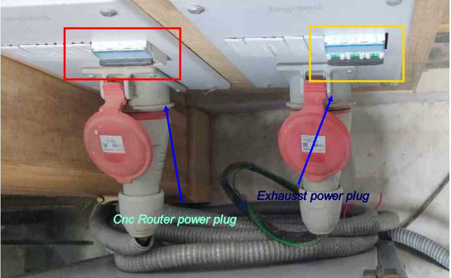
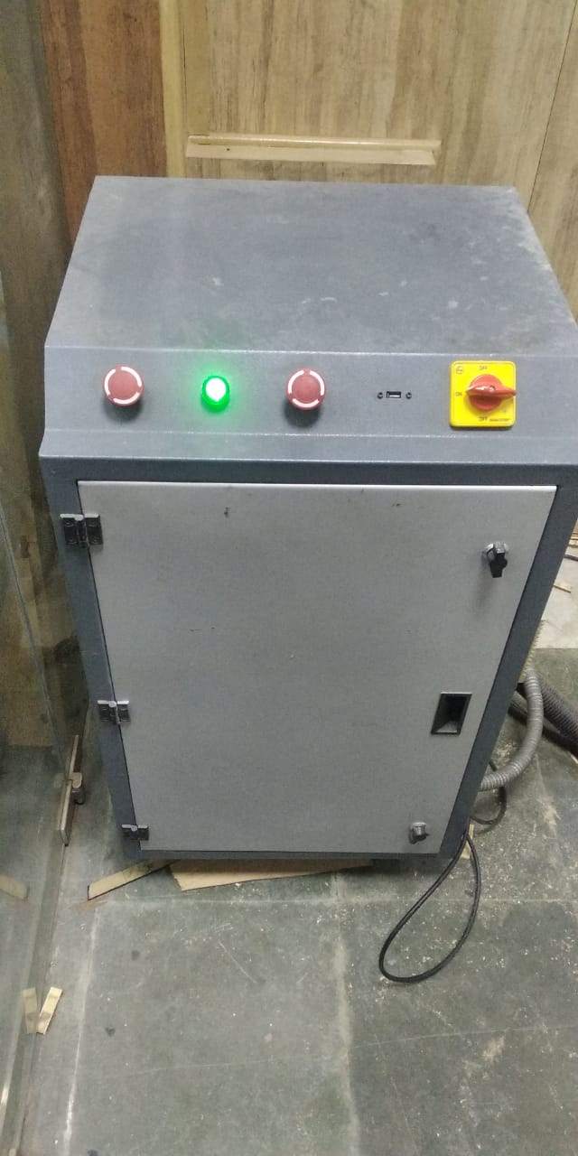
* Please check in the back of the machine
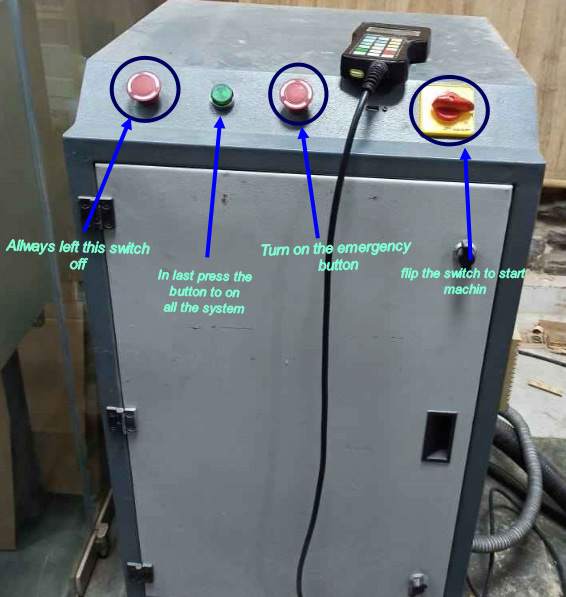
* After purforming all the steps , you can see the start button lighted up.
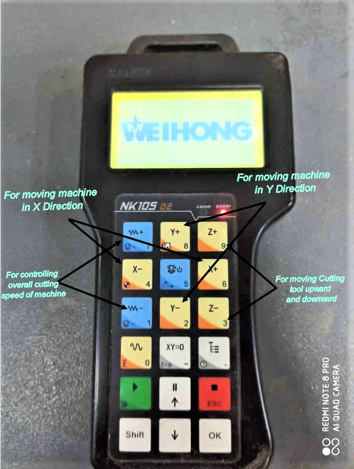
* This is the controller of the machine
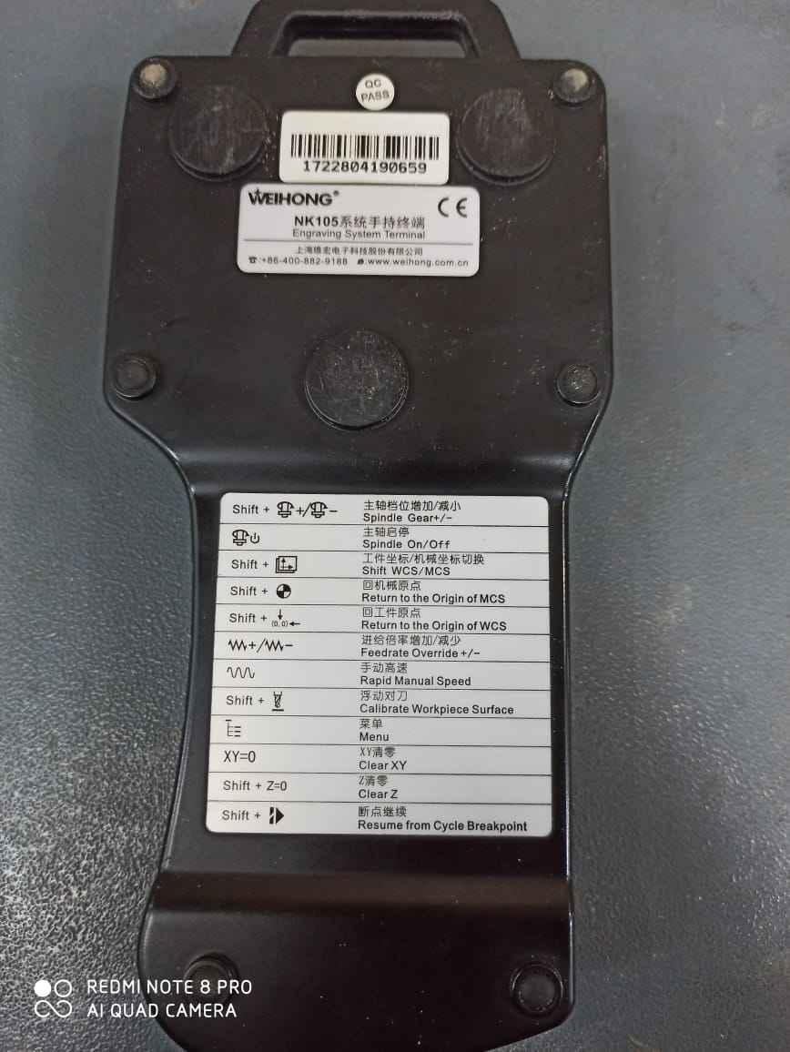
* These are some basic commands for operatring the controller
Group Assignment
Before we can start working we need to characterize the working of machine
Test 1
In this test we run our machine at several different configuration by varrying cutting speed and spindle rpm , trying to get the best configuration for comparativel best result
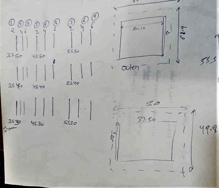
Before we can start we have written all the things which we want to do on a piece of paper
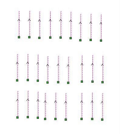
Prepared these simple lines of 8cm on the aspire int hte batch of 3 and for every configuration of 3 the depth of cut increase by 2 cm every turn
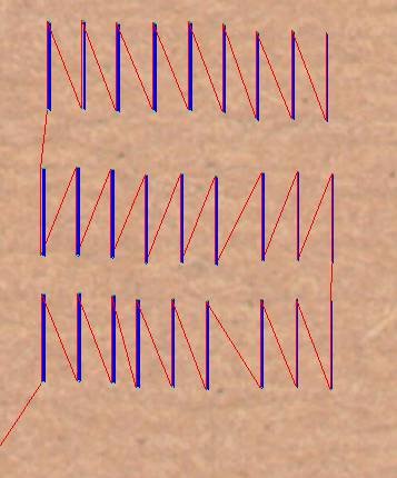
Then create a simple tool path giving machine vector as ON
And started cutting
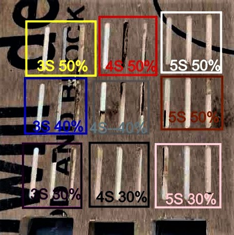
These are all the parrameter
yellow--3S 50%
Red--4S 50%
White--5S 50%
Blue--3S 40%
Grey--4S--40%
Brown--5S 50%
Purple--3S 30%
Black--4S 30%
pink--5S 30%
The cutting speed is mentioned in % on the teach pendant from 10% to 100%. The instructor suggested not to go beyond 50% for safety reasons.
The spindle speed is denoted by a number followed by S with 4S being the slowest and 7S being the fastest. The maximum spindle speed at 100% is 24000 rpm and every S is almost 3000 rpm.
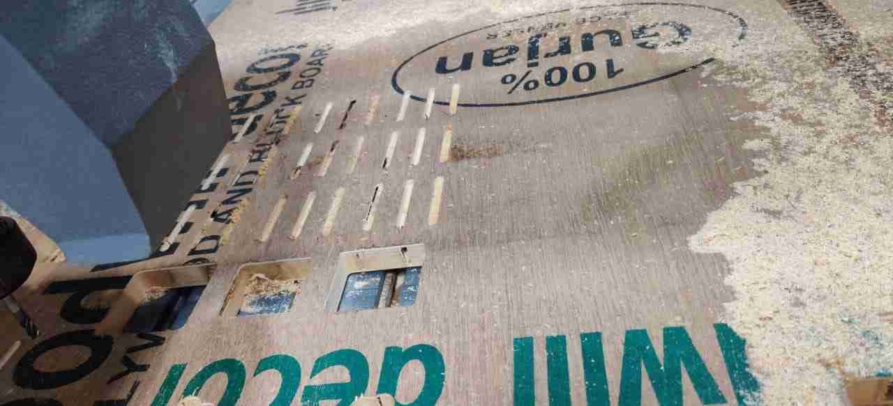
Conclusing
The best result was obtained from 3s and 30% speed
Test 2
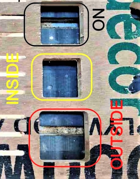
Purpose of this test was to determine the accuracy of the machine as well as how it purforms when we try all 3 vectors i.e "Outside" , "inside" and "On"
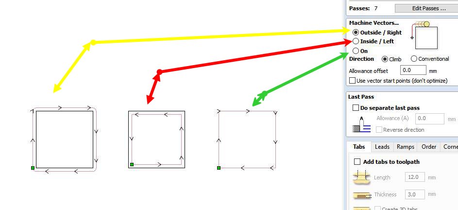
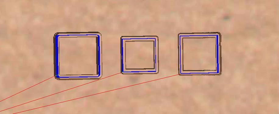
For that we draw sqaure of 50mm and tried all the configurations on it
Created the tool path for that a well
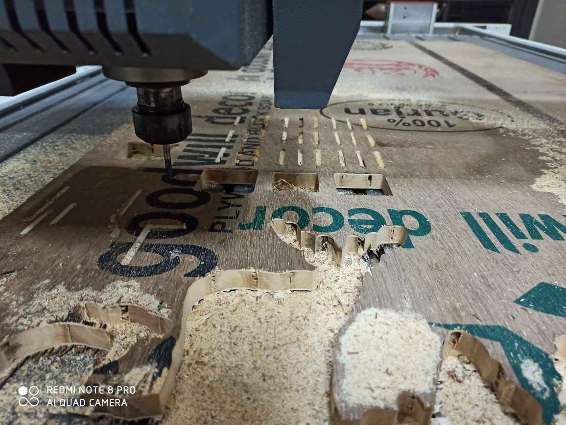
Machine working
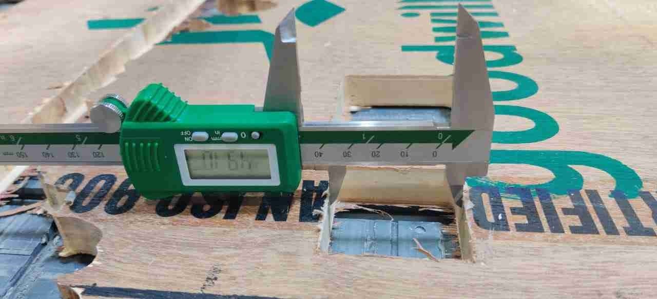
And results of the test are as follow
1. In the case of INSIDE vector we got perfect 50 X 50mm and got the inner cutout of 37.4 X 37.5mm
2. In the case of OUTSIDE vector we got a rectangle of 62 X 62mm and got the inner cutout of 50 X 50mm
3. In the case of ON vector we got 55.5 X 56 mm and got the inner cutout of 46 X 46mm
Individual Assignment
For this week it was required for me to make something big , by designing and cutting that on wood router
Bladeless FAN
An air multiplier, sometimes called bladeless fan, is a fan which blows air from a ring with no external blades. Its vanes are hidden in its base and direct the collected airflow through a hollow tube or toroid, blowing a thin high-velocity smooth airflow from holes or a continuous slot across the surface of the tube or toroid. The first concept was created by Toshiba in 1981.
By going through this video i decide to try to make this thing and in start though this will be something good to make but as i start working i was not that much sure , let me explain why
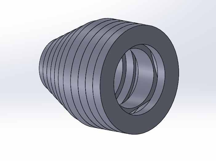
After testing i came up with this design
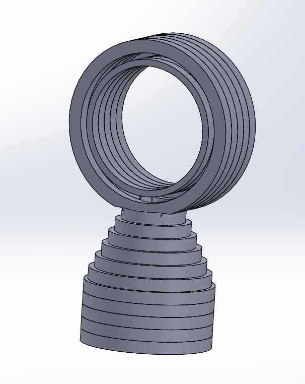
This is the final CAD design
As i explained , i will stack these piece one over other
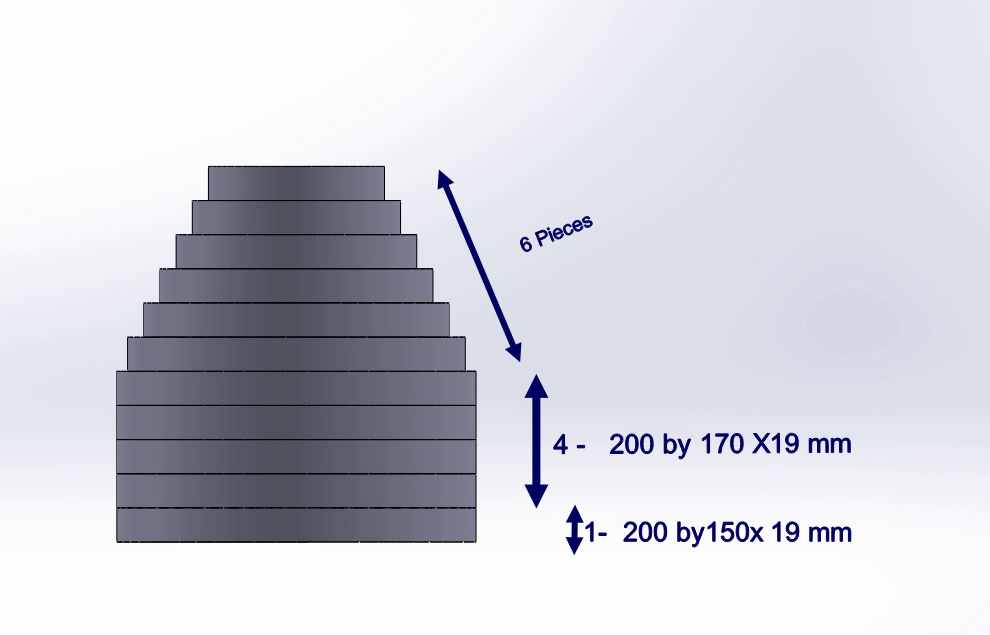
Something like it should look , i will explain the design from botoom to up
* Bottom on has 200mm external diameter and 150 mm internal diameter circle , so i can mount the fan on it
* Then the upper 4having same dimention of External 200 mm diameter and internal of 170 mm diameter
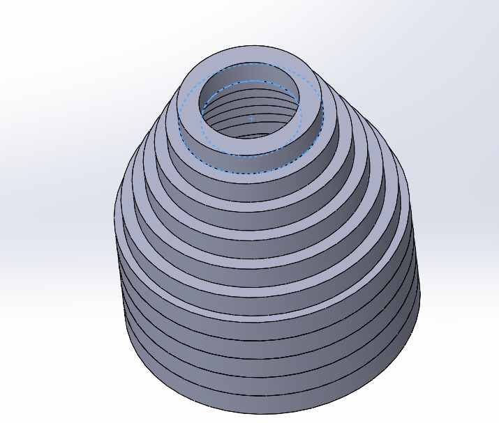
* then on the top of that there will be 6 pieces on it having consecutively 20mm size reduction
It should look something like this from bottom side
Laser cutting trial
In the start like every one else , i started cutting cardboard pieces on laser for testing bedore i can work on the wood router to valid my design ,by reducing the size of what i would like to make and see how good
it will look
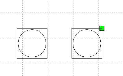
i designed a sqaure of 70 mm having a 65 mm circle inscribe in it as it was the same size fan which i want to fit in it initially
Then designed 100mm diameter cicle to add that square inside it
I am attaching AUTOCAD 2020 downloadable files
Bladeless fan DXF and DWG file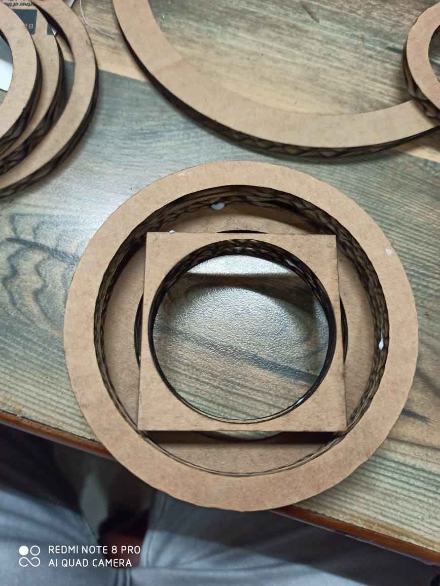
Then started cutting them and stacking one on each other , in the same way as we used to with building clock when we were kids
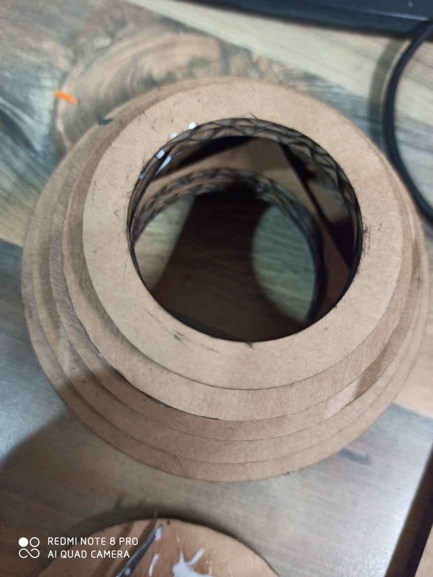
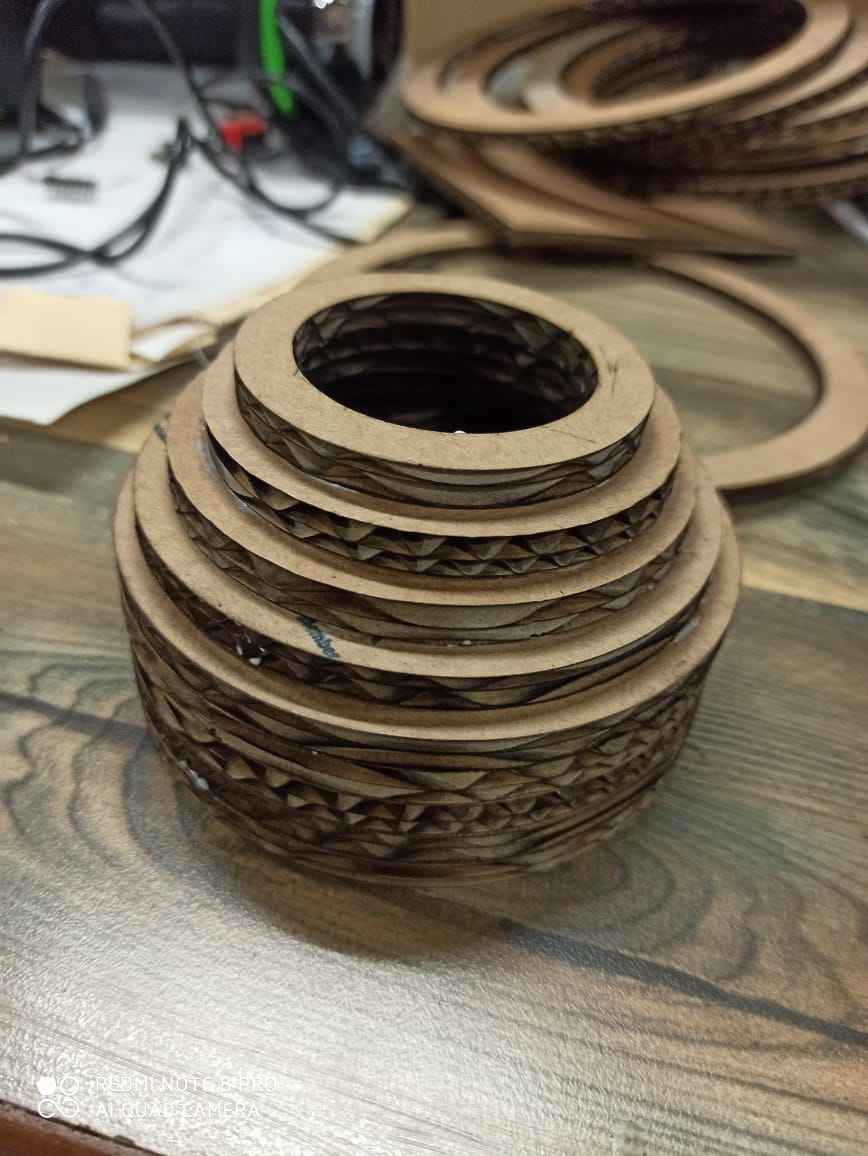
When i though i got enough height and the opening on the top is suffecient
Then i made the circles for top having diameter of 120 mm
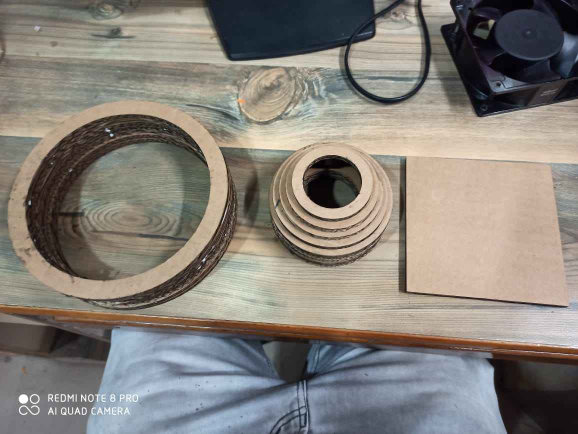
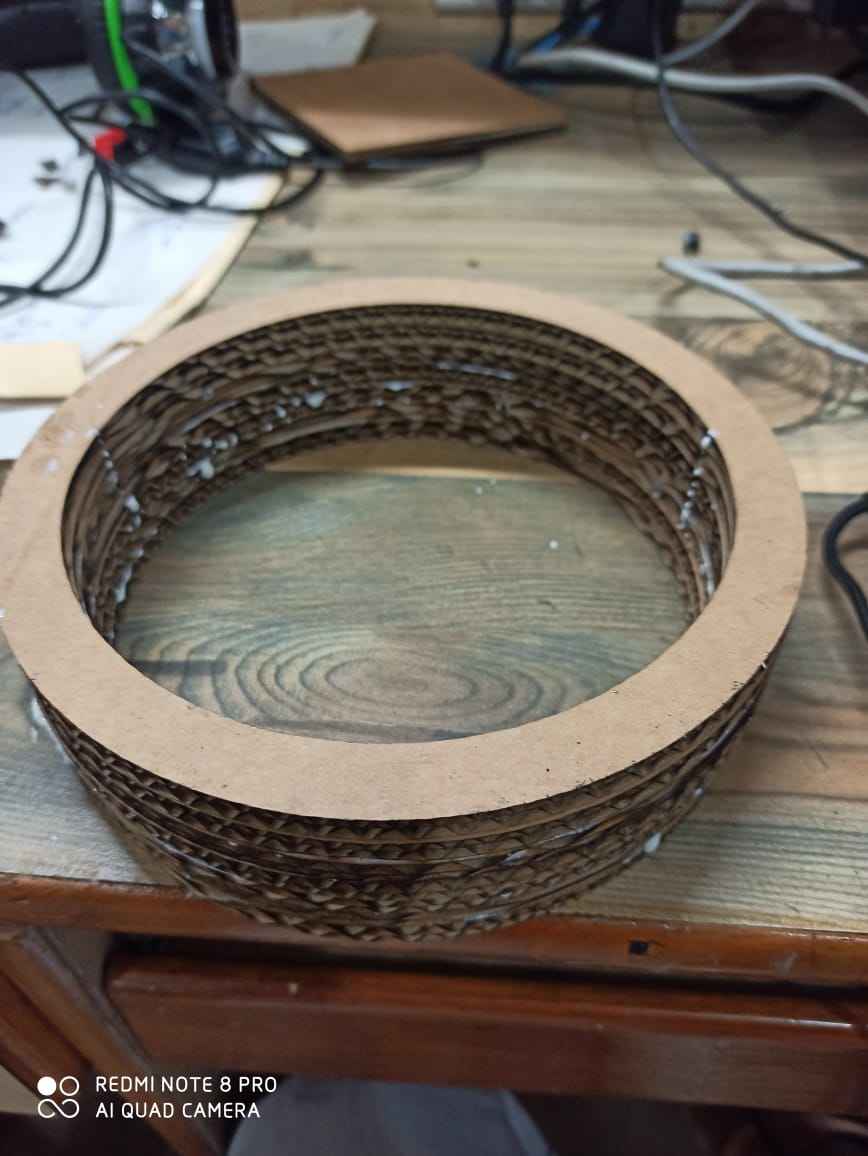
Its time to assemble it , i used fevicol for this purpose
Right know it looks awesome and anyone like me would love to make it on would
Cutting on CNC wood Router
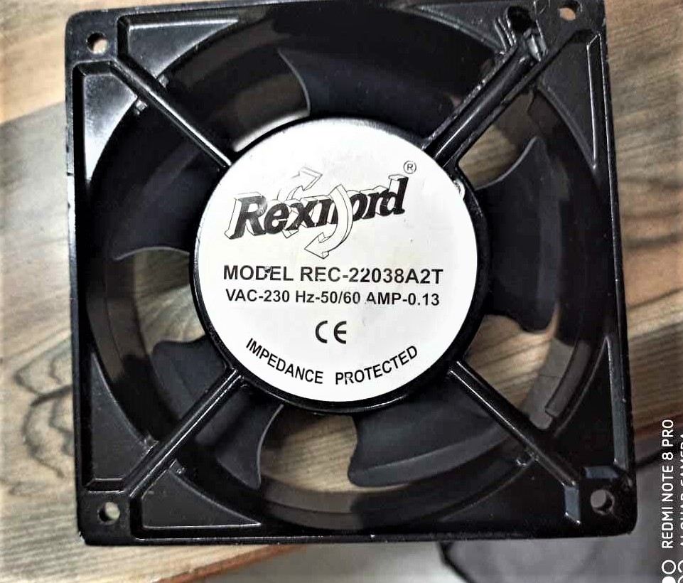
This is a AC 120 mm brushless fan , i have started working with this fan due to its high CFM
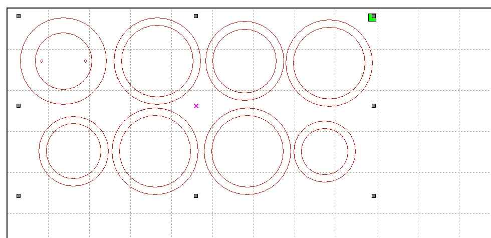
I made the rings in aspire as well , plus to sae the material which is not going to be used it also added a hexagonal shape to it so i can use it in fuure
As you can see i provided different vector for different geometry
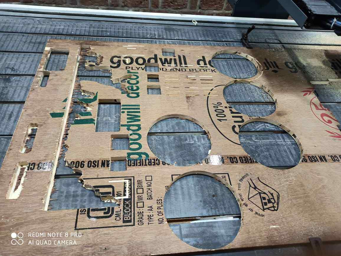
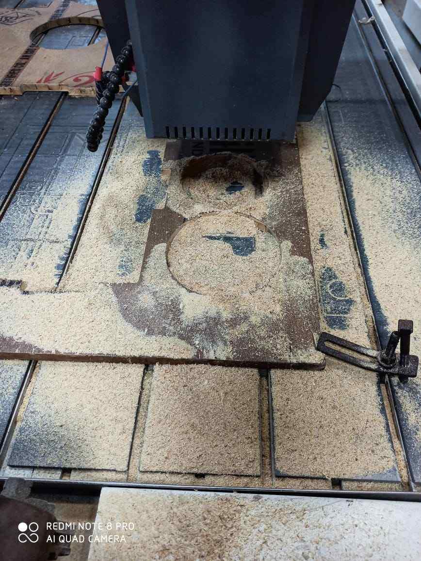
Then i started cutting of pieces , as we have shortage of the material at this point i dont have choice i need to cut the rings whereever i ot the space
From the test 1 got this that the best parameter will be 3s spindle speed and 30% cutting speed , so i also use the same setting
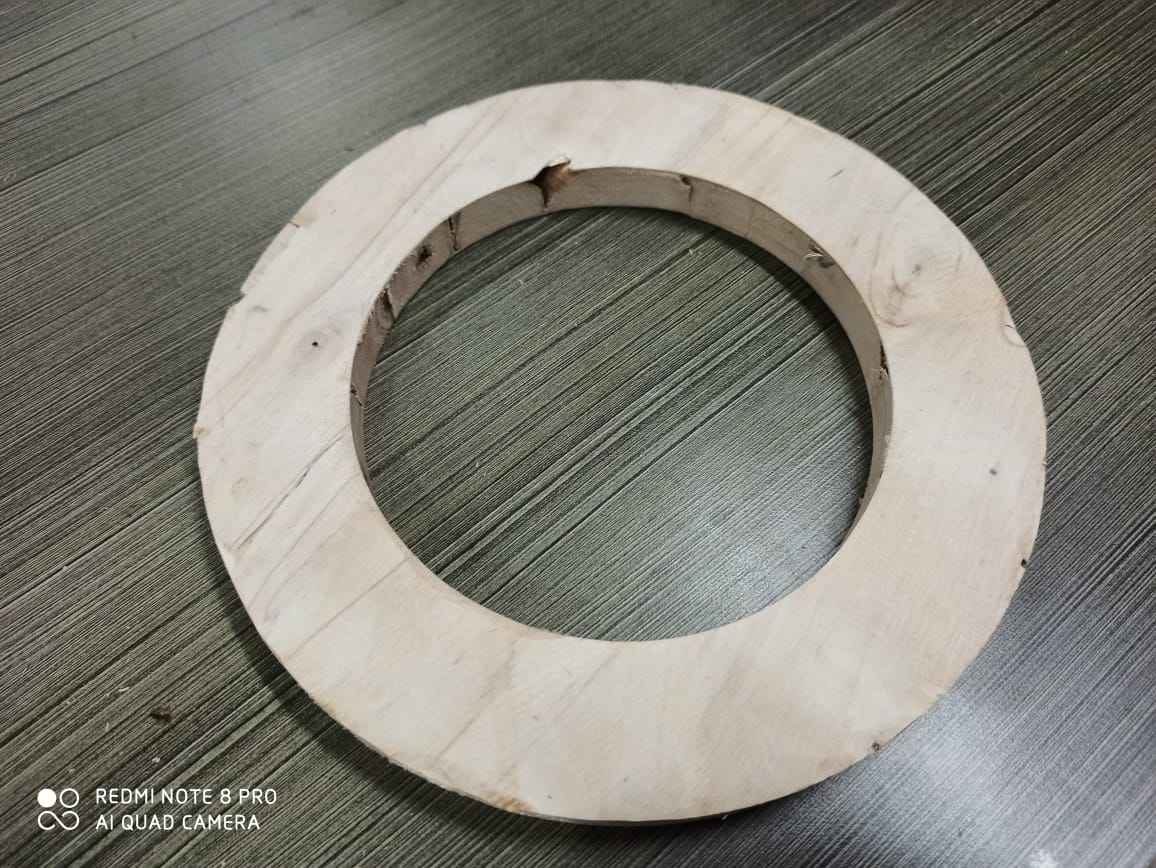
First thing which i cut was the bottom ring
followed by 3 rings were made and test the fiting
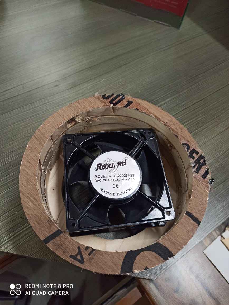
As you can see that the fan fits easily
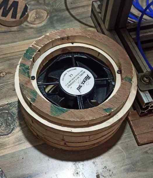
I added 2 more ayer to check the whole fitting
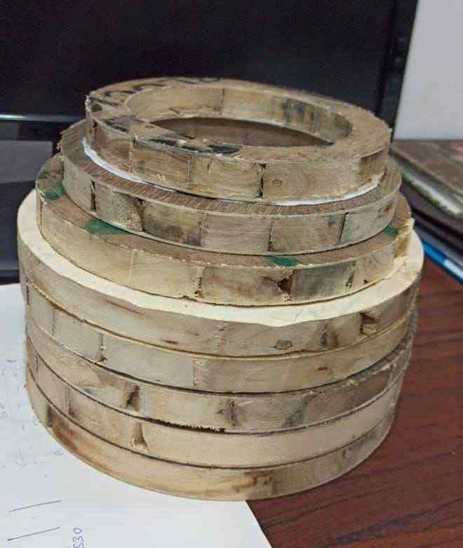
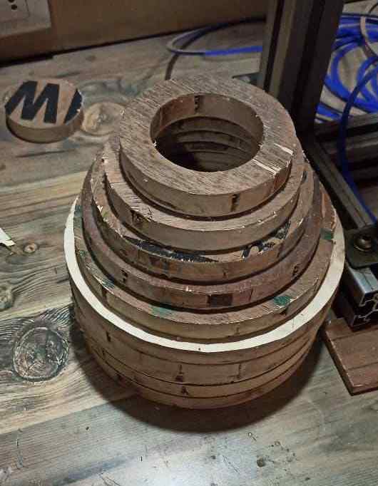
And from that point i started decreasing the size of opening by making small rings to fit on the other rings

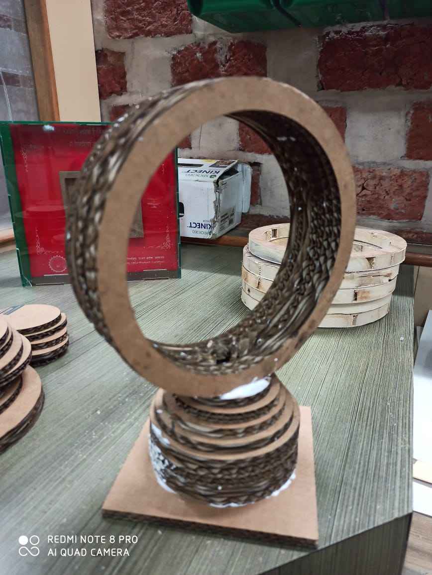
Then made this upper circle as i explained in the image
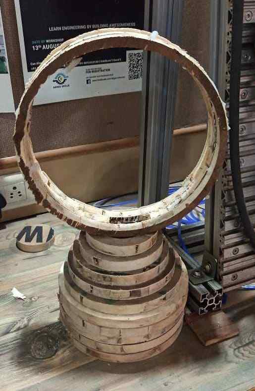
I attached this circle on the top of the opening so air can pass throgh it
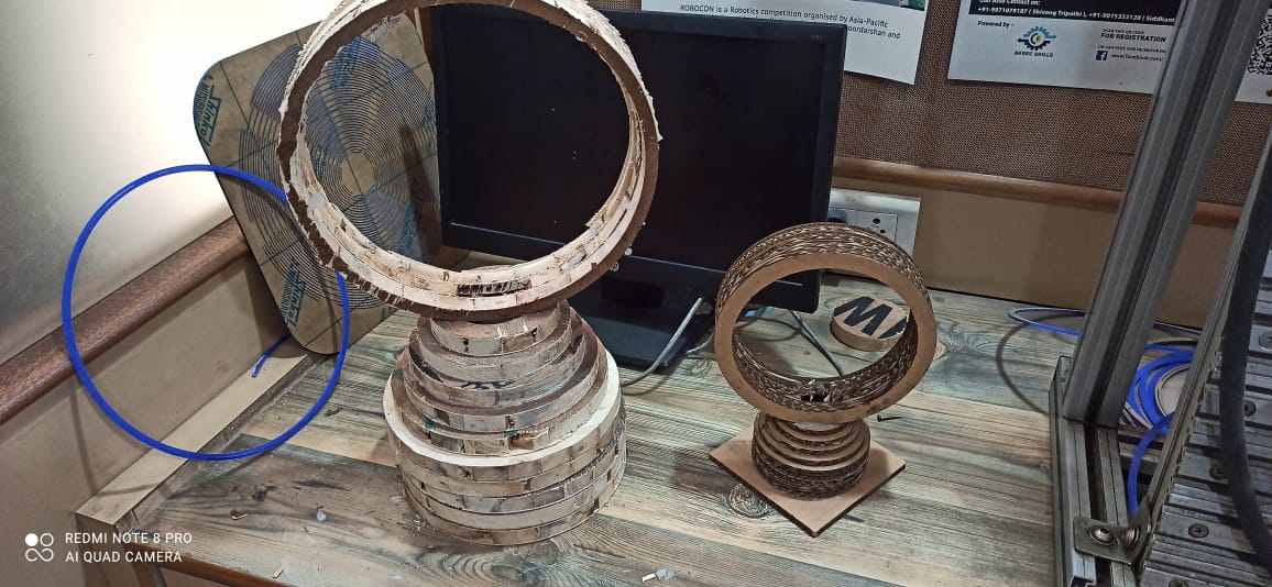
This will be my hero shot
And if you want to download the CAD editable file you can click on this link for that
Bladless fanThis week didnt go as planned as
1. Initially i didnt take in consideration that how much material is going to waste for my something big and it was too much
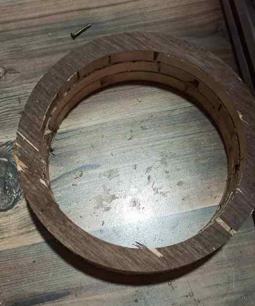
2. The wood at the lab was so soft manytimes the wood broke when we try to remove it from full sheet , it didnt have any strength
3. Due to covid we didnt have enough supply and as neeraj sir required to make his final project on the wood , we all required to do sacrifice