Computer-controlled cutting (WEEK 4)
Group assignment:
Characterize your lasercutter 's focus, power, speed, rate, kerf, and joint clearance
individual assignment:
- Design and Cut something on the vinylcutter design
- Design and lasercut, and document a parametric construction kit,accounting for the laser cutter kerf, which can be assembled in multiple ways,and for extra credit include elements that aren't flat
IMPORTANT NOTE : ALL OF MY IMAGES ARE POP UP IMAGES , IF YOU HAVE ANY PROBLEM READINGS THOSE IMAGES , PLEASE CLICK ON THEM AND THEY WILL ENLARGE AUTOMATICALLY AND YOU CAN READ THEM EASILY
Machines used
1. Graphtec-CE-6000 (vinyl cutter)
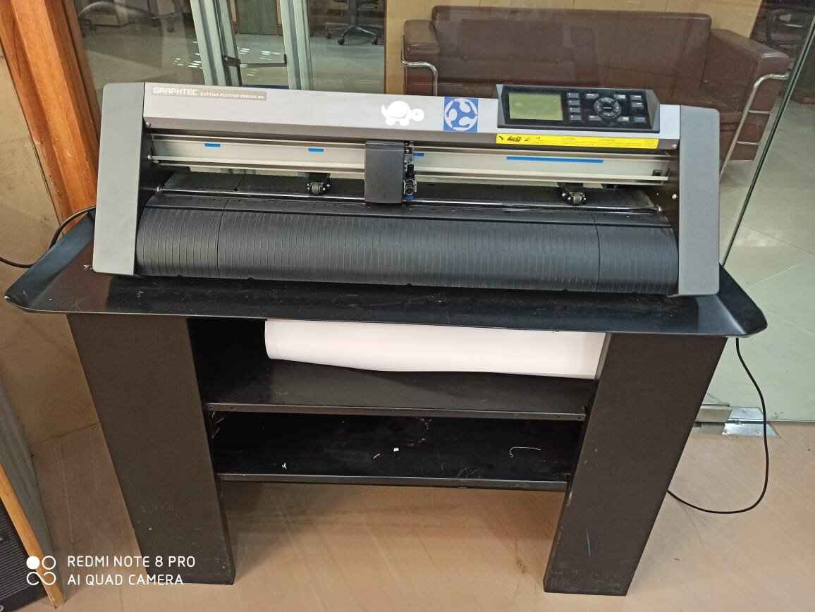
A vinyl cutter is a type of computer-controlled machine. Small vinyl cutters look like a desktop printer. Like a printer controls a nozzle, the computer controls the movement of a sharp blade over the surface of
the material. This blade is used to cut out shapes and letters from sheets of thin self-adhesive plastic (vinyl).
The vinyl can then be stuck to a variety of surfaces depending on the adhesive and type of material. The one major limitation with vinyl cutters is that they can only cut shapes from solid colours of vinyl.
A design with multiple colours must have each colour cut separately and then layered on top of each other as it is applied to the substrate.
Also, since the shapes are cut out of solid colours, photographs and gradients cannot be reproduced with a stand alone cutter. In our fab lab, we use Roland Camm-1 vinyl cutter.
Software used
Gaphtec studio
Through this link You can Download the Original software according to specifications/ model of your machine
Getting started with software
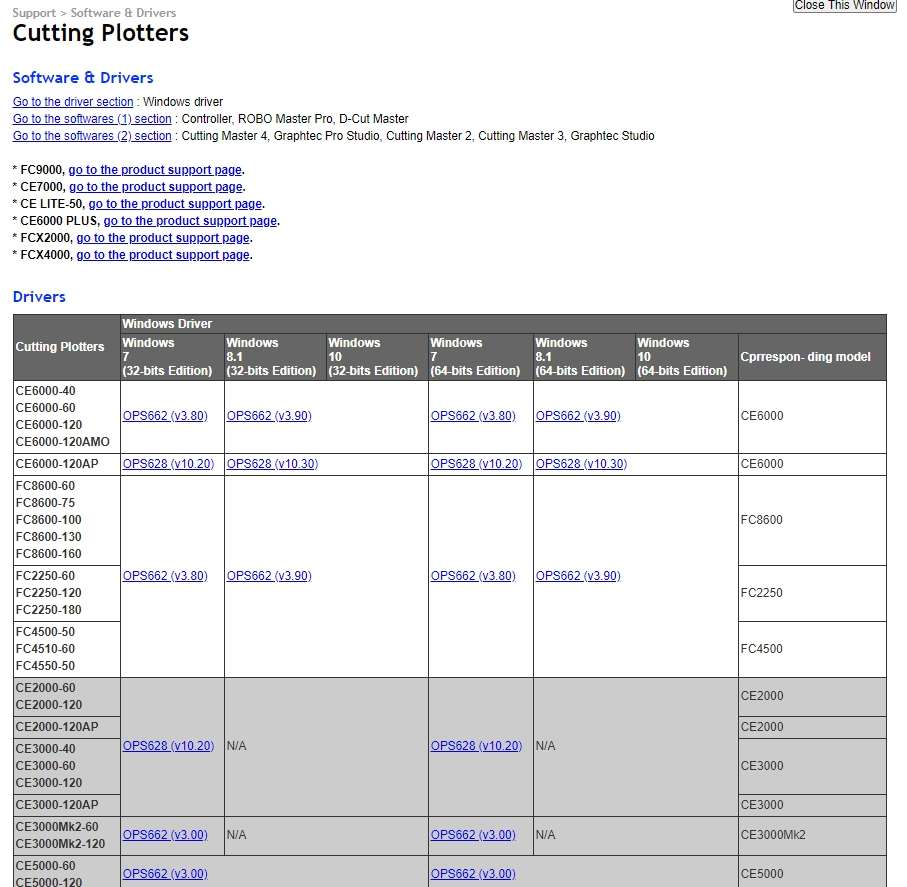
* Through the link i have given above, first download the software
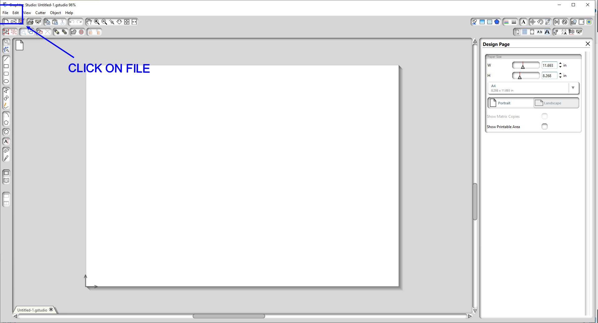
* First click on the top left conner on the File menu
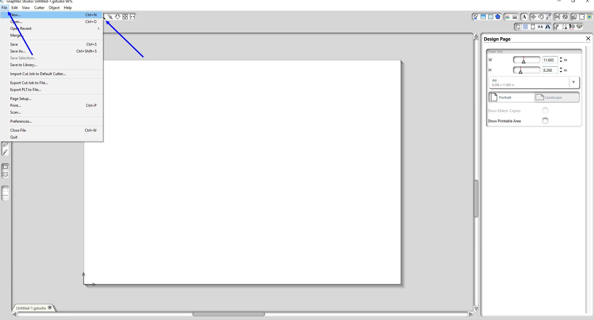
* Then click on the NEW to select a new page.
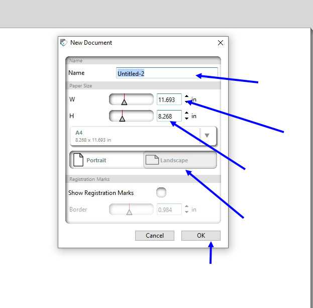
* Give name to the file * Select the width and height of the page * Then choose which type of page your required :- Landscape / Portrait
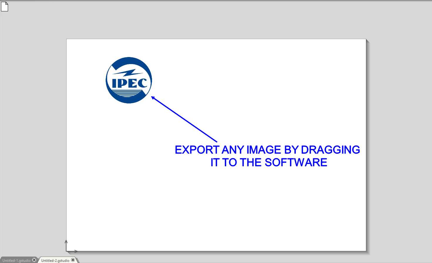
* To start sketching import or drag any png or jpg image to the graphtec studio.
For cutting any thing in vinyl cutter we require that we have have outline of the image so we require to trace it
* STEPS FOR TRACING
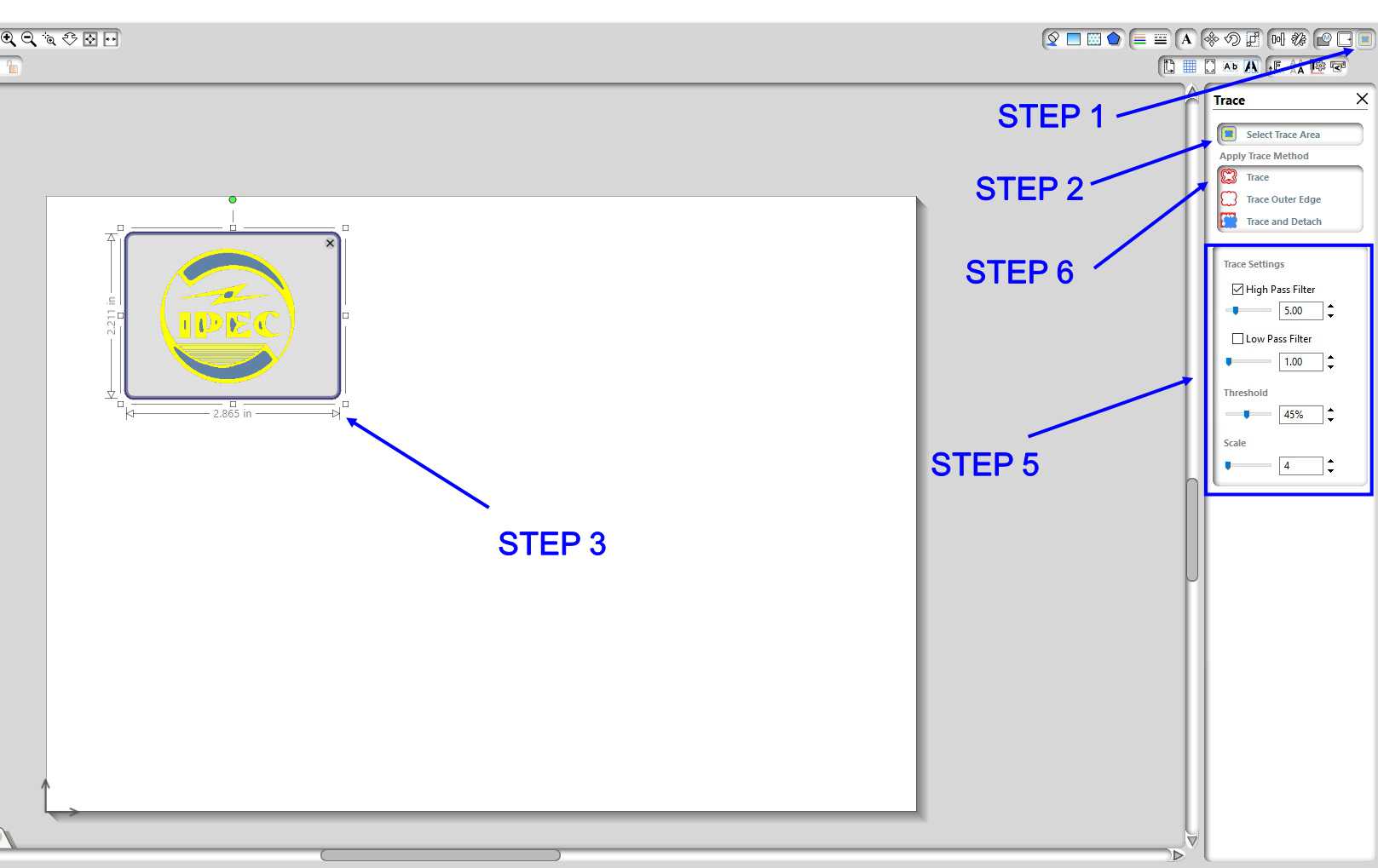
Step 1: Click on the top right connor option on the trace button.
Step 2: Then click the 'SELECT TRACE AREA' command.
Step 3: Select the area which required to be traced.
Step 4: For getting perfect trace you need to play with trace setting to get the optimum trace parameter.
Step 5: Then if its look like that you get a perfect parameter then click on 'TRACE'
* You will get a trace of image which you required for cutting
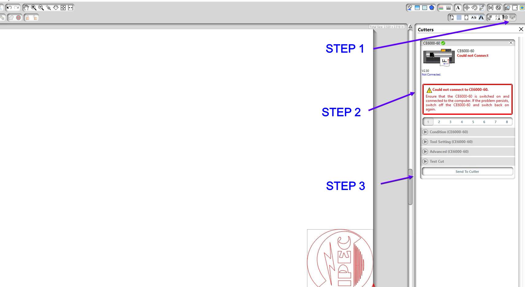
* STEPS FOR GIVING COMMAND TO MACHINE
Step 1: Click on the 'OPEN CUTTER WINDOW' option on the top right conner Then system will orient your cutting file according to space.
Step 2: Then POWER ON the smachine andd you will see the command and status ready.
Step 3: Then click on the 'SEND TO CUUTER' command.
And if you want to download the file you can do it by clicking int his link
ipec stickerGetting started with the machine
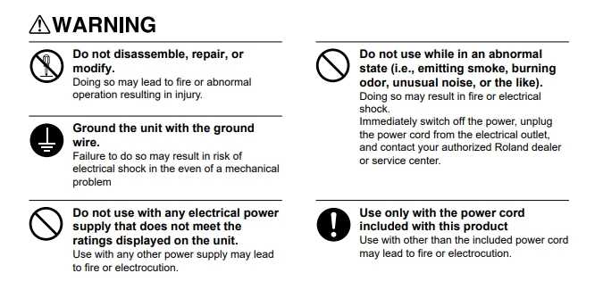
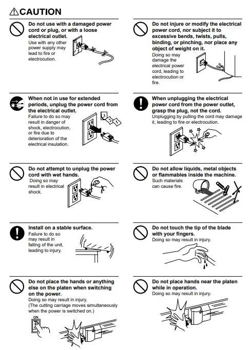
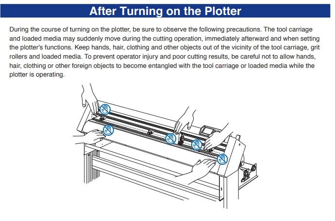
SAFETY RULES FOR VINYL CUTTER
* READ THESE INSTRUCTIONS BEFOR USING THE MACHINE
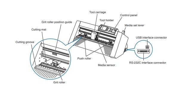
Lets get started
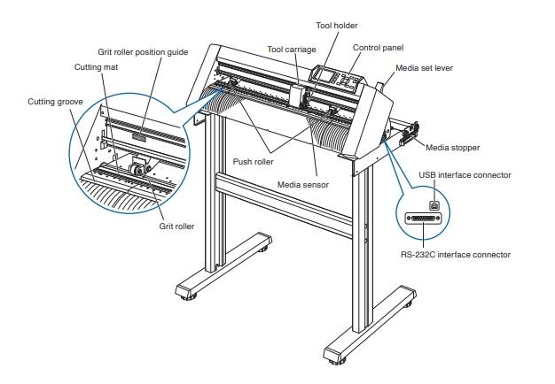
* This is the overall structure of the machine
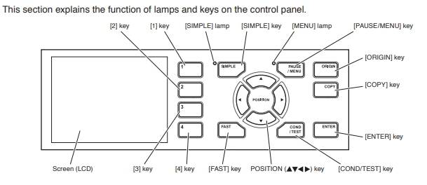
* This is the Command and control console of the machine
STEP 1
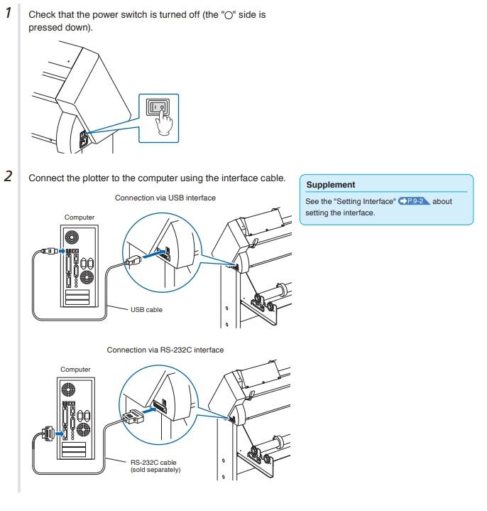
* Switch on the POWER of the machine
* Then connect the machine to your PC or personal laptop
STEP 2
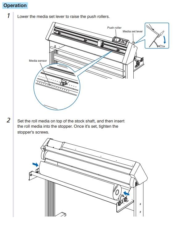
After switching ON the machine , the first thing we need todo is to add material for cutting
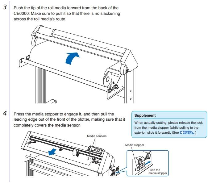
Through this image you can understand what you should do or what you shouldn't do during adding the material to machine
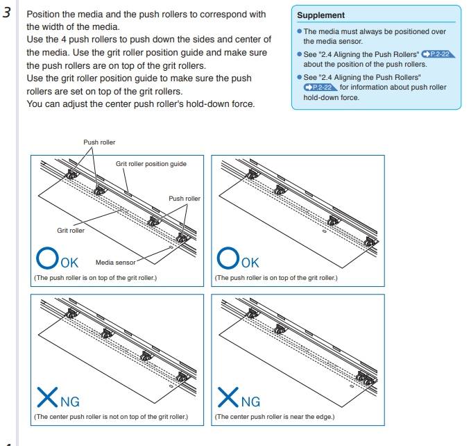
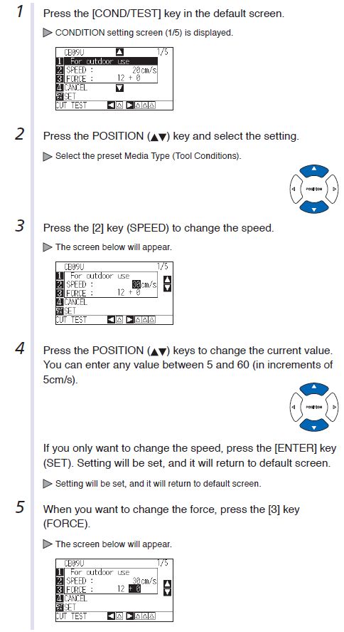
Setting the basic cutting Parameters
Setting the force value
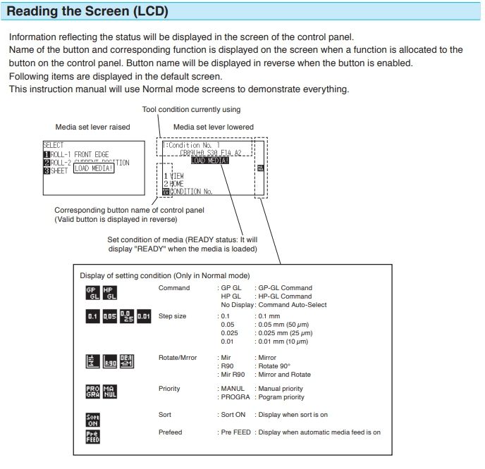
* Throught this image you can learn how to control the machine console
Setting the force value
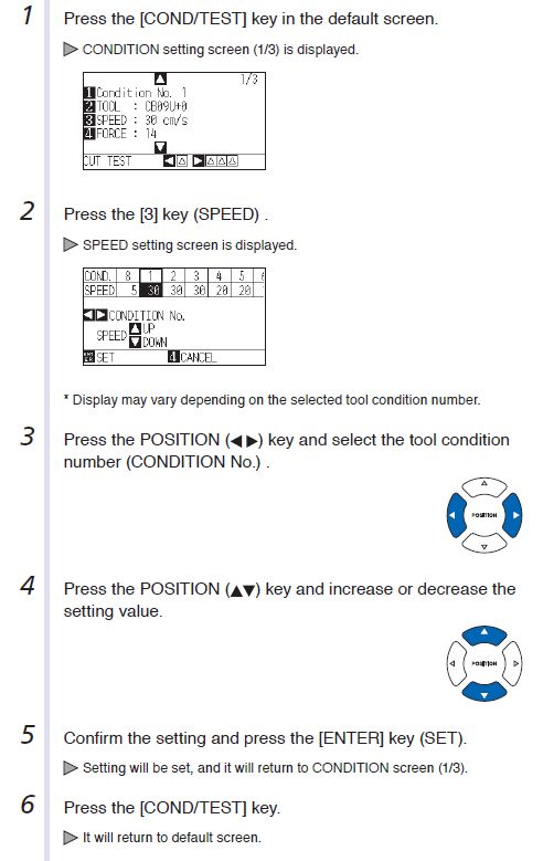
Setting the Speed
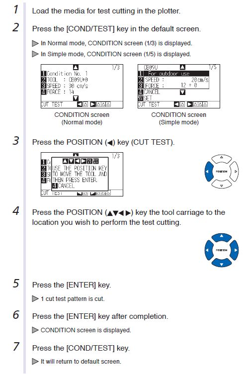
Test Cut
GETTING STARTED WITH STICKER MAKING
Before we get started , we require to collect these things which are very important for using vinyl cutter
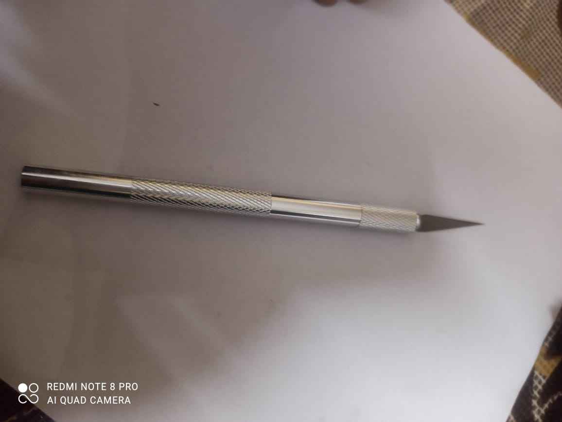
Sharp paper cutting knife
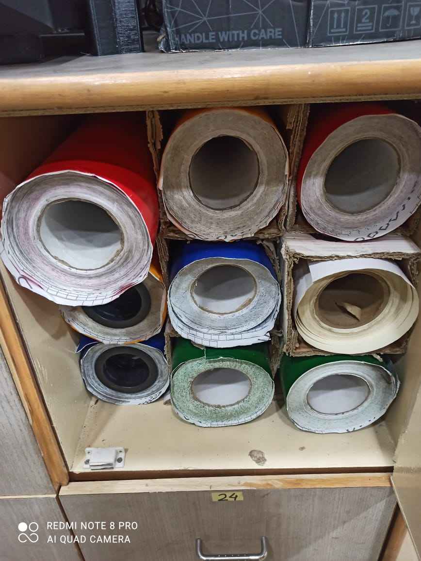
Vinyl paper role , at our lab we have 12in X 25ft and .5mm thick roles of vinyl paper
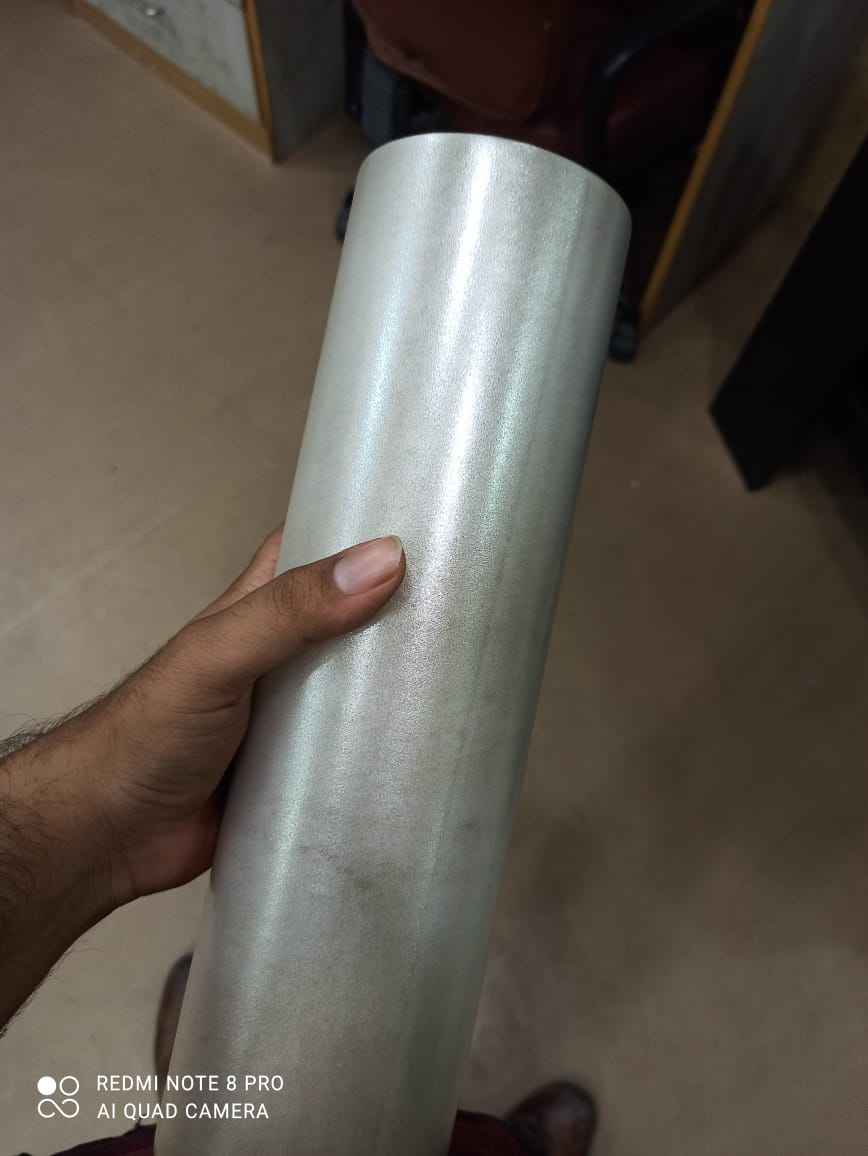
Transfer paper , so you can transfer your cutout/sticker from vinyl paper to any object
First cut out a small but sufficient amount f material from role , because you cannot use whole role its too heavy
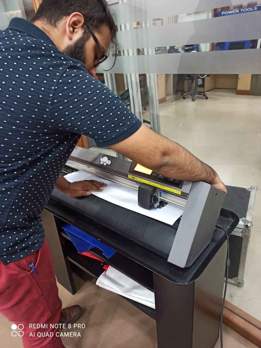
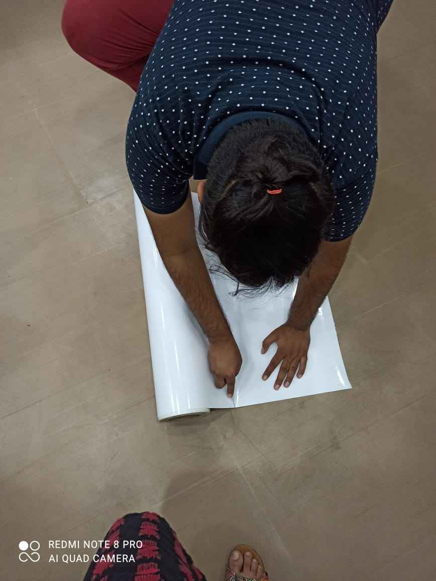
here I am inserting inyl paper in the machine (Doesn't i look handsome , what you think
Now we have initiated work now we can move towards cutting

This is a logo i made last week you can go and check that , i have also added a video explaining how i designed it.
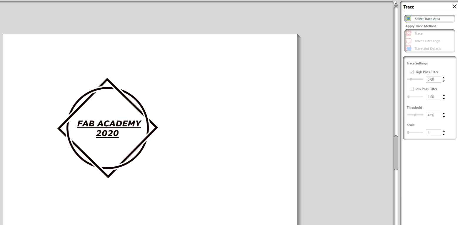
I added a PNG file to GRAPHTEC STUDIO

Then i traced the file and got these lines which i will use to cut
When i initially cut the sticker i saw that the blade rips off the sticker
at that cutting parameter's were
SPEED :6cm/s
FORCE :20
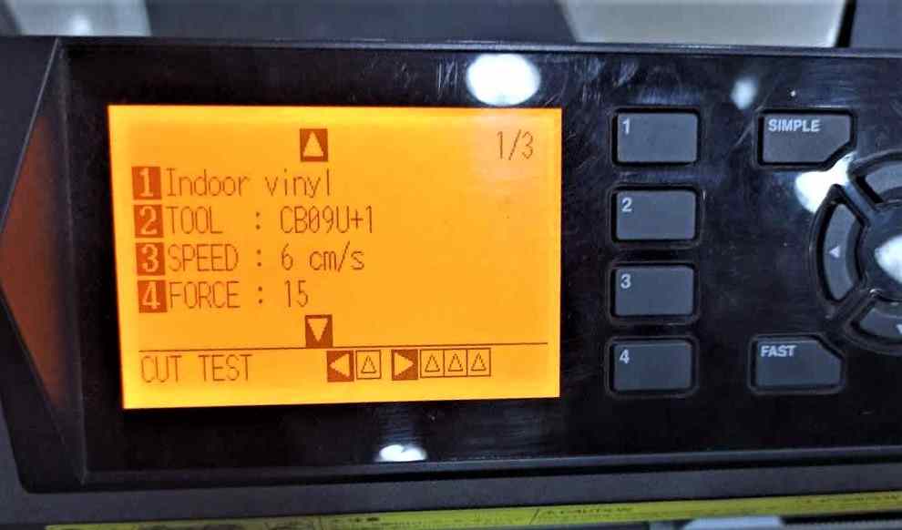
Then i reduced force to 15
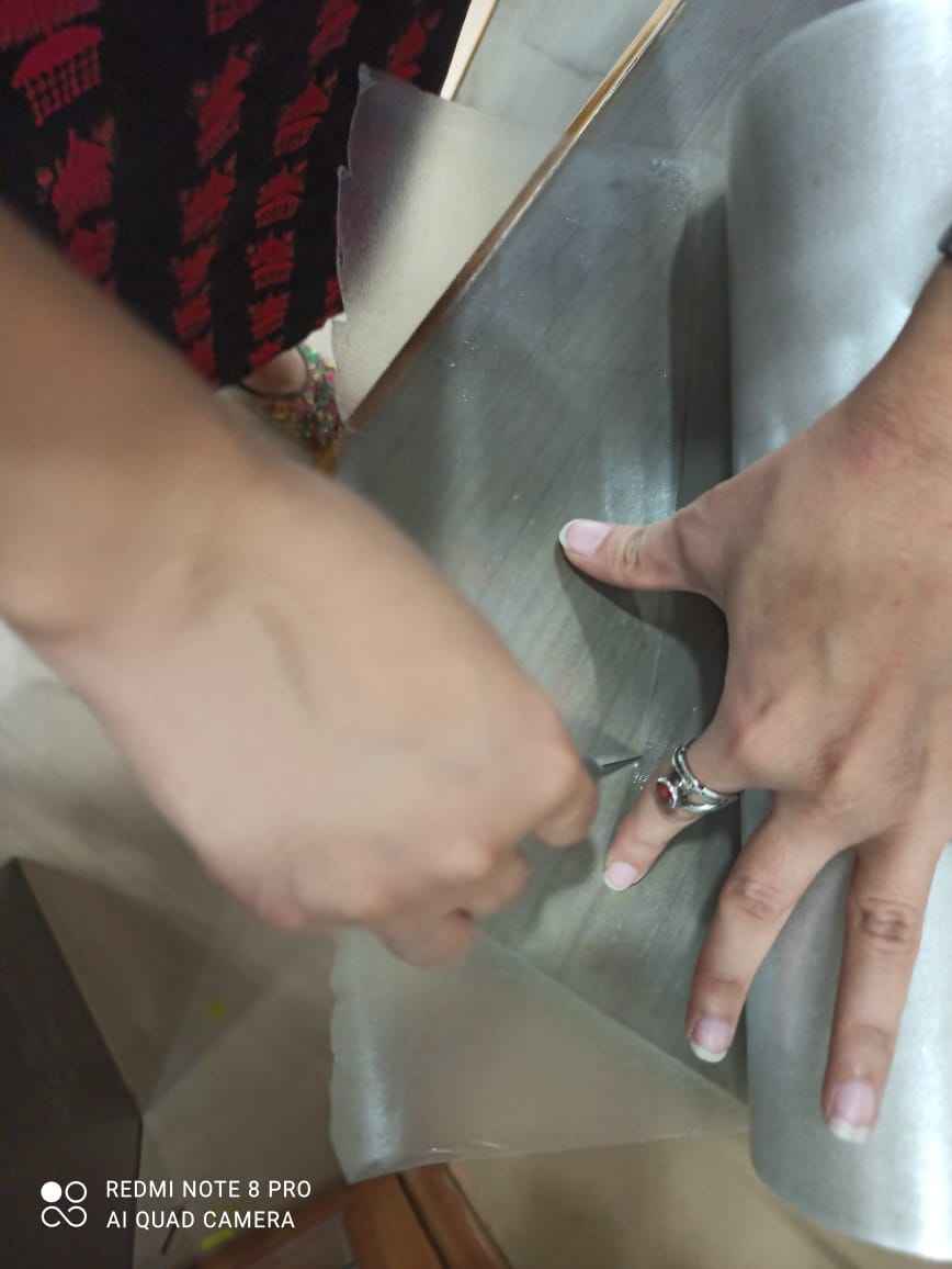
This time machine worked perfectly so i removed the vinyl sheet from machine after it cut the sticker and cut a small prortion of tranfer tape to apply it on the cutted sticker
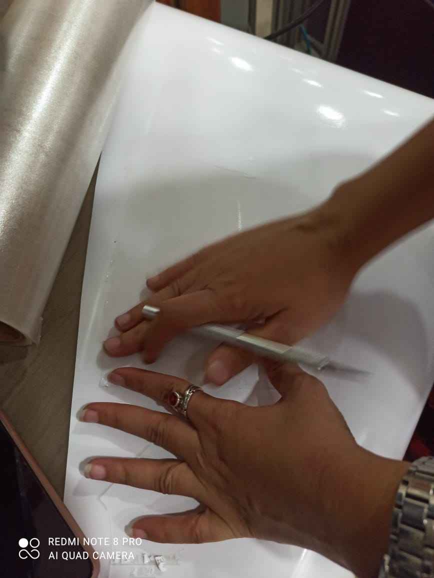
Then applied the transfer tape on the sticker and pressed it very hard , so the sutted sticker sticks properly
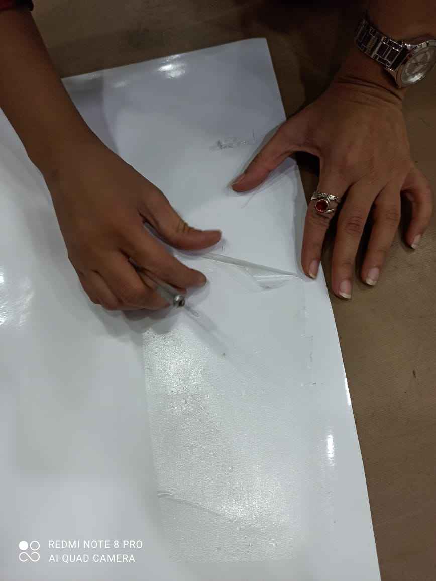
Now i stated removing the tape to get the sticker out of the sheet , this process is called weeding
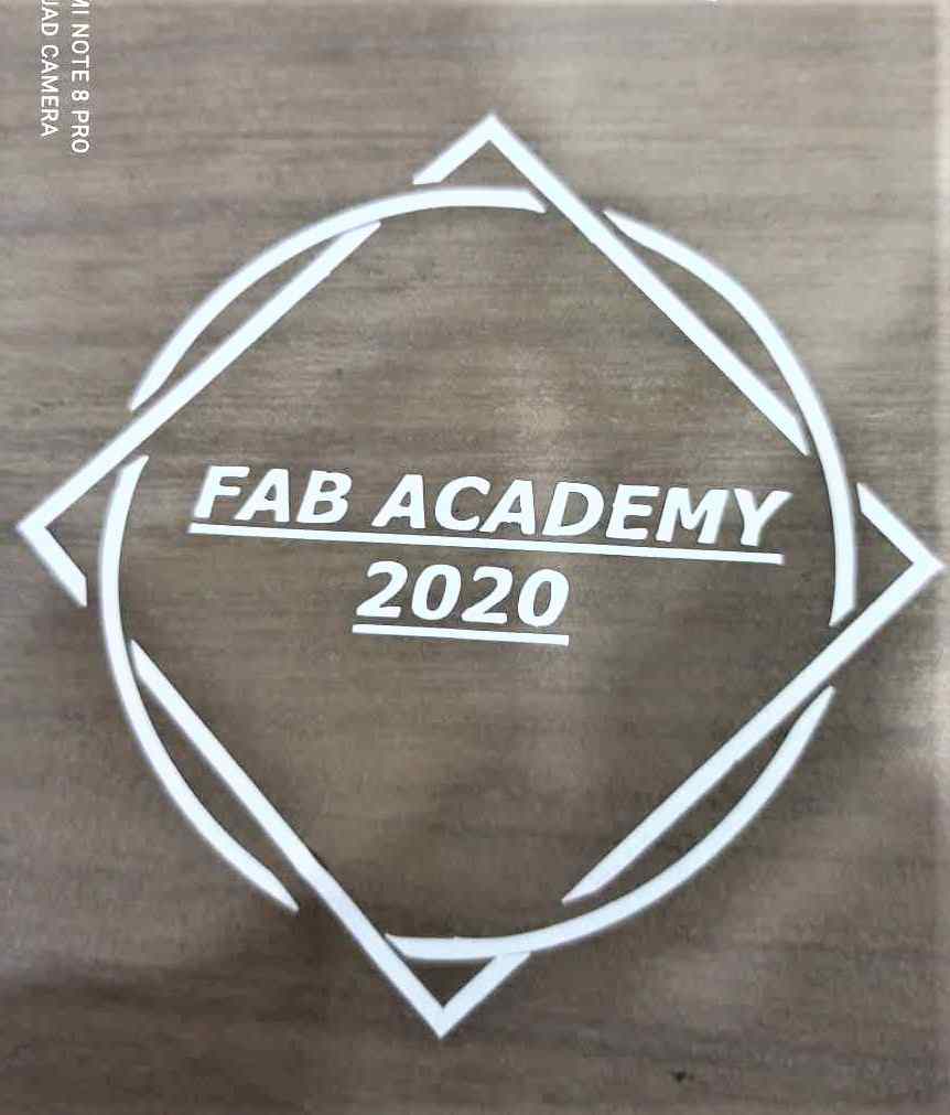
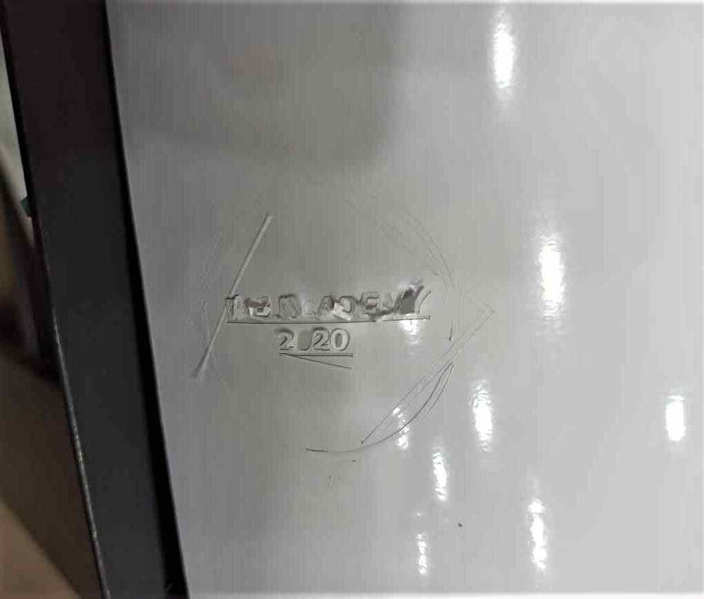
Then i appled the sticker on a table for testing , well honestly saying some parts are not cut properly so it was very difficult to get this sticker
This time i thought i should increase the force to 16 from 15 and this time i got awesome result
And if you want to download the file you can do it by clicking int his link
FAB Academy 2020MULTICOLOUR STICKER
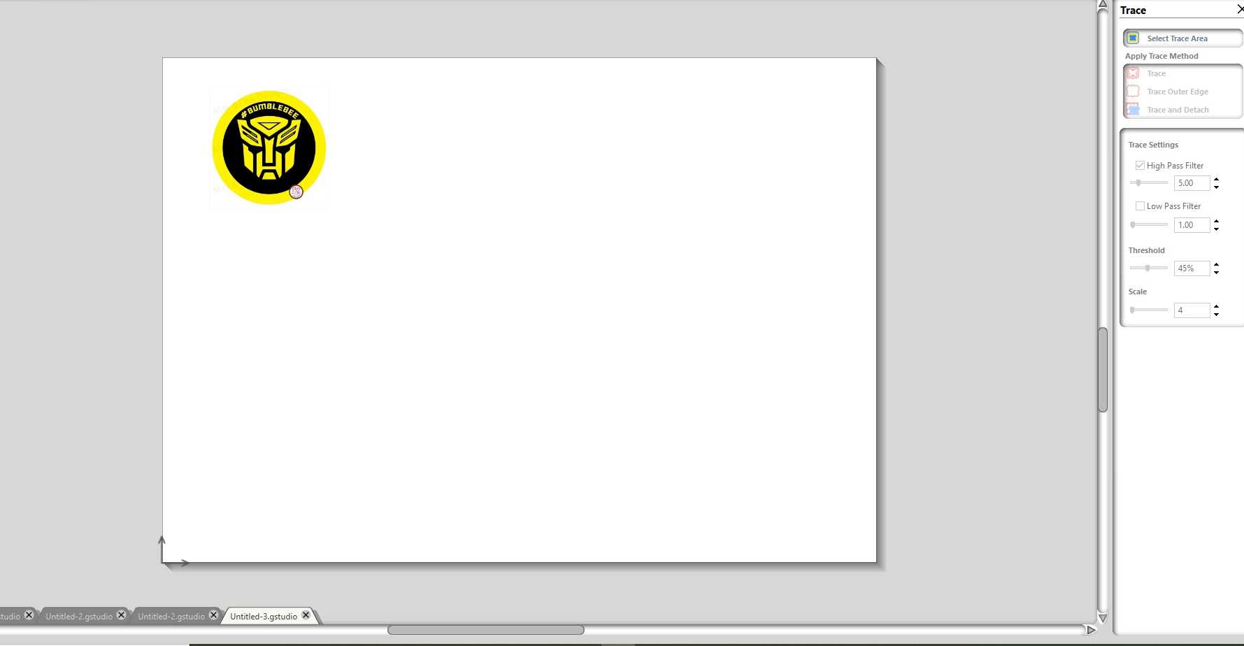
* Selected the image
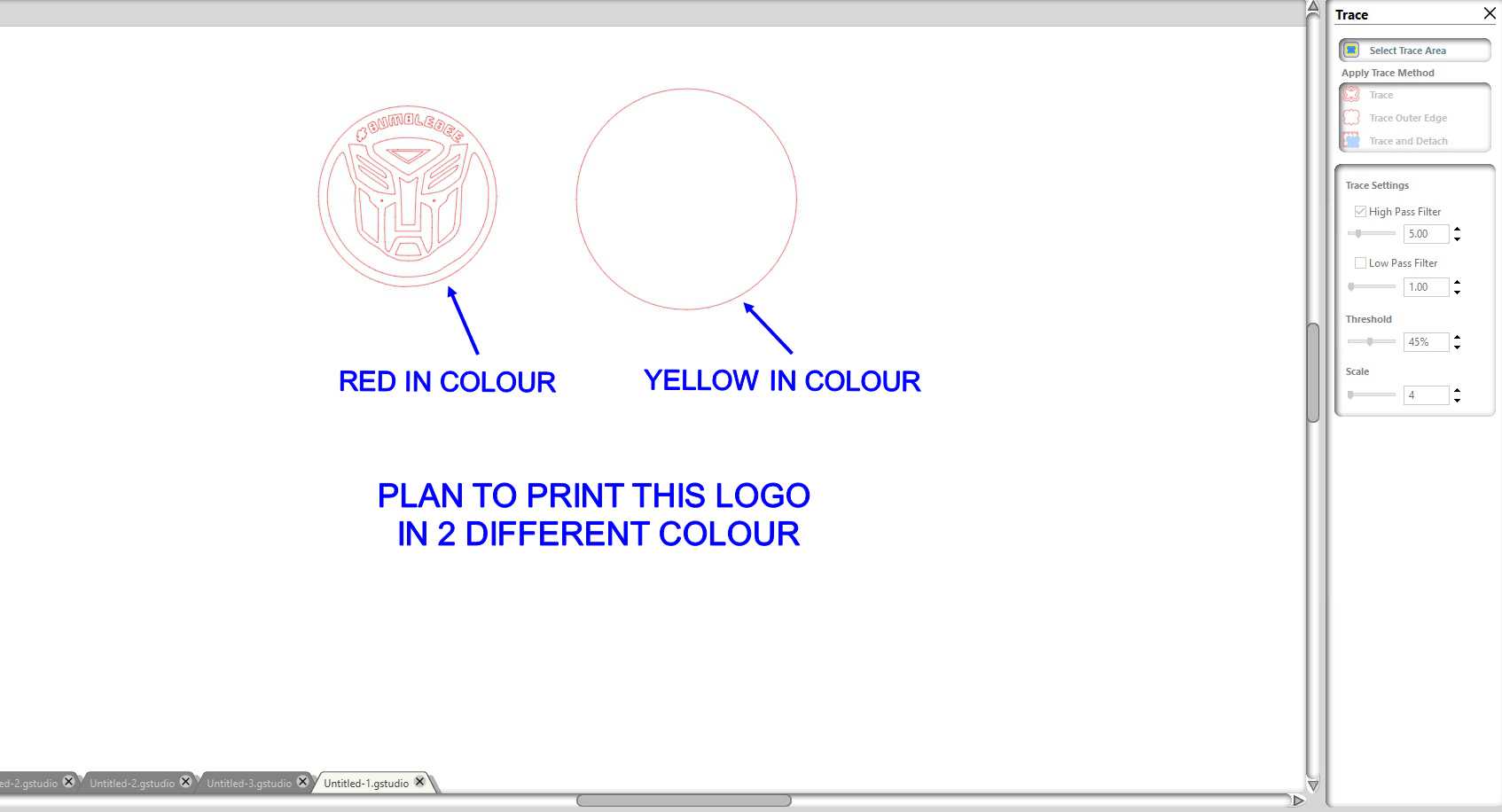
* Trace the selected the image and the process for this is same as the last one
And if you want to download the file you can do it by clicking int his link
Transformer sticker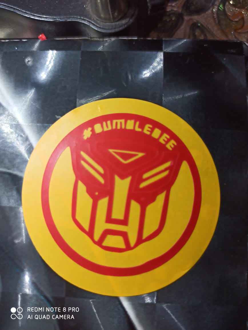
* Thats how it looks after the sticker is cutted
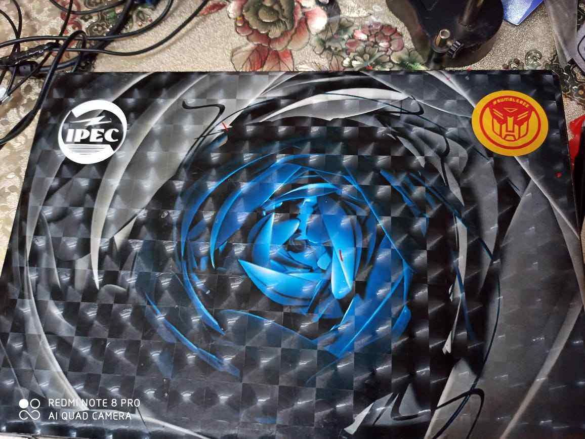
* Now you can place the sticker anywhere as you like and i prefer to docorate my laptop with these 2
Shot blasting and engraving
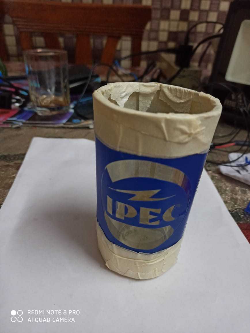
The ipec logo sticker which i cutted previosuly , i thought i should try to engrave it using shot blasting machine at some other lab so i paste the sticker on the glass
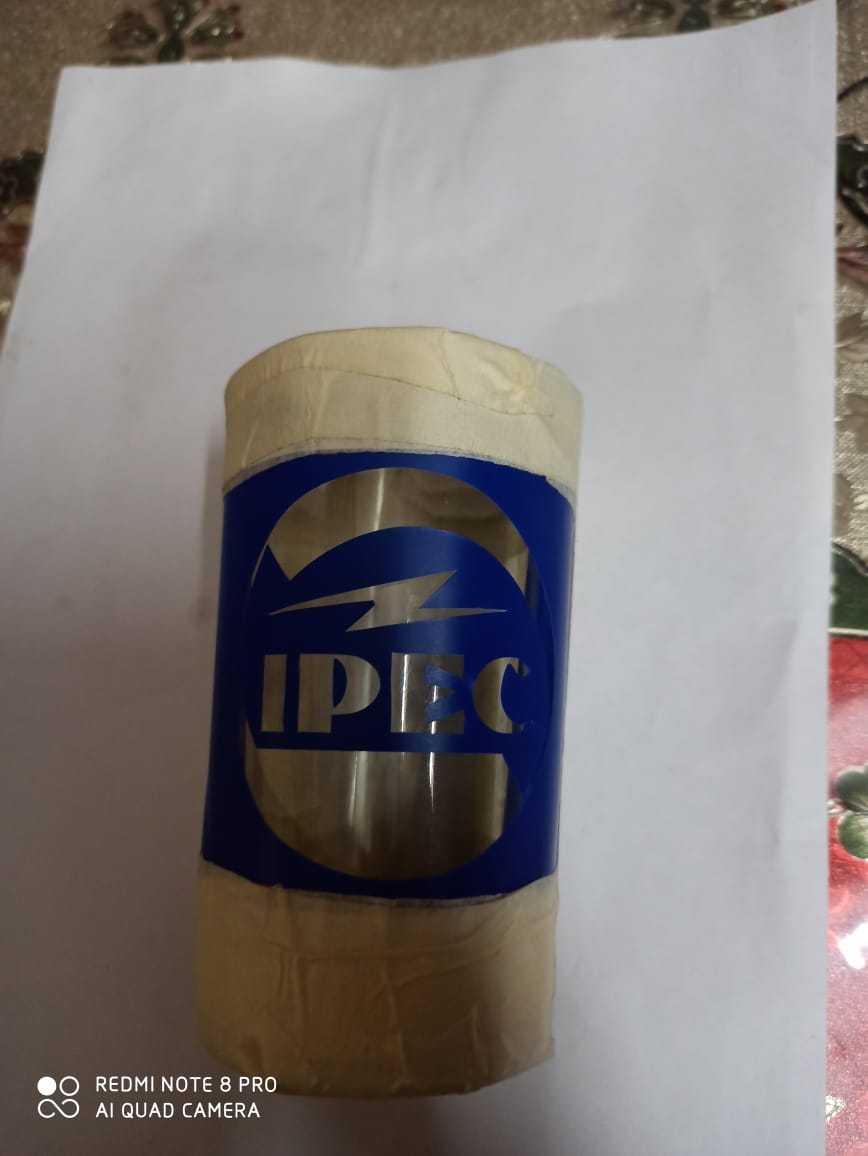
I also applied lots of masking tape /painter tape on it so only sticker part will engrave
2. SIL 100 watt Laser
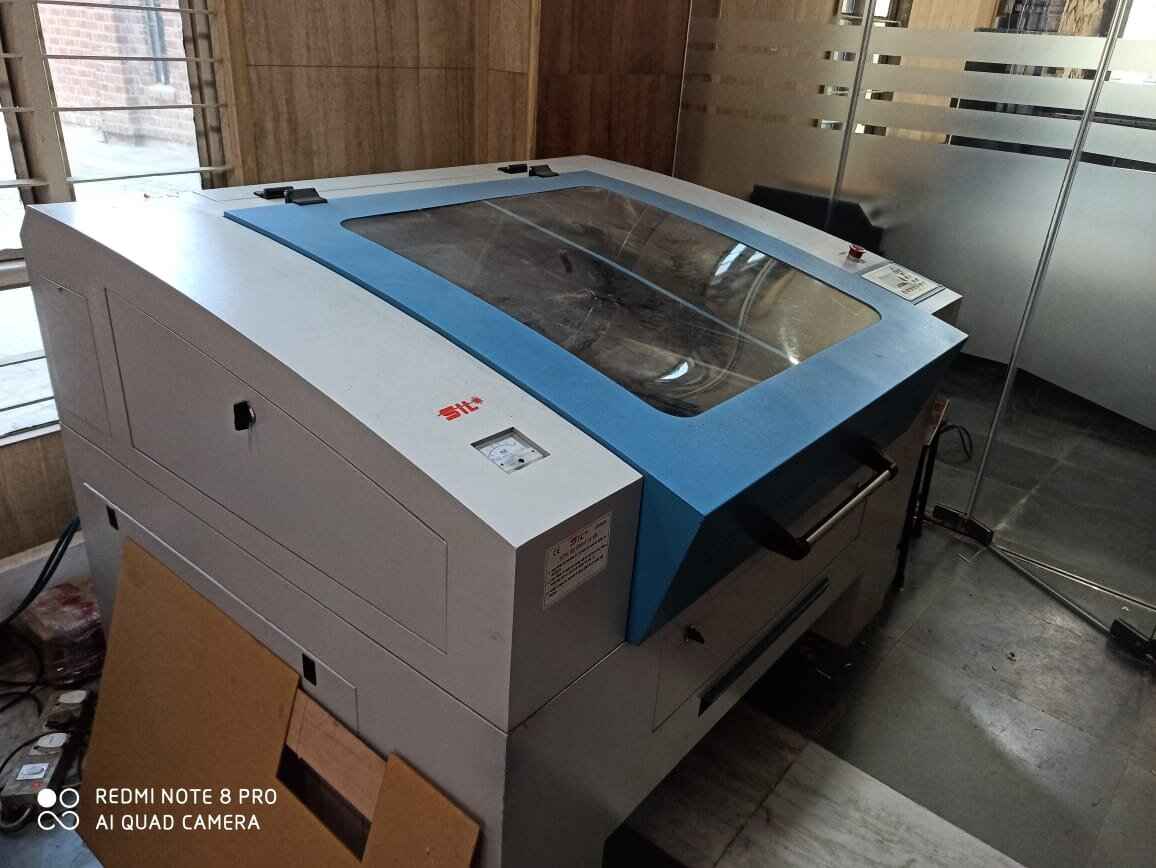
It is a versatile & finds application in art & craft, gift, shoes, toys, model cutting, papers & packaging , wood & MDF cutting industry, interior, decorators and many more. SIL built laser engraver which is engineered
& manufactured in india
The carbon dioxide laser (CO2 laser) was one of the earliest gas lasers to be developed. It was invented by Kumar Patel of Bell Labs in 1964, and is still one of the most useful. Carbon dioxide lasers are
the highest-power continuous wave lasers that are currently available. They are also quite efficient: the ratio of output power to pump power can be as large as 20%. The CO2 laser produces a beam of infrared
light with the principal wavelength bands centering on 9.4 and 10.6 micrometers (μm).
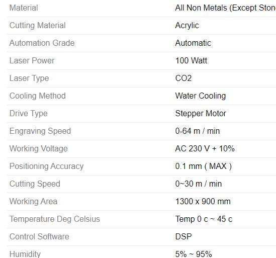
This is a basic spec sheet for laser which provides overall idea for the machine
Software used
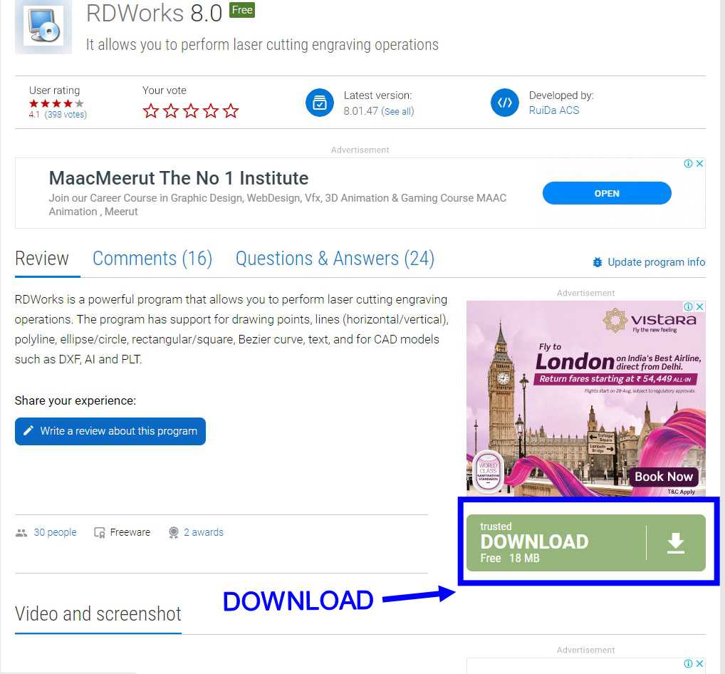
RDWorksv8

RDWorks is a free program that which allows you to carry out laser cutting and engraving processes with ease. RD Works is a design and drawing program which supports drawing points, lines horizontal and vertical, polyline, ellipse and circle, rectangular and square, Bezier curve, text, and formats for CAD models such as DXF, AI and PLT. If you have a Chinese made laser engraver then this a good software package to use and fully supports the Ruida controller. Please contact us if you need any assistance or support.
You can download it on clicking the link given below RDWorksV8Getting started with software
After clicking on the link you will be guided to a site from where you need to download respected software
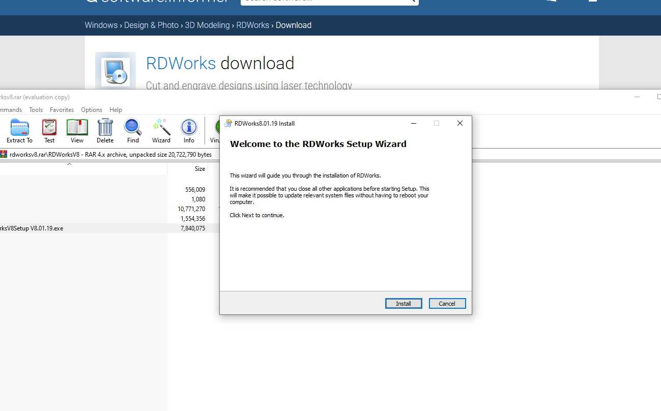
After unzipping the downloaded software start downloading it
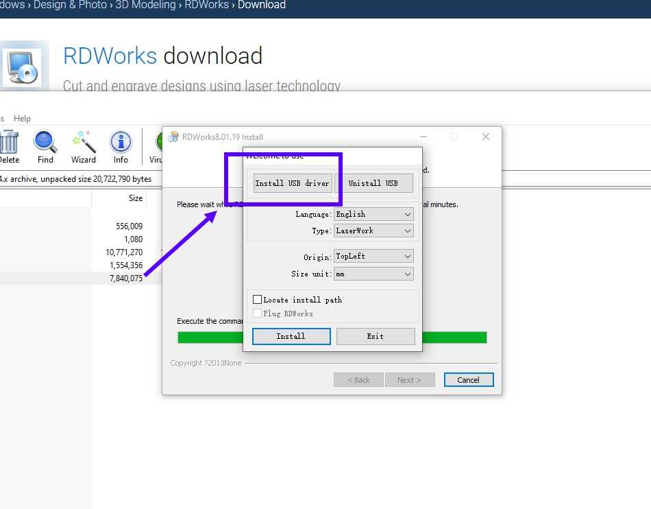
Now this type of menu will pop up and ask you to finally install the software , but you require to add drivers for the software and they can only added when you plug the laser machine to the system , so first connect the USB wire hich is connected to machine
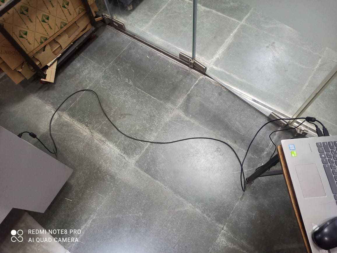
You need to connect the machine exactly like this , for installing driver , then click on the install the driver options and install them
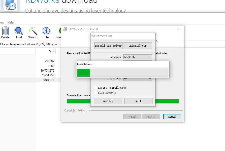
After that click on the 'INSTALL' button in he lower left corner
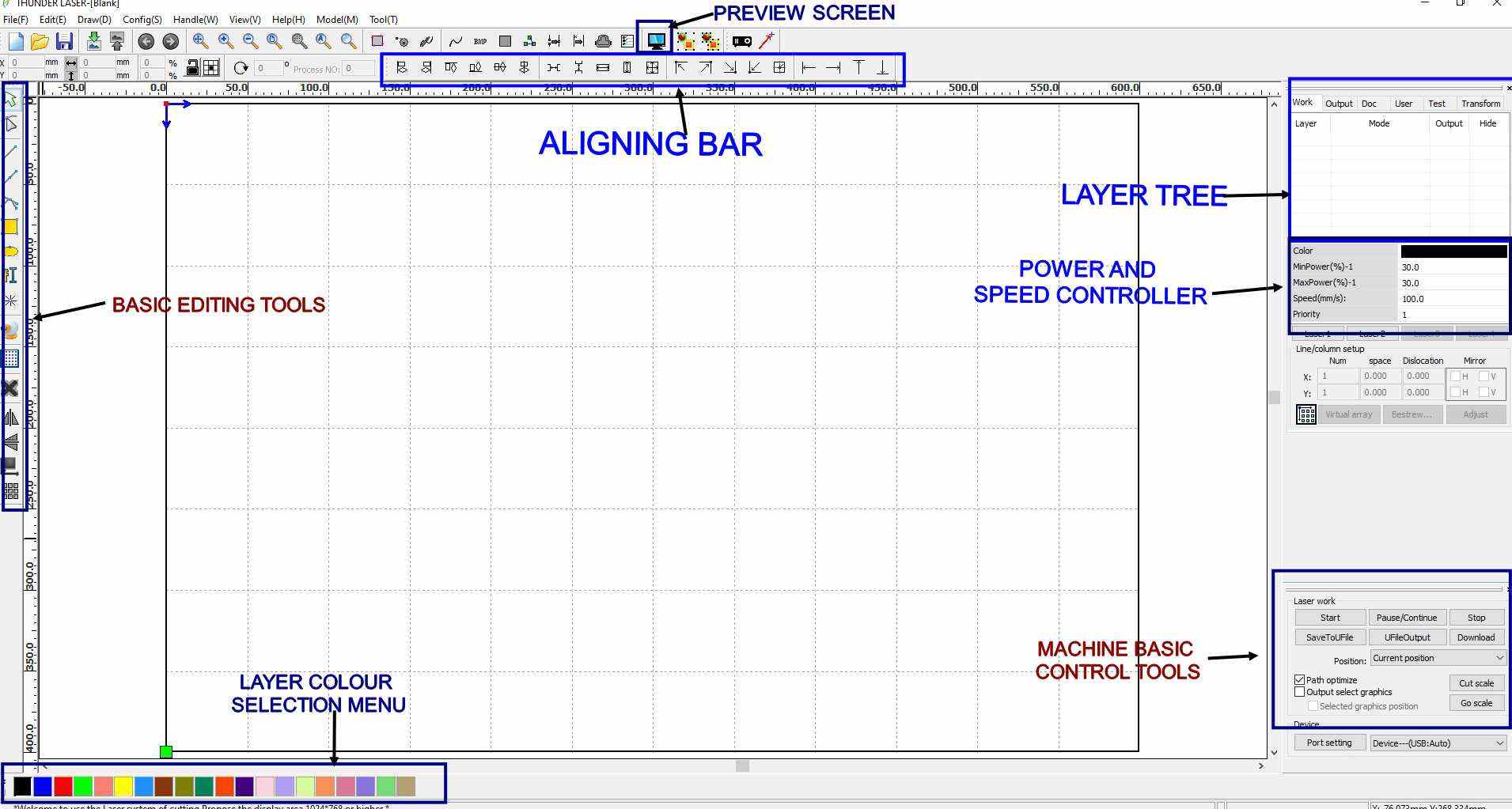
This is a basic oulook of how Rdworks look after instalation
I have given this basic tutorial through which you can easily learn how to work with RDworks
PERSONAL NOTE: No doubt RDworks is an good software but it haves loots of limitation when it comes to designing objects for
                                             cutting so my personal advice is that please restrict yourself from designing things inside RDworks and if possible try other 2D
                                             CAD softwares like AUTOCAD or fusion 360, and then export file from those software for only cutting purpose only ,it will be very
                                             usefull in future
Getting started with machine
SAFETY RULES FOR LASER
* Never leave the laser cutter unattended.
* Only cut materials approved by your instructor.
* Keep the lid closed at all times, unless loading material while the laser is turned off.
* Clean up debris in the laser cutter.
* Identify the fire extinguisher and fire blanket.
For more detail pls ckick on this link
Please go throught this video this is an tutorial for the CO2 Laser machine ,
here i have explained how to startup the mmachine
How to remove the parralax or focusing the beam of machine
Group Assignment:
Performing some basic test
TEST 1 (FOCUSING THE LASER)
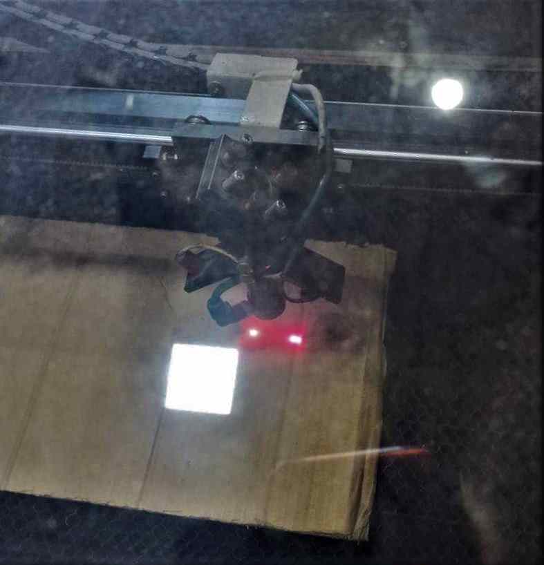
The above image shows unfoced laser pointer
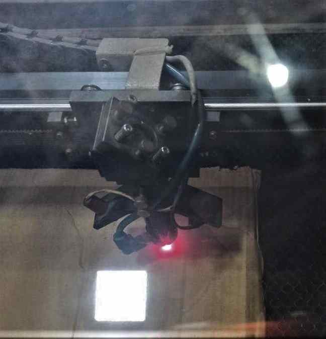
Second image points toward the focused laser pointer(if you want to know how i focused the laser pointer please go through the i have given above)
TEST 2 (Cut and Engraving Test)
This was the second test we porformed as a part of group assignment
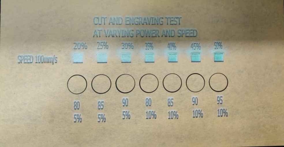
This test was performed by varying speed as well as power to understand a little bit basic about the machine
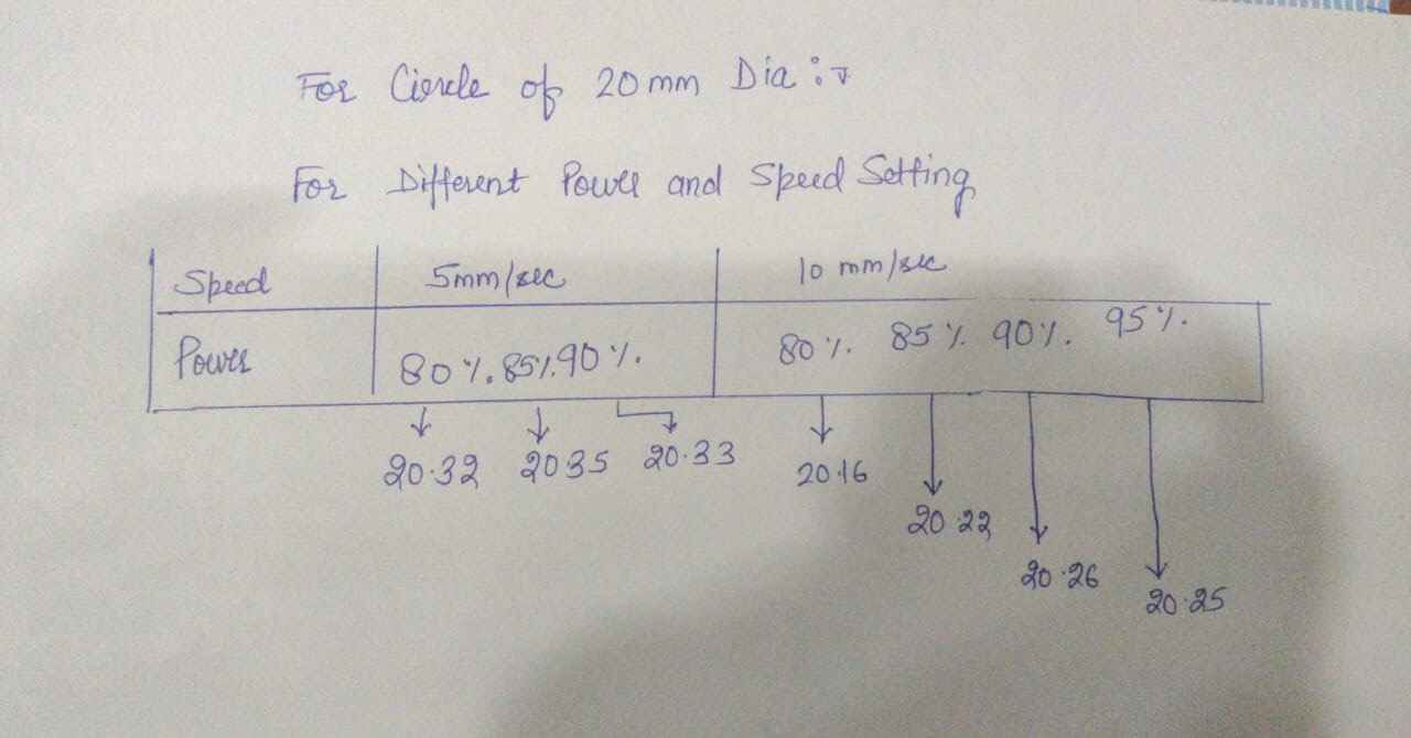
From the test we got outer slots come out to be like the detail in above image and the minimum kerf is in case of Power=80% and Speed=10mm/sec which is 0.16mm
And if you want to download the cut and engraving test you can click on this link for that
cut and engraving testTEST 3 (Measring kerf)
For this test we simply made a a square of 50 mm in RdWorks and cut it by varying speed and power to get best match in which we have least Kerf
* Kerf is defined as the width of material that is removed by a cutting process. It was originally used to describe how much wood was removed by a saw, because the teeth on a saw are bent to the side, so
that they remove more material than the width of the saw blade itself, preventing the blade from getting stuck in the wood. * For more info pls click on this
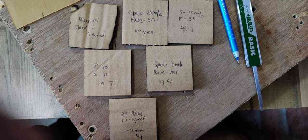
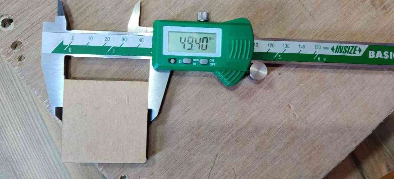
Cutting parrameter
                                           Speed  5mm/sec and Power 25% Kerf= 0.42mm

 Speed 10mm/sec and Power 30% Kerf= 0.3mm

 Speed 10mm/sec and Power 25% Kerf= 0.35mm

 Speed 10mm/sec and Power 35% Kerf= 0.4mm

 Speed 20mm/sec and Power 50% Kerf= 0.6mm
After several test we came to this conclusion that over machine has a kerf of 0.4mm for cardboard of thickness of 4.2 mm and we require to remember while designing
TEST 4 (Engraving / shading Test)
we have selected a 3mm thick transparent acrylic sheet for this test
The purpose of this test is to determine what are different parameter for engraving by varying power and speed .Our main aim is check that
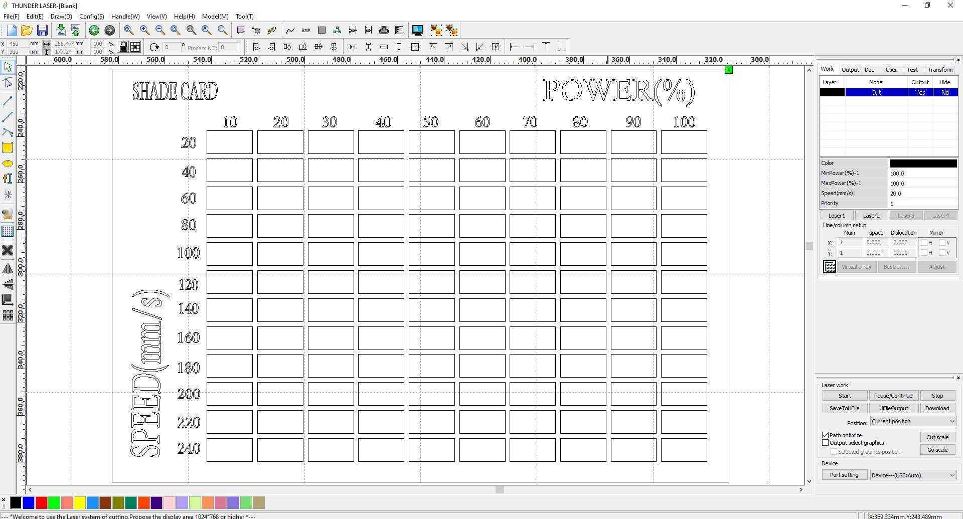
I rwally hate this RDWorks software it never imports DXF file correctly it always causes problem , so i needed to design this shade card in RDWorks which was really pain in ass.
and the biggest headache was that ,giving different values for every shaded box because every box is different from 1 and another and no 2 boxes have same cutting parameter
So solution for this problem , i used to fix one parameter like speed and varry power for every consecutive box and at a time i wont able to give parrameter for boxes no more then 19 as RDWorks only offers19
different colour , but row by row i got it right
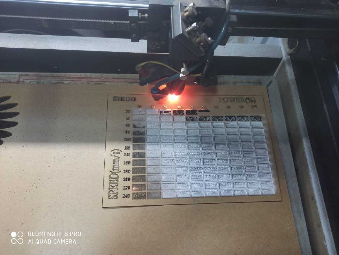
It tool a quite a few time to prepare the shade card
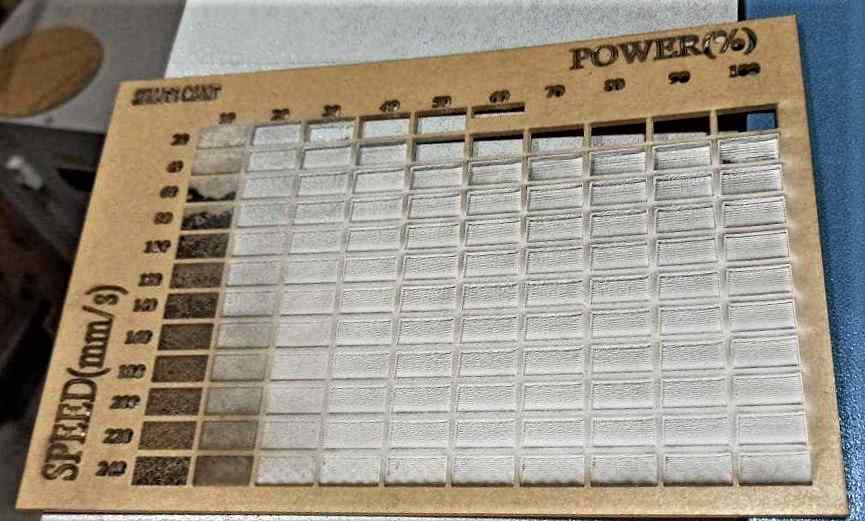
This shade card will be very usefull in future for the students , because when they want to engrave or shade something , they can look to this shade card and decide which depth of shade is required for his work and on what power and speed it is made
I am attaching RdWorks downloadable
Shade card (RdWorks)Shade card ( DXF / DWG )
Individual Assignment:
For this weeks individual assignemtn we were asked to make parametric pressfit kit , with keeping kerf given by our test in our mind.
Parametric design involves engineers building up a 3D geometry piece by piece. 2D sketches turn into 3D features, with constraints and relations duly applied to fit the designer’s intent. However, since each step
follows from preceding steps, parametric design can require careful planning. The feature-based parametric modeling technique enables the designer to incorporate the original design intent into the construction
of the model. The word parametric means the geometric definitions of the design, such as dimensions, can be varied at any time in the design process. Parametric modeling is accomplished by identifying and creating
the key features of the design with the aid of computer software. The design variables, described in the sketches and described as parametric relations, can then be used to quickly modify/update the design.
Then we proceeded to make our individual assignments.
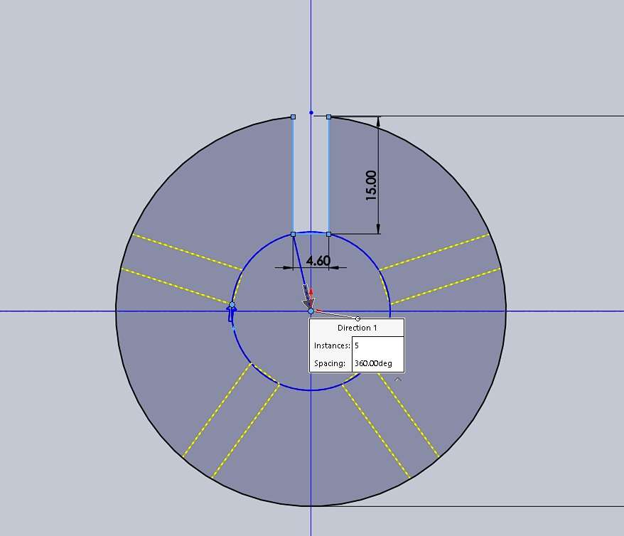
I used SOLIDWORK 2018 as my designing software as i have a good understanding of how to work with this software and i make a 50mm diameter circle
* From the test 3 , which we did previously we came to know thatour machine provide kerf of 0.4 mm so i take that in account while designing and make it 4.6 mm as 4.2 = 0.4 mm of Kerf + 4.2 mm thick
sheet
* And make the length of slots 14 mm long (Well i want a good fit so i did that , its my personal choice)
* I used the ARRAY command and make 5 identical slots around the circle.

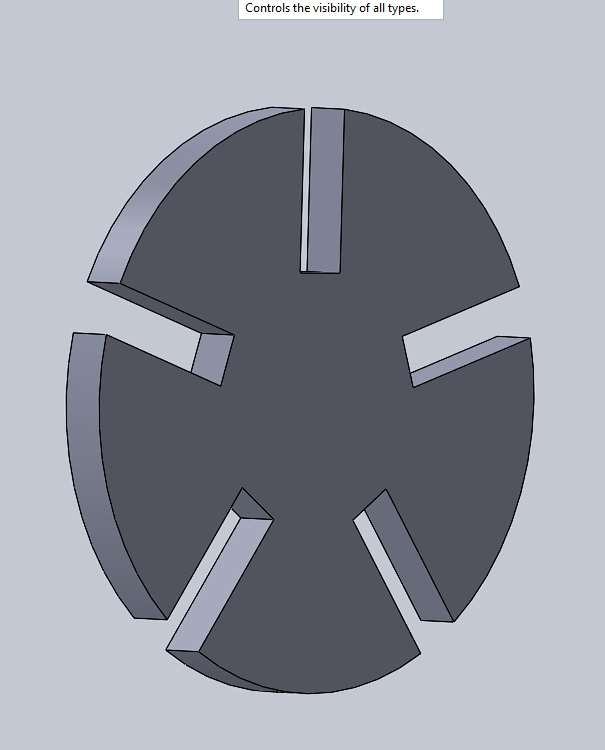
You can see the extrude image of the press fit kit.
Well SOLIDWORKS has parametric feature based tool as if we want to make a model, it can be controlled by parameter,dimension and geometric constraint.
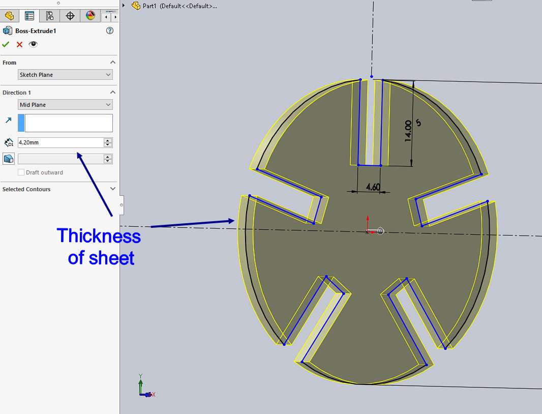
From this image how i can provide the dimensions according to a 4.2mm sheet and easly provide slots for that
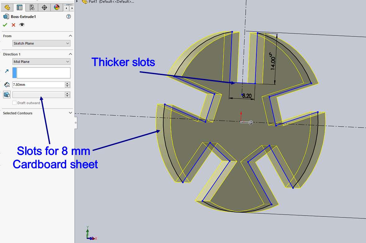
And this image shows if i require to make the same pressfit kit in 7.8mm cardboard , i only require to change only few settings and the slot will be change
Cutting parameter:
MinimumPower(%) : 100
MinimumPower(%) : 100
Speed (mm/s) : 25
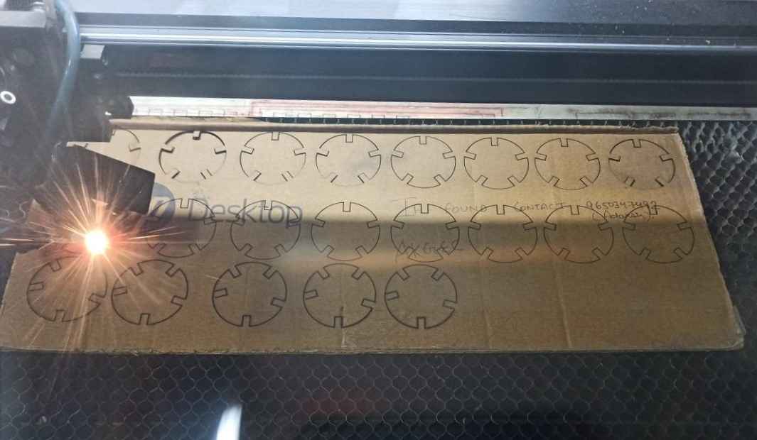
Well to save space i alligned them them very well so less material wastage can happen
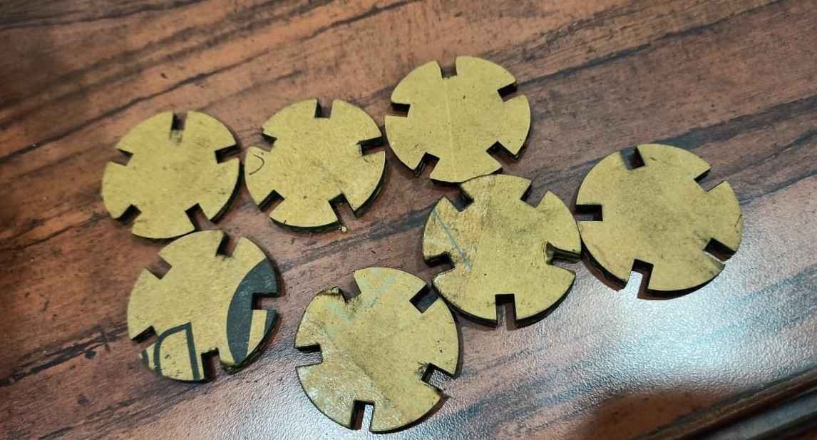
Now i got all the pieces now i have started joining them
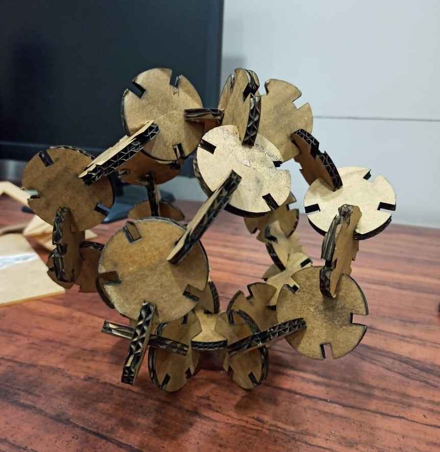
Well i got good interference fit for my press fit kit
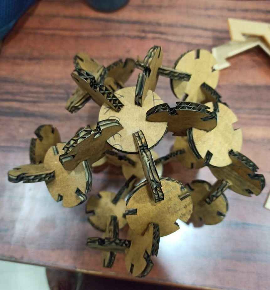
This will be my hero shot
And if you want to download the CAD editable file you can click on this link for that it contains solidworks file , stl , dxf file as well
pressfitFAB FILTER MARK 1 by
PULKIT TALWAR is licensed under
CC BY-NC-SA 4.0
![]()
![]()
![]()
![]()