WILDCARD WEEK
This week we are goimg to use any process of our choice. The requirements of this week are written below
Design and produce something with a digital fabrication process (incorporating computer-aided design and manufacturing) not covered in another assignment, documenting the requirements that your assignment meets, and including everything necessary to reproduce it. Possibilities include but are not limited to wildcard week examples.
After thinking about the availaible possibilites we found that learning PLASMA CUTTING will be good for this week. We haave used laser cutter in the previous assignments and it has its own limitations like the laser we have is not suitable for metal cutting operation. So we chose to work on the Plasma Cutter this week.
Plasma Cutter is availaible In one of the labs of AKGEC and we took the permission of the required personnel and went ahead.
Messer Cutting Systems Smart Blade
Specifications
Technical Data (dimensions in mm)
Working Dimensions 1500 mm width X 3000 mm length
Working Height: 700 mm
 Positioning Speed:12m/min
Plasma Possibilities:Hypertherm Powermax 45/65/85 or Kjellberg Cutfire 65 i
Maximum Plate Weight:247 kg/m corresponds to structural steel of t=6mm
Machine Foot Print: 2500 mm Width X 5000 mm length
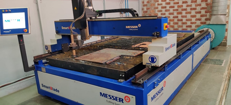
The size of the machine is very large and we can cut very large piece of metals on it. It can cut upto 10mm. I always wanted to grab a hand on this machine and with the wild card week i got this oppurtunity to wot on it.
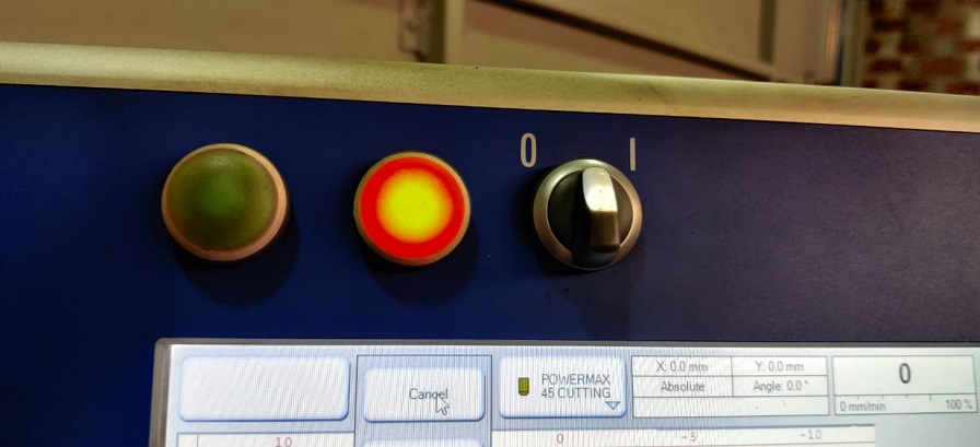
The machine has a monitor with it which acts as the interface with the machine. It has a green red and black button. Bkack button is used to switch on the machine.
The green button is used to move the plasma as per the program
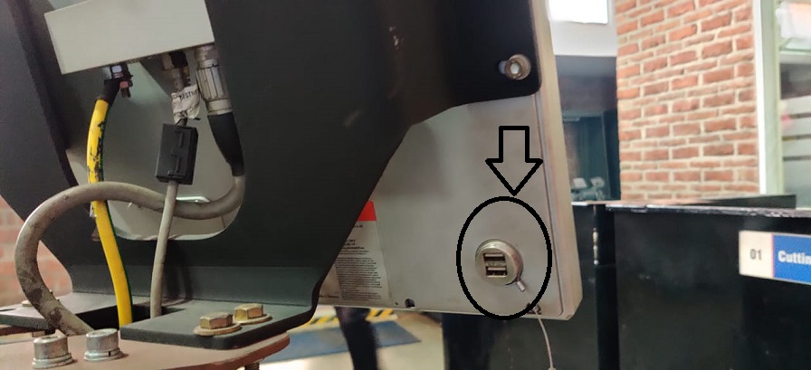
Just behind the monitor you will find the usb plug in. You can bring your program in the DXF format and cut it over the machine.
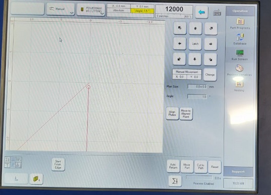
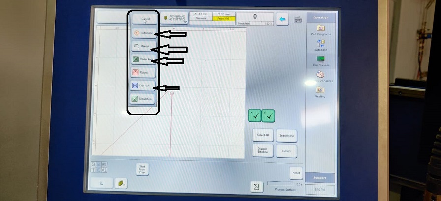
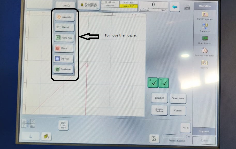
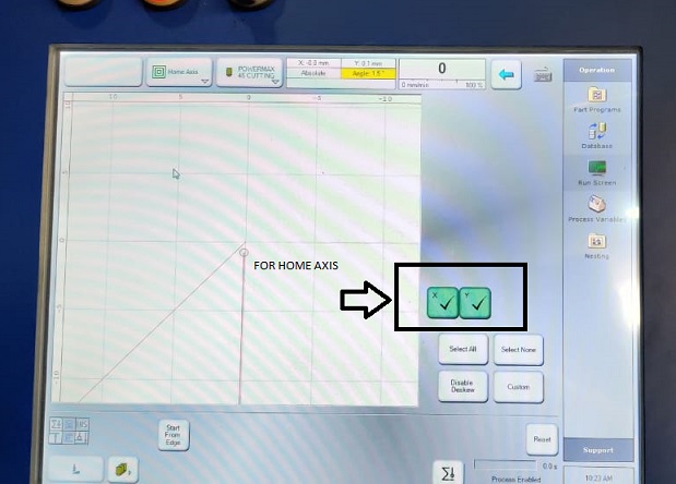
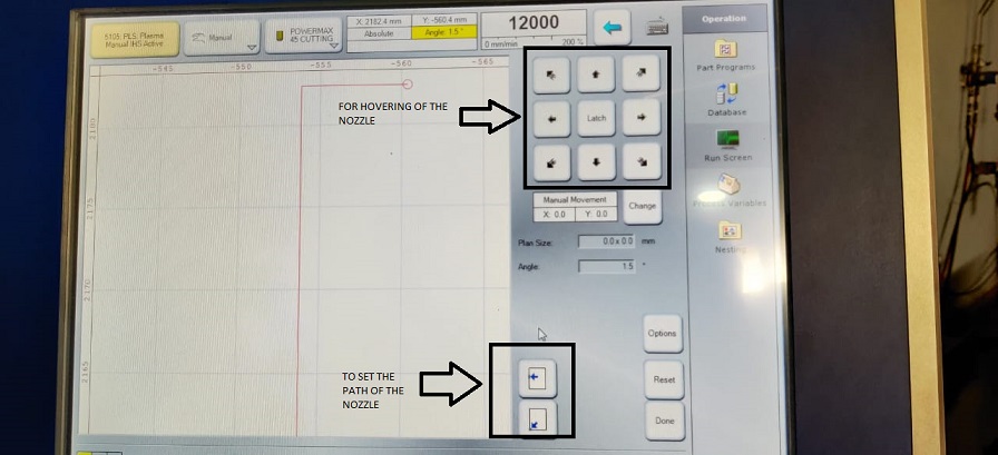
The monitor is a touch screen. You will see options to move the machine nozzle. By clickiong Home Axis the machine will move to home axis. you need to keep this in mind that there should not be any person standing besides the machine when it is moving.
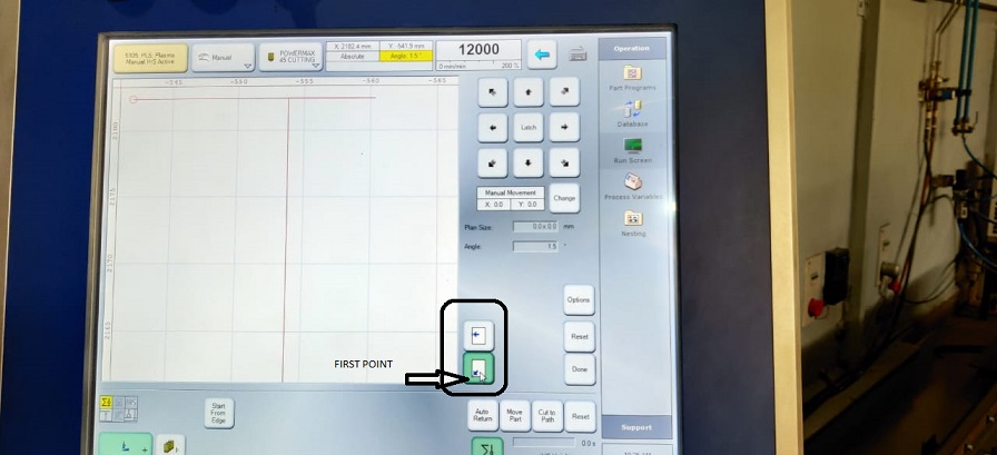
By clicking manual you can manually hover the nozzle over x and y axis.
Dry Run button is used to give a dry run of the nozzle which means that the nozzle will move according to the program but plasma arc will not be generated.
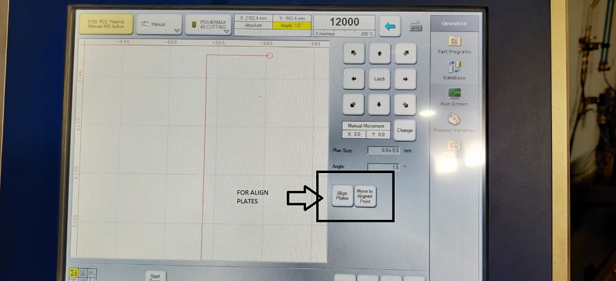
There are times when the sheet is very heavy and its alignment takes a heavy toll on you. So there is an option to align the nozzle movement according to the position of the plate by giving it the location of the axis.
You can see if the alignment is proper or not by clicking on gthe align plate button.
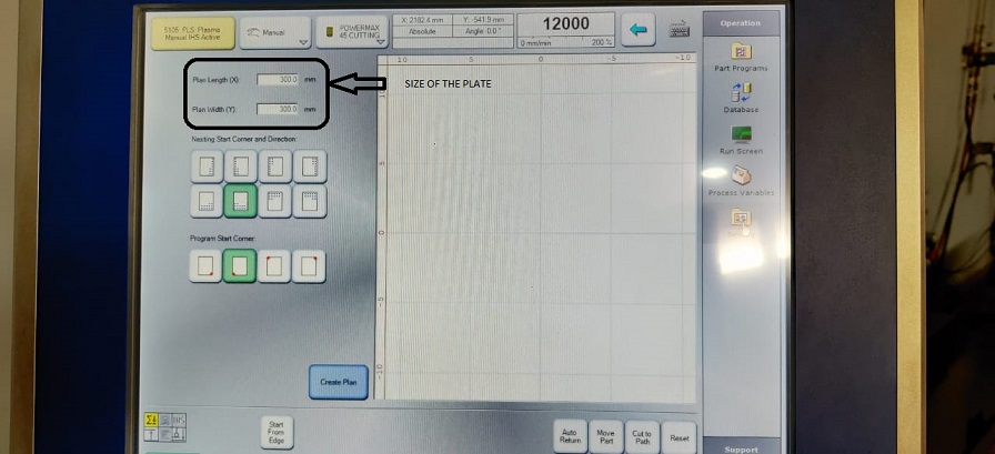
Then there is a button on the right side of the screen known as NESTING where you put your file and giv ethe dimesions of the plate which you are going to use. There is an option of inner contour and outer contour. When aver you give a file and if that starts to cut from the desinged point then there are chanced that it will not properly cut for that you need to give it a contour which is an extra distance given to the nozzle to travel so that it cuts the designed part properly.
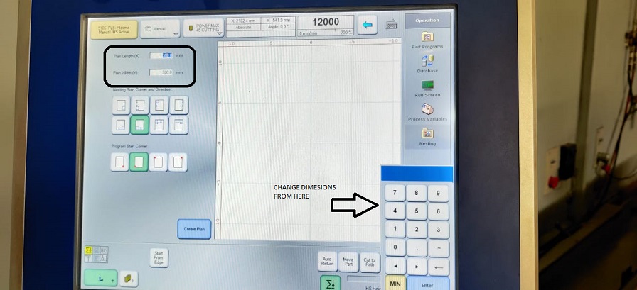
You will see the option to give the dimesions of the plate. The interface is very user firndly and you can easily enter the number for the dimesion of the plate.
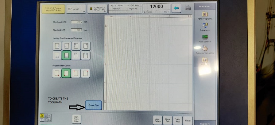
Then you need to click on create plan option which will lead you to define the inner and ouetr contours.
As you click on the create plan option you will see that the option for the distance between parts is asked and that is applicable when you cut multiple parts over it.
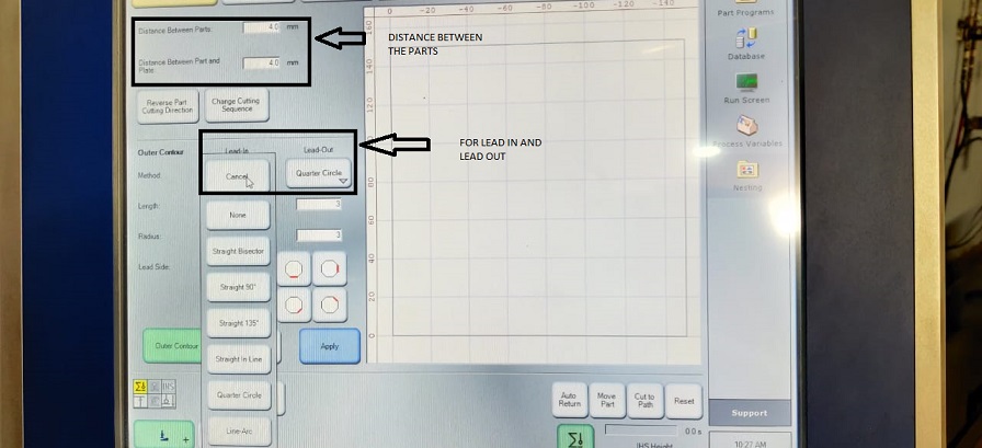
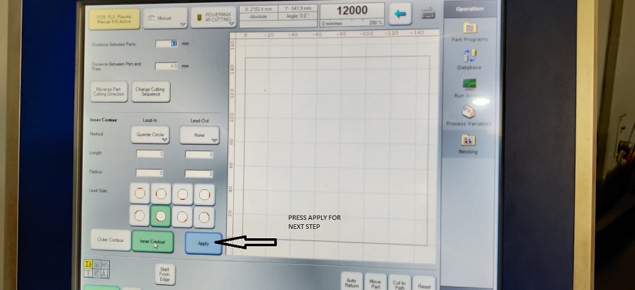
Then thereis an option of inner contour and outer contour and lean in and lead out. These are the extra distance which the nozzle travel apart from the design. Because when if the nozzle starts from the design point then the cut is not complete so we need to give it extra contour on inner and outer side. for lead ion and out we have selected quater circle but we could have used the other ones also.
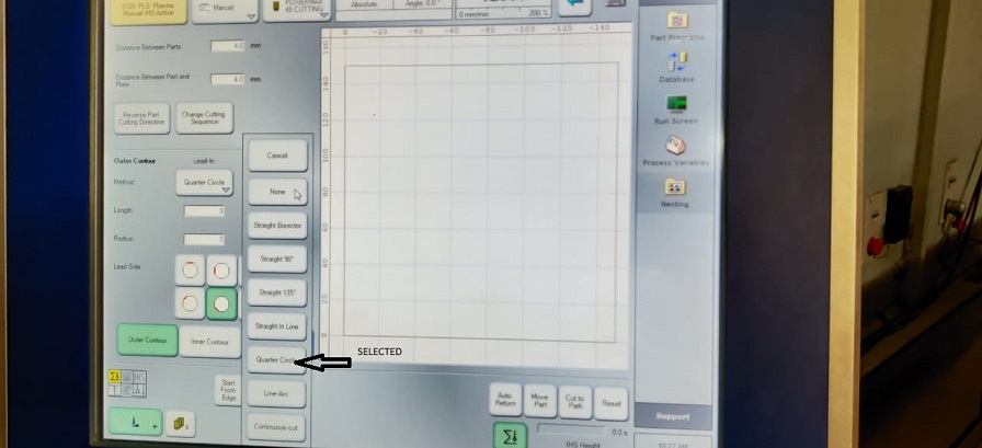
Here you can see the options for the contour and the lead.
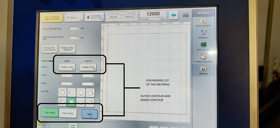
click on the option of APPLY for the next step.
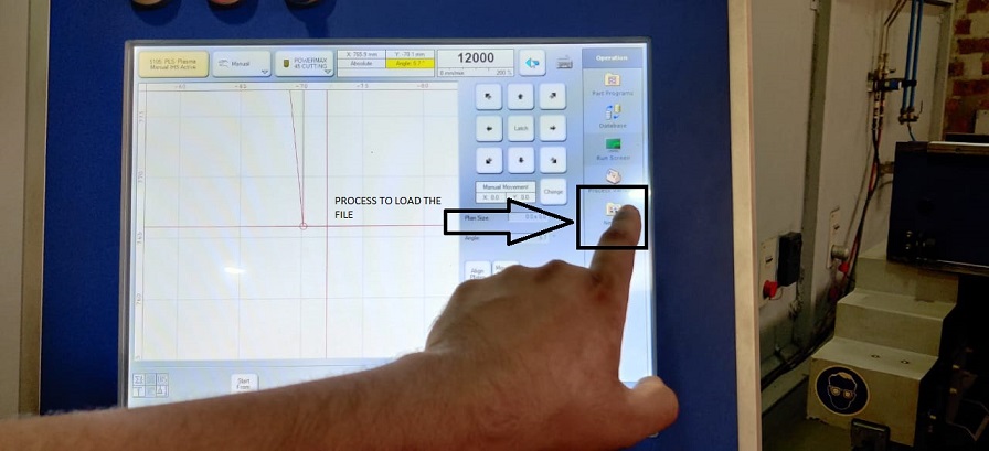
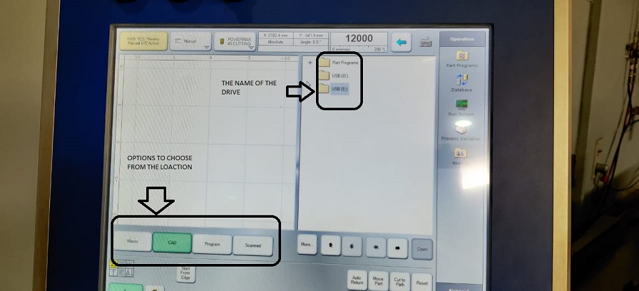
Here you see the options for the to choode from the various locations from where you can take the files from that location. so if you have a pandrive with you , you then need to click on CAD and them option the USB and search for the loaction of the file.
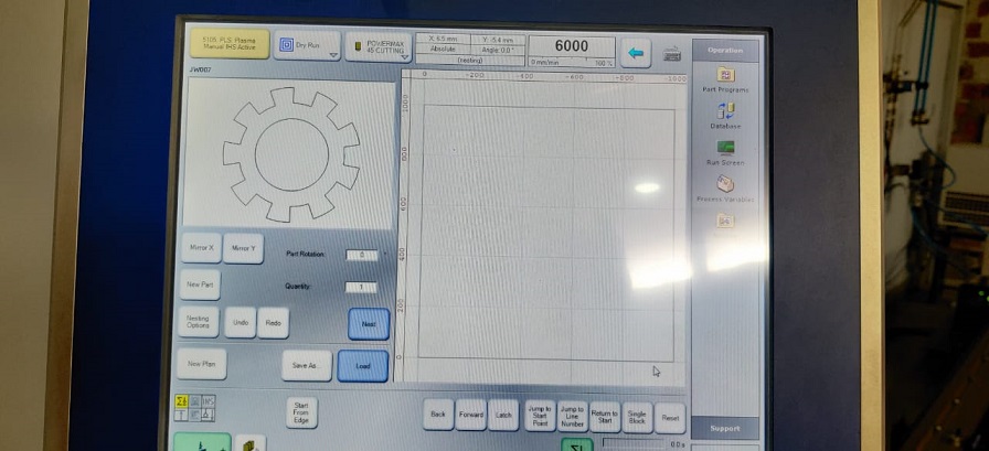
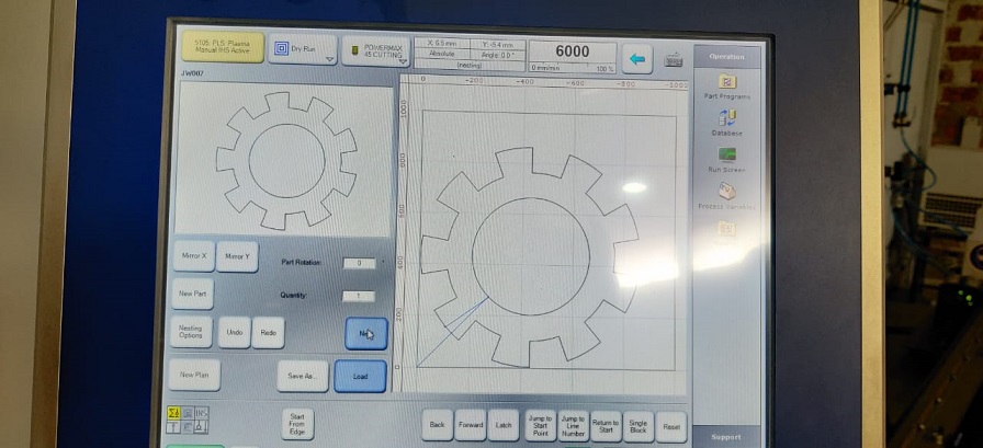
As soon as you load the file on the machine you can see the picture of the design on the screen and then you need to press load for the next step.
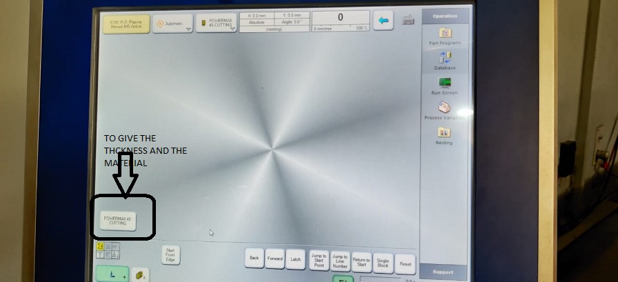
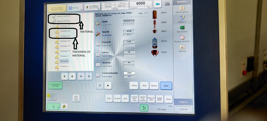
Now you need to provide the cutting parametrs like the thickness of the material which you are going to cut and the name of the material.
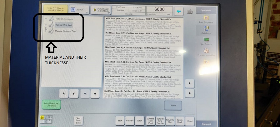
Below every material you can see the thicknesss of the sheet and for every thvikness the nozzle adjusts its power and it cuts the sheet through.
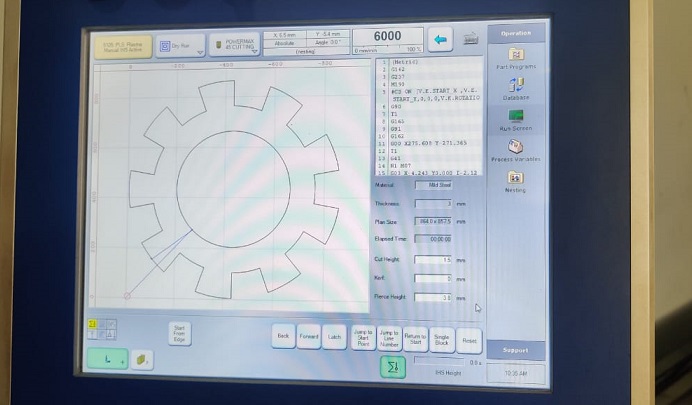
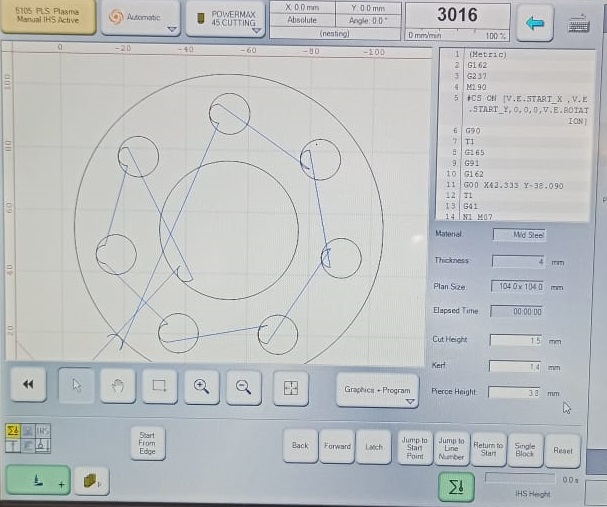
When all the above mentioned processes are done then you will see the G codes on the right of the screen for the tool path.
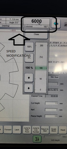
you can adjust the speed of the nozzle by this option and one more good thing with the machine is that you can change the nozzle height while the nozzle is cutting the material.
After the cutting we have to shut down the machine for which you need to click on the HMI control and then the Shut Down control.

Test Cut 1
The test cut file was made by Afsha and we tested it on the Plasma machine. The machine is very big and we conducted the test under the observation of a lab assistant. The test conducted at first was not upto the mark and then after few days we again conducted the test with a new nozzle and parameters and the test piece came out well. I have explained all it in detail.
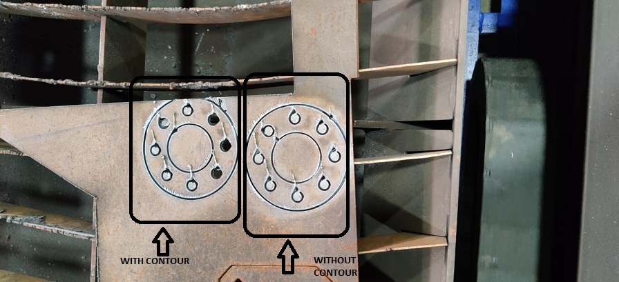
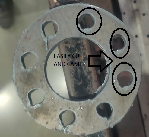
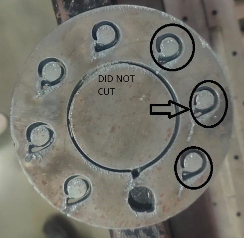
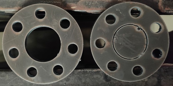
This is the test cut we did on the mild steel sheet of 4mm thickness. The feed rate varies accordingly with the thickness of the sheet . In our case the feed rate is 3106mm/min. In the image you can see that the holes did not come out. The one where no holes are out is without inner and outer contour. The second one is with outer contour only but no inner contour.
Outer Contour and Inner contour
We always want out piece to be neat and clean and without any error in the dimensions and also want that it comes out very easily out of the matetrial stock when cut. All these properties are achieved when we provide inner and outer contour with lead in adn lead out. Outer contour is when we want to cut a circle and the circle will satrt to cut from a point away from the designed circle. The point where the cut will start will be determined by the value of Lead in and the point where the cut will stop will be detrmined by the lead out value.
The process for the value input for lead in and lead out is explained in the upper part of this page.
Lead in and Lead out
The lead in and lead out are used for the motion of the plasma nozzle. If we want to cut a hole in a piece then we have to provide lead in and lead out at the inner contour. Inner contour means that the inner portion is not of our use and the periphery of the hole will come out clean.
The lead-in and lead out for the outer contour is used if the blank is of our use. For the blank we have to give the Lead in and lead out at the outer contour. The outer contour facilitates perfect blank.
In the test piece Number 1, toolpath was made such that there was no Inner contour. But outer contour was given for lead in only and lead out was not given for outer counter.
In the test piece 2, LEAD in and LEAD out was given and then we could see the difference that the cut was very proper and easy removable.
The holes at the periphery were cut with the outer counter and lead in and lead out beacuse of which the shape of the hole is distorted.
The holes would have come perfectly if the holes had inner contour with lead in and lead out in it.
Test cut 2
The test cut 1 was done and some of the important things like unifrom lead in and lead out at outer and inner contour were not given properly as we had very less knowledge about that. But then as per the reviews given by our local evaluator, we thought of changing the nozzle of the plasma and again do the test cut. This time the cut we obtained was very improved as compared to the test1. The changes we did in the new test cut is that we gave the lead in and lead out for inner and outer contour and all the features came out well.
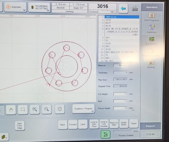
You can see the inner contour and outer contour in the tool path.
When the machine starts a red line starts to appear which shows the path on which the nozzle is moving.
The test cut 2 parts have very less burrs as comapred to the test 1 parts. Due to the presence of rust over the surface of the mild steel, the inner circle of could not cut in the first attempt. But in the second attept the cut was proper.
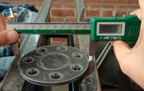
The dimensions obtained in the test cut 2 were nearly exactly the same as given in the design file. The kerf can be seen on the cut surface in the z axis. The taper form is obtained on the z axis so you cannot take that kerf into consideration while designing the part.
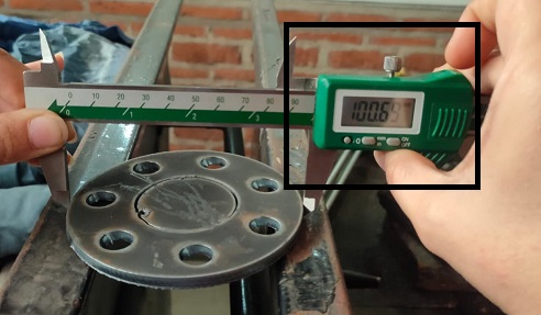
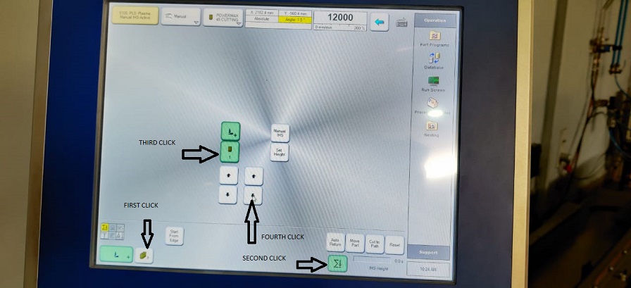
The z axis is calibrated thriugh a sensor placed on the nozzle. it toiches the surafce and coes up by 10mm.
The sheet we used for the test cuts was the wasted one and we could see the rust on it because of which the plasma was tripping and it was a failed cut for us.
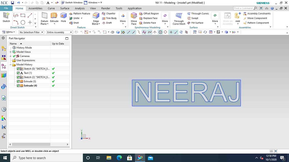
For plasma cutting, a design should be there to cut so i chose to cut my name on the mettalic sheet.
So to design the part which i am going to cut in this week i will be using NX software again. You can see this page to get through the concept of the design.
So it was required to design the plate in such a manner that the name comes out easilty without any difficulty. Initially we designed the plate as shown on the figure below and my colleague afsha also made the name in the similar manner but when she cut her name it was found that the A just fell downwards and it didnot look the way we wanted that to look.
Then i changed my design in a way that the name appears an it takes support from the side walls. But If convert the dxf of a 3d design then the toolpath which is made takes two paths of one line which is not a problem in the case of the laser machine but its a problem in case of the plasma because the palsma onle works when it senses the material beneth it and if there is any void space pressent then the cut will stop.
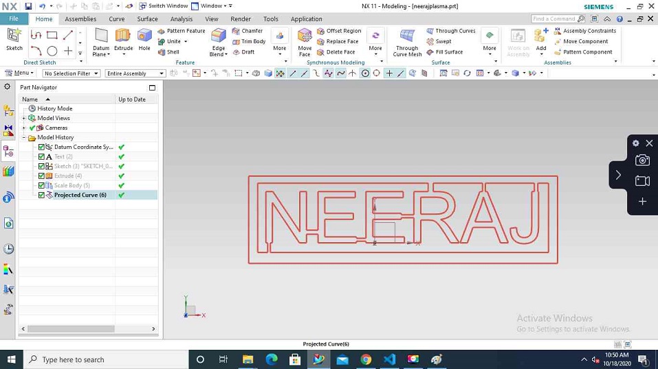
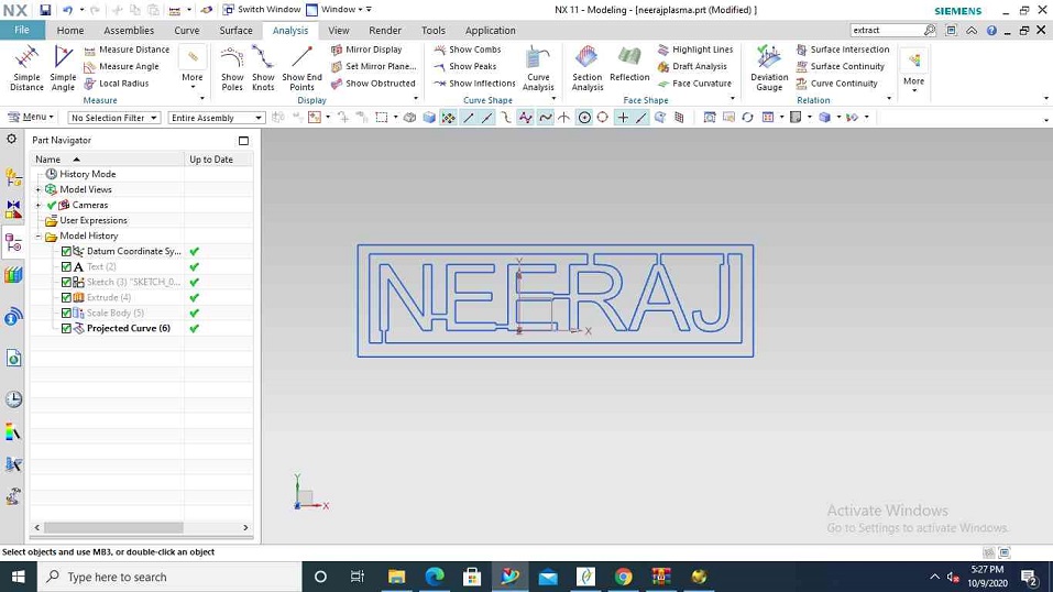
So we thought of projecting the curve from the 3d design into a 2d curve and then exporting it into a dxf format.
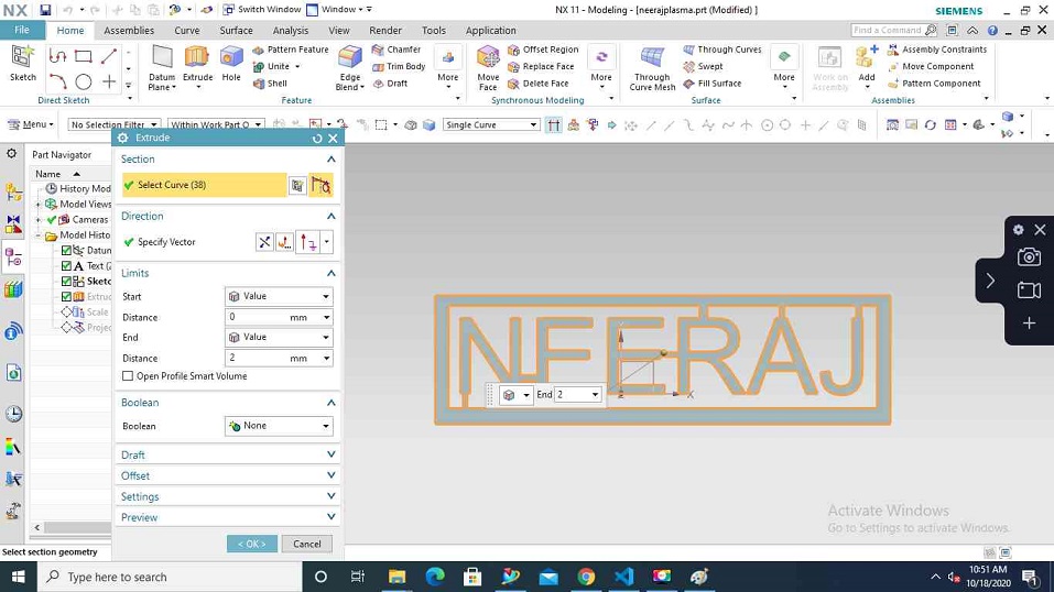
And the plan worked and i got a 2d design out of the 3d name .
Download files
When i went to cut the file in DXF, It started to cut and then sudenly stopped and again i tried to work opver it but it showed that there is somethinhg wrong with the file.
Afsha also had her file and there also it showed an error while cutting.
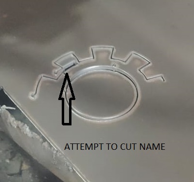
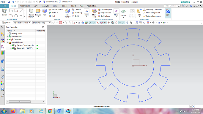
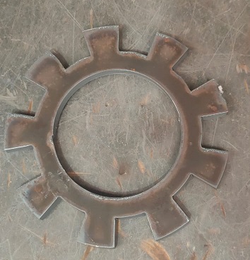
I tried to think over the isseue but could not find out the reason. Perhaps it is due to projected curve that made it in this manner. The design was having an issue as the dxf which was imported could not be read by the machine. I had projected my name and then made a 2d sketch out of that so i think that could be the reason why the name did not cut. I had done itirations and afsha also did the same with me but to realise that the DXf is not read by the machine. But since we had only limited time to access the machine. I hurriedly made one more design in a 2d format and then exported its PDF. This time i thought to make something related to mechanical so i made a design of a gear whcih did not took me much time .
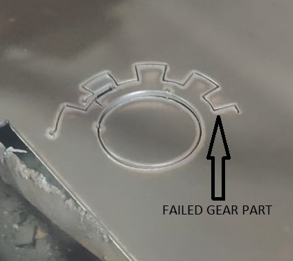
The gear was desinged and i hurriedly went back to the plasma machine, we have an instructor with the plasma machine since it can be dangerous also to play with plasma. This time it started to cut but it again stopped in between. The reason was that it started with the same point where i was trying to cut and it sensed an empty space and the other reason which the instructor told me that the nozzle is very old and it trips sometimes.
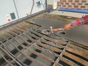
But in the next attempt i was able to cut the gear but not easily. I had to use the hammer to remove it from the bed.
Download gear files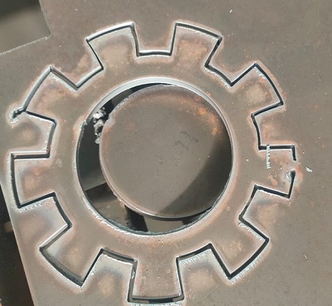
HERO SHOT
So i designed a gear for my individual assignment and cut it on the plasma as my individual assignmant and here is the HEROSHOT of it.
Cutting video
Tool path checked on RDworks to make sure it doesnot run twice
General Mistakes
The machine will not cut if the size of the design is greater than the size of the plate mentioned . The machine has an issue that it will not tell you what mistake has happened it will just show you that it is not working.
You need a have the surface of the metal free from any kind of rust. Nozzle sensing rust lowers its working efficiency and it will also trip in between making the life tougher for the operator working on the machine.
Always export DXF of a 2d file and never with a 3d file as the toolpath repeats whcih does not work in the case of the Plasma machine.
The Gear cut during the assignment is the individual assignment