Input Devices
Individual assignment:
measure something: add a sensor to a microcontroller board
that you have designed and read it
Group assignment:
Probe an input device's analog levels and digital signals
This week it is required to read about the different sensors availaible and use them to read the input through the board made in the previous week or make a board for the sensor.
Since there is a lockdown and i dont have access to any equipment, i decided to simulate the process in tinkercad.
I chose the ultrasonic sensor to go with the simulation.
What is Ultrasonic sensor
How is the ultrasonic Sensor works ?
-
Ultrasonic sensor has 4 Pins, 1. VCC / 2. Trig / 3. Echo / 4.GND
-
The VCC stands for 5V Supply, Which powers the sensor, typically with +5V
- The Trig stand for Trigger Pulse Input,This pin has to be kept high for 10us to initialize measurement by sending Ultrasonic wave.
- The Echo stands for Echo Pulse Output,This pin goes high for a period of time which will be equal to the time taken for the Ultrasonic wave to return back to the sensor.
- The GND stands for 0V Ground, Which is connected to the Ground of the system.
The Ultrasonic sensor features :
-
Operating voltage: +5V
-
Theoretical Measuring Distance: 2cm to 450cm
-
Practical Measuring Distance: 2cm to 80cm
-
Accuracy: 3mm
-
Measuring angle covered: <15°
-
Operating Current: <15mA
-
Operating Frequency: 40Hz
How does the Ultrasonic sensor works ?
-
This particular sensor works with the simple high school formula that Distance = Speed × Time
-
The Ultrasonic transmitter transmits an ultrasonic wave at a frequency too high for humans to hear, this wave travels in air and when it gets objected by any material it gets reflected back toward the sensor this reflected wave is observed by the Ultrasonic receiver module, then the sensor calculate the distance based on the time required .
-
I have found out that radar and ultrasonic sensors can be used for some of the same purposes, sound-based sensors are readily available, they can be had for just a couple dollars in some cases and in certain situations, they may detect objects more effectively than radar.
Advantages of the Ultrasonic :
-
Ultrasonic sensor has a feature in which this particular sensor has no problem with the colour of the material they are sensing.
-
At 20°C (68°F), the speed of sound is 343 meters/second (1125 feet/second), but this varies depending on temperature and humidity.
-
Specially adapted ultrasonic sensors can also be used underwater. The speed of sound, however, is 4.3 times as fast in water as in air, so this calculation must be adjusted significantly.
Disadvantages of the Ultrasonic:
- The Ultrasonic sensor has a problem if the material that is being sensed absorbs sound or its being shaped in a way that it reflects the sound waves away from the receiver and by that the readings will be unreliable.
Process of TinkerCad for Simulation
The basic process of simulation on the Tinkercad is explained in week 9 of the embedded programming. In this simulation i have downloaded the code from the arduino site for the ultrasonic sensor and made some changes on it. I have used a RGB LED and programmed it to blink at different colors according to the distance measured by the ultrasonic sensor.
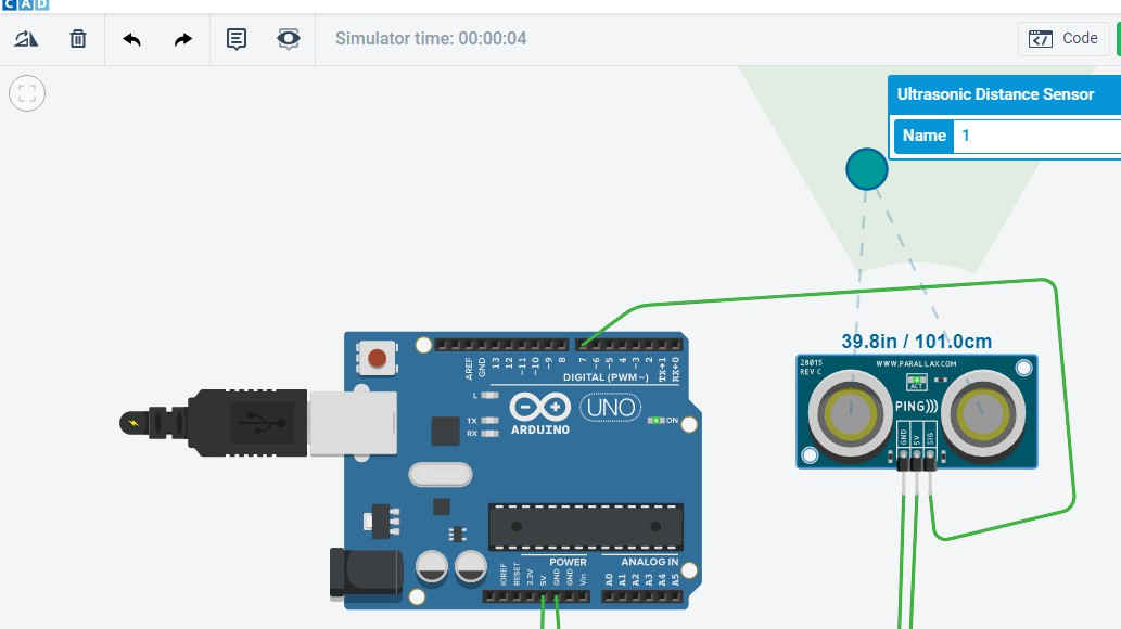
Initially i thought of just make a connection of the sensor with the Arduino and then take its output by programming it.
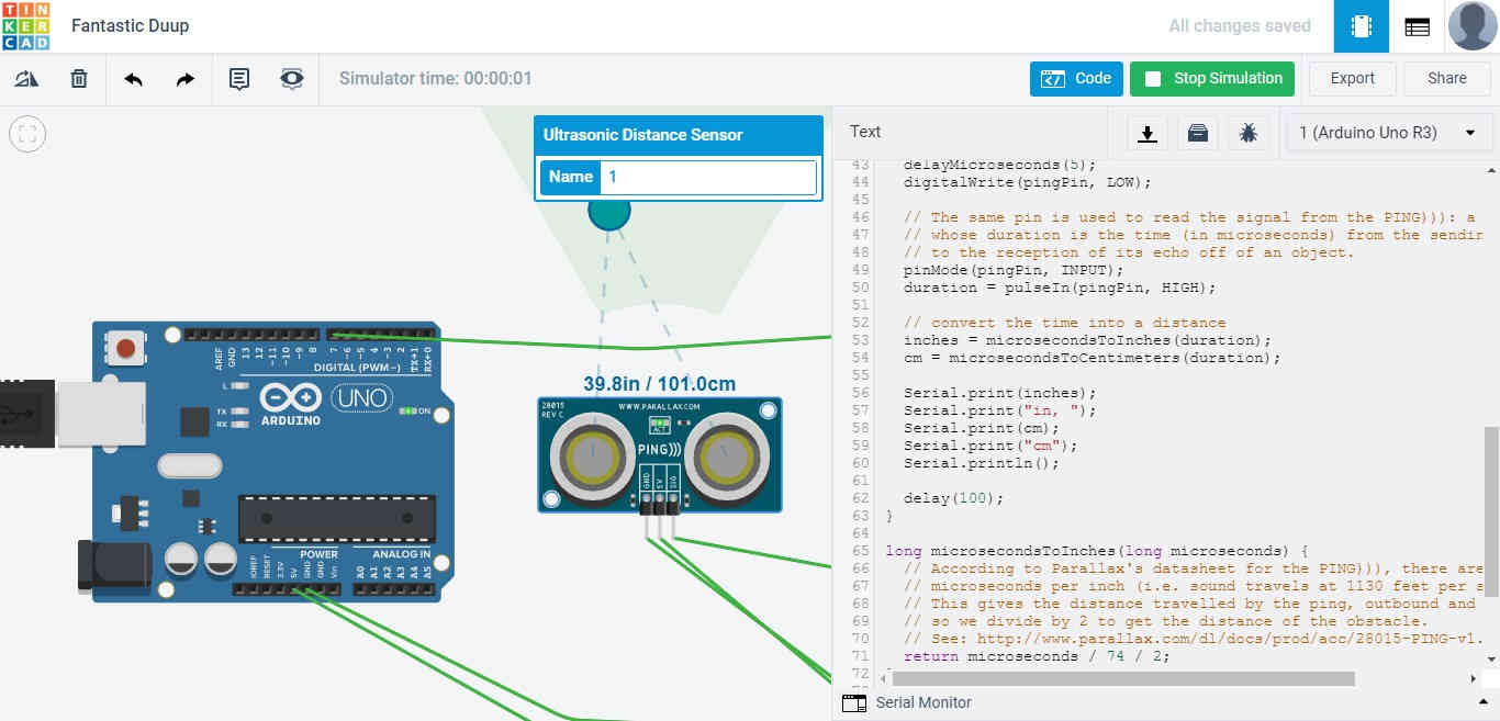
The program is downloadable from the arduino site.
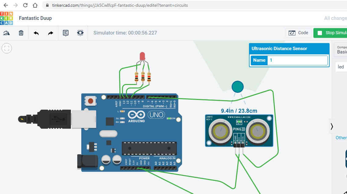
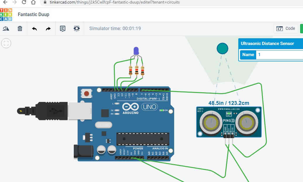
Then a circuit is made with RGB led which will glow with different distances. The program is in such a way that RED color will glow for distance less than 10, Blue for more than 10 and less than 50 and green for more than 50 inches.
const int pingPin = 7;

int red=13;

int blue=12;

int green=11;


void setup() {

  // initialize serial communication:

  Serial.begin(9600);

  pinMode(red,OUTPUT);

  pinMode(blue,OUTPUT);

  pinMode(green,OUTPUT);

}


void loop() {

  // establish variables for duration of the ping, and the distance result

  // in inches and centimeters:

  long duration, inches, cm;


  // The PING))) is triggered by a HIGH pulse of 2 or more microseconds.

  // Give a short LOW pulse beforehand to ensure a clean HIGH pulse:

  pinMode(pingPin, OUTPUT);

  digitalWrite(pingPin, LOW);

  delayMicroseconds(2);

  digitalWrite(pingPin, HIGH);

  delayMicroseconds(5);

  digitalWrite(pingPin, LOW);


  // The same pin is used to read the signal from the PING))): a HIGH pulse

  // whose duration is the time (in microseconds) from the sending of the ping

  // to the reception of its echo off of an object.

  pinMode(pingPin, INPUT);

  duration = pulseIn(pingPin, HIGH);


  // convert the time into a distance

  inches = microsecondsToInches(duration);

  cm = microsecondsToCentimeters(duration);

  if(inches < 10 {
    digitalWrite(red,HIGH);

    digitalWrite(blue,LOW);

    digitalWrite(green,LOW);

  }

  if(inches>50){

    digitalWrite(red,LOW);

    digitalWrite(blue,LOW);

    digitalWrite(green,HIGH);

  }

  if(inches>10&&inches>50){

    digitalWrite(red,LOW);

    digitalWrite(blue,HIGH);

    digitalWrite(green,LOW);

  }


  Serial.print(inches);

  Serial.print("in, ");

  Serial.print(cm);

  Serial.print("cm");

  Serial.println();


  delay(100);

}


long microsecondsToInches(long microseconds) {

  // According to Parallax's datasheet for the PING))), there are 73.746

  // microseconds per inch (i.e. sound travels at 1130 feet per second).

  // This gives the distance travelled by the ping, outbound and return,

  // so we divide by 2 to get the distance of the obstacle.

  // See: http://www.parallax.com/dl/docs/prod/acc/28015-PING-v1.3.pdf

  return microseconds / 74 / 2;

}


long microsecondsToCentimeters(long microseconds) {

  // The speed of sound is 340 m/s or 29 microseconds per centimeter.

  // The ping travels out and back, so to find the distance of the object we

  // take half of the distance travelled.

  return microseconds / 29 / 2;

}

  // convert the time into a distance

  inches = microsecondsToInches(duration);

  cm = microsecondsToCentimeters(duration);


  Serial.print(inches);

  Serial.print("in, ");

  Serial.print(cm);

  Serial.print("cm");

  Serial.println();


  delay(100);

}


long microsecondsToInches(long microseconds) {

  // According to Parallax's datasheet for the PING))), there are 73.746

  // microseconds per inch (i.e. sound travels at 1130 feet per second).

  // This gives the distance travelled by the ping, outbound and return,

  // so we divide by 2 to get the distance of the obstacle.

  // See: http://www.parallax.com/dl/docs/prod/acc/28015-PING-v1.3.pdf

  return microseconds / 74 / 2;

}


long microsecondsToCentimeters(long microseconds) {

  // The speed of sound is 340 m/s or 29 microseconds per centimeter.

  // The ping travels out and back, so to find the distance of the object we

  // take half of the distance travelled.

  return microseconds / 29 / 2;

}
Note: the two keyys namely"t" and "y" of my keyboard is not working properly so you can see some spelling mistakes"
The work which is described above was done by me under lockdown but now since i have got partial access of the lab, i can select the input device which i am goimg to use in the project and work on that. The Input device which will be used in the project are
DHT11(Temperature and Humidity Sensor)
Note: the two keys namely"t" and "y" of my keyboard is not working properly so you can see some spelling mistakes"
The DHT11 is a basic, ultra low-cost digital temperature and humidity sensor. It uses a capacitive humidity sensor and a thermistor to measure the surrounding air, and spits out a digital signal on the data pin.
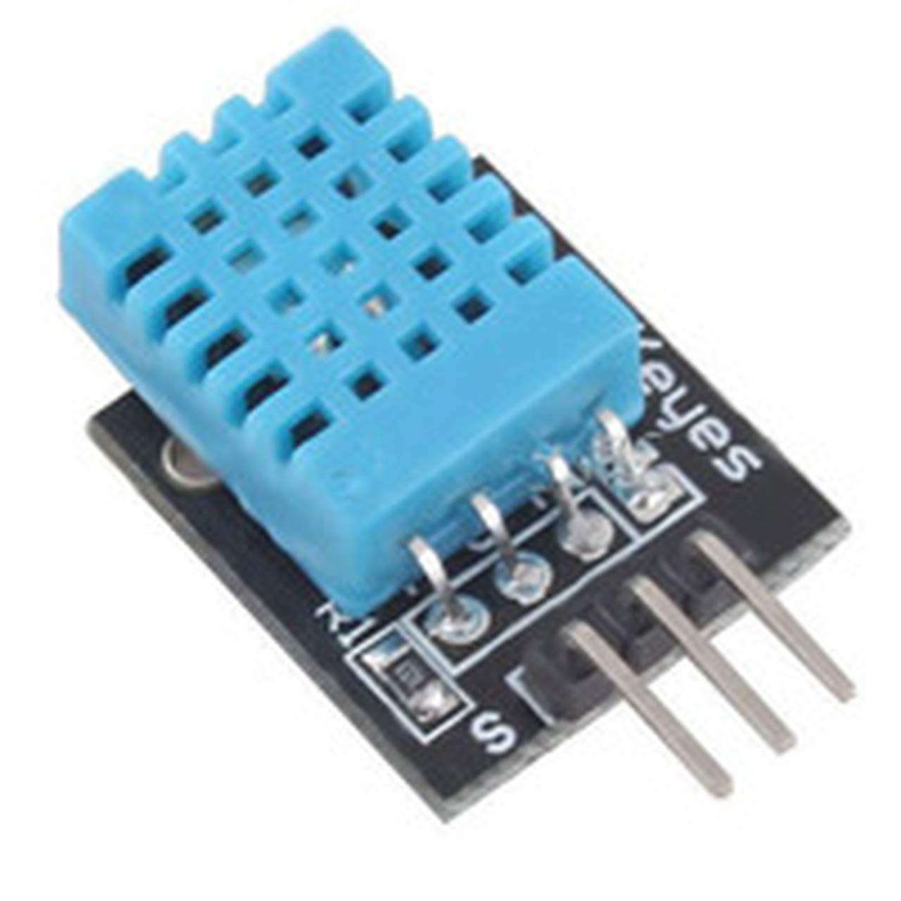
Technical Details
Low cost
3 to 5V power and I/O
2.5mA max current use during conversion (while requesting data)
Good for 20-80% humidity readings with 5% accuracy
Good for 0-50°C temperature readings ±2°C accuracy
No more than 1 Hz sampling rate (once every second)
Body size 15.5mm x 12mm x 5.5mm
4 pins with 0.1" spacing
Source: adafruit.com
I am going to use this sensor as the input device which will collect tha data of the room temperature and humidity and will drive the ouput device as required.
Since i did not have any knowledge about the sensors which we are using so i had to go through a lot of video lectures to understand how they work and how they are coded.
I stated with this video and learnt the basics about the usage of the DHT11
Sound Sensor
The second sensor which i amgoing to use is the sound sensor which will measure the sound of the baby. If the baby is crying then the lullaby ttoyy will start moving. The sound used to check the mechiansm is taken from the mobile.
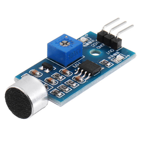
A sound sensor is defined as a module that detects sound waves through its intensity and converting it to electrical signals.Sound detection sensor module for arduino detects whether sound has exceeded a threshold value. Sound is detected via microphone and fed into an LM393 op amp.
Specification of Sound Sensor Module:- Operating voltage 3.3V-5V Outputs digital switching output (high and low level 0 and 1 Operating current (Vcc=5V): 4-8mA Microphone sensitivity (1Khz): 52-48dB Microphone Impedance: 2.2KΩ Microphone Frequency: 16-20Khz Microphone S/N ratio: 54dB Signal output indication Single channel signal output Outputs low level and the signal light when there is soundSource:electronicscomp.com
This video showed me about the connections to make on sound sensor
I have designed a board which has sound sensor and dht11 space in it. I had tested both the sensors on the arduino board and the values weere seen on the serial monitor as well. Butt when i tested on my designed PCB the values were not seen on the serial monitor. I had then understood the USB tto TTL converttor working. Initially when i desinged my board, i did nott have the FTDI pins on my board and i was nott able ttto see the values of the sensors but then my PCB also burnt off so i designed a new PCB with FTDI on it and when i tested it i could see he vlaues on the serial montor.
The reason for my PCB was burnt was that the legs of the transistors were touching each other and when i powered it up with 12 volt supply , it burnt off. I took care of that when i soldered my PCB the next time.
I have explained about the debugging of the PCB which i did a ot of times in the final project page. You can see this page.
The design of the board and the code on which i ran the board can be found on this page.
The program which i ran on this board is the same which ran for my final project. To see the program you can visit this page.
.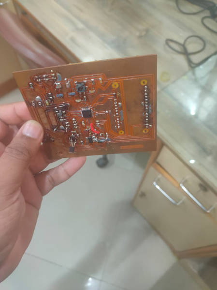
This PCB did not have the FTDI on it which prompted me to design with FTDI on it. I also did not know how to connect USB to TTL converot to it but then i read on the net and found that you just need to connect the RX, Tx and GND pin with the FTDI and then select the COM PORT and the values are visible on the serial monitor.
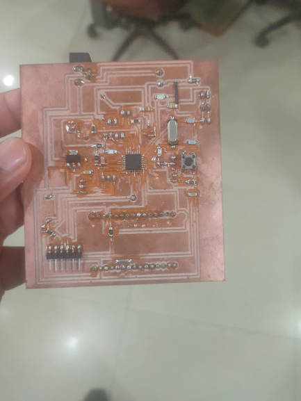
As you can see in the picture that the new PCB designed is having FTDI while the older one is not having that.
The values on the monitor were not clear so i have uploaded one new video where the values are easily seen.
The integer values which you are seeing is the value of the temperature and then the value of the humidity. The values which was initially showing on the monitor change dto 605 which shows that the temperature is changed to 60 and humidity is reduced to 5 after the application of the Hot air blower on to the sensor.
The temperature unit is in degree celcius and the humidity is relative humidity which is described in percentage.
So in this scenerio the value is 60 degree celcius and the relative humidity is 5 percent.
Group Assignment
Measuring Analog Signal:
We measured the analog signal by connecting both the probe of oscilloscope to Gnd and Vcc pin of dc motor and rotated the shaft manually. The motor is generally consisdered as the output device but if i give rotation o motor manually then an induced voltage can be seen on the oscilloscope. Since the construction of the motor and generator are similar so we used motor as the input device.
Measuring Digital Signal:
We uploaded Blink code on the UNO board and we observed the pulse signal.Above are the results for the same.
General Mistakes
The pin configuration of the Dht 11 and sound sensor is different. While designing the PCB it is rewuired that you give the pins from the microcontroller in the same order which is there with your input device. For example Dht11 has VCC then Signal Pin and then GND But for the sound sensor it is completely different.
Since we developed our final Project before doing assignments so we had very limited knowledge and experience about the instruments like USB to TTL converot. So the mistake i did was that i did not give any pins for USB to TTL convertor for Serial Communication and i could not see the results coming and just because of this i had to design a new PCB and but it was a good experience of using the Convertor.
Conclusion
It is always reccommended that you do some experiments with the arduino Board from there you will get confidence and with that confidence you can go to build your PVB for the project. It was a good experience working with input devices.