Weekly Task
Group assignment
Campare the performance and development work flows for other architectures
Individual assignment
- read a microcontroller data sheet
- program your board to do something, with as many different programming languages
and programming environments as possible
What is Datasheet
It is a document that summarizes the performance, technical and software characteristics in enough detail that anyone can integrate the component into a system. It usually made by the component manufacturer.An electronic datasheet specifies characteristics in a formal structure that allows the information to be processed by a machine. Such machine readable descriptions can facilitate information retrieval, display, design, testing, interfacing, verification, and system discovery.

Reading Datasheet
For learning Microcontroller I read datasheet of Attiny44.Firstly I downloaded datatsheet is HERE
I started reading the "Micro-controller Datasheet" to get a general idea about the Micro-controller and its structure.The attiny 44A is an IC with 14 pins.
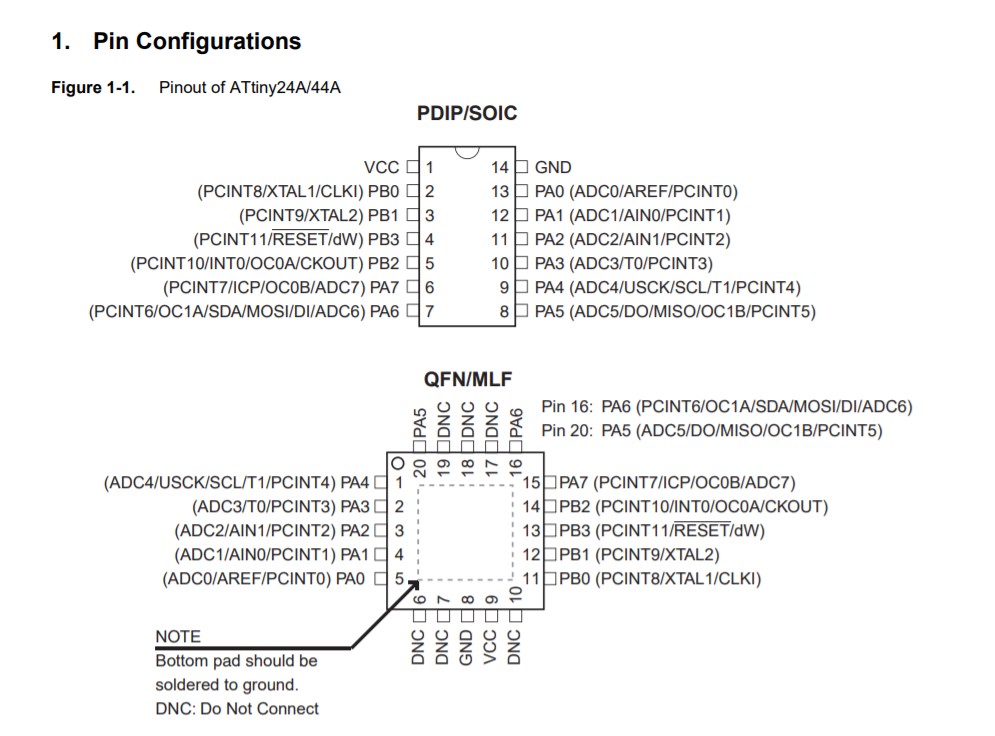
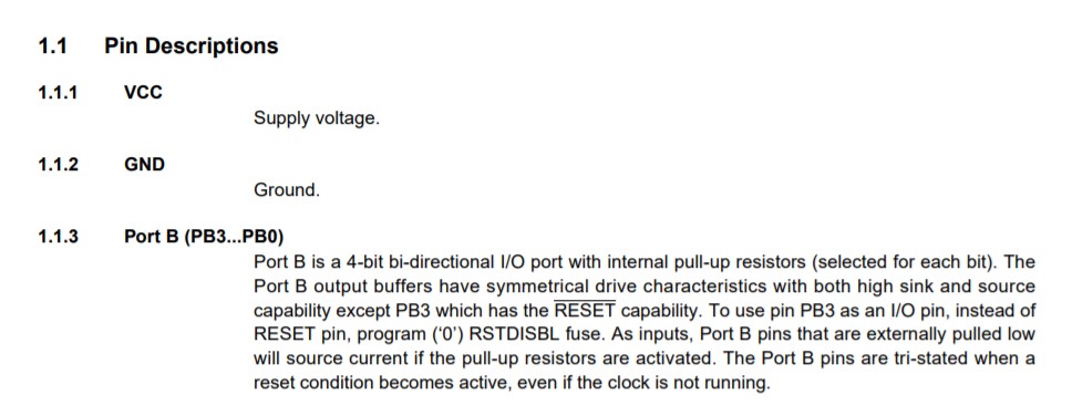
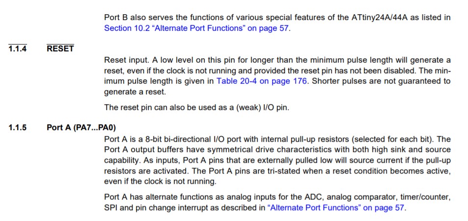
Pin description
ATtiny44A are low-power CMOS 8-bit micro-controllers based on the AVR (controller family) enhanced RISC architecture.(reduce instruction set)
Attiny44A contains three General Purpose I/O Registers. These registers can be used for storing any information, and they are particularly useful for storing global variables. All 32 registers are directly connected to the Arithmetic Logic Unit (ALU), allowing two independent registers to be accessed in one single instruction executed in one clock cycle.
A stack pointer is a small register that stores the address of the last program request in a Stack
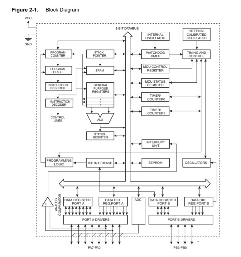
The main function of the CPU core is to ensure correct program execution. The CPU must therefore be able to access memories, perform calculations, control peripherals, and handle interrupts.
The AVR uses a Harvard architecture with separate memories and buses for program and data.
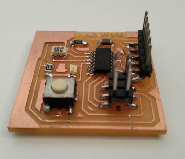
Programming on Hello board
In electronic design week,I made a hello board and add two extra component, one button and one led light.and also program it, which is given by Neil.In this assignment I make c program and upload on board.
For the programming I have used Arduino uno.Arduino is an open-source electronics platform based on easy to use hardware and software and also user friendly.I downloaded Arduino ARDUINO IDE
we don't have Attiny 44 as in the boards list in arduino IDE, we need to add it.
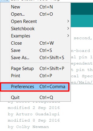
1.Open the preferences dialog in the Arduino software.
2.I go HIGH-LOW-TECH site. then copy the below link from here.
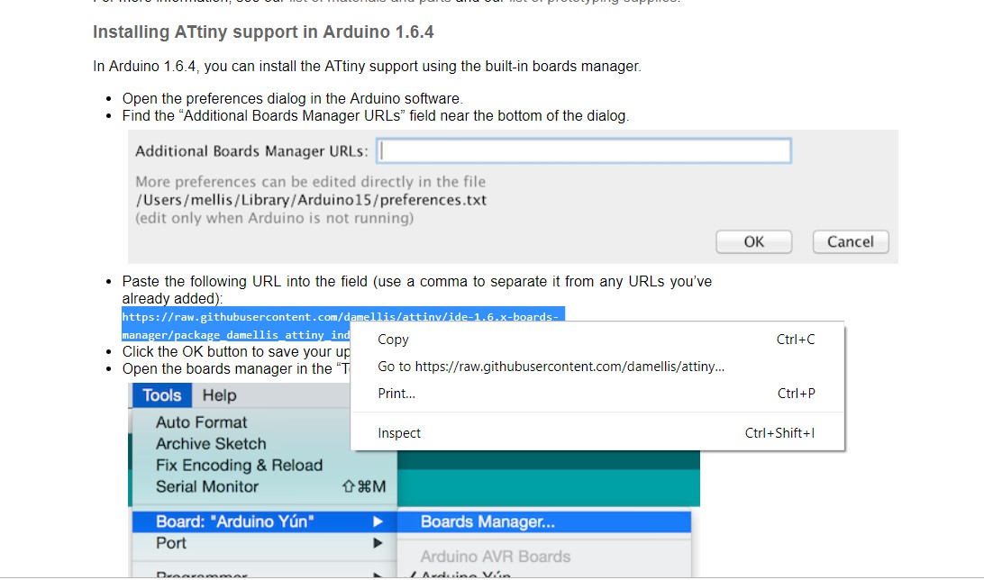
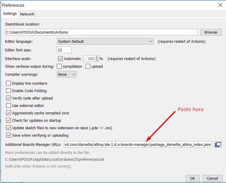
3.Paste the following URL(Attiny44) into the field.-
https://raw.githubusercontent.com/damellis/attiny/ide-1.6.x-boards-manager/package_damellis_attiny_index.json
4.Click the OK button to save your updated preferences.
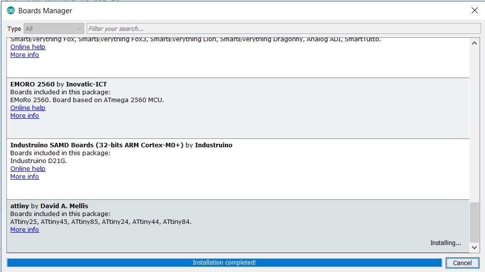
5.For adding Attiny Library.Open the boards manager in the “Tools -> Board” menu.at the bottom of Board manager I saw entry of the Attiny.Click the install button.
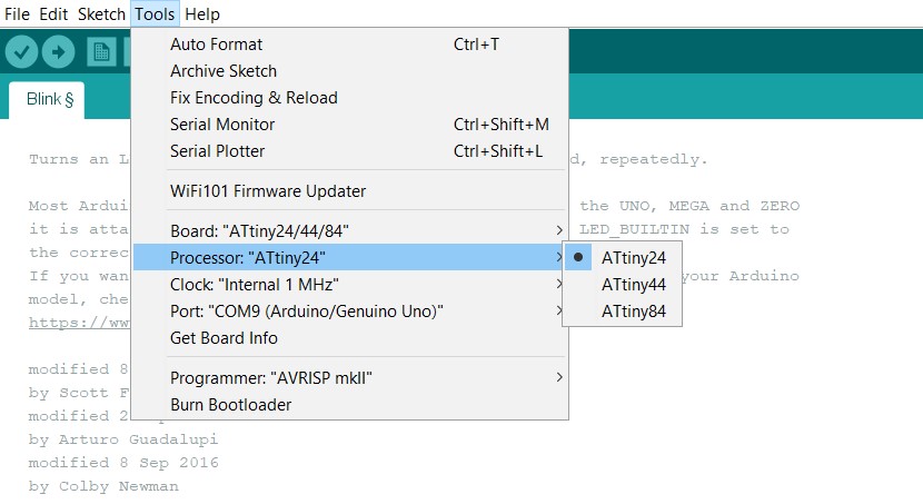
6.Then select the board the tool tab.
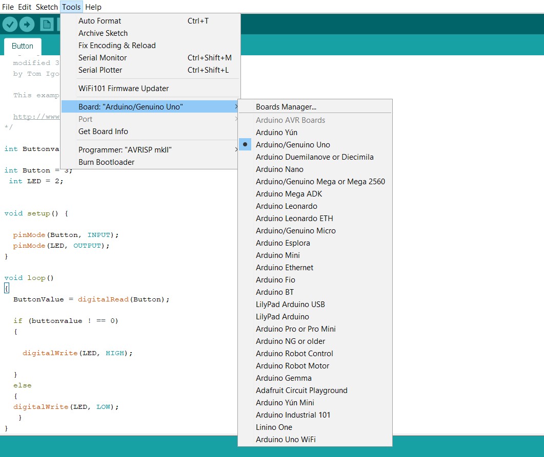
7.I checked Library.Select which Attiny Processor. (Attiny 44)
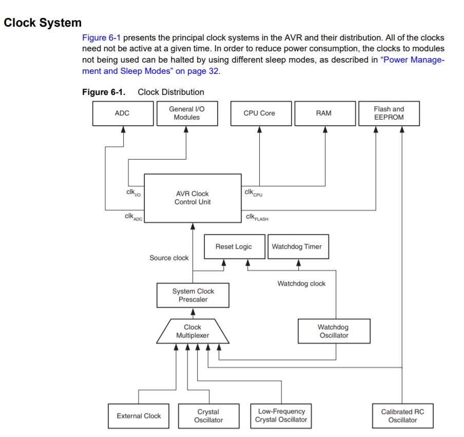
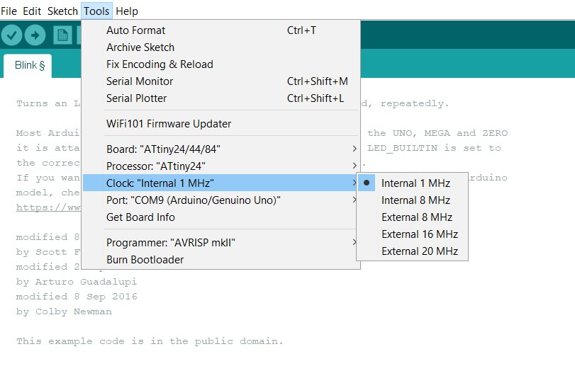
8.Select the Clock (Crystal SMD Frequency, 20 Mhz in this case)
Electronic This is new to me and I am learning it, while designing a hello board.I put it on the pin reset button. So my LED blinked when i pressed my Reset button.that time I was sure the soldering and connectivity was okay if the reset button was pressurized. But I wanted to blink the led countinue. For this I used the external LED using broadband, and it got the work done.
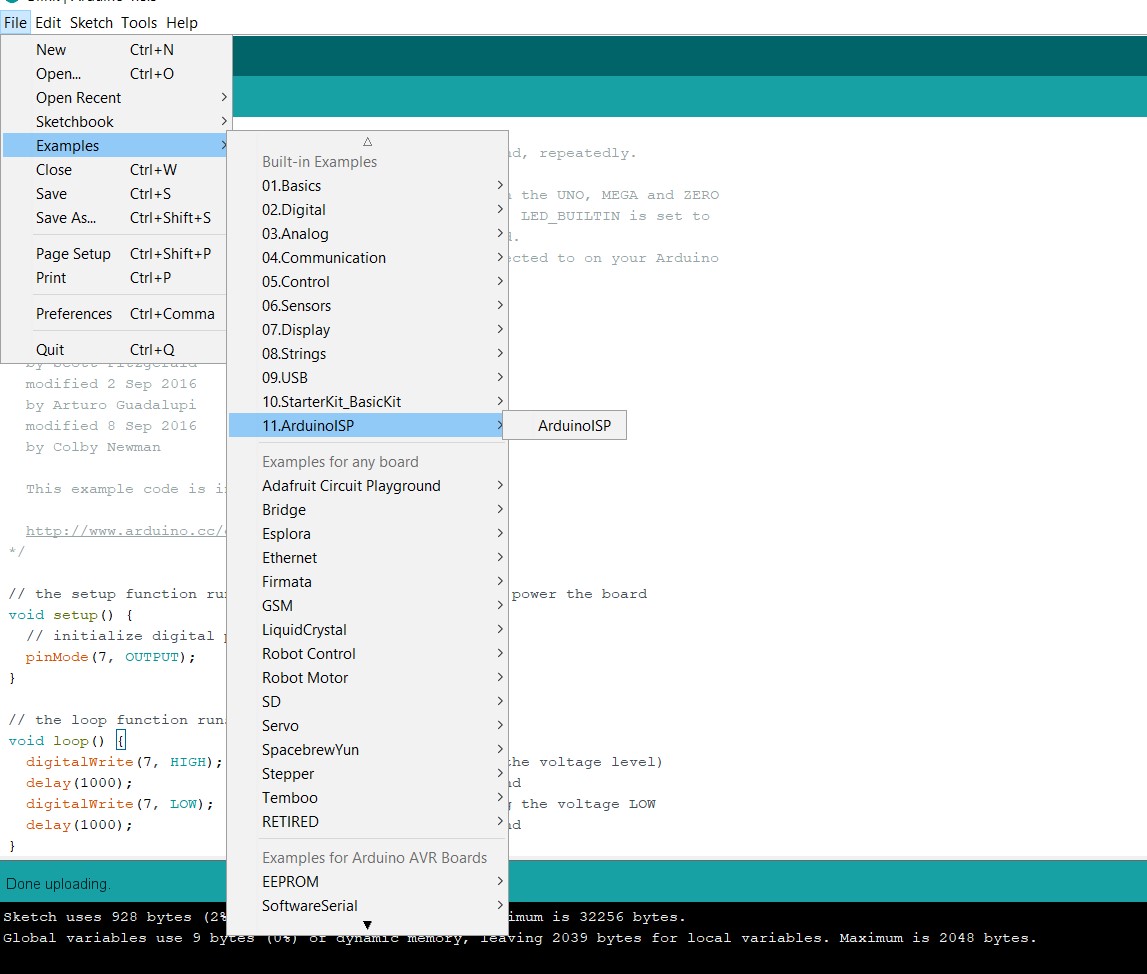
Firstly I runned my LED blinking program using Arduino as ISP.I test my board on Arduino
1.I go to Examples and opened ArduinoISPProgram
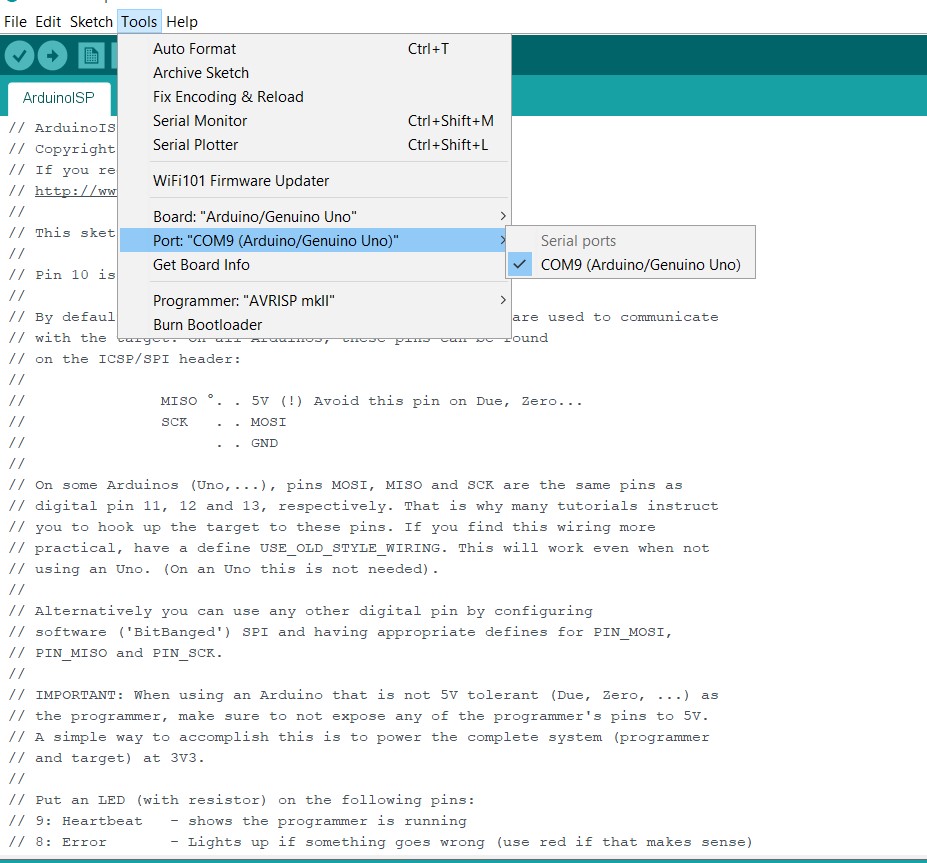
Connected pins as Arduino to hello board as follow:
2.Selected port
For burning program in Arduino I clicked on Burn Bootloader.
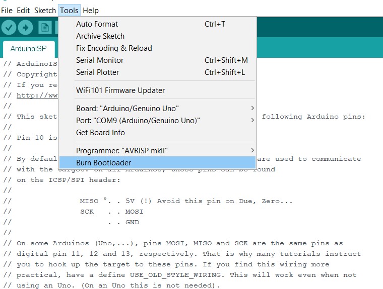
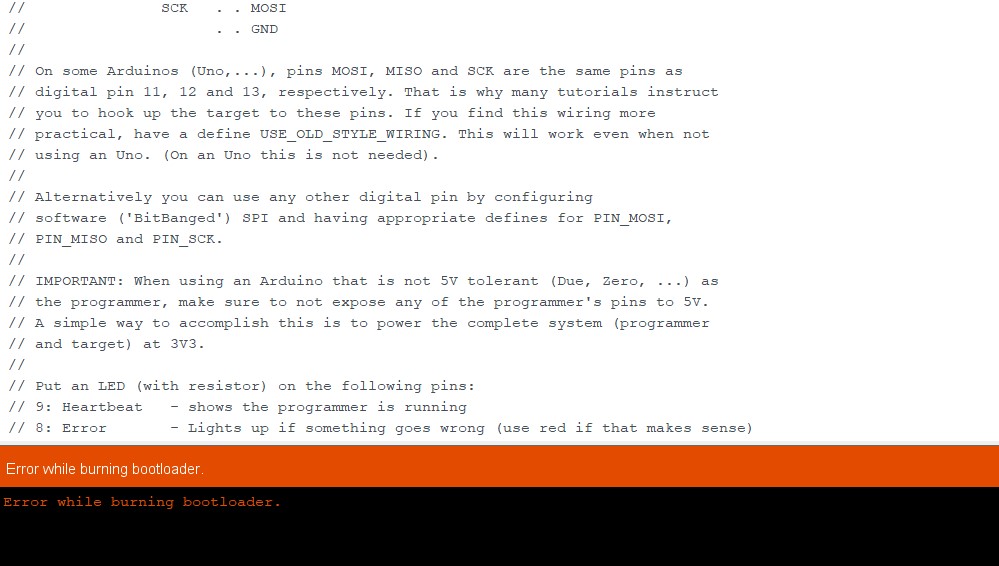
After burning program. I got error. that time I checked my all connection and again.
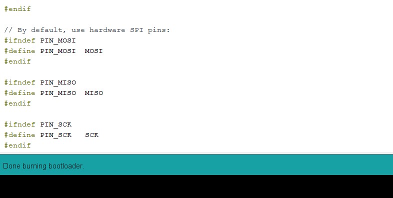
Finally......Done burning Bootloader.
Here I got output was when I pressed my reset button arduino LED also reset.that time I don't understand what I do.
Then I used my FabISP programmer for programming on hello board.First I selected some option like
Firstly I burn the program on FabISP. then upload simple LED blinking program by default in Arduino.then I got error.
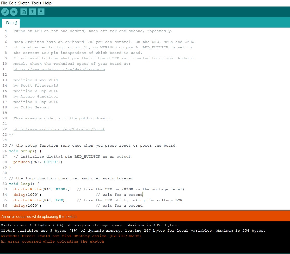
Two days I got a single error that my FabISP was not detecting properly. then I solder my FabISP again.then its detected.
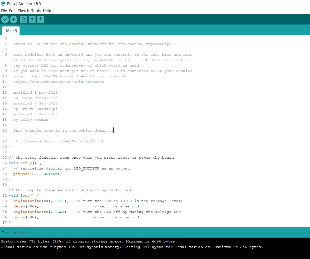
I used this program which are given in Arduino.I defined my IC Pin PA1 which is connected to LED.
void setup() {pinMode(PA1, OUTPUT);
}
void loop() {
digitalWrite(PA1, HIGH);
delay(1000);
digitalWrite(PA1, LOW);
delay(1000);
}
Arduino is very easy language for programming.but,In this week write a C Program and upload it.
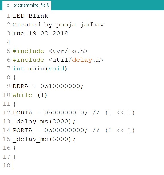
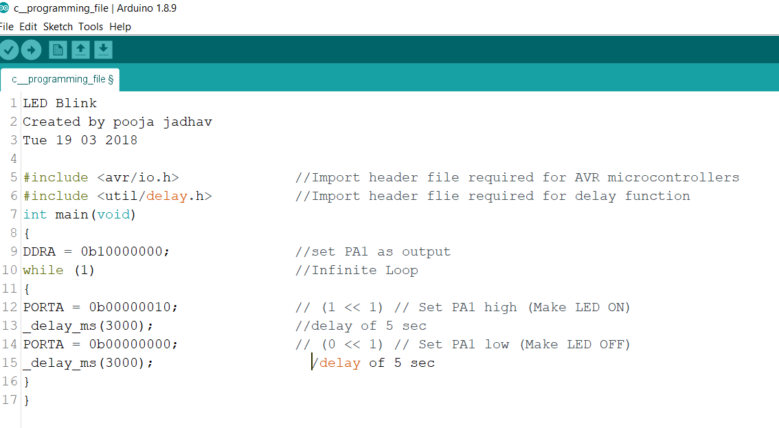
This time we also arranged guest lecture of Previous fab academy student Mr.Rohan Rege on Embedded C Programming.that time we understood how to write program in Embedded C and how to use this.Then I made simple LED blinking in C file.
In my Hello World Board, I have connected LED to PIN6 i.e. PA7. So first step is to define PA7 as digital Output.
The Attiny 44 has 2 sets of these (PA and PB). For port A (PA0-PA7) we use the DDRA command.
For the C programming I also used Arduino IDE.
After writing I made connections and for this I used my FAB ISP to program my hello-world board.
I directly uploaded C program in Arduino.Firstly I compiling the program I upload on Board.Its working.
            /*

            * led_blink.c

            *

            * Pooja Jadhav

            *

            */


            #define F_CPU 20000000                //Define clcok speed as 20Mhz

            #include <avr/io.h>             //Import header file required for AVR microcontrollers

            #include <util/delay.h>         //Import header flie required for delay function

            int main(void)

            {

            DDRA = 0b10000000;                //set PA7 as output

            while (1)                         //Infinite Loop

            {

            PORTA |= (1<<7);        // Set PA7 high (Make LED ON)

            _delay_ms(5000);              //delay of 5 sec

            PORTA &= ~(1<<7);       // Set PA7 low (Make LED OFF)

            _delay_ms(5000);              //delay of 5 sec

            }

            }
Successfully run the program....
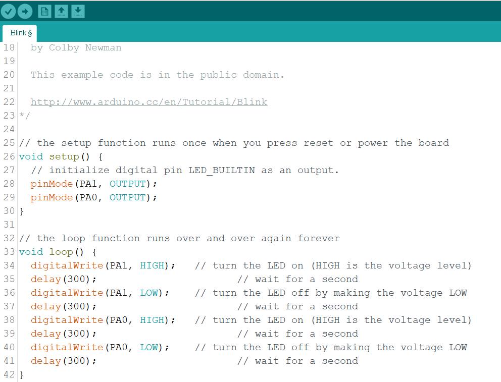
I add a one more LED.and add pinout in program.
Uses of Datasheet?
From datasheet got a pin diagram of Atmega328p.I understand about their configuration.when I design my PCB Board I refer datasheet and pin diagram.my connection is properly connected to IC.i understood about connection.
Group Assignment
In Group Assignment is compare the performance and development workflows for other architectures.we have two architectures first one is Arduino and second is Raspberry Pi Architecture.we Know Arduino programming very well.
As I read on google that time I understood difference between Microprocessors and Microcontroller.Camparision
we had decided to explore Raspberry pi, it's architecture, configuration and coding it through python
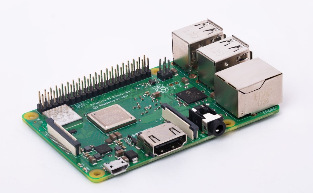
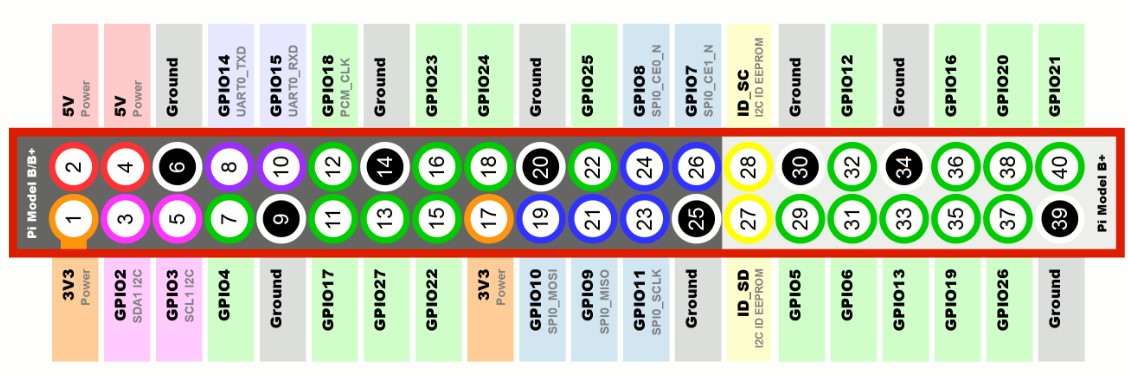
This is pin diagram of Raspberry pi.we connect the cables using this diagram
Our Instructor Mr.Suhas Labade introduced raspberry pi in front of us.its work and other stuff.raspberry pi is working on python code.suhas sir shows lED blinking program the python code
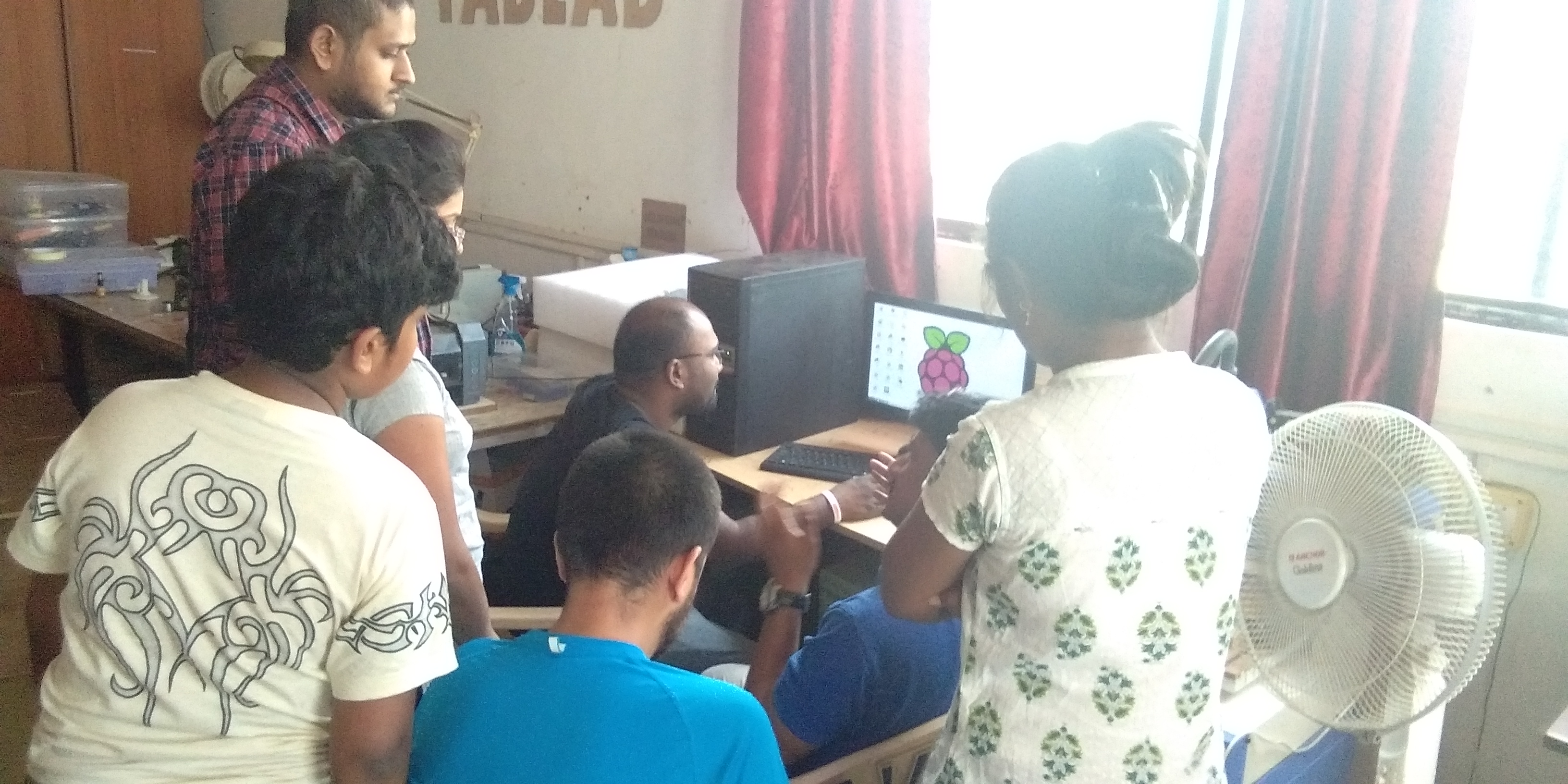
Setup of our group assignment
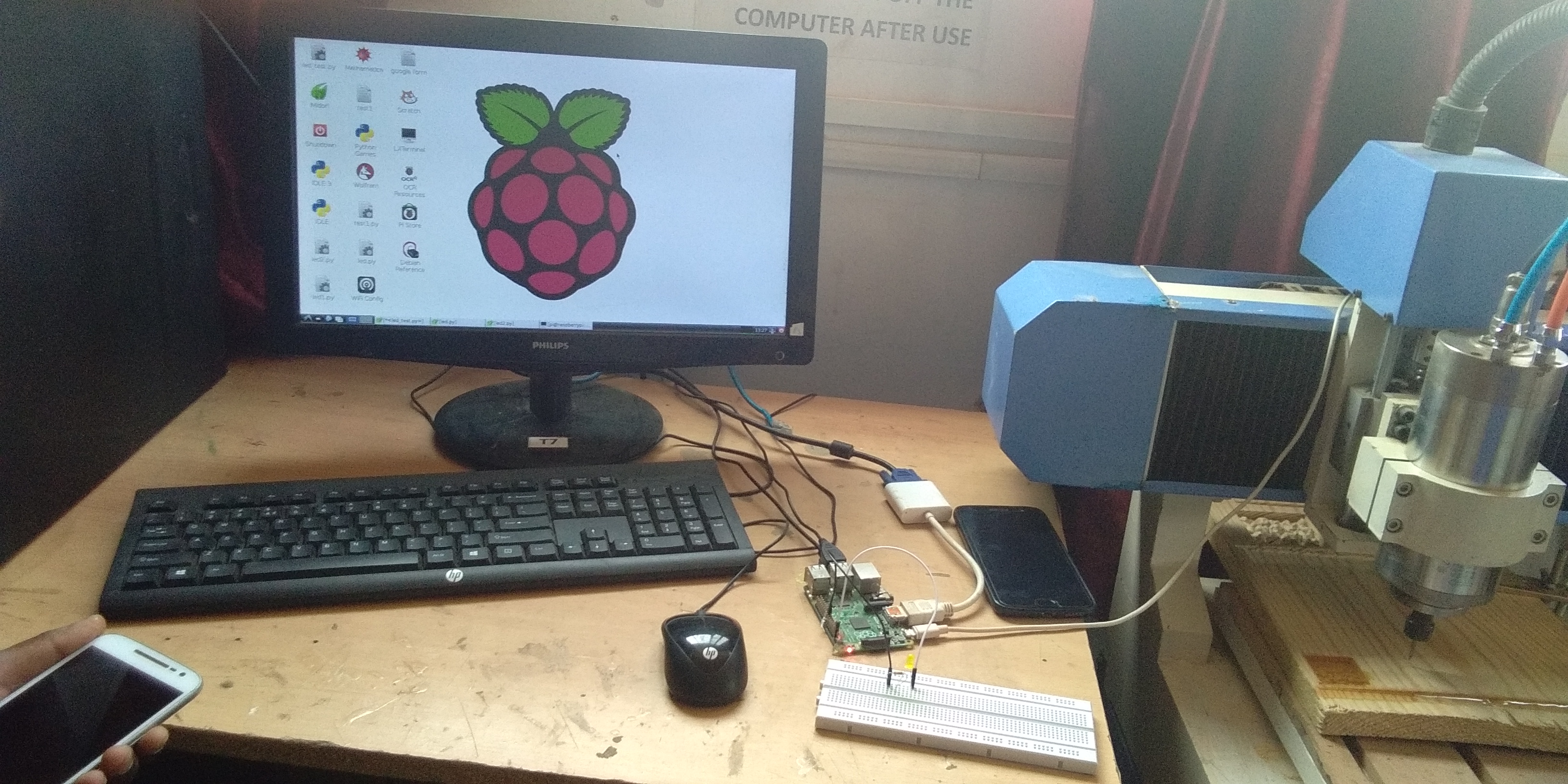
After we decied doing one more program.so,we decided LED ON/OFF program using switch
this is the python code..I decided to write a simple code in python to blink LEDS with description.
import GPIO as g #importing the general purpose input/output pin control library and renaming it as 'g'import time #importing the time libraryg.setmode(g.BCM) #setting the pin layout based on BCM rather than normal numberingg.setup(18 , g.out) #defining the output pinprint "led On" #Printing the LED ON in terminalg.output(18 , g.HIGH) #Turning the output HIGHtime.sleep(1) #Sleeping for 1sprint "led Off" #Printing led off on screeng.output(18 , g.LOW) #turning the output LOWThe above program is LED ON/OFF program using switch
            import RPi.GPIO as GPIO

            import time


            GPIO.setmode(GPIO.BOARD)

            GPIO.setup(11, GPIO.OUT)

            GPIO.setup(13, GPIO.IN)

            while True:

              input=GPIO.input(13):

                        print input

                        if GPIO.input(13)==0:

                GPIO.output(11, True)

                time.sleep(0.1)

                GPIO.output(11, False)

                time.sleep(0.1)
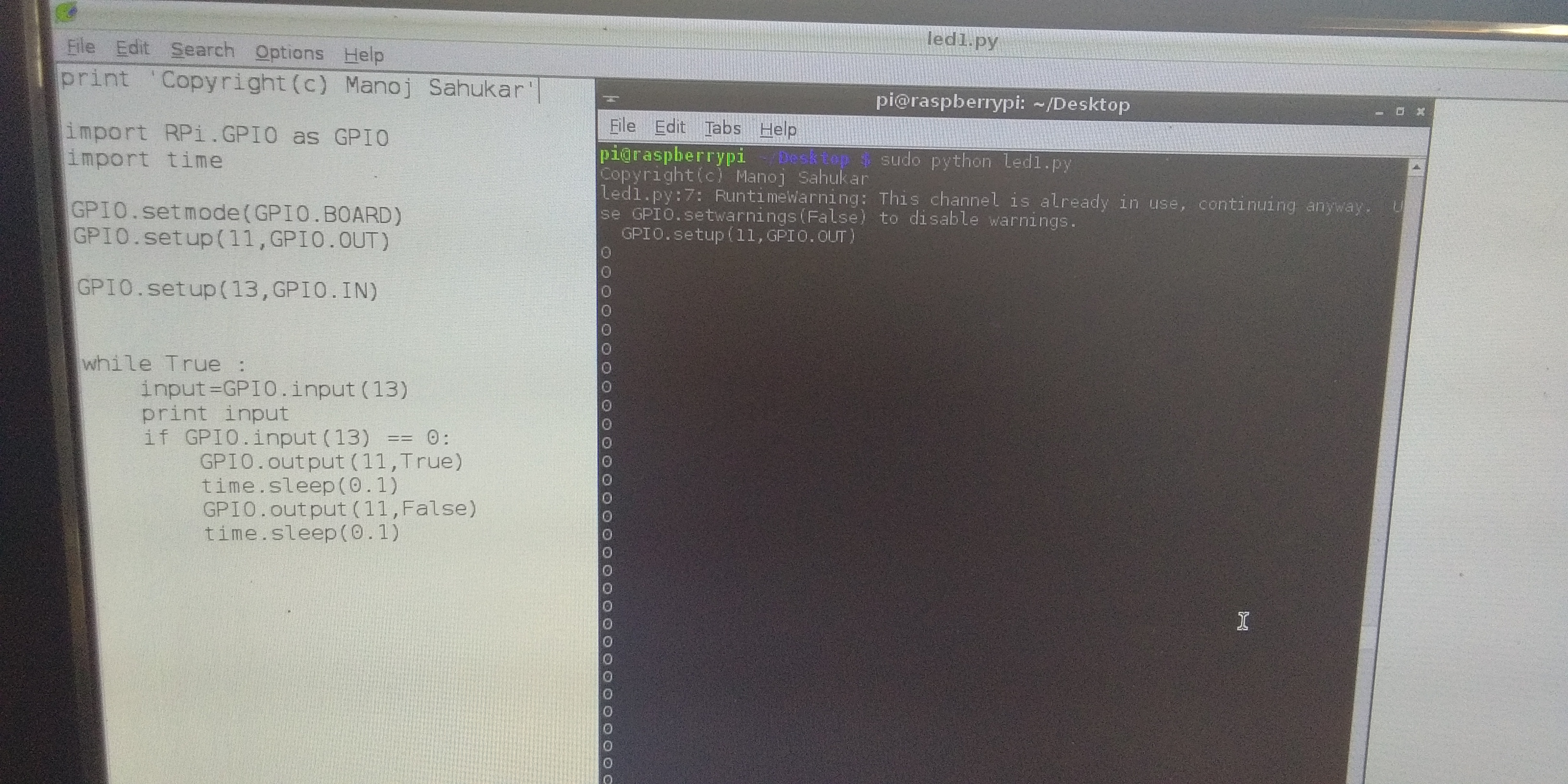
Then we run the program and get the output.
You can Download Original Files HERE.
learning Outcomes
In this assignment I learned new things in programming.I learned Embedded c.I started with arduino and then we are going for raspberry pi in group assignment. I read the datasheet and while writing the code I realized its importance.