Weekly Task
Group assignment:Test the design rules for your 3D printer(s)
Individual assignment:
- 3D scan an object (and optionally print it).
- Design and 3D print an object (small, few cm) that could not be made subtractively
What is ADDITIVE and SUBTRACTIVE Method
ADDITIVE - It is a process of build any object in layer by depositing any material.
SUBTRACTIVE - a process by which 3D objects are constructed by successively cutting material away from a solid block of material.
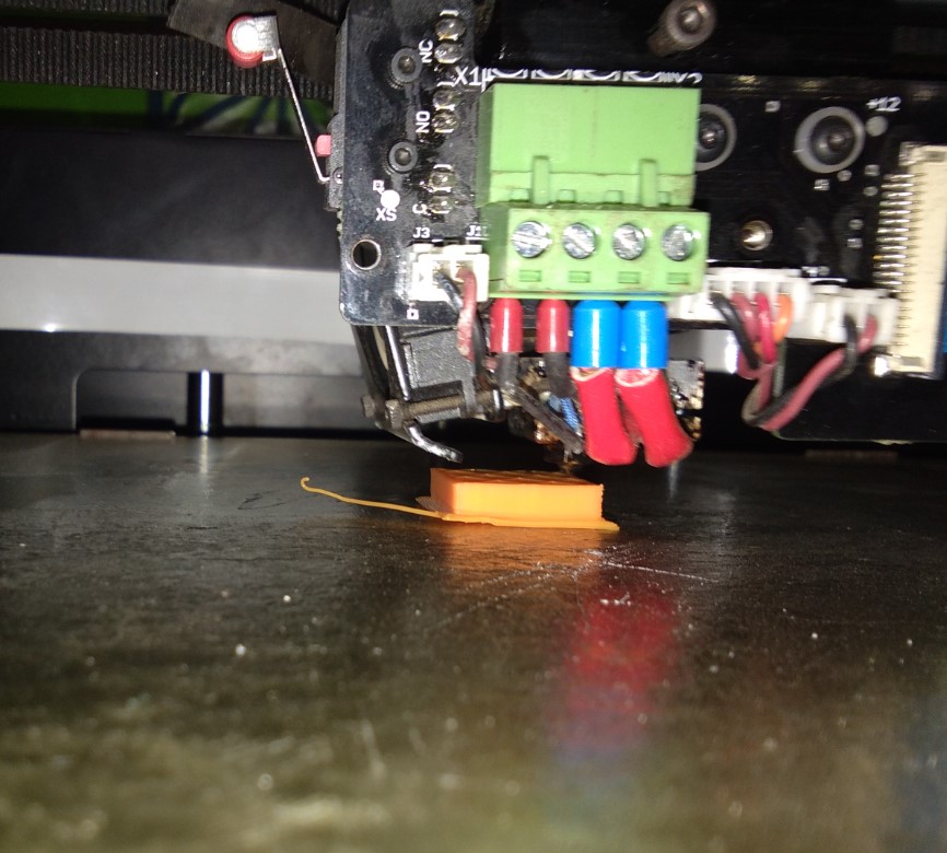
Introduction of Machine
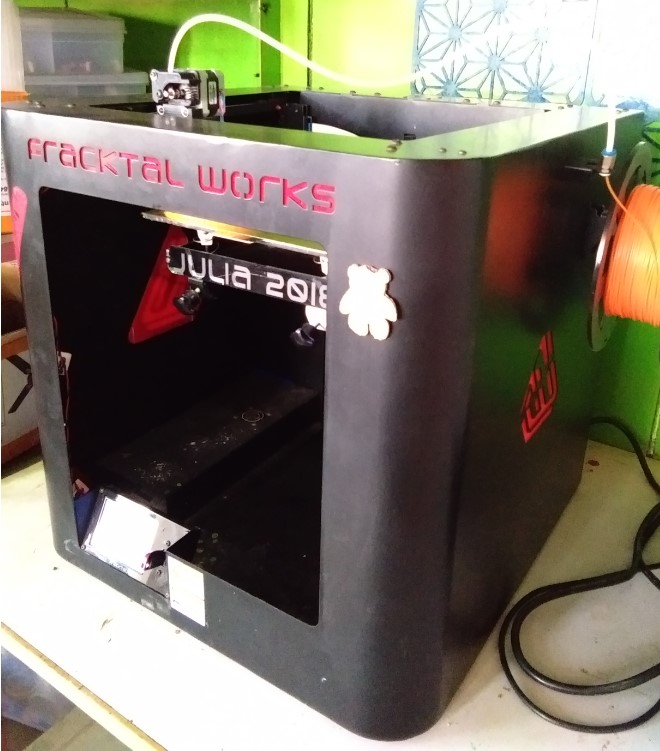
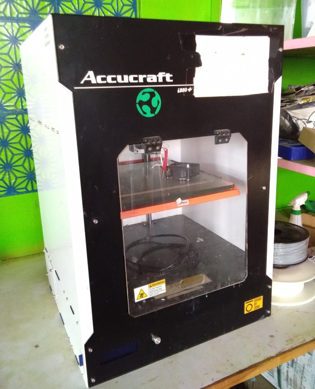
Here we have two 3D printer, one is Accucraft and another is Julia from Fracktal Works. Personally,I had use both machines, but mostly prefer to work with Julia printer. 3D printers is my favourite. It maintain origin on its own and directly follow the gCode and it is easy to control. Here for generating the gCode we use Fracktory 2.0 software.
|
|
We use Julia Printer and fracktal Software for our group assignment which is about designing rules of 3D printers and same for individual assignments.
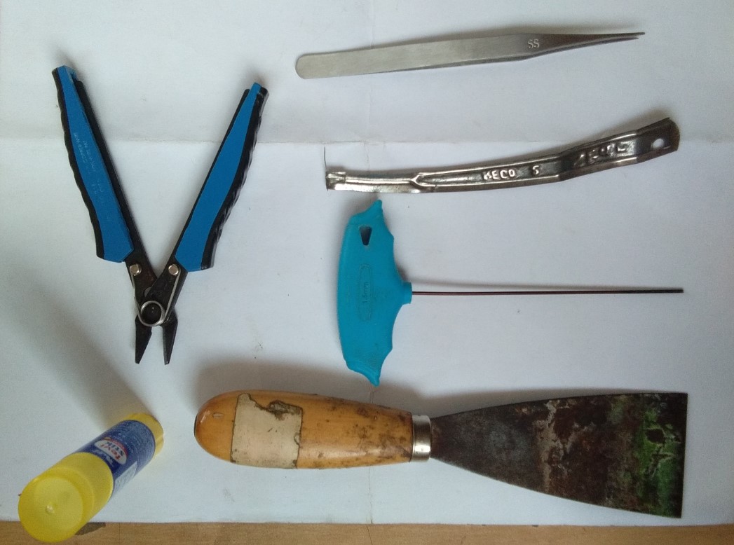
SpecificationWe used these tools when using Julia Printer.
Here Start Group Assignment
In group we started with checking design rules for our selected printer. We first downloaded aTest File from Thingiverse that has several aspects for testing the printing quality of the machine. We used Julia printer with nozzle diameters (0.4mm), but material (PLA), layer height, printing speed and temperature are same like mentioned before. The line width setting is set accordingly to each nozzle (0.4mm).
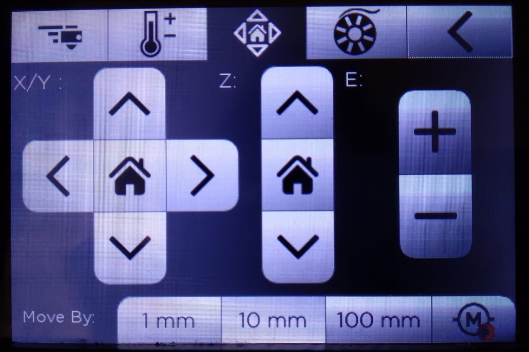
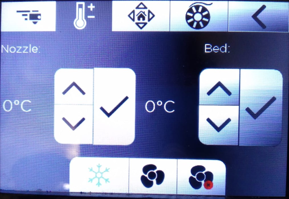
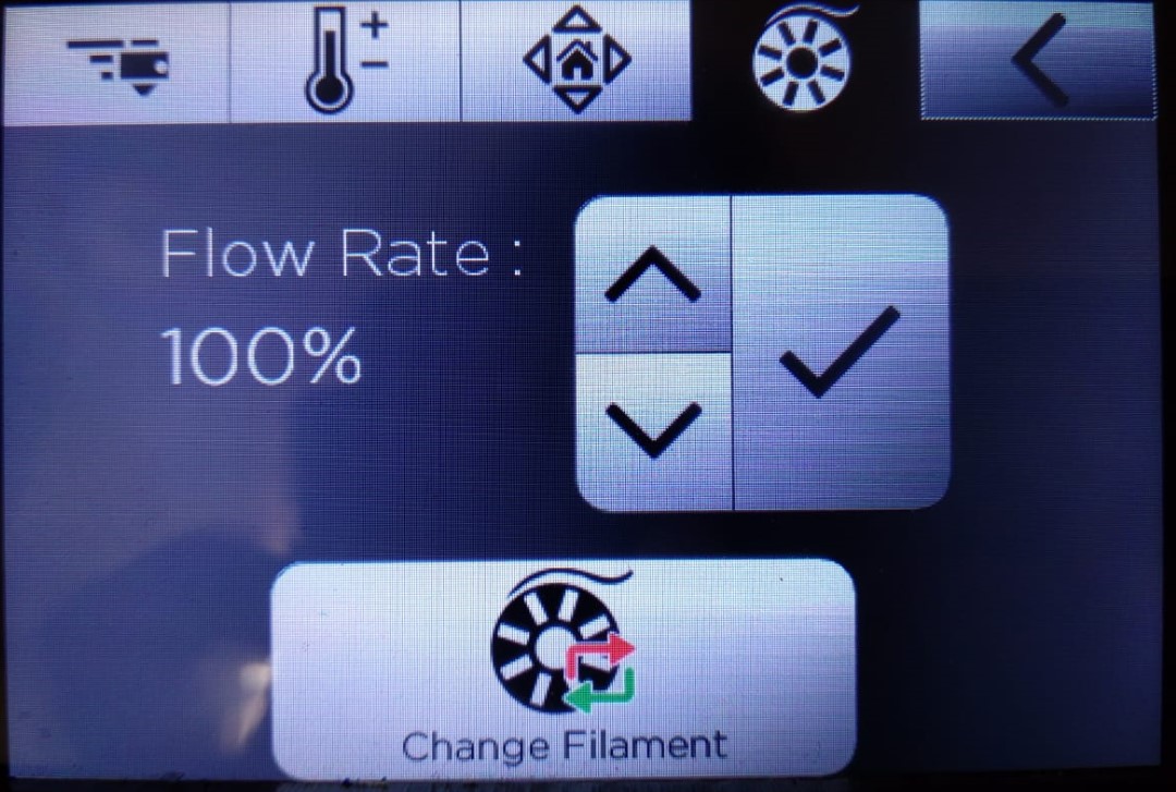
Machine Settings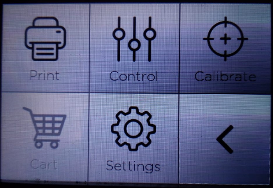
|
|
|
|
In machine setting there is setup option for nozzle X, Y, and Z movement, nozzle and bed temperature, and extruding material.
What we Tested?
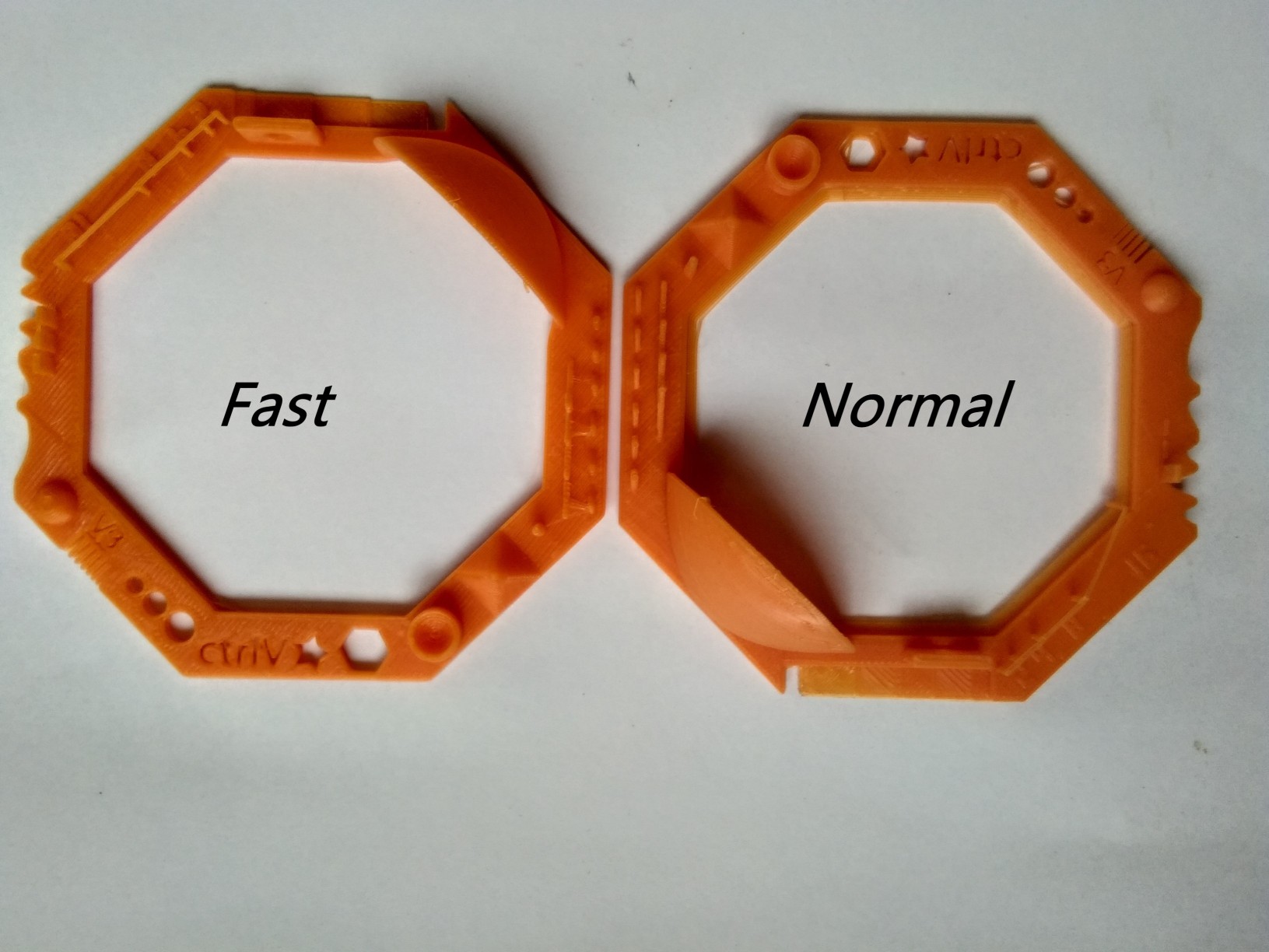
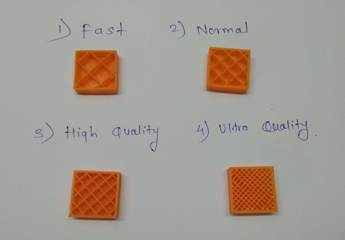
2 different extrusion widths: 0.48mm & 0.4mm Here in next example, We printed two object differ in Quality's. First print is fast print and second print is normal print, both are without support. The result found was that with normal print the print is Okay it still has some little defect in it but with fast print Overhang was not printed well.
|
|
we also tested differnet things.
Content
We created 20mm X 20mm box using OpenSCAD.
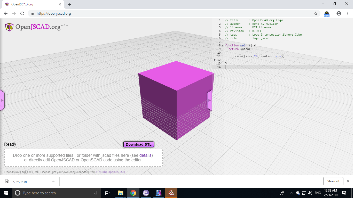
The next we performed the quality test. Gcode for Julia is made using Frackory software, the interface is simple.
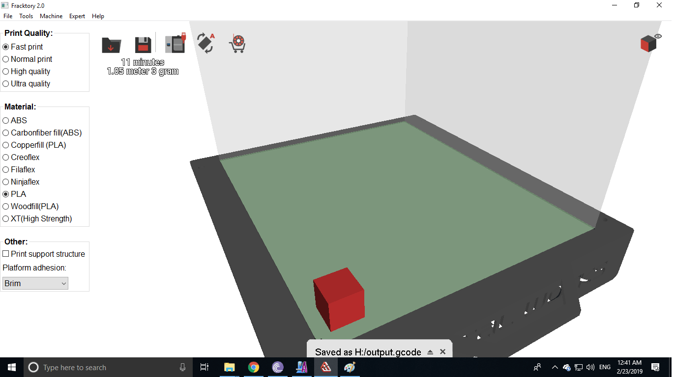
Now Printing....
We check the quality of each boxe. We found infill of each box was different. In Fast print distance are wide and In Ultra print distance are short.
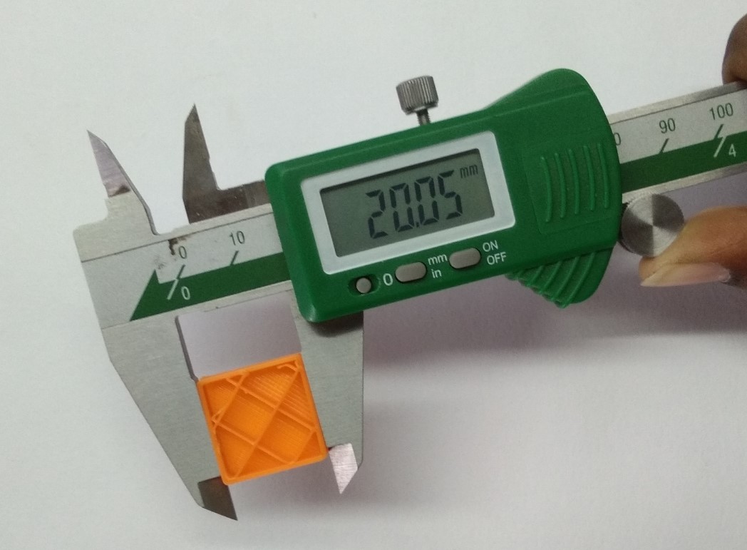
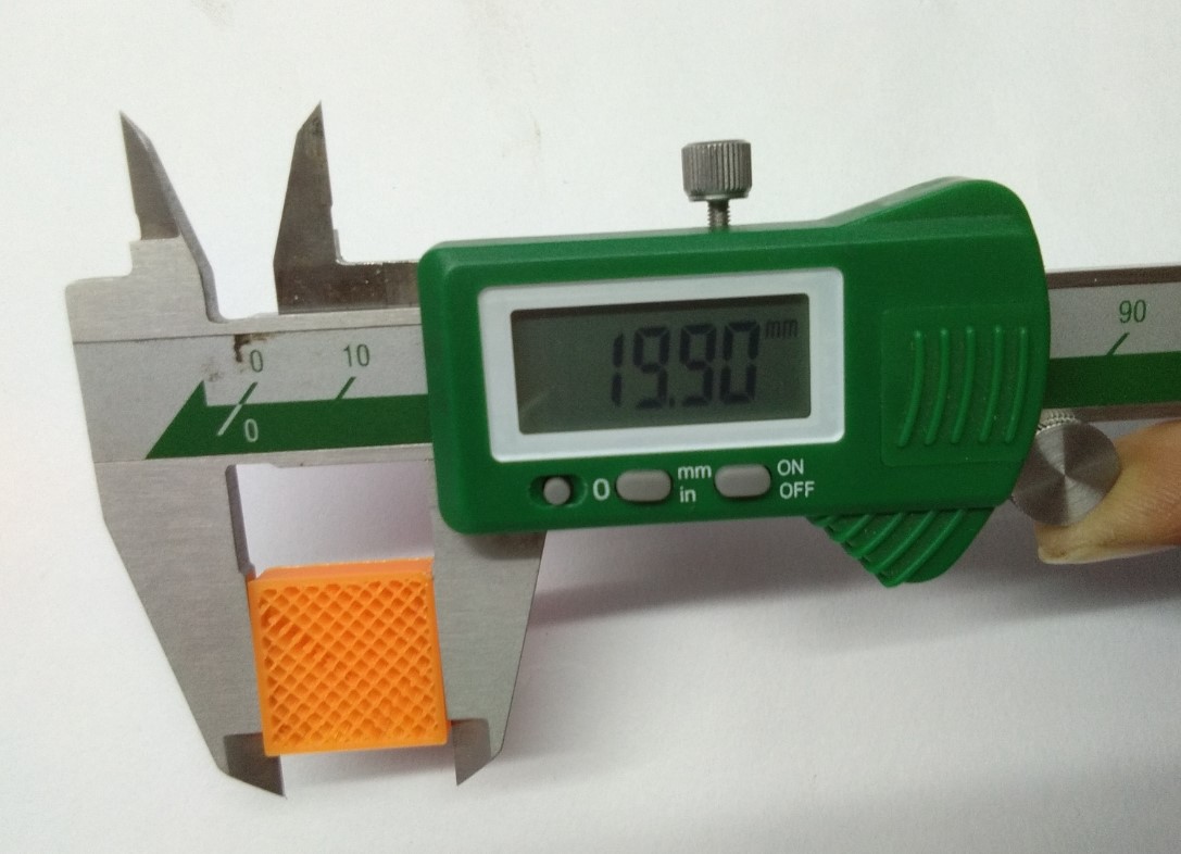
When we further tested the printed part with Vernier, we got different values on each quality like in Fast quality we got scale 20.05mm and in ultra quality we got scale19.90mm .The given scale of box was 20mm X 20mm.
|
|
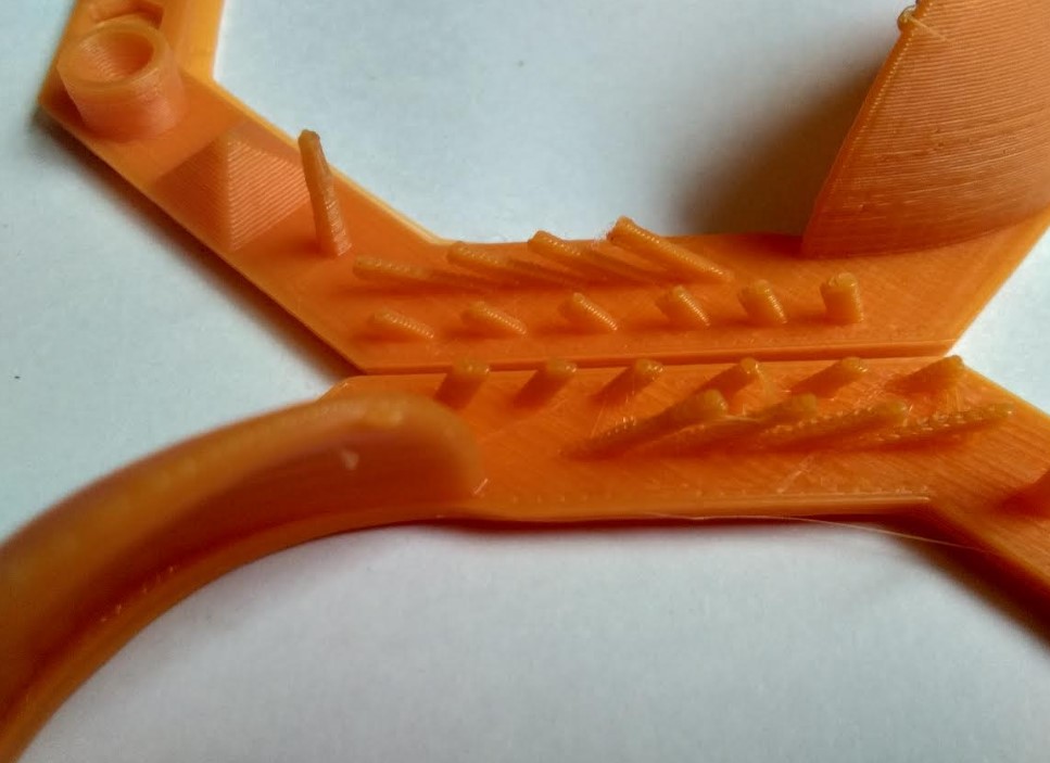
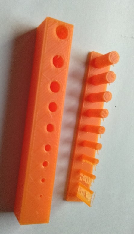
Hole Test IIn this Test we want to see that how the print look and what difference it form with different hole sizes. we begin from creating 0.5mm diameter to 5mm diameter holes. we used Extrude Cut Command for making holes.
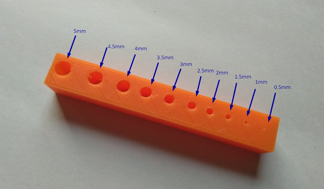
In same design we use Extrude Boss Command to give height. After printing this test file, we found how much the line thickness should be given when designing. In this test we measure each cylinder line it not in proper value. My diameter was 5mm but it gives a value like 4.77mm and one was a thin line of 0.5mm which broken out because of it small Thickness.
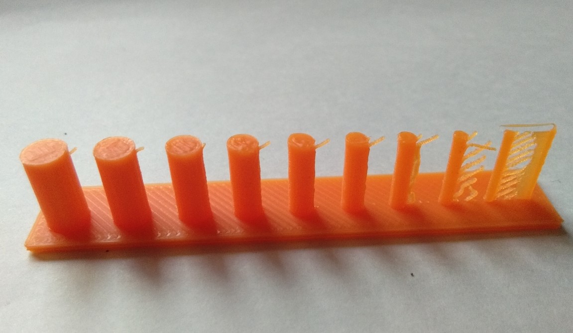
Resolution test we concluded regidity is diretly proposional to thickness.
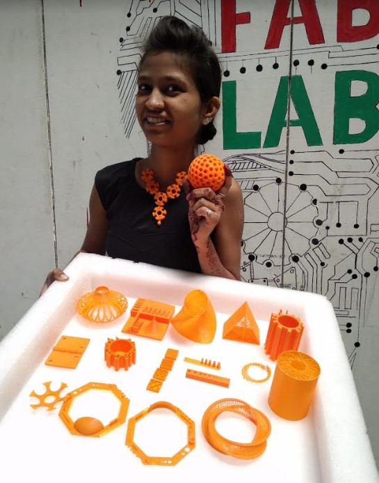
Here,is the all students 3D Printed Parts.
Individual Assignment
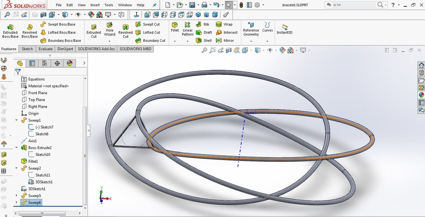
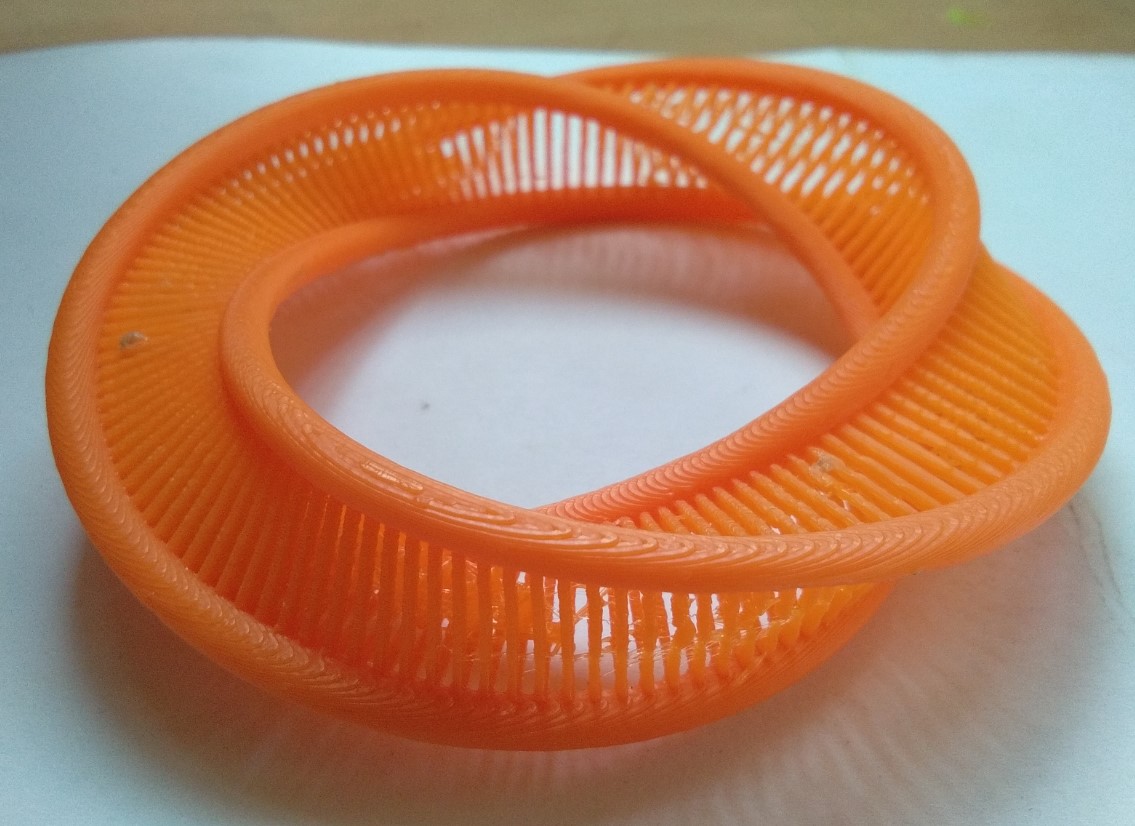
Print an object which is not possible to print substratively Bracelet using Mobius GeometryMobius is a surface with only one side and one boundary. I made many Jewellery designs before but this time I going to make bracelet with this unique idea.For designing I used Solidworks. Steps followed:
1.Select Front Plane then Draw circle which diameter should be size of a hand so it can be easy to wear, here my is 80mm. Exit Sketch Select Top Plane, take Triangle shape and draw on the end point of the circle.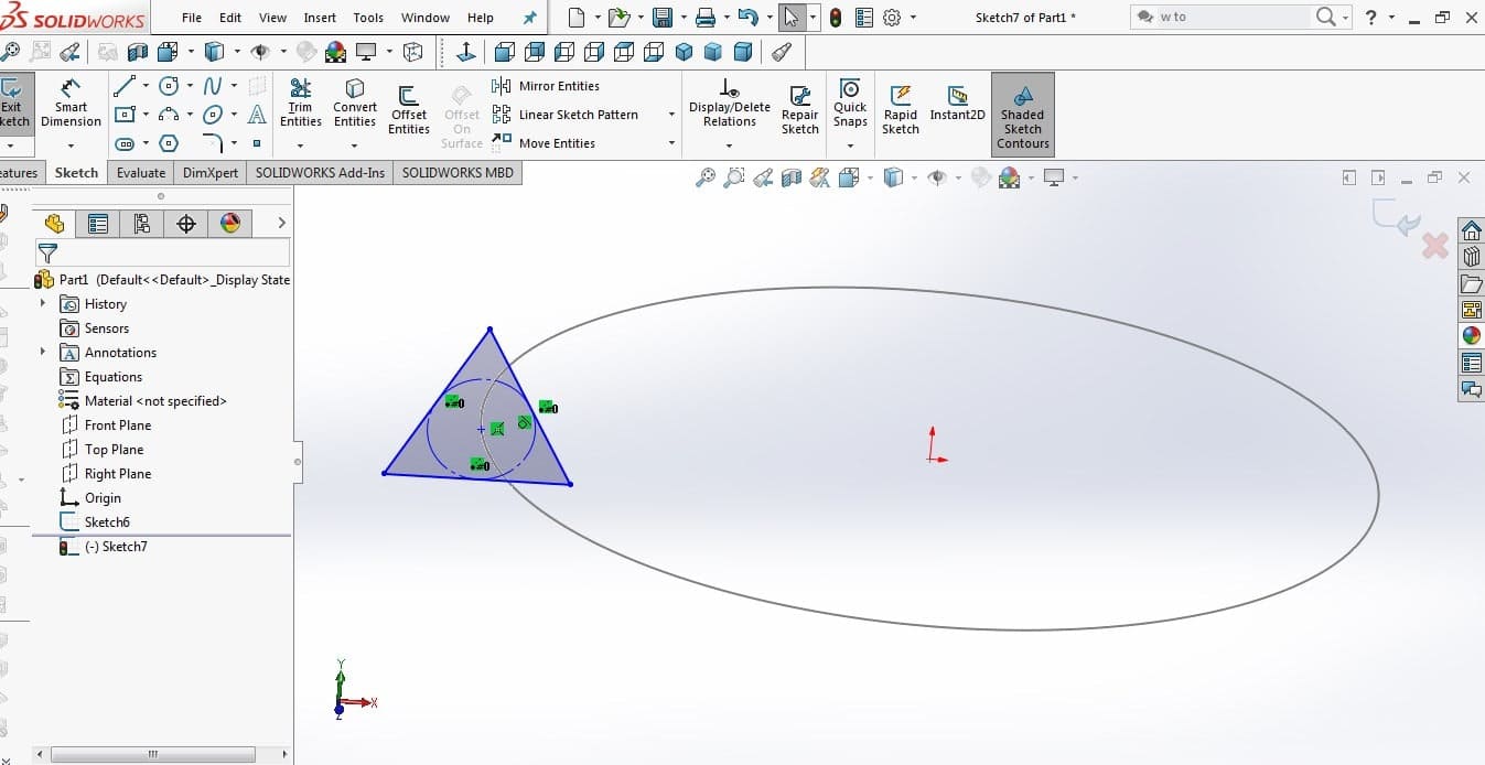
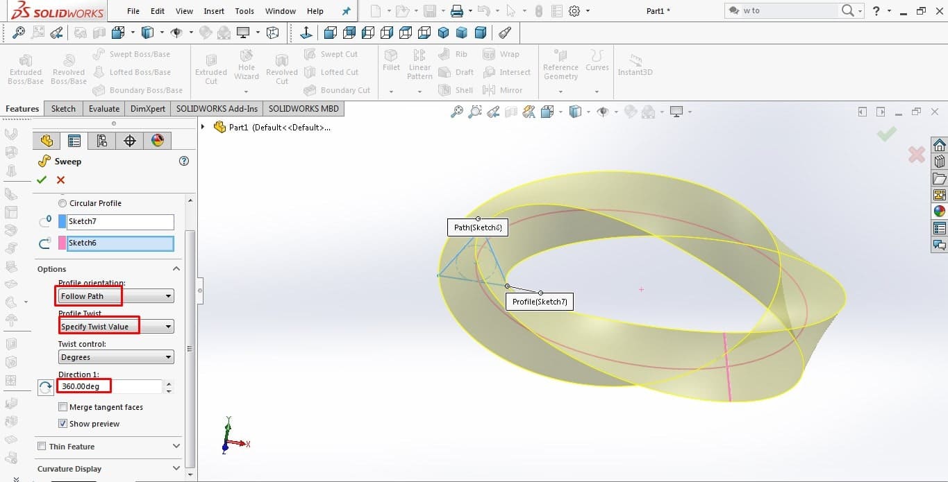
2. Use Swept Boss/Base command and In option in profile orientation scroll to Follow path. Now in profile twist scroll to pecify Twist Value for creating mobius geometric shape and set direction to 360 degree.
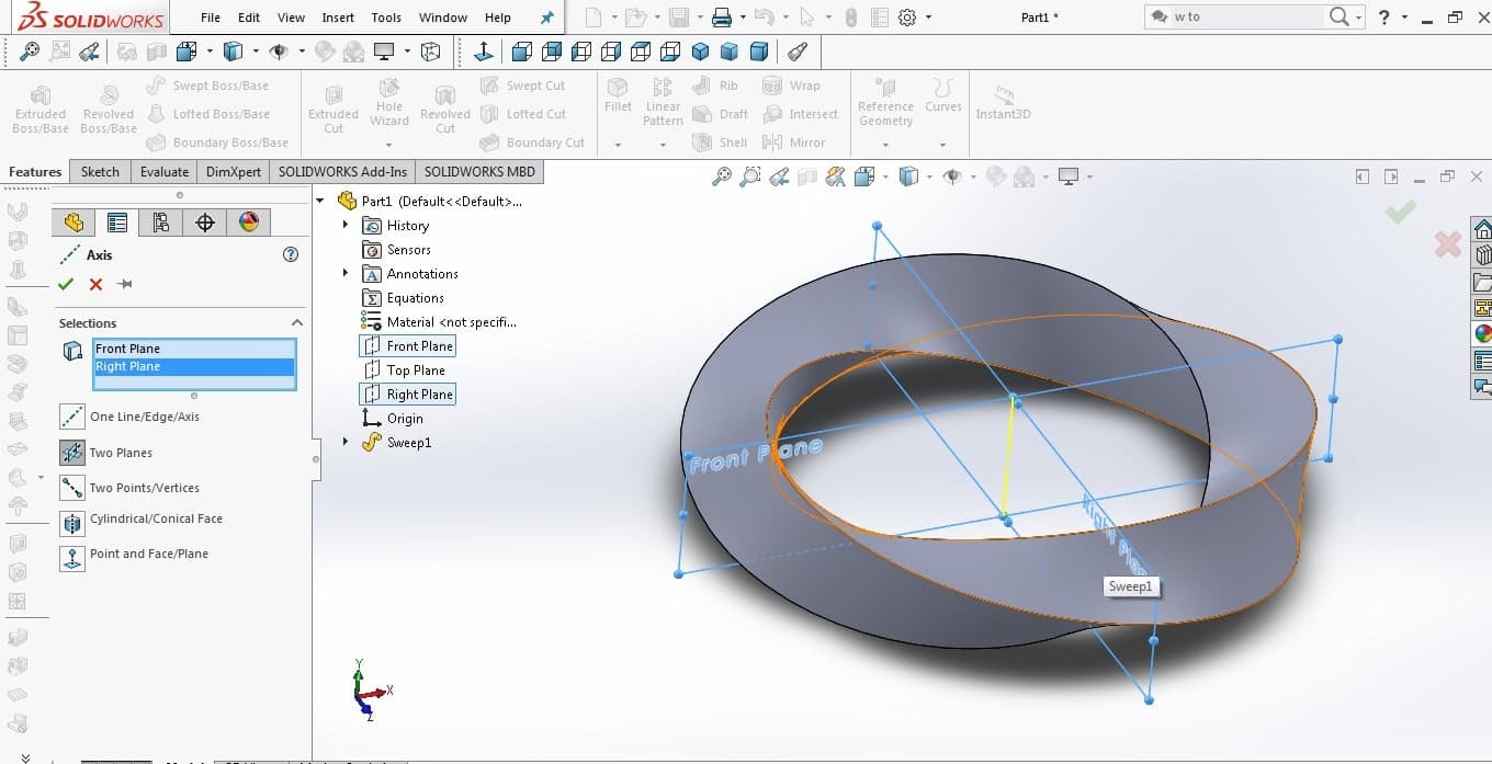
3.Select Front and top plane for giving centre Axis. Then Right click and Hide Edges. last click exit sketch.
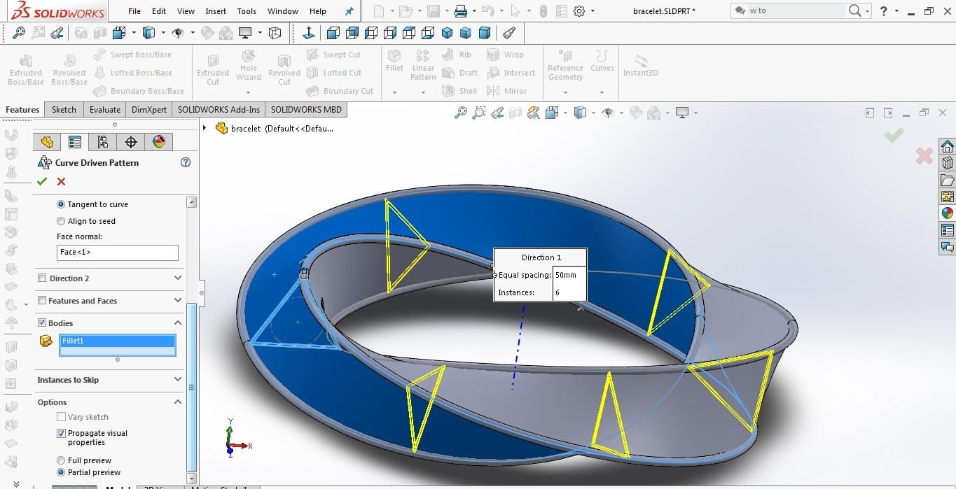
4.Make triangle in 3D sketch using Offset Entities command. Then Use Fillet command.Draw a circle at the end of triangle, use Linear Pattern command.Then right click on edge and close the loop.
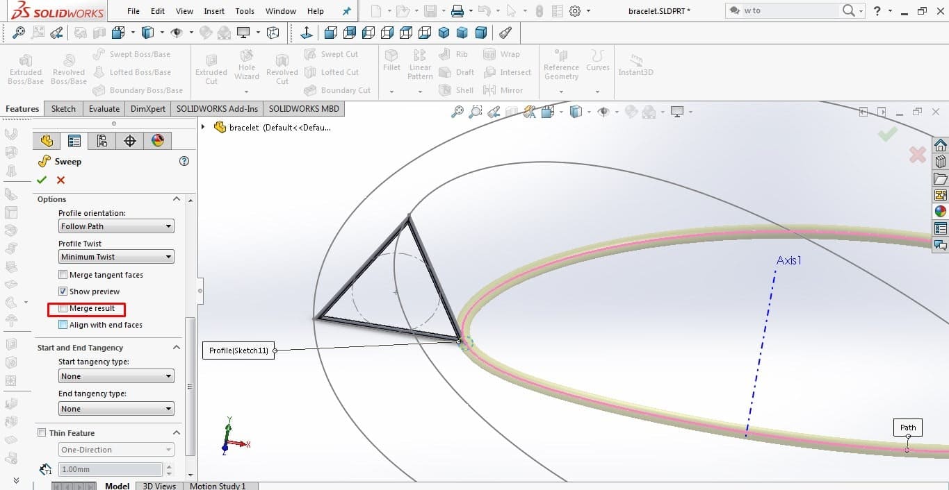
5.Apply same method for remaining two corner of triangle
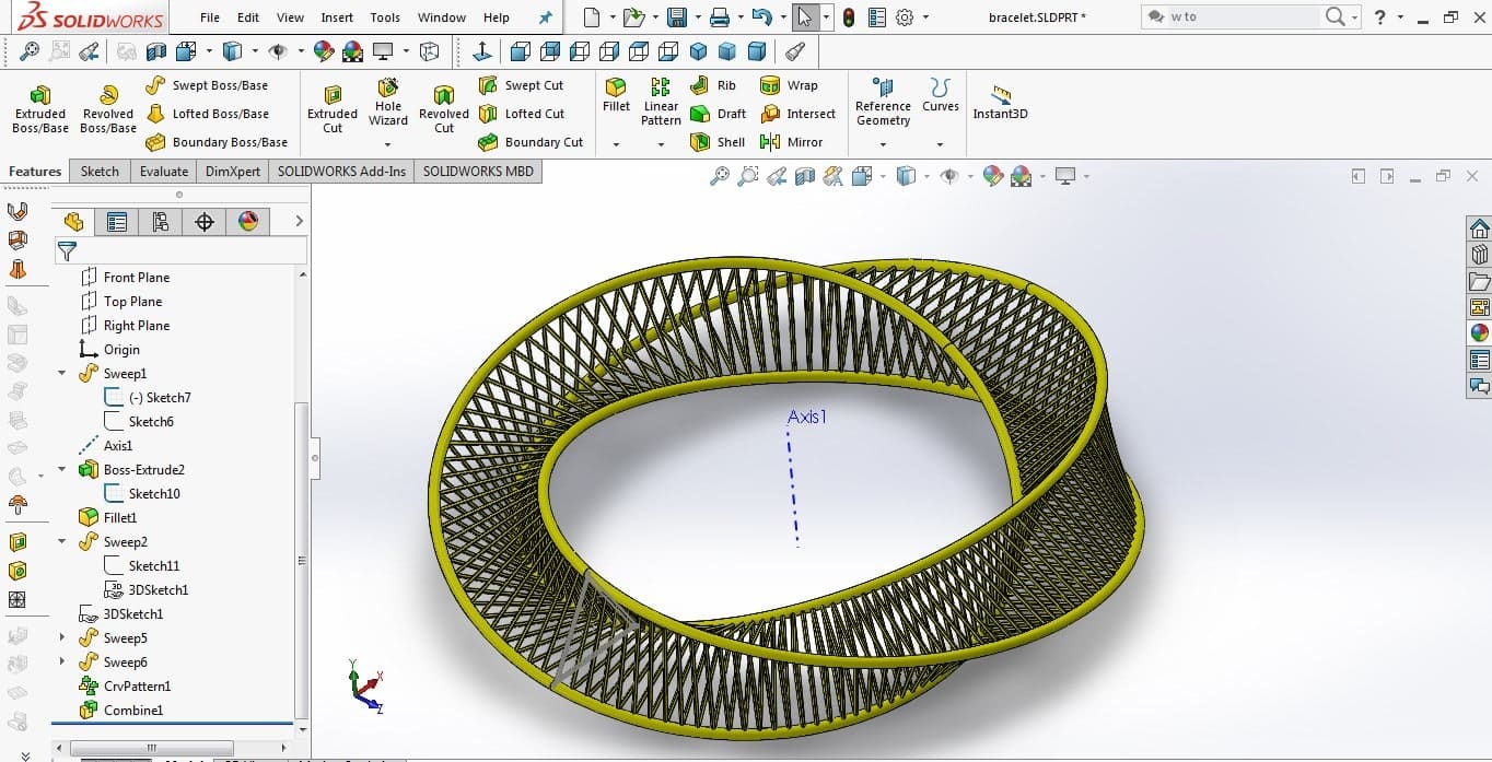
6.After completion, use Curve Driven pattern for making pattern.
7.Designing is done and Ready to print.
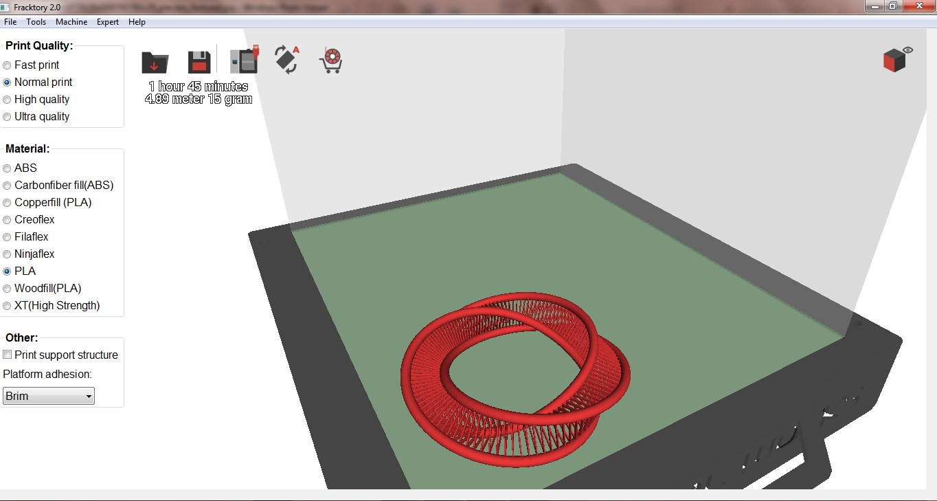
Fractory
Fractory is your own digital factory that delivers 3D Printed and CNC machined components in days. Upload file and place an order on instant quotes in ...
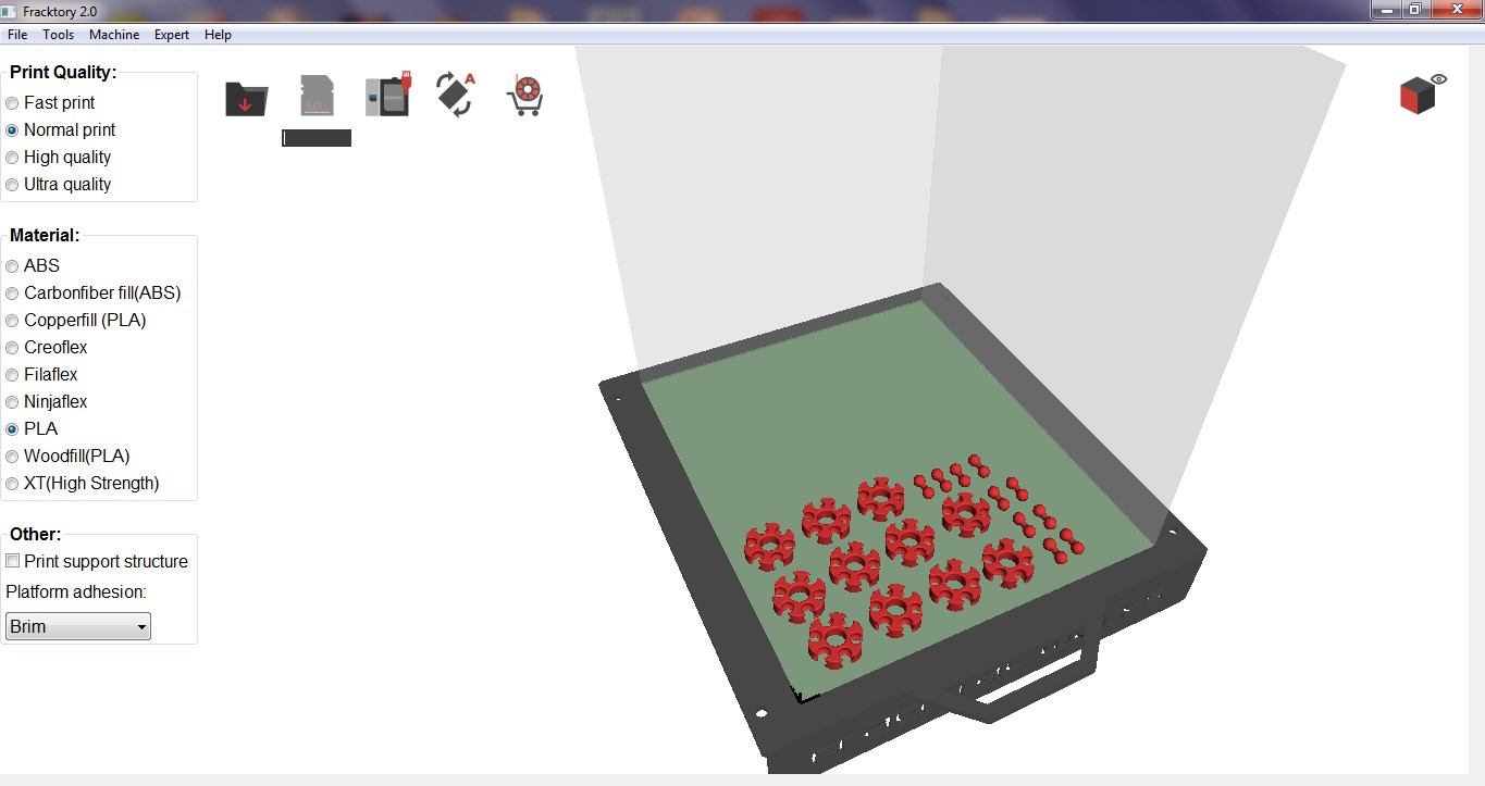
8. Load .stl file in fractal and select the PLA material and Normal print. Save the file in SD card.
After The testing part of an printer I understand about infill and quality.For my individual task I follow this things.For Infill and Quality I took Normal quality
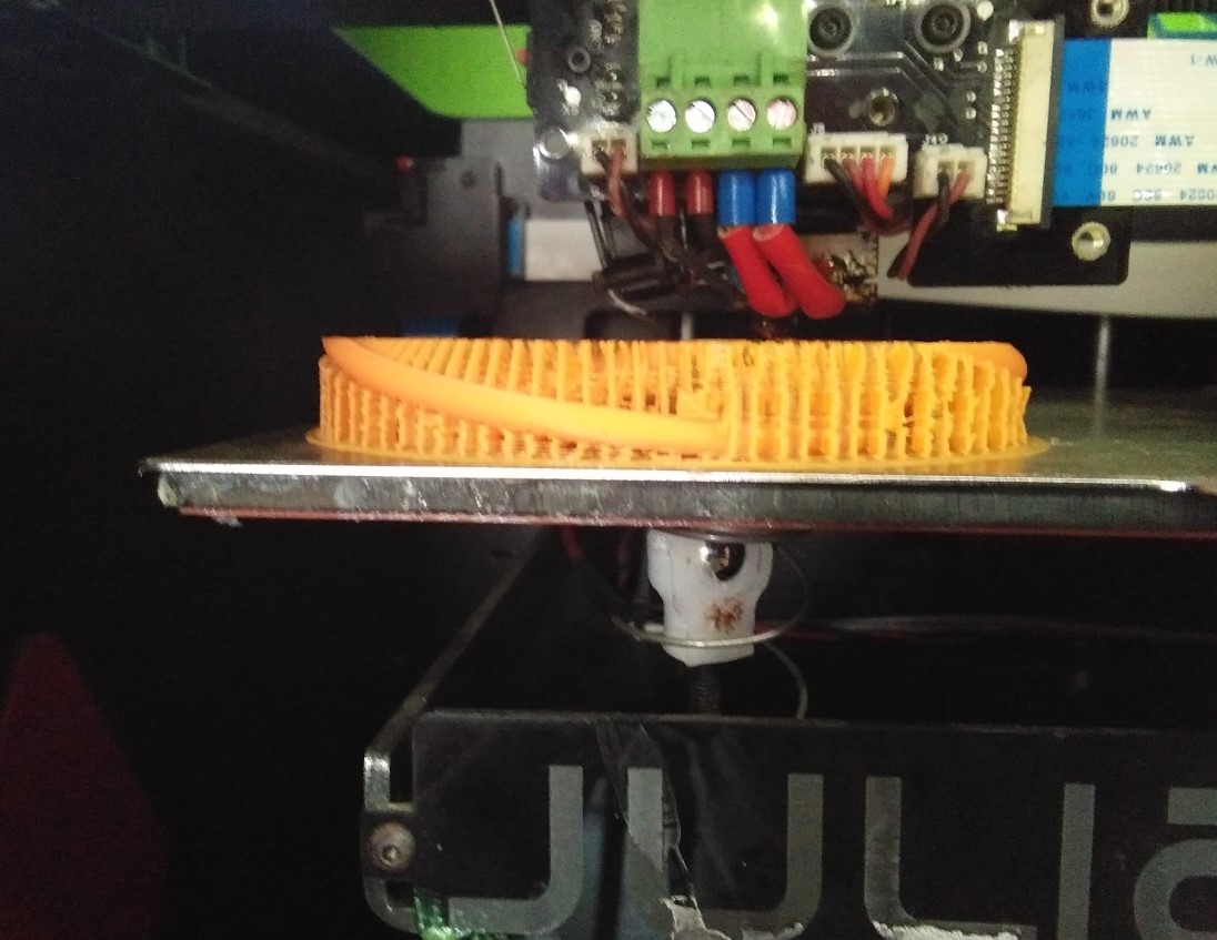
9.First clean the bed and apply the glue for proper attachment of the object with the bed. Printer bed going to heat-up around 210 degree and nozzle 60 degree. After that the machine will start printing.
In this assignment I design mobius shape. But after printing it was broken out from some side. It maybe because my line thickness is low compare to nozzle thickness
|
|
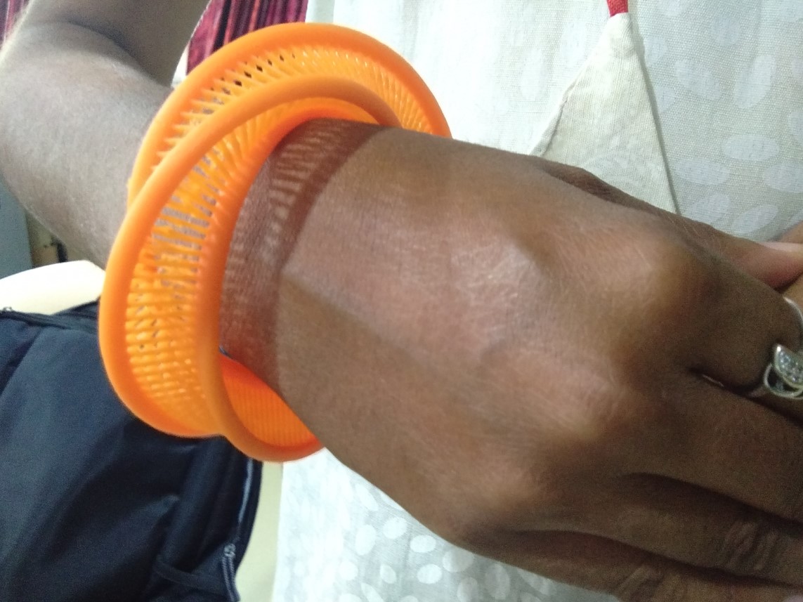
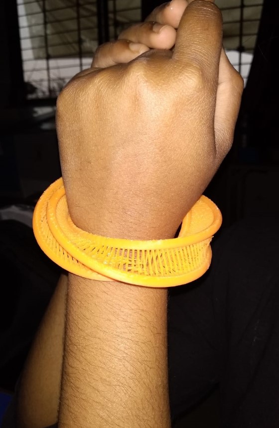
putting it on hand
|
|
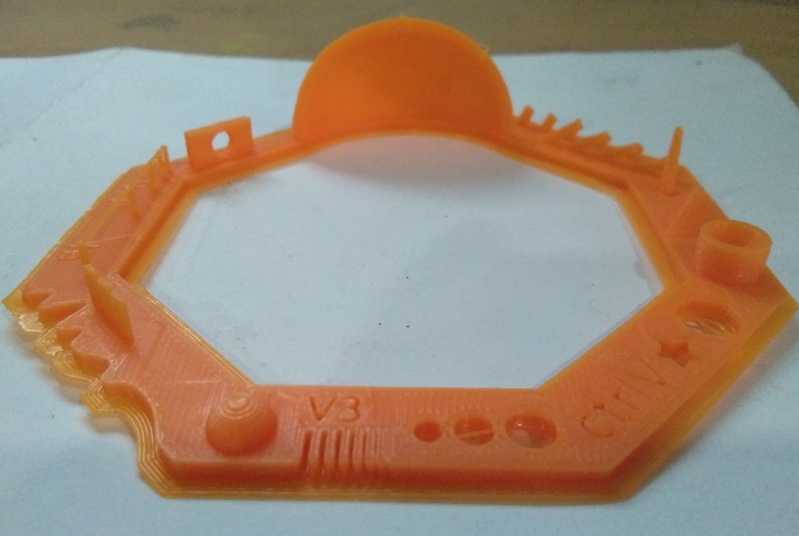
Here I demonstrated three different 3D design. Those design is 3D printed by method called additive printing, Those kind of design is not possible to make through subtractive printing.
Why it not made by subtractively?
This design content many overhang and mesh. The overhang and mesh of mobius geometry can not be subtractive printed.
3D printer can print better than any milling machine. While taking the curve parts in account 3d printer can but not affordable with any milling machine
InterlocksI search for different design on thingivers. I found Interlocks designs that can move anywhere easily. I decided to make it. For designing I used Solidworks. I draw a parametric design which interlocks. First I took a circle and drawn a circle on end points of circle and used Cut revolved command.
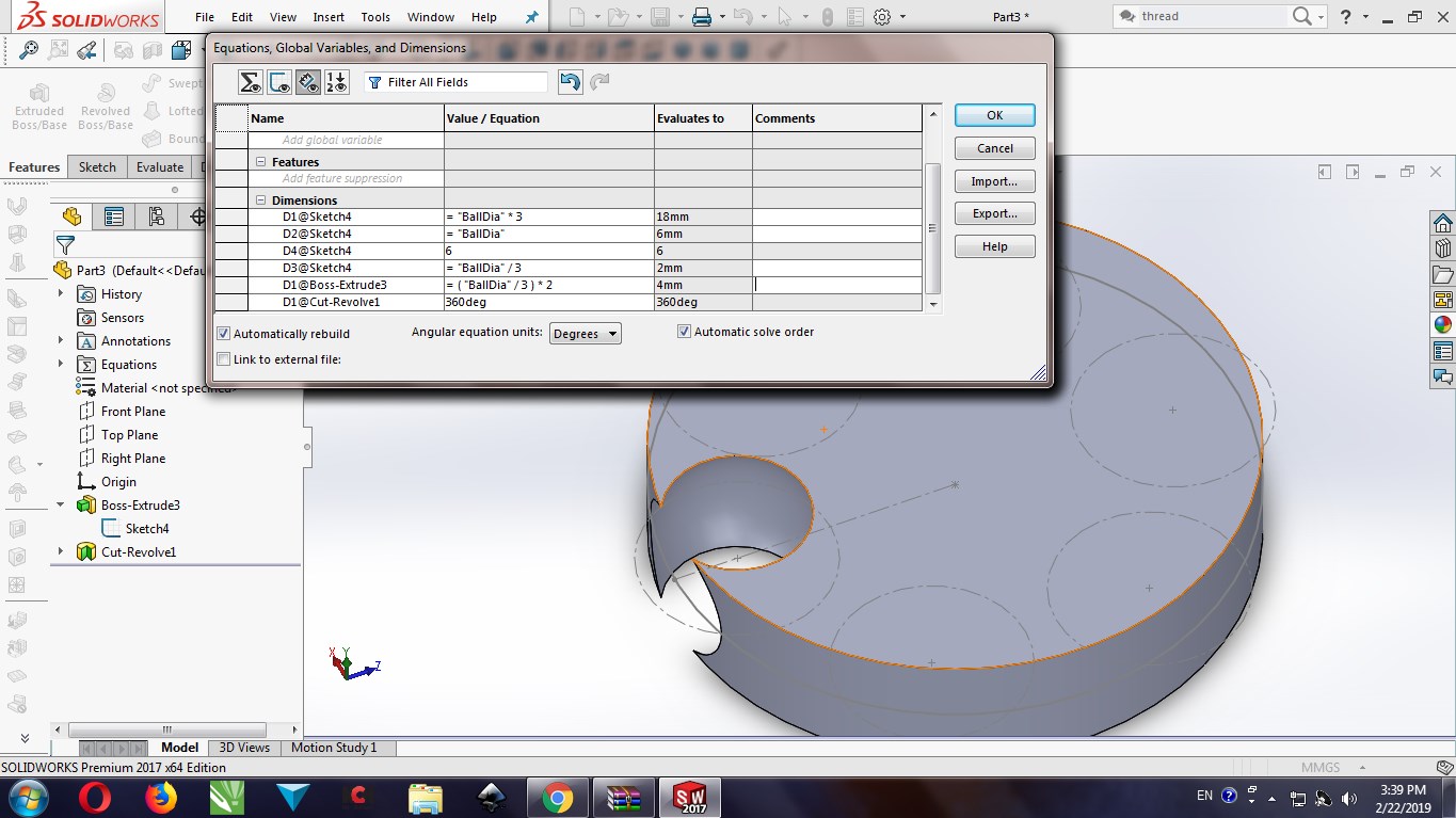
also drawn one more circle at centre of circle and used Fillet Command.
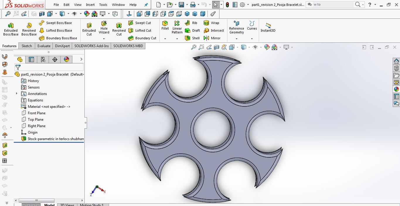
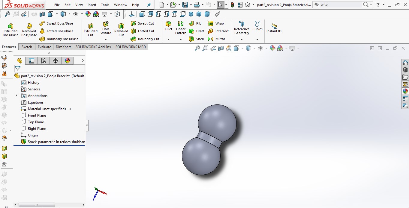
For locking two seperate object I made a connectors with adding kerf.
Open .stl file in fractory 2.0 Software.
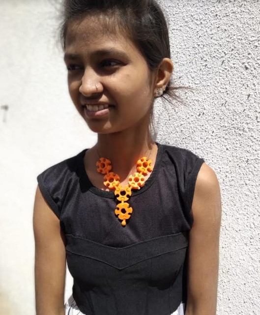
After printing I collected all different parts and assembled it to make Neckless.
Why it not made by subtractively?
I want two seperated object circle and connector.here are the two differernt parts.and also using cut revolved command
I want two seperated object circle and connector.here are the two differernt parts.and also using cut revolved command that's why it not made by subtractively.
Advantages of 3D printing
You can Download Original Files STL file
3D Scanning
For 3D scanning,We have " Sense 3D Scanner".it is the one of the most easy to use and handy. scanner.I downloaded "Sense" Installation file.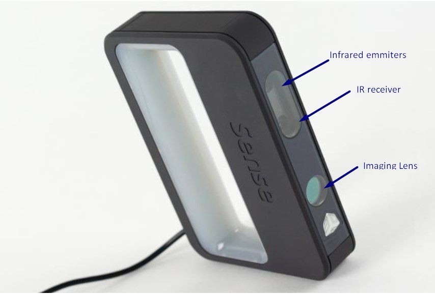
Specifications
Scan Volume:
I downloaded it software and Installed it in my laptop and pluged in the Scanner.
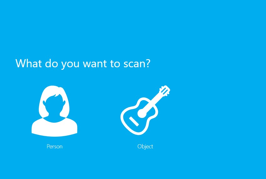
Select the required option If you want to scan human then choose the human and if it an object choose object.
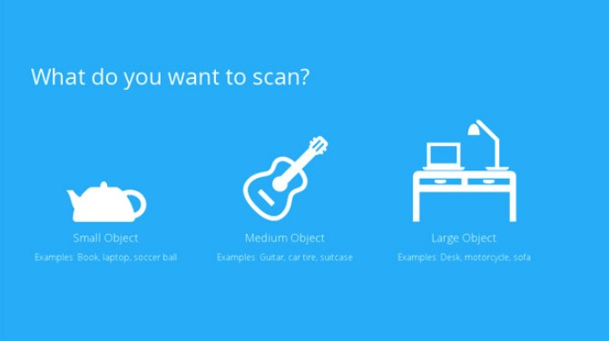
If you select object then it ask whether it is small, medium or large object.
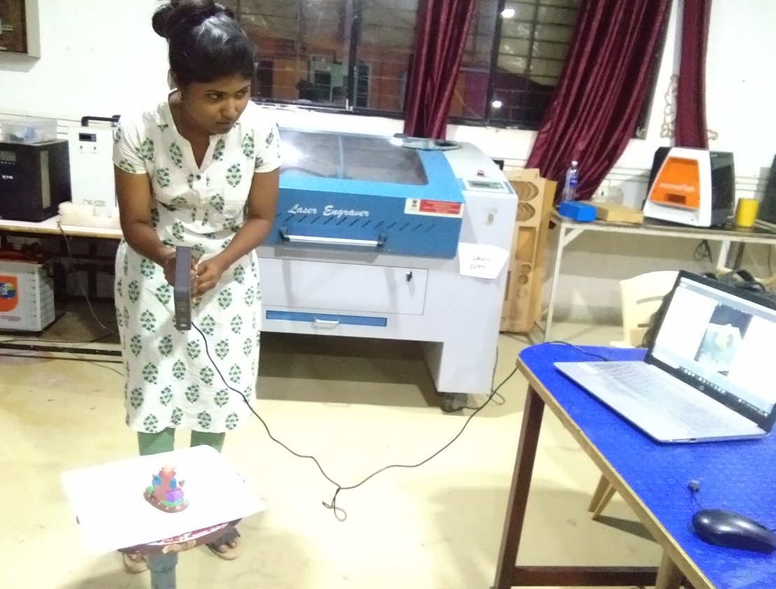
I began with scanning everything around me. my colleagues Aditi and Hemang have helped me. Hemang was in stationary position and I moving the scanner manually around him. This was harder than expected. Later we had settle him on Rotational stool and set the scanner at Place. When we scan that time sense software giveout the Output whether scanned file is good or bad.
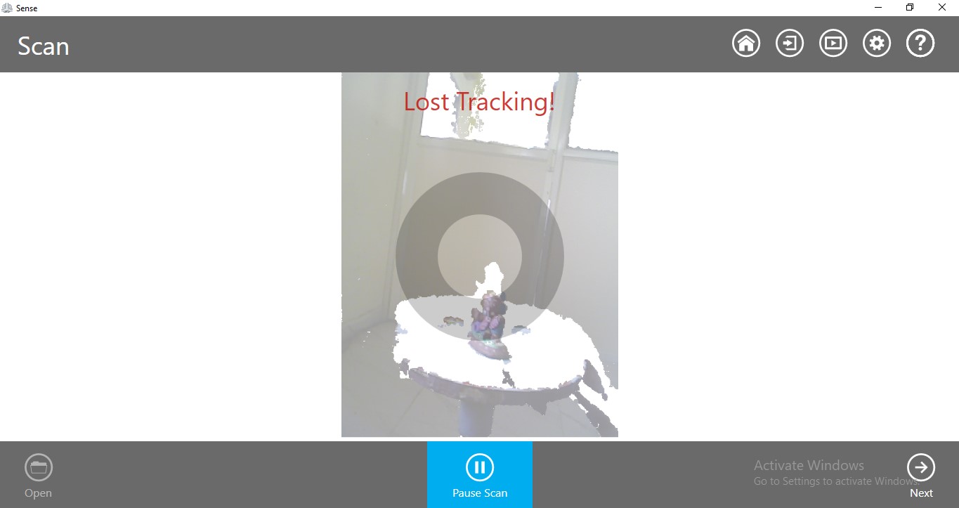
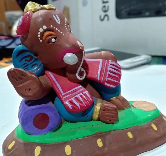
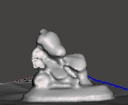
Later I scan small statue of God Ganesha with this scanner. It was challenging task.
First attempt I got lost Tracking.
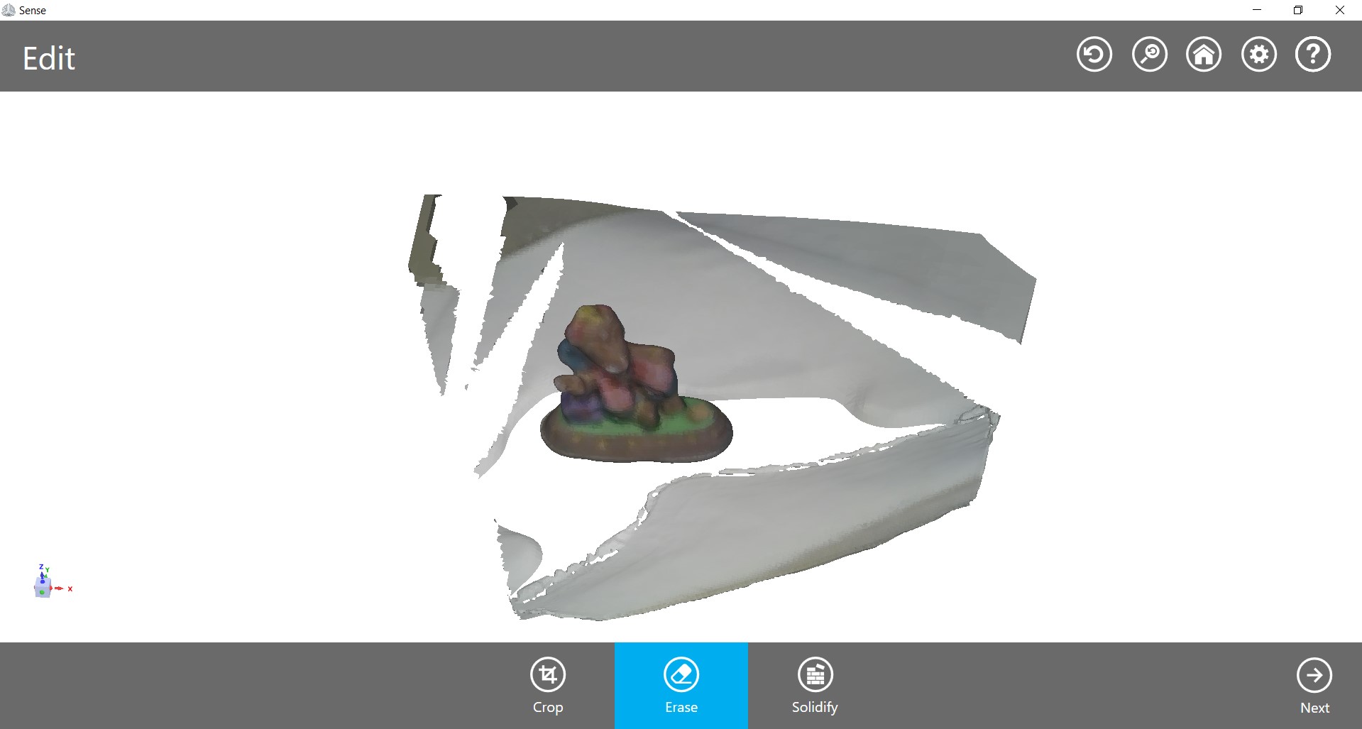
After Scanning....
|
|
Next I scan myself. In this my colleagues Hemang help me.
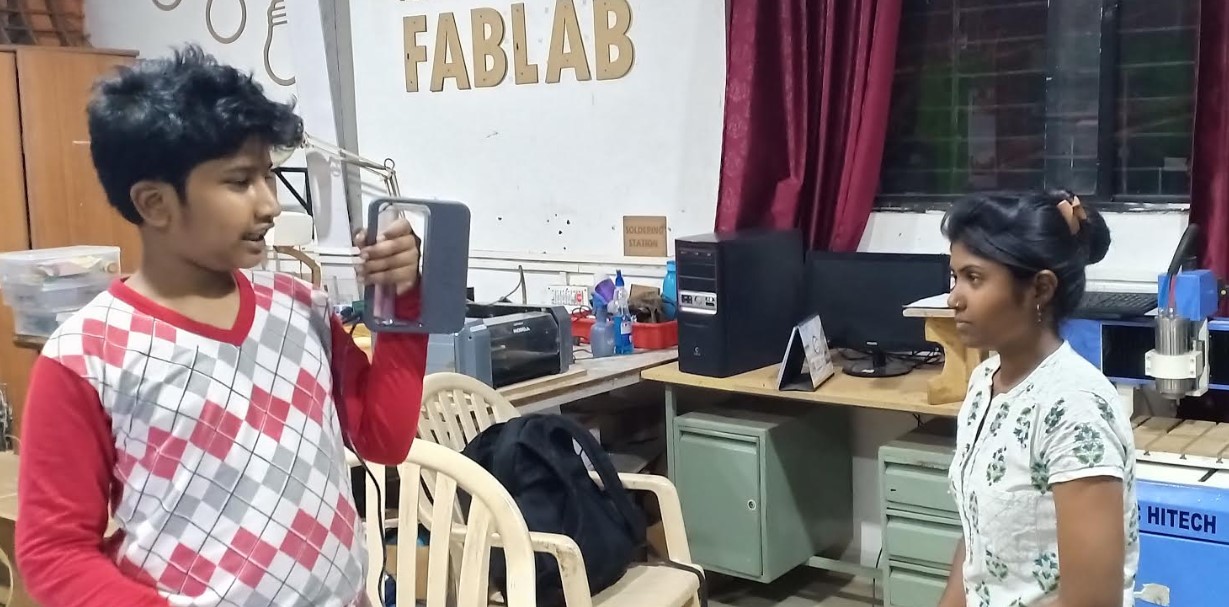
On first attempt my one hand was not properly scanned, it stopped scanning and started to rescan. Light which is reflecting from my face making it difficult to trace. So we move to better place and completed my scanning.
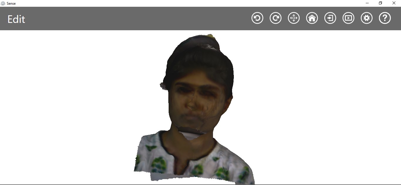
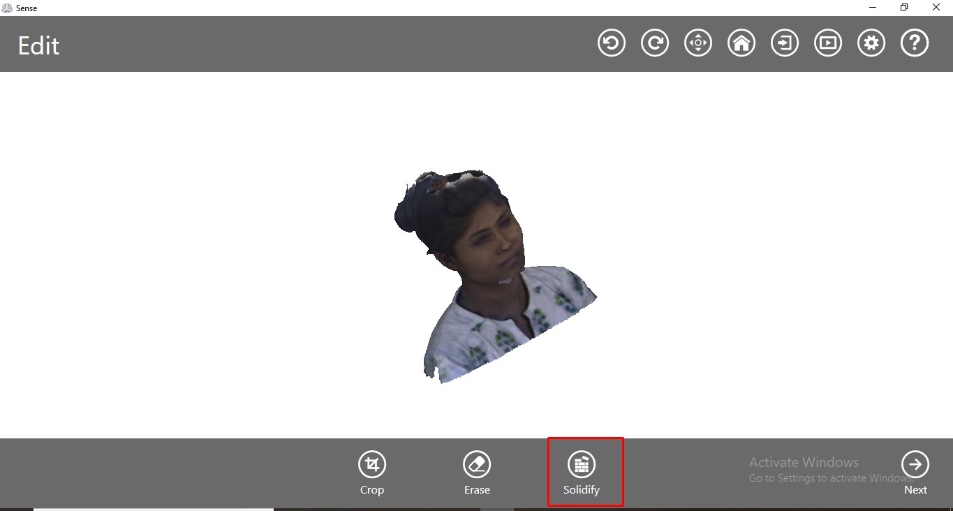
then I edited it and solidify it.
Advantages of 3D scanning
Scanner Quickly capture all of the physical measurements of any physical object. It Saves time in design work. We can easily Replace missing or older parts without CAD design.
Learning Outcomes
This week was very nice because I like 3D printer. I already familiar with 3D printer so I decided to print different small object but really useful. About scanning , I think this is not precise method because its depend upon various factors like stability of scanner, surface of object,etc.
You can Download Original Files STL file