-
Making the giant resistor
Making the giant LED
Making the jumpewires
Transporting the components
Manuals and files
A giant breadboard with the normal tiny components would not help the kids or the teacher to teach or understand how breadboards and electronics work. Therefore it was only logical that I'd look into making the components big to. As I started thinking about this project before the academy started, I had figured out who did what before. I came down to the idea of having a small component in the bigger part. An idea that got backed by the class of electronics production where the example of Sean Hickey was shown.
Eventually it became time to start making the components. I originally wanted to work with cnc milling and molding and casting, but in the end decided for the option of 3D printing, vacuum forming and post-processing.
Making the giant resistor

The idea of a giant resistor already took root in my mind at the beginning of the FabAcademy cycle. During the Computer-aided design week I already took the liberty to draw a part of the components that I would need now. At that time it was merely a visualization of it and nothing concrete.
While thinking about my plan ahead (how am I going to make this?), I came up with two options. The first option was to 3D print the resistor in 2 parts, add the component and glue them together. The second option was to 3D print the whole part at once.
First option: resistor in 2 parts
I started with cutting my original design in Onshape in half and removing the 'wires'. But didn't make a space yet for the actual resistor. I wanted to calibrate the 3D printer first, and see if there would be warping showing up whilst printing.
The next step was to add space for the electrical wires and the resistor. I took them big enough so that there is enough air around it for possible cooling, but also to have the possibility to have a much bigger resistor in it. As this is just the hull, you can give the resistor the values that you want. Once again, those parts were printed out, with support, and they came out fine for what I wanted to do with it.
 Printed the 3D prints.
Next on the to was to do the post processing of the print. I often work with epoxy and composites and when you really want to have something smooth, you can use spray putty. This also works on 3D printed parts, so bought myself a new can and went ahead. I gave 2 base layers and started sanding down after that. It's no problem if the first 3D print starts showing. After several layers (3 to 5, printed on 0.2mm) all holes were filled and you have no way of seeing that this is actually a 3D print.
 Post processing a 3D print, the print after one layer of putty.
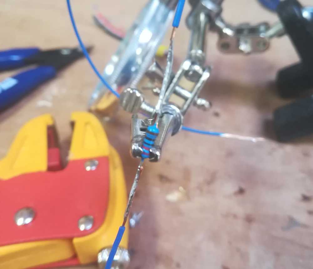
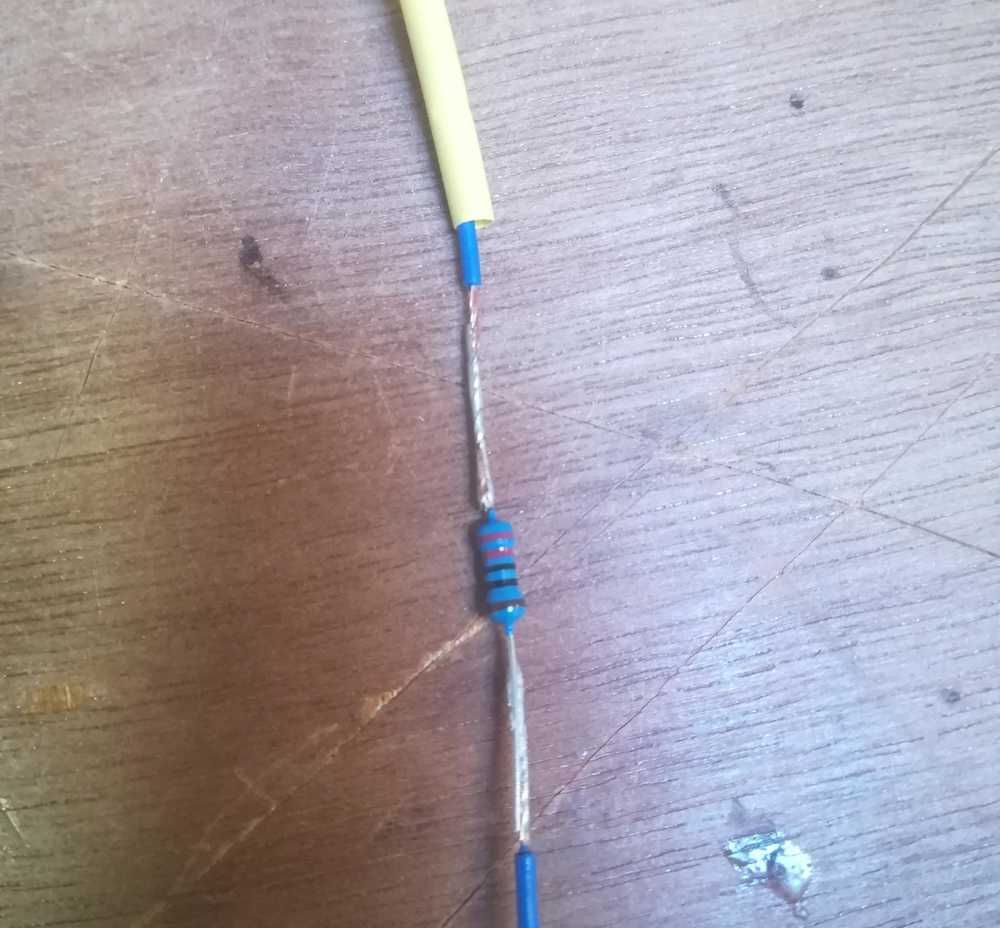
While the hull was drying between each layerof spray putty, I took care of the actual electronics inside. I took a 220R resistor, as we use those all the time with LED's in the lab. I soldered two wires to it and secured and protected the whole thing with a heat shrink tube.
 The original resistor
 Soldering the actual resistor to the wires.
Once this and the hull were finished, I glued the 2 parts together. Once that was dry I put the electronics inside and secured them with a little dot of hot glue.
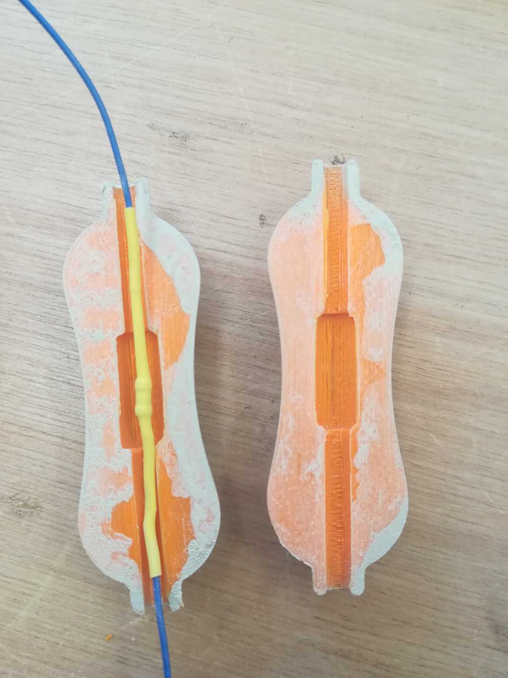 The inside of the part.
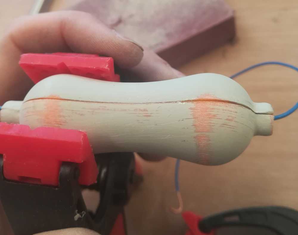 Glued the components together with second glue and used a clamp to secure it for a minute.
The last step is to spray paint the whole giant component and give it the right values.
Second option: resistor in 1 part
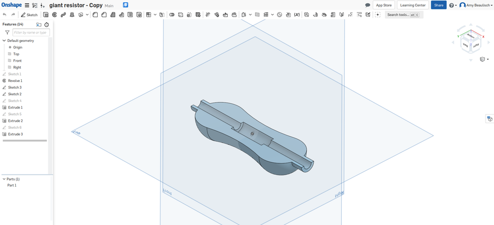
The workflow for this part is mainly the same as for the first workflow, but here is the detailed description anyway. I started with removing the 'wires' in Onshape. And make place inside the part for the electronics that it would house. As I build further on the first version (see up), there is again enough space for air and components within the part.
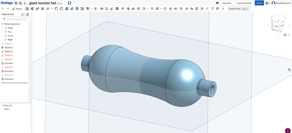 Full resistor in Onshape
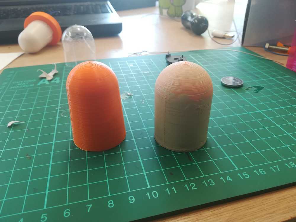
Next was 3D printing the part. Out of habit tfor wireshe support was on and it filled the whole part with support. Not what I wanted. I tried to take it out, but it was to much of a hassle so I decided to take the column drill and just drill through the support. You might be wondering why I didn't just turn the print, well I'm afraid that the support will leave uglier marks then than how it is now.
The nest step was to do the post processing of the print. This is the exact same process as was describe above. Make sure that you finish with a very high number of grain of sanding paper to get a soft and smooth feeling. While the putty was drying I also took care of the electronics here.
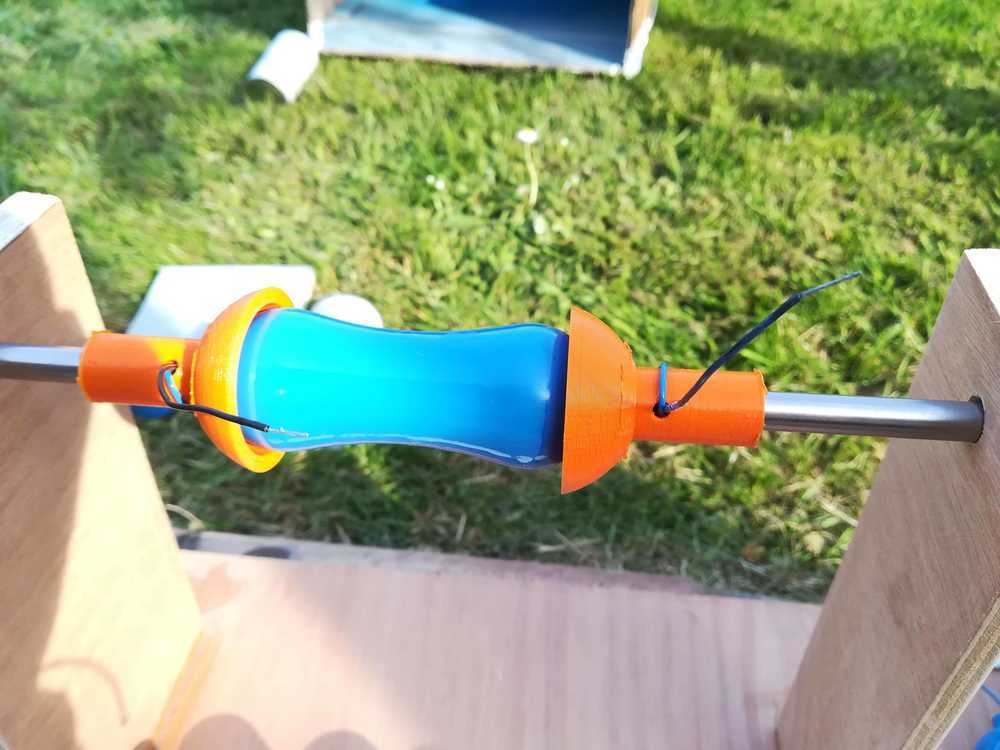
Once the hull and the electronics were ready, I assembled them, and secured everything with some drops of hot glue. The next step is to spray paint the component. As this was still a first try I took a black can of paint (we didn't have anything else) and made myself a small spray cabin where I could hang my newly made resistor. On safety and health: I did this outside with some wind so that there would be no danger for me. The part also dried outside and not in the lab itself.
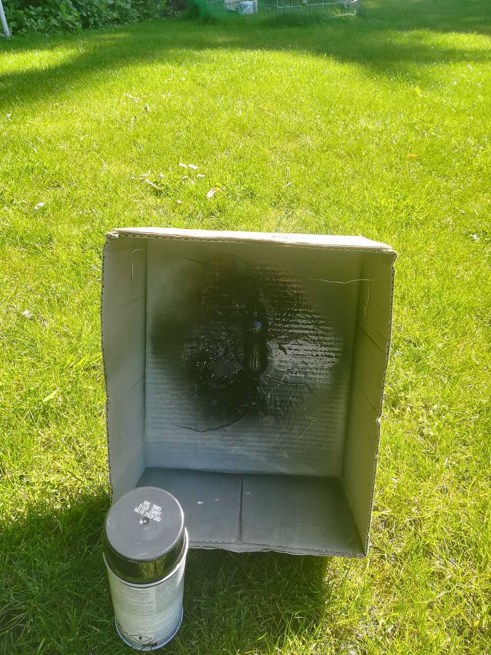 A box with a wire became my spray cabin
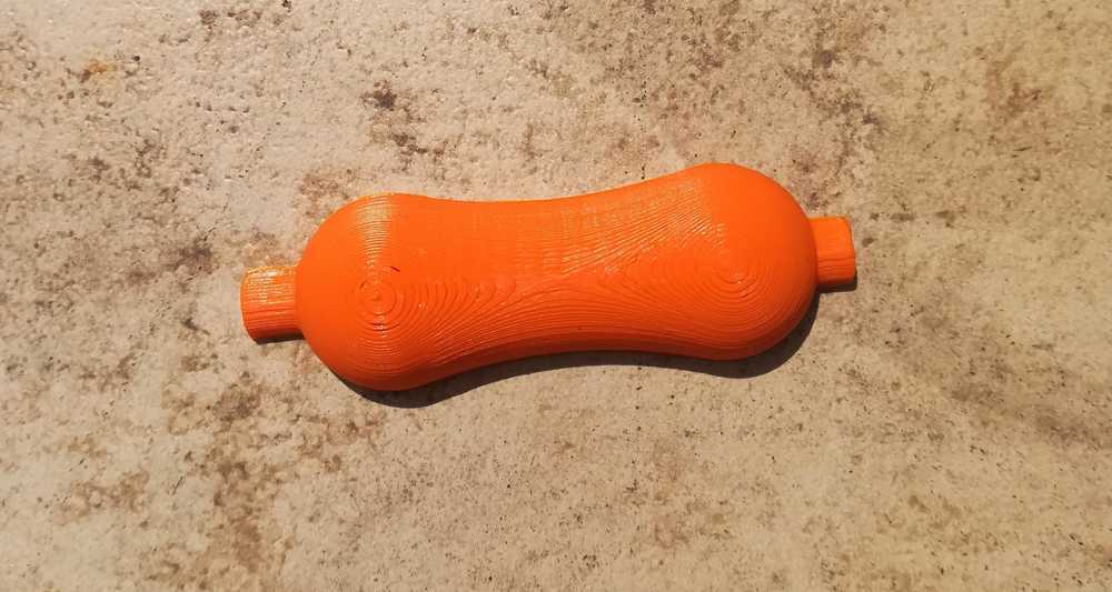
 The result when sprayed
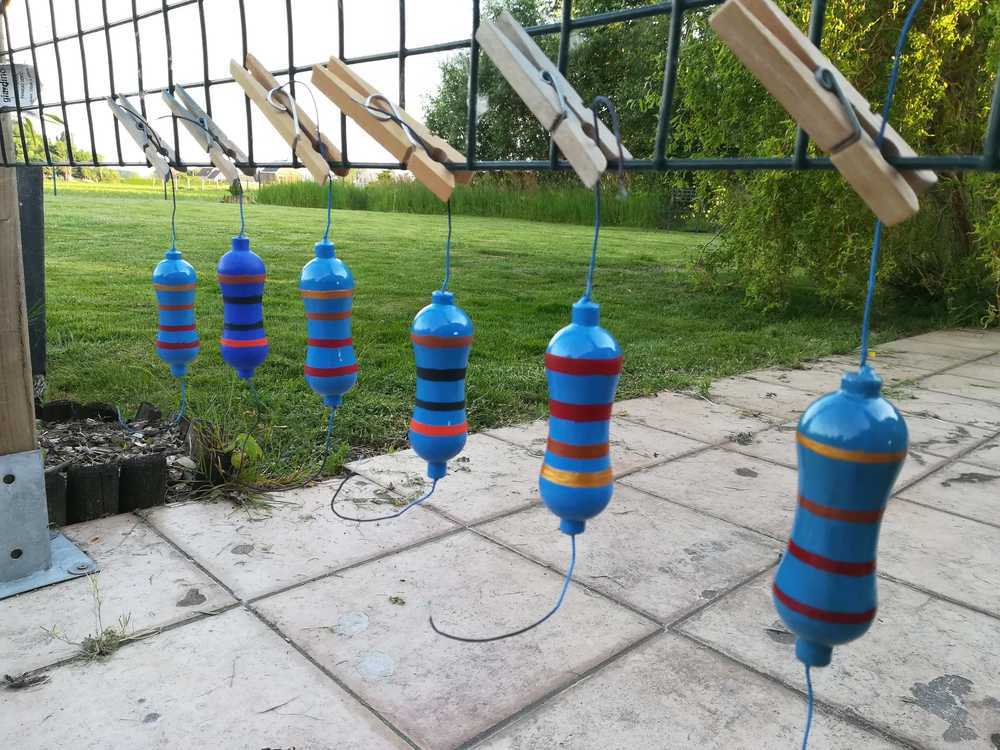
The last thing left to do is to give the resistor another base color and to put on the values
 The resistors out of the 3D printer and sprayed in base color
 The resistors out of the 3D printer and sprayed in base color
 The resistors out of the 3D printer and sprayed in base color
The finished part!
 The resistors out of the 3D printer and sprayed in base color
To top
Making the giant LED

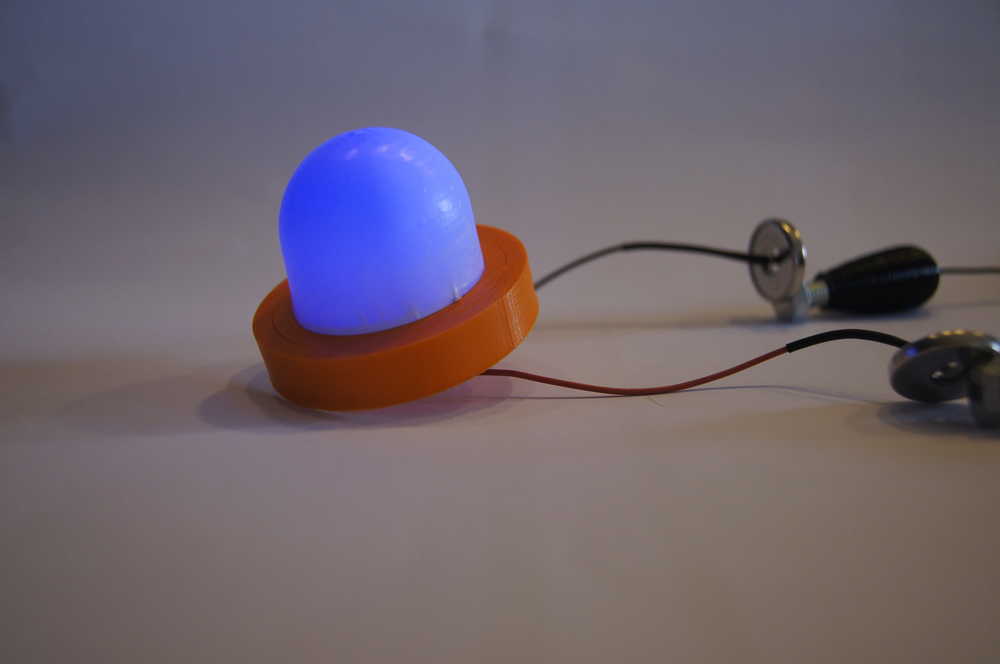
Giant breadboard, giant resistors, so I felt obliged to also start making a giant LED. At first I though to make a mold and use clear epoxy resin to make the bulb of the LED. The base for the 3D print has been stable in matter of ideas. The thing is, I wanted it airy inside, and modular. There are lots of giant LEDs out there on the internet, but with all of them I had questions about the array of LED's in it and the cooling. Because yes, even LED's get hot after a while.
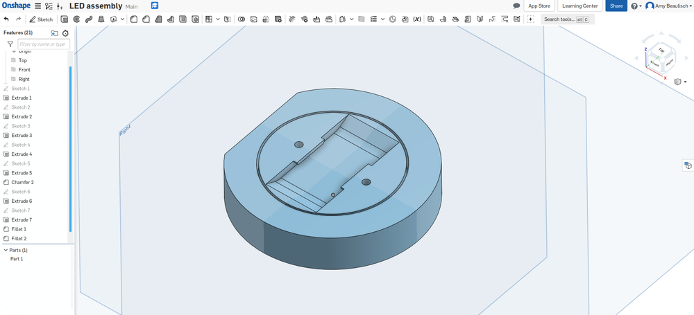
I started with the 3D print. LED's tend to be round, but with a straight line at some point (the minus side). I wanted to replicate this to, so back to the drawing table, I mean, Onshape
and drew out the base for the LED.
I made a extra circle inside to connect the bulb to the platform, 2 holes for the connections for the LED's-Wire connection and some space to put, eventually a small PCB inside.
While I was printing the base, I had time to draw out the bulb. I used 3D printing for the mold and vacuum forming for the actual shape. Most of the components were made without to much trouble, but here I had to restart over a few times. A chronological description of trial and error:
- Puttey and vacuum forming
- The height of the part
- See through or milk frosted?
- Draft
- Height
After the 3D print was done, I post-processed it with spray putty just like I did with the resistor parts. It all went well, I had a nice, soft shape, and no hints that it was actually
a 3D print. The thing is, I tend to be impatient and probably put the part in the vacuum former before the putty could completely attach to the print. It might be dry enough to sand it down
but not combined with the heath of the press.

I know that the height of your part and the thickness of your material is crucial when vacuum forming. But I wanted to test my limits. This ended up with my first part not only scalped of the putty, but also having a lot of side structures. Like a racket had in the old days. Not what I wanted. I did proceed with cutting it out and test if the part fits on my 3D print. It did! The plastic however had severe damage.
Another question arose: do we want the LED bulb completely see through or milk frosted. We have both materials in the lab and I proceeded testing both. We all came to the conclusion that we like the milk frosted one better.
On my first test part I didn't put a draft, something that I should have done. So, I changed my drawing and retried. Sadly the height was still to much and I never got my print of of the plastic without breaking the plastic
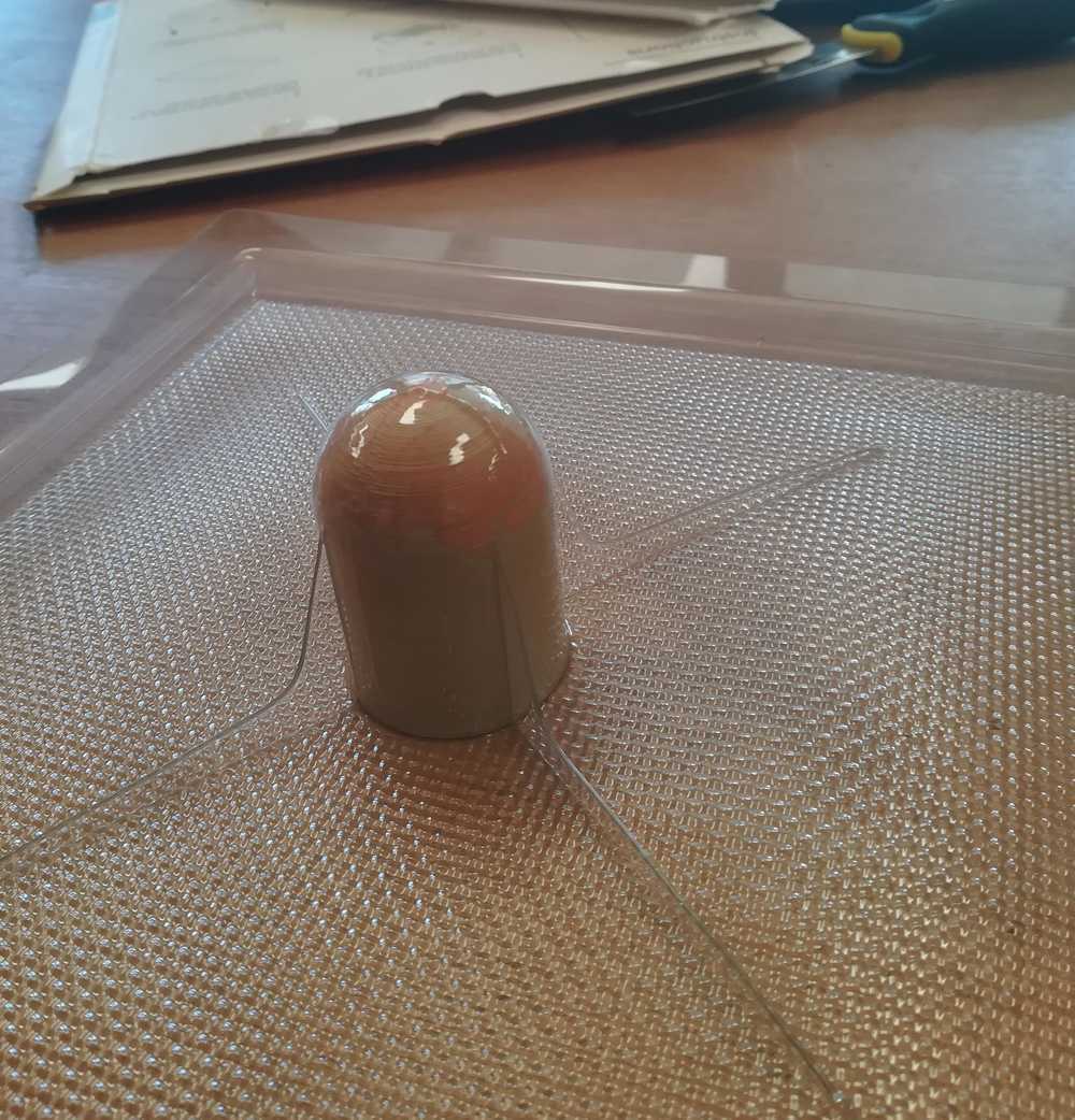
Already mentioned before, the height is important. I decided to cut into my first 3D printed part and lower the height from about 5cm to 3,5cm. Not having any electrical tools near, I used a hand saw to cut into the piece. I vacuum formed the piece again and had a great result.
The finished part!
To top
Making the jumperwires
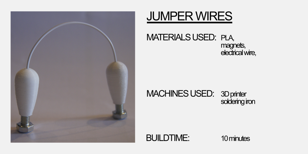
Of course all those components need to be connected to the giant breadboard and to each other. Over the course of the FabAcademy, we've had several ideas on how to connect the components to the giant breadboard. But we always came down to 2 solutions: loop and hook (velro) and magnets. Other options that we explored were screws, push buttons for textile... The main question all the time was: are they conductive? How do we connect them to the components? Is it strong enough to hold everything?
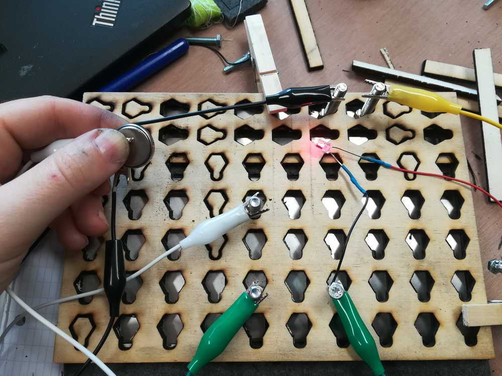
During the first tests that we did, with conductive materials and the grid, we noticed that maybe magnets could be the best solution to our connection problem. During one of the tests I took the magnetic board from home and connected the magnets with electrical wire to it. It worked like a charm.
 Test with conductive materials and magnets
Before I started designing a hull for the magnet and the electrical wire, I wanted to give the wire and the magnet a more stable connection. They often came with me on the train and in the car so they also came loose very often. What I did forget was that if you solder magnets, it looses a part of the magnetism. So that wasn't a good idea.
As I couldn't solder the magnets, I needed to find a new solution. The first idea I had of putting the magnets and wire into a tube came in handy. I changed the tolerances a bit so that there was extra space for the electrical wire in the tube. After a few tries and prints, I had a working connection!
The way it was described above, is of course the easy version of the story. I had to tackle several problems prior to being able to finish this part. The first one was that my printer did not print perfect circles. I mentioned it in the 3D printing week and now was the moment to fix it. It was actually done very fast by adjusting one of the belts.
 Circles prior and after adjusting the machine
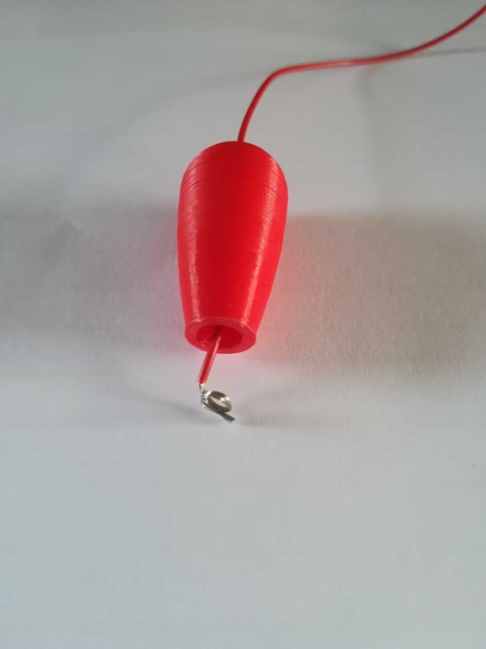
Once all the pieces were fitted, printed and fitted, it was time for assembly. The whole procedure is pretty easy, just a bit painful on the fingers sometimes. You take the electrical wire, strip about 3cm of the isolating material, twist it around the magnet (through the hole) and put the wire through the 3D printed part. After that you push the magnet in in the print, and use the table to give it one last push. The wire now will also be stuck between the print and the magnet, making sure that you have a good connection.
 The magnet and electrical wire connected through twisting. You can solder the twisted part if you want. This is a common method that we use in our classes
with the younger kids.
The magnet and electrical wire connected through twisting. You can solder the twisted part if you want. This is a common method that we use in our classes
with the younger kids.
To top
Testing the magnets with kids
During the Easter holiday I worked very hard to get my first prototypes ready. Not because I wanted to get ahead of the Academy, but because we actually had a programming workshop then.
The perfect moment to test out the giant breadboards. And the feedback was... devastating.
The children did however understand better how a breadboard worked, but the connections of the metal pieces and the magnets were to weak to make it work.
During our tests at home, we noticed that you need at least 2 magnets in the cylinder, whilst knowing this, I only put one in each cylinder. The test failed, but our approach of giving the
children a bigger breadboard does work.
 A mini version of what we tested with the childeren
But magnets came also back on the giant breadboard for teachers. As we can't put a magnetic plane behind the breadboard there, we needed to find another solution. Our salvation came in the form of Beckaert Industries. We managed to get to talk to them and pitch the project. The liked it and gave us some sample materials that we could use. Even though, it was all made from steel, we didn't expect the magnetic properties to be so good. We mainly focused on the conductive part there. But it turns out that they have a 'textile' that's perfect for our biggest breadboard and is both magnetic and conductive.
 Magnets pushed into the 3D print
To top
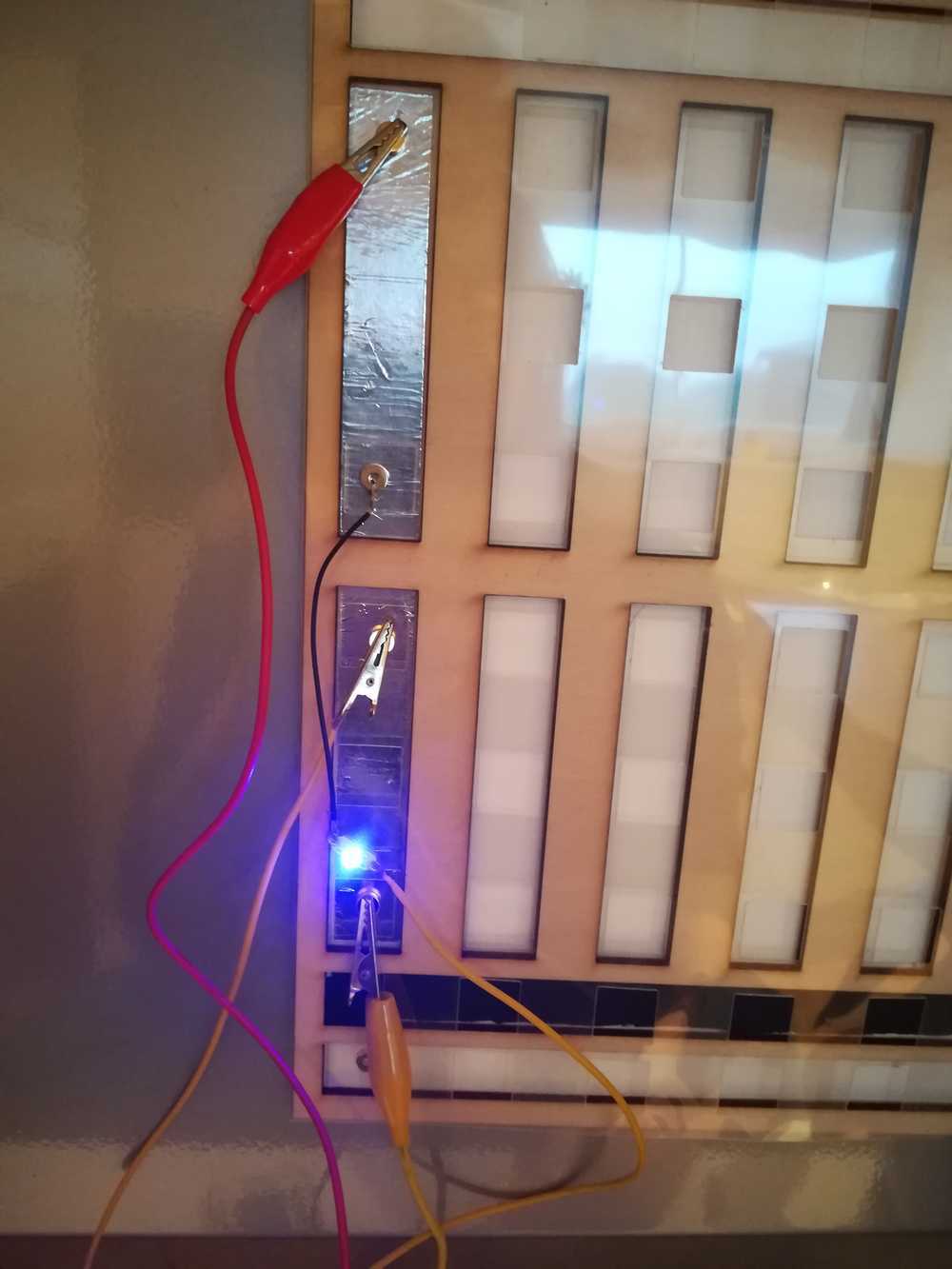
Loop and hook
We knew about the existence of it, but we needed to get it in our hands: conductive loop and hook (velcro) materials. I tested the connection by sewing the pieces of velcro to filt and pushing them together with an electrical wire in between. It worked. The next test was to see if we could wrap the wire around the velcro. It worked. But we never evolved to sewing the electrical wire to the velcro and make it an actual connection.
 Conductive loop and hook materials
Bolt
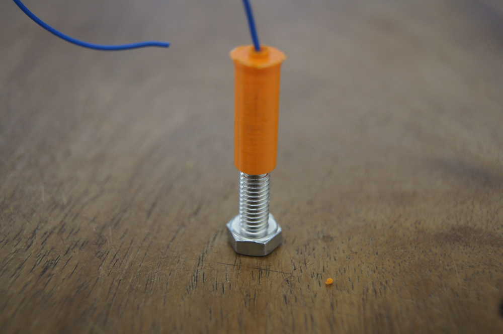
The bold-connection was something that we came up with when we realized that maybe the magnets would not be our best option and due to other problems described in the part where I talk about the breadboard development. Even though we could solder those to the electrical wire, we decided not to do so. But go back to our first idea of the tube and the magnet. I changed the drawing of the tube so that we're having metric thread in it and that it fits on bold. A solution that works fine.
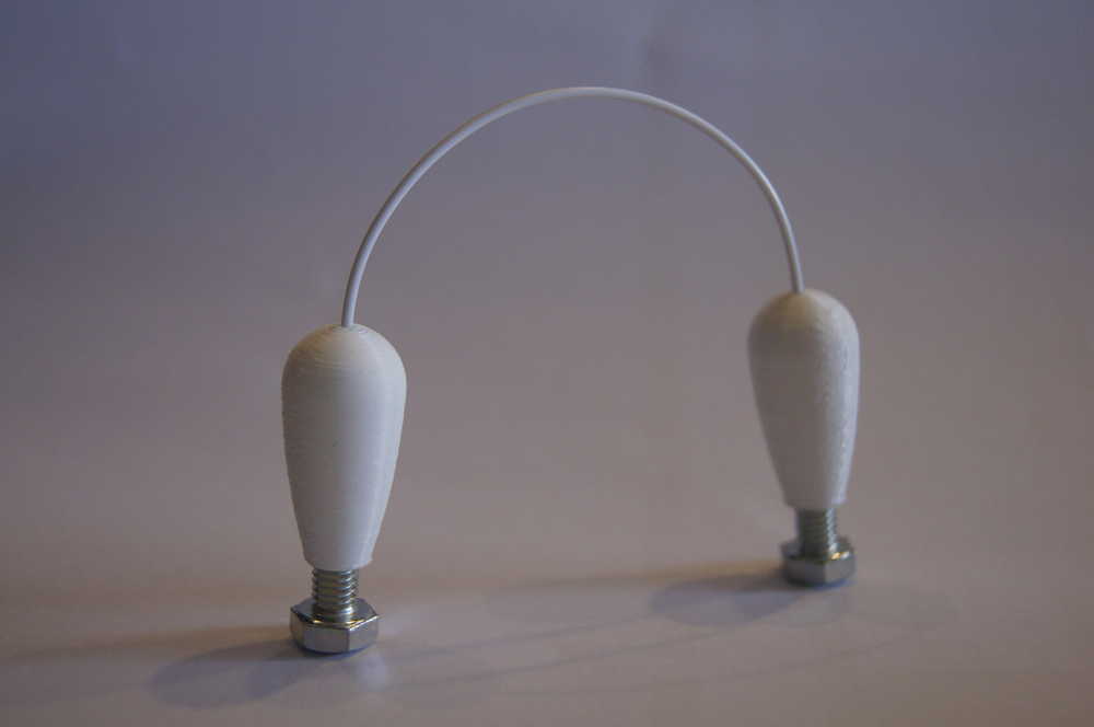
 Connection made with the bolds
 Connection made with the bold and 3D print.
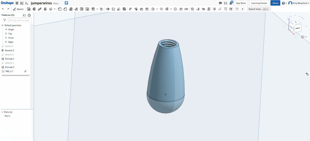
Once I got a bit futher into the development of my final project and saw that I would have enough time, I started redesigning the 3D print parts for the jumper wires. The first print showed what I wanted to do, but it's not exactly pretty. I went back to my drawing table - I mean Onshape - and started redesigning the connector.
To top
The main problem here was that I wanted to have metric screw thread in the part so that my bolts could be rotated into the part, pushing the metal wire to the top, garanteeing a good connection. A question that I often got later on was if I used a special tool to make my metric thread, but no, my printer can go fine enough to have a perfect thread.
 Connection made with the bold and 3D print.
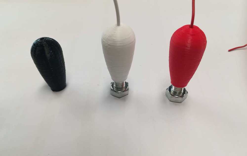
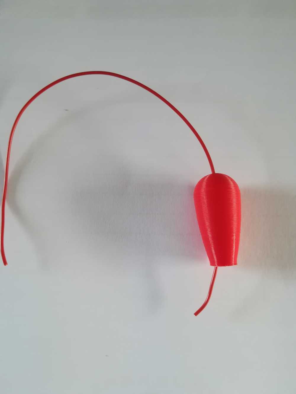
While waiting for prints to end, I also realised that I needed at least 3 colors for the connectors. Red, black and white. Red stands for everything in the jumperwires that is positive. Black stands for everything that is negative or goes to ground. And white is neutral and will be used as empty jumper wire or for the resistors.
 Connection made with the bold and 3D print.
The finished part!
To top
Assembly of the jumperwire
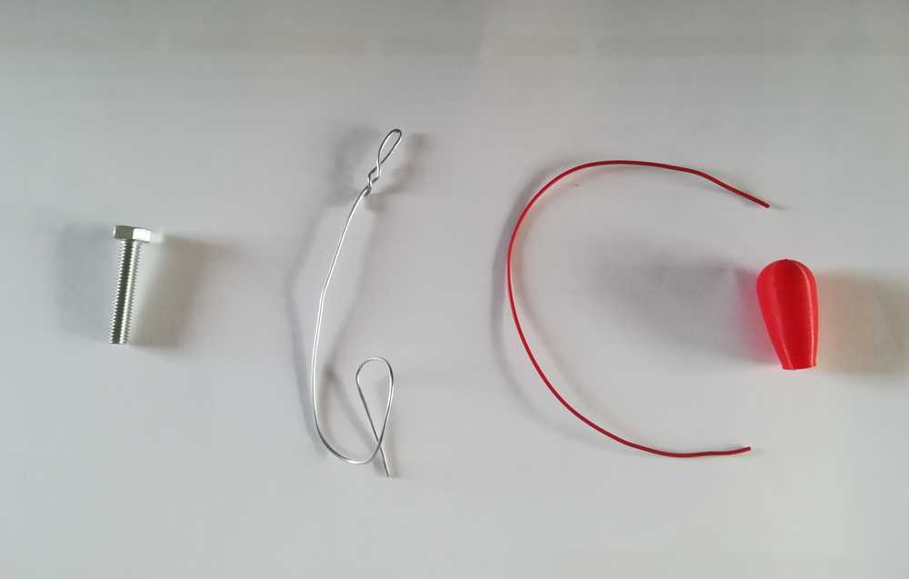 Gather all your materials: the M6 bolt, a metal wire, an electrical wire in the right color, the 3D printed part.
 Push the exesive material away in the 3D print with the metal wire. Print without support!
 Push the electrical wire through the hole in the 3D print
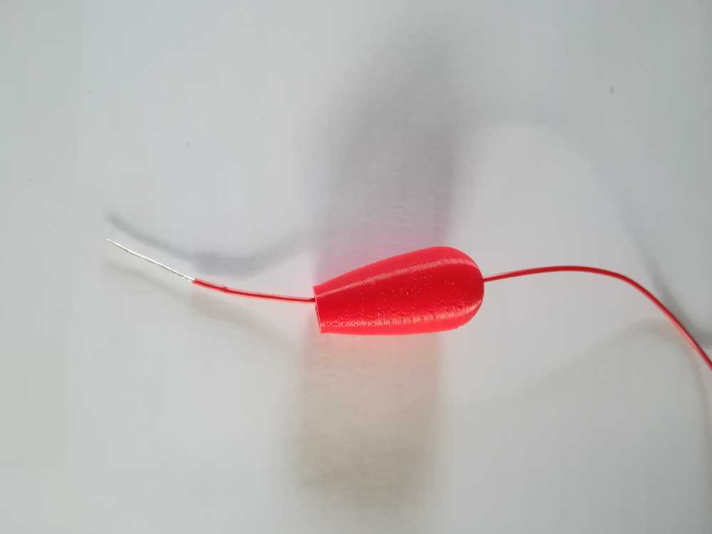 Strip about 3 cm of the electrical wire.
 Twist the wire so that it becomes round and pull it back into the 3D print.
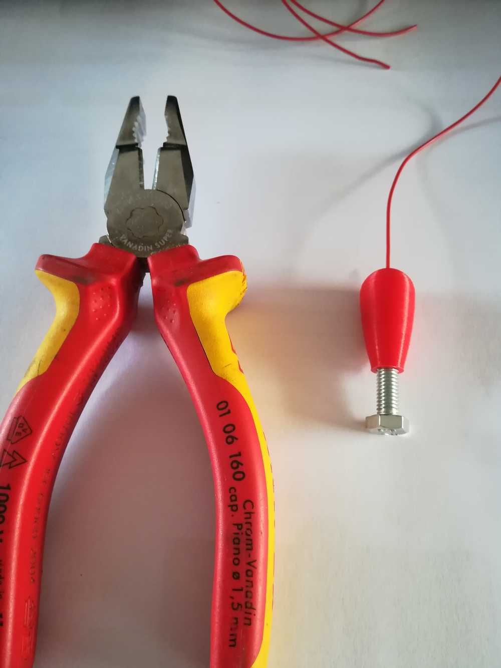 Twist the bolt into the 3D print, use a plier for the last part. Be carefull not to go to far as you might break the 3D print!
 All done! Do this again to the other side and solder components in between.
To top
Transporting the components
A thing that a lot of projects seem to forget is how to transport the project, if that is needed. As we are giving workshops all over Flanders, Belgium, the giant components need to be protected against travel. Therfore we decided to make little travel boxes for them.
The giant resistor
For the giant resistor storage we decided to go for a stacking system that fits within the main box. I gave the team several options on what could be the best possible solution to stack the resistors into the box.
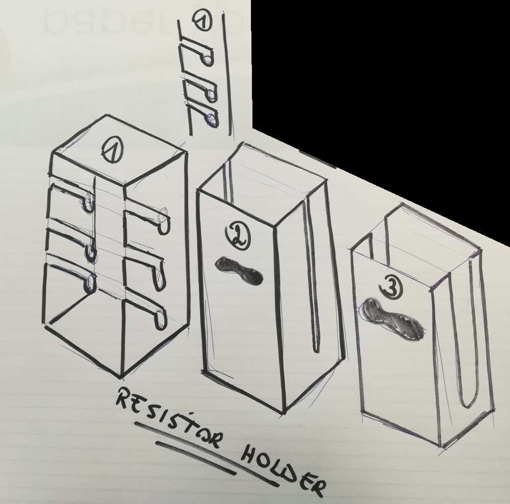 Sketch of the possibilities to have the giant resistors stored.
To make the design file I used our boxmaker. The kerf has ben standardised in the software and it's the fastest way to make boxes.
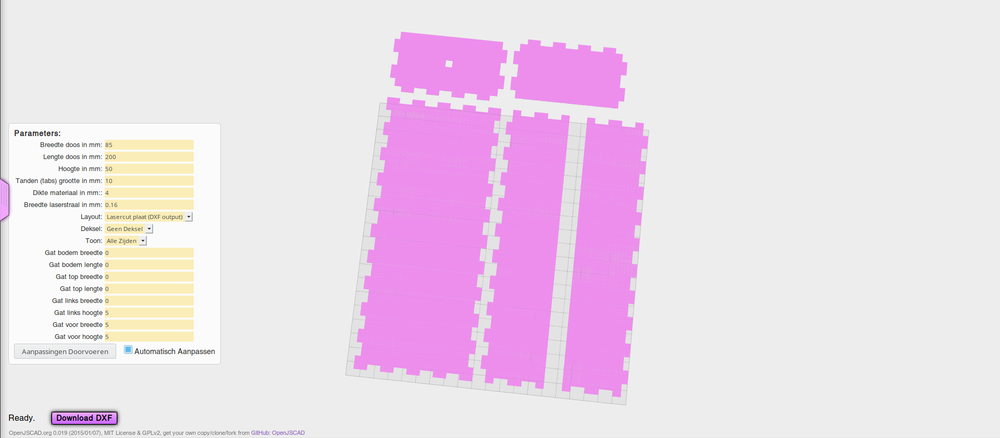 The boxmaker adapted by the Ingegno MakerSpace
After making a small mistake with the lasercutter (used the wrong thickness of wood), the picture below is the result. I used plexi for the front so that you can always see what's inside
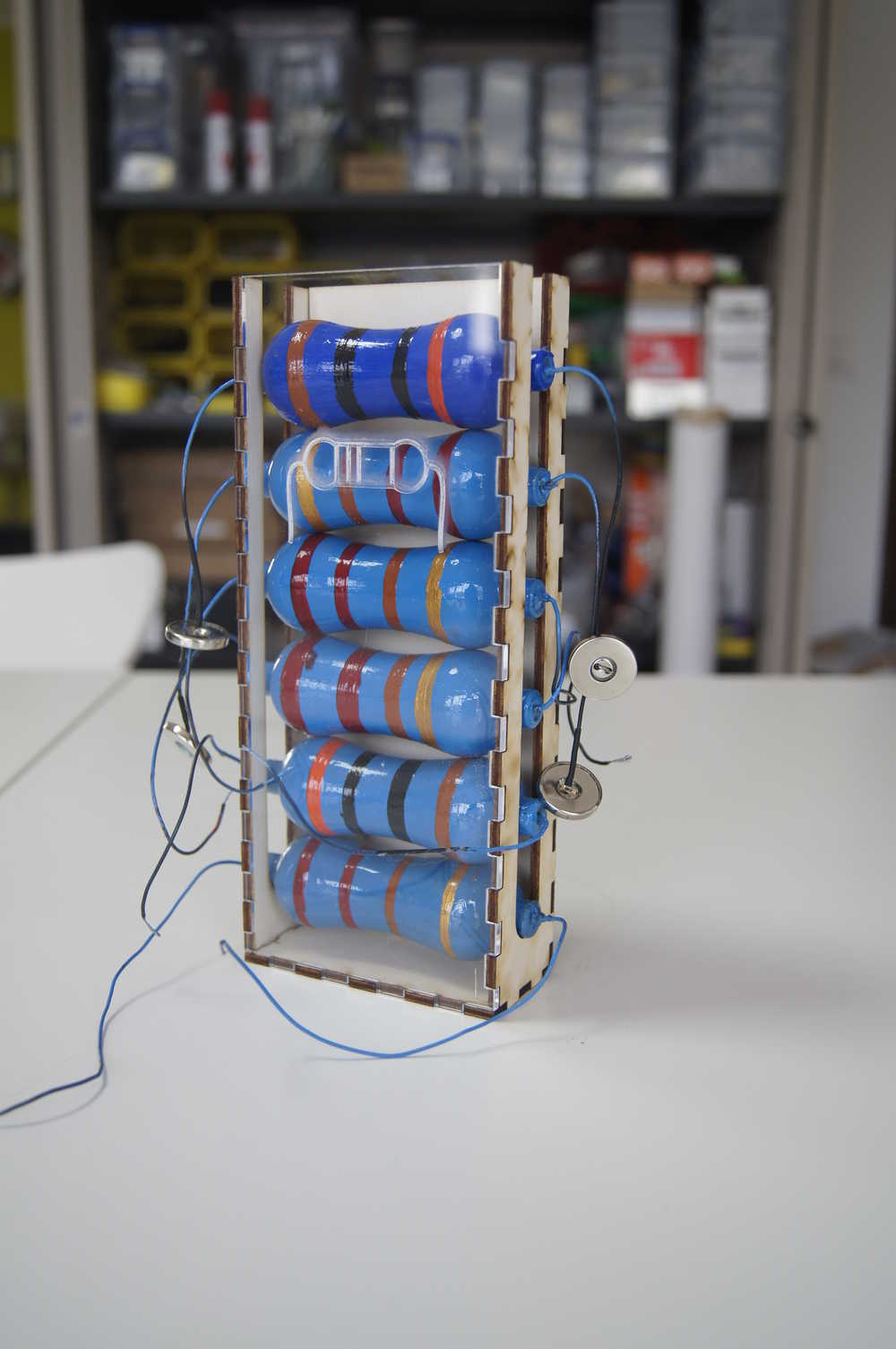 The boxmaker adapted by the Ingegno MakerSpace
The giant LED's
To top
Manuals and files
Giant resistor
Giant LED Jumperwires Box for giant resistors