-
Prototypes and testing
Preparation tools
Making the hardware
Assembly instructions
Technical details kids giant breadboard
Manuals and files
Prototypes and testing
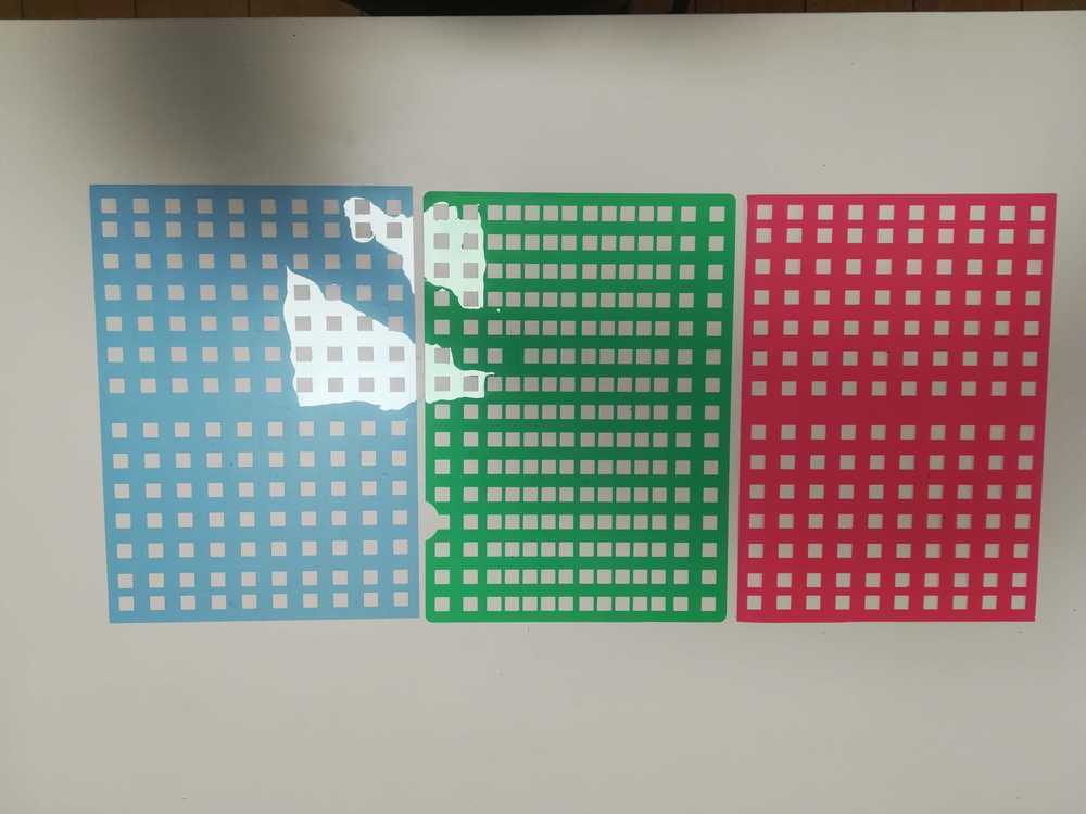
Of course the breadboards need to be made out of a strong material that can be stacked. For the breadboard of the kids there is no need to have them flexible as they are A4 sided and fit
perfectly within a box. All the boxes that we use in the lab are or from Really usefull box or the samla boxes form Ikea. We use those two brands because they
have very strong boxes that are also see through.
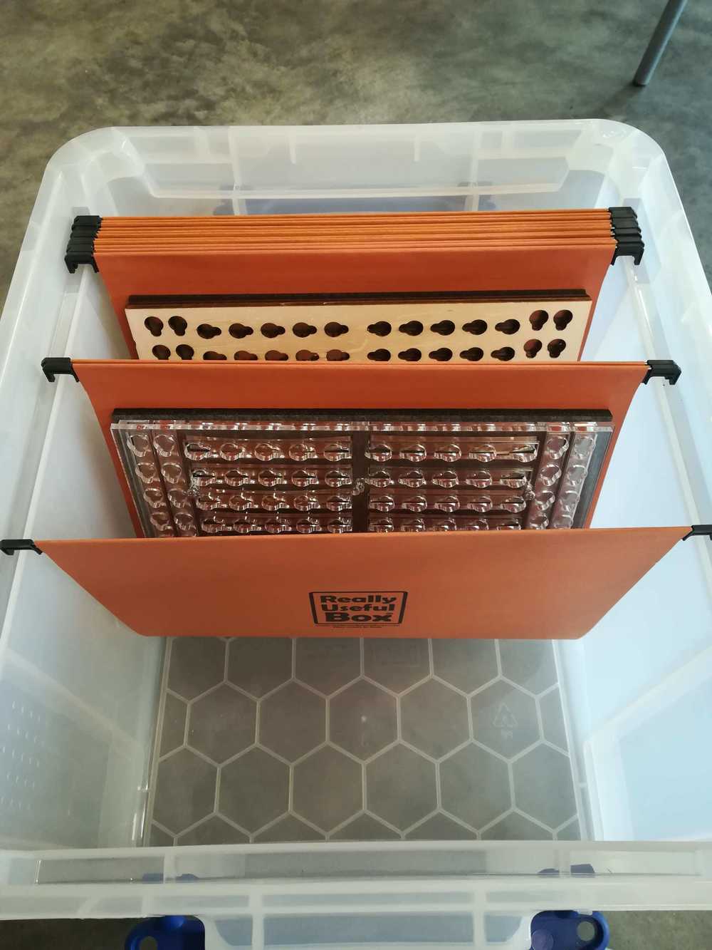 The box that we will use to transport the breadboards for kids.
First prototype
The first time that I took a look at the possibility of making a giant breadboard was when I was an intern at Ingegno back in 2016. I already lasercutted a base but never developed it futher. Back then however, I was still convinced that the board should look like an actual breadboard.
 The first prototype lasercutted in 2016
Second prototype
During the conductivity tests I came up with a prototype that has an open wooden middle layer and a plastic top layer to see the little holes. As described within the chapter of materials, we found out that the magnets would be attracted to each other and that we needed more space between them.
 Test with conductive ink. The LED is not burning bright due to a to high resistance
If you cover up the connections, they kids once again loose track of the connector lines within the breadboard. The solution for that is or opening up an existing breadboard and showing this to the kids. But that is what we do now and it only has a select impact on the children. We really wanted to bring the breadboard to them and let them experience the connections. Seeing the wires, combined with how we explain conductivity, might be the solution.
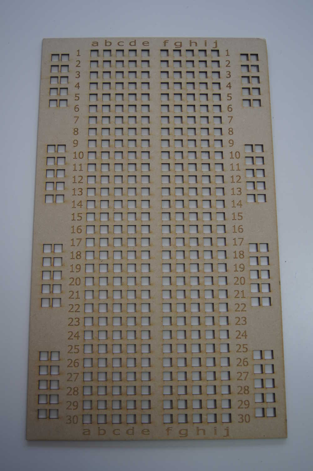
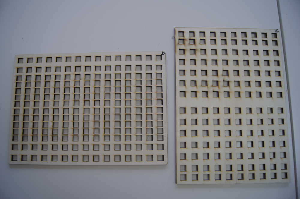
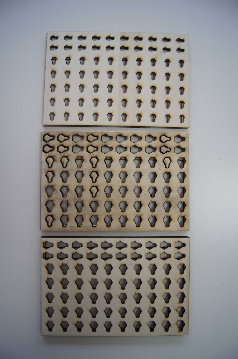
I started with a drawing in Inkscape, the same that I've been working on for the other parts of the breadboard. The outlines stayed the same, but the inside changed, because in this case I only needed the small holes.
As for materials, we chose to use normal charts in which you can put paper. Sadly, the material wasn't specified further than just 'plastic'. I still need to find time to do the burning tests to determine if the plastic is actually ABS or PVC. But for now I went with putting the material in the vinyl cutter and cutting it that way.
Interesting to see was that not every color cuts the same. Blue and red were the best and easiest to cut, green and yellow were a mess.
Third prototype
Keeping material cost and time in mind, I started making a smaller prototype to test out all of our options. The results came in pretty fast to: use stronger magnets and get enough magnetism from the back layer was the conclusion on the condutive part, but on the part of the hardware, we needed little walls in beteen.
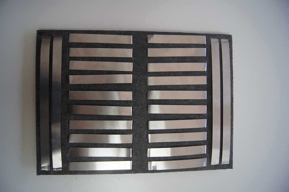
In the picture below you can see a test that we conducted with small steel strips, filt, PVC plastic to show the holes, magnets and wires.We didn't connect the wires the right way as we were just testing the connectivity and resistance at that moment.
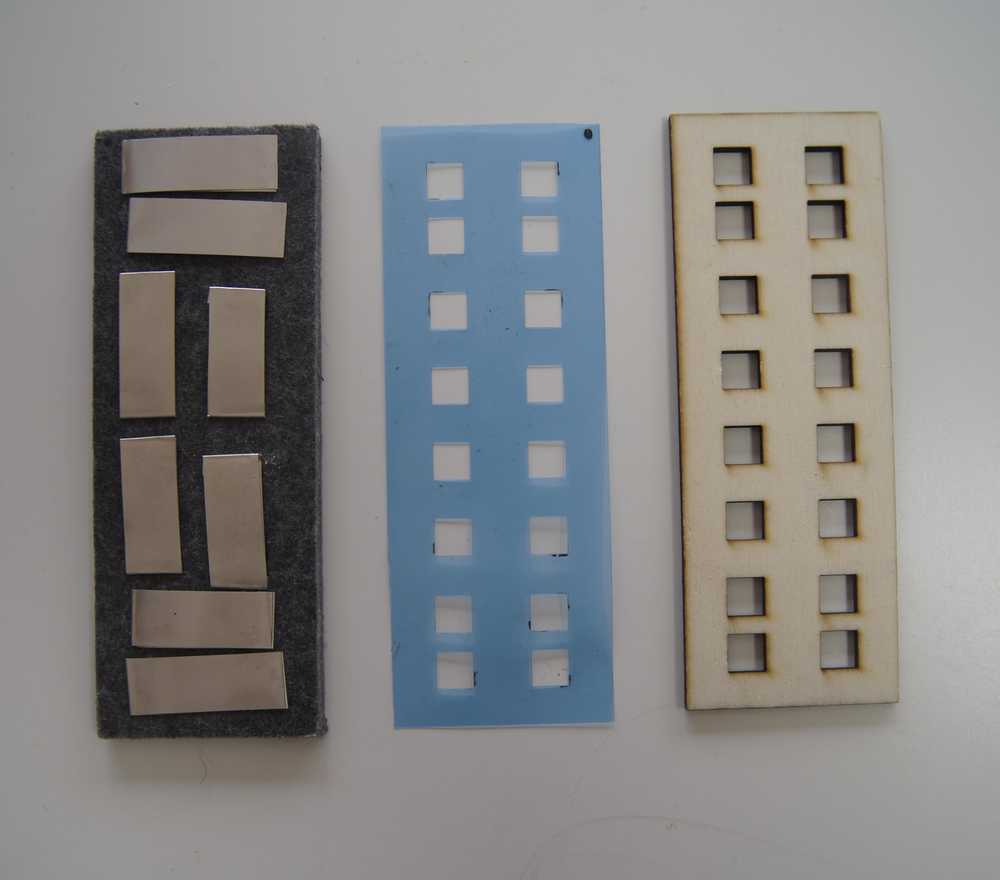 A test with small metal strips
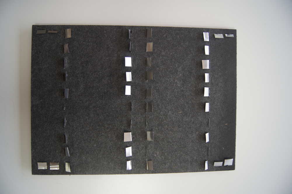
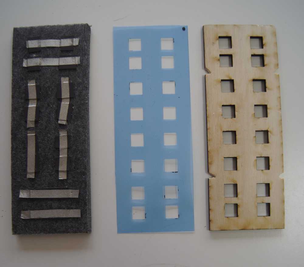 A test with spacetape (silver textile) and magnets
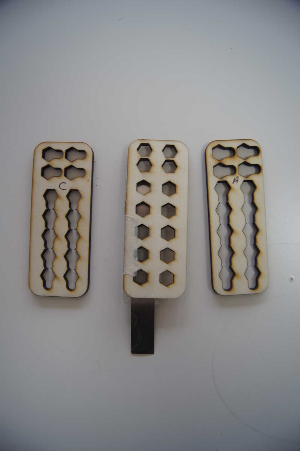
Another thing that needed to be tested was the size of the holes. I made some samples and asked the kids in the lab wich one they prefered. We settled on the 2 biggest ones.
My biggest mistake during the tests? Soldering the magnets to the wire. They can be soldered, but you need a very specific technique for it - that I eventually learned. When heathing up a magnet, it loosed a part of their magnetic force. The new problem assignment for the jumper wires would be this: How to connect wires to the magnets without soldering or glue?
First production
As the Easter holidays were coming closer, it was also time for a first test. But before I could do my testing on unknown children, I needed to start a small production. We decided to go for the two options described above and see what happens when using them. Within the team, there were however discussions on how the breadboard should look like. Should it be held horizontal, or should it be held vertical?
We decided to test both with the children. And it was devastating!
During the tests on your first mini breadboard we learned that the magnetism isn't always going down. So we needed to find a way to keep the magnets and jumper wires separated - as we already knew, but it was not enough. We set a step back to the first A4 prototype that I made and changed the drawing a bit so that it would fit the new layout. It turned out to be a hit. The magnets stayed separated from each other.
The reason why we did a user test was to define if the kids could:
- Work better with the breadboard
- Understand better how the board works
- Still have fun
- the system we have now is a good system
- The magnets are strong enough
- The materials hold the abuse of children
There are two main conclusions to take after this first stage. First of all: working with magnets will be harder than anticipated. Second the production process needs to be optimized.
The magnets and magnetic part of the breadboard already got explained a bit before. But here is a recap: find another solution! (for the small boards)
What we didn't talk about yet is the time it takes to produce the breadboards. Machining time is always being counted differently for me. You might need the laser for an hour, or the 3D printer, but you can do other things while waiting. But during the assembly, you need to be focused on just that. Some notes of attention:
- Check the colour of the plastic. Some plastic cuts better than other. This gives you less or more work
- Check the static electricity on the plastic. The green plastic was a mess as it got stuck to everything due to static electricity. The other colours however (escpecially red and blue), just poped out.
- Lasercut the filt and put markings on where the conductive/magnetic parts need to come. This time I always put some lines on the filt to see where I had to put my pieces, but its not completely exact. It will save time later on to not having to recheck everything if they are lying good.
- Use a different adhesive for the steel strips.
- Optimize the whole cutting process of steel trips, magnets and conductive textile See what you can lasercut or make a mold. This will also help if all the pieces are the exact same size.
- In the landscape models, create some more space for the underlying lines.
To top
Fourth prototype
We left the breadboards for what the were and took time to rethink the whole process of the breadboards, the materials and workflow. One of the problems that we had during the test was that the metal strips got loose. In this version it was still ment for the boards to be assembled and disassembled so that the children can see the wires. But it just ain't made for that. One solution was to bend over the metal strips in an U shape.
 The front of the breadboard
 The back of the breadboard
As you can see, the back of the breadboard isn't exactly safe. But I didn't want to put an extra layer onto it. So I needed another solution. I tried to ply the leftovers with a plier, but that was no solution, especially not to the middle parts.
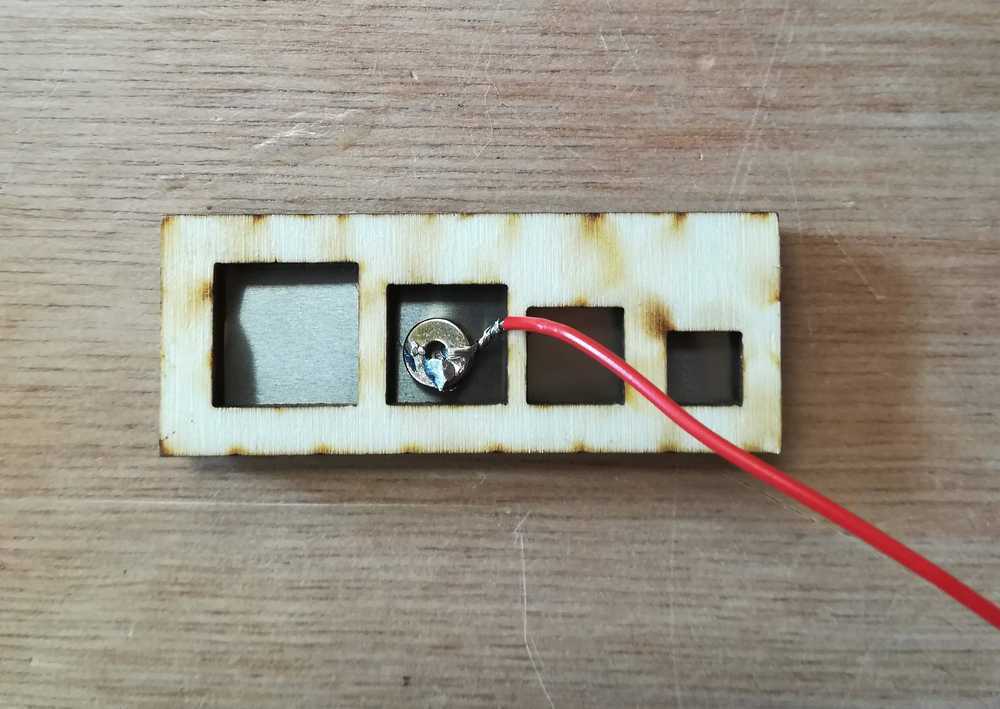
Next to that we had to solve the problem of the jumper wires. I went testing again but on smaller parts. At first I went back to how the normal breadboards look. What if we push the head of a bolt into a designed hole and connect like this? It worked, but was also very hard for the connection to stay put, put it into the hole (no freedom of shape and movement) and it would be to hard for the children. I went on with smaller experiments where I could move the head of the bolt so that it would lock and secure the connection. The problem there was that all the lines
 Testing tolerances and shape.
As I noticed that taking the shape of the bold might not be ideal. So I did some more tests. Another thing that came out, was the thickness of the wood. You need to keep this in mind, together with the height of the bolt head. The plan was to work with M3 or M4 bolts, but because of the wood thickness, it had to change to M6 bolts.
 Testing sizes and alignment of the bolts.
 A more rounded shape next to the shape of the bolts.
 A more rounded shape.
The final prototype makes use of the more rounded forms as the children don't have to look as closely on how to put the bolt in, and can concentrate on making their circuit.
Prototype 5
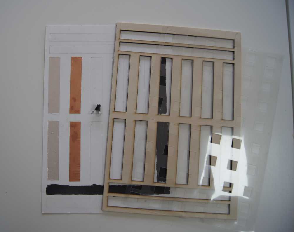
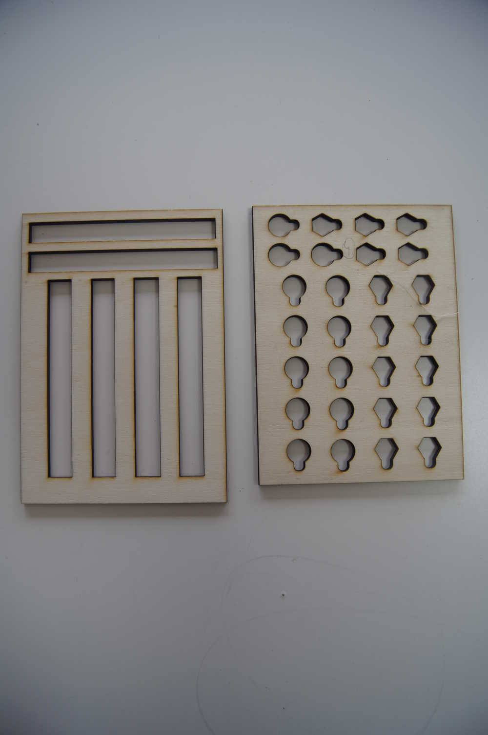
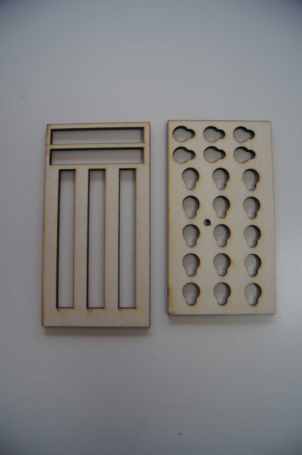
Once the top layers were finished, I also needed to develop the bottom plate. I already had a plate, that I kept reusing from the first prototypes, but some small changes were made later on. For example, the connectors to keep all the layers in place were lasered into the industrial filt. I made some errors in size and had to retry a few times. The first plate that I used as also made by hand. I cutted out all the little lines where the metal plates had to come, but as mentioned before: the process needed to be optimized. Therefore I rechecked my file for the bottom plate (wich I never used before).
Of course, nothing goes without at few mistakes and I learned that the lines where the metal wires come were to small for the actual metal wires. In the end I had a file wich was perfect for the filt, but as I would learn later, not for the wood.
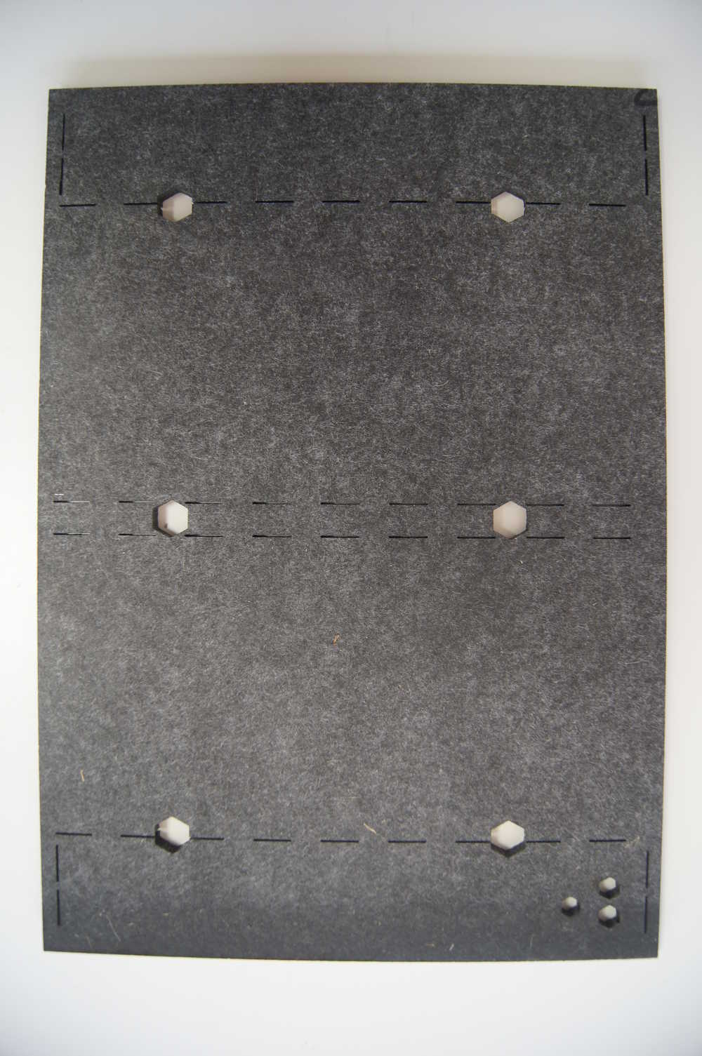 The lasercutted filt
Preparation tools
In case of automatizing the process of making the breadboards for children, I needed to find a faster way for assembly and having the parts cut correctly. A tool that I developed was a mold to bend the pieces with straight corners.
Tool: the wirebender
One of the problems with the metal plates is making 90 degree corners. They always want to jump back a bit and if you bend them by hand, they are never really good and the same. To solve this I designed a mold for the smaller plates, as I need the most of those to make the breadboard.
I started with defining what movements I would need in my mold and what the best way would be to do this. I ended up with 3 movements.
- movement 1: keep the plate fixed
- movement 2: bend left corner
- movement 3: bend right corner
I designed and prepared my files in Inkscape, where I defined my base plate, all the sliders and bolt sizes. During the first tests I noticed that 4mm would not be high enough. I also noticed that there was a gap between the fixed block on the board and the right slider. I went back to Inkscape and did some minor changes in the file.
During the second test all went pretty well, and I decided to go with this version. Assembly instructions and manual can be found here below and files can be found at the bottom of the page.
The assembly of the mold

To top
Making the hardware
Final presentation prototype
At one point you need to stop developing and be happy with what you have. At one time during the academy exactly this happend with this breadboard to. We knew it worked perfectly on 4mm poplar (top and middle layer). It was time to move on to other parts of the assignment. One thing that I changed back then, was using a plexi top and middle layer.
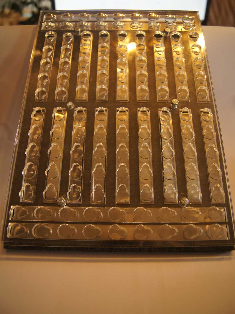 Hero shot of the final breadboard
Post final presentation development
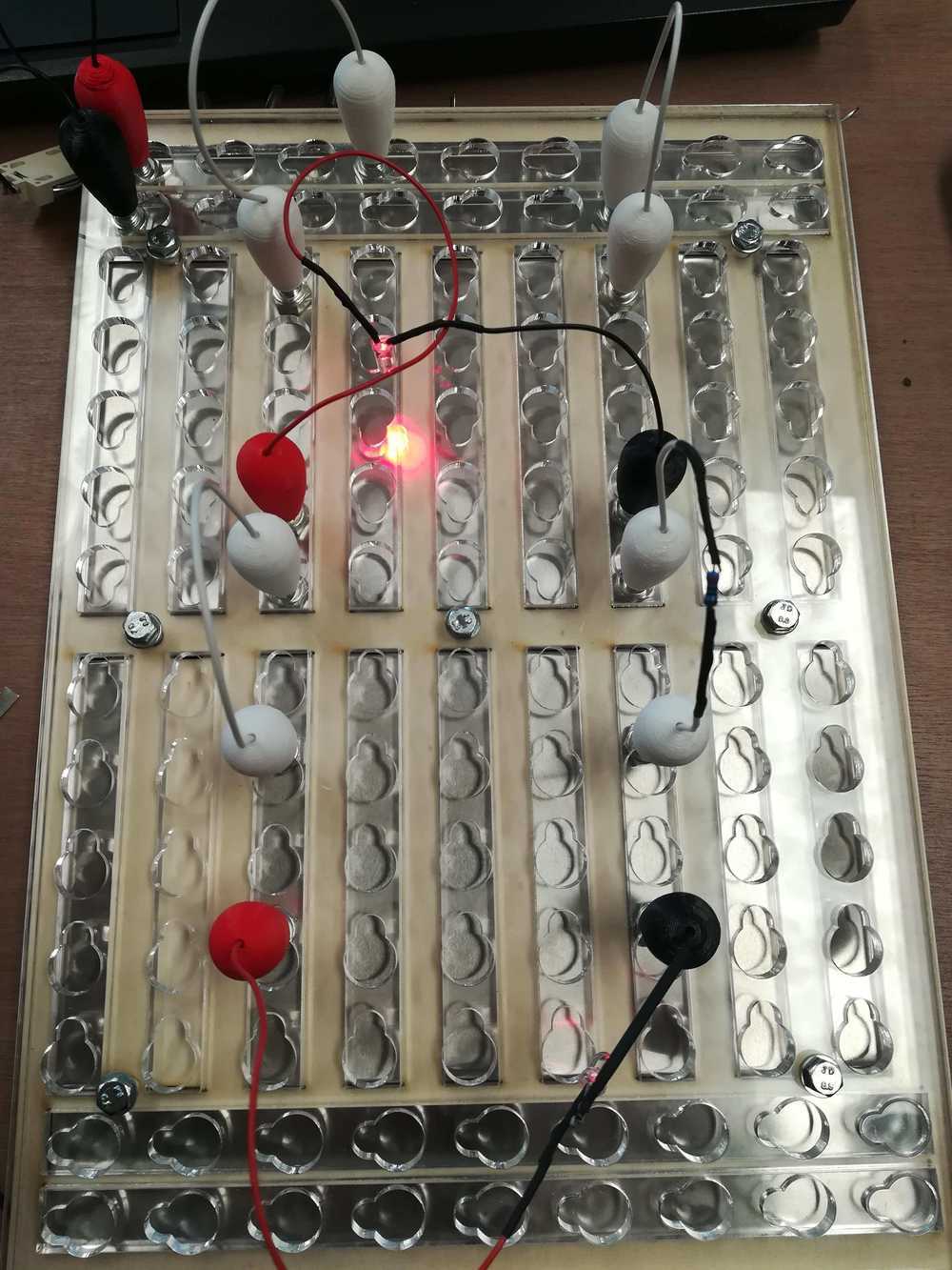
When the last prototype was finished (the plexi one) we decided to develop and produce those for the children in our lab.
some adaptations that we did since the final presentation was to add more connectors on the board and change how the layers connect. The trip from the Ingegno Makerspace to ULB, to home
in the car, on the train already took its damage on the board. We decided to let the bolts go all the way through and add more bolts as connectors.
A second thing that changed was the bottom layer. Getting the files from the final presentation prototype into production ment using all the 6mm industrial filt that I had. As there is nothing left, I switched to poplar wood as base. One of the problems that I encountered there was that the little lines made for the metal strips are to small now. The filt melts away, leaving a bigger hole than drawn. In wood this is much less. So be careful when lasering that you take the right file for the bottom plate!
 Test with conductive ink. The LED is not burning bright due to a to high resistance
To top
Assembly instructions
Bending the metal plates
 Bend the metal plates so that they fit easily into the base plate.
Adding the metal plates to the base
 Add the metal plates to the wooden or filt base plate
Assembly of the base plates
 Assembly of the boards. Notice to turn the bolts around!
To top
Technical details kids giant breadboard
Exploded view
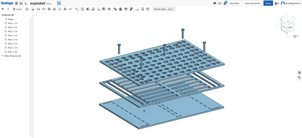 Exploded view of the main parts of the kids bread boards
Bill of materials
For 6 kids breadboards
| What | Amount | Material | price | Buy |
| bases | 1 per plate | wood | ||
| bolts | 30 (5 per board) | metal | ||
| nuts | 30 (5 per board) | metal | ||
| plexi | 6 (2 halves per board | plexi | ||
| metal strips | 3 rolls | metal | €10.61 | Dymowinkel |
Manuals and files
Preparation
-
File lasercut files for making the bending mold.
Stop motion for assembly of the mold
Stop motion for bending the metal wires
Stop motion for assembly for the base board
Files for the small breadboard