
Week 7: Electronics Design
Assignments
☑ Use test equipment in your lab to observe the operation of your circuit board
☑ Use a Software to Design you PCB
☑ Make your PCB
☑ Extra::Program your PCB
BRAINSTORMING
Softwares
 Eagle - Autodesk software for designing circuit boards, connects with Fusion360.
 Arduino - Software for easy code writing and uploading
Use test equipment in your lab to observe the operation of your circuit board
Multimeter
A multimeter is a device that can measure a variety of electrical quantities. It has a numeric display screen. It measures voltage, current, resistance, and electrical continuity.
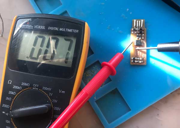 There are three parts to a multimeter:
 Prod your prodes on the board on traces that should connect. It beeps if a complete path is detected. I the path is broken, or something is off, the DMM will not beep. You can learn more about using multimeter [HERE]
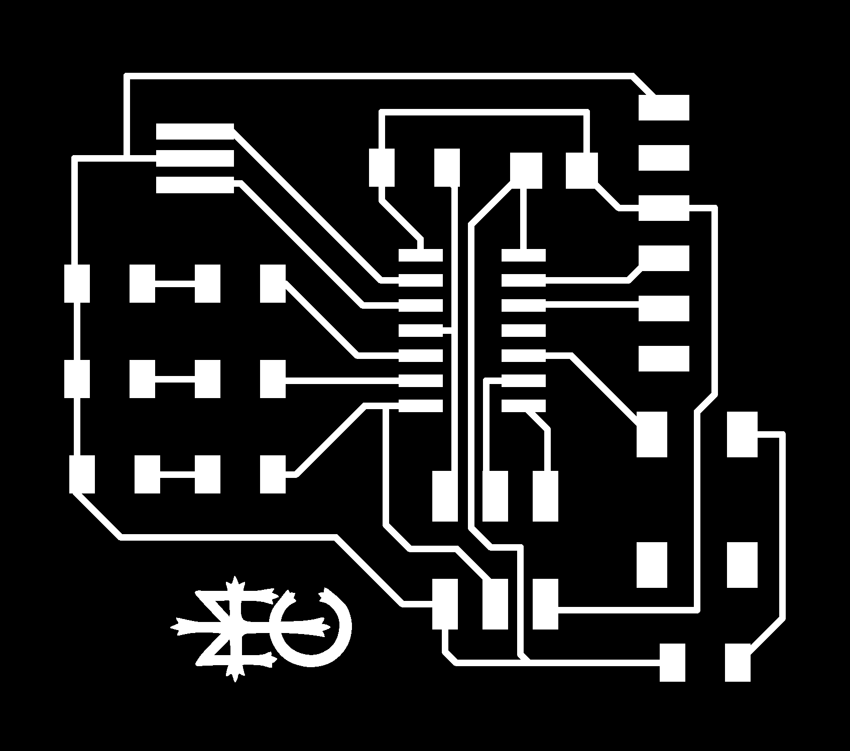
Design your PCB
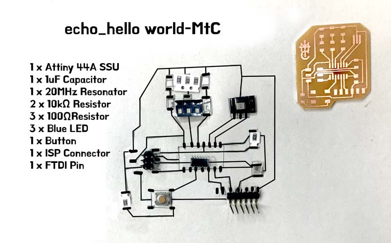
For This week, our assignment was to make an Echo board using
Attiny44 with at least one LED and one button
IF you need it, you can get help from the Fab Archive Tutorials on downloading, Eagle, and the fab library for components.
The Fablibrary is very important because it has the precise design of components that we will need to design our assignment boards.The fab library is always being updated for the use of Fab students!
Check my Download links for the library.
**If you try clicking the link on mine, or the Fab archive page, you will be taken to the Fab github page with over 3500 lines of codes. It can seem daunting at first, but all you need to do is go back, right click on the link and "save link as" and save the library in your Eagle library folder.
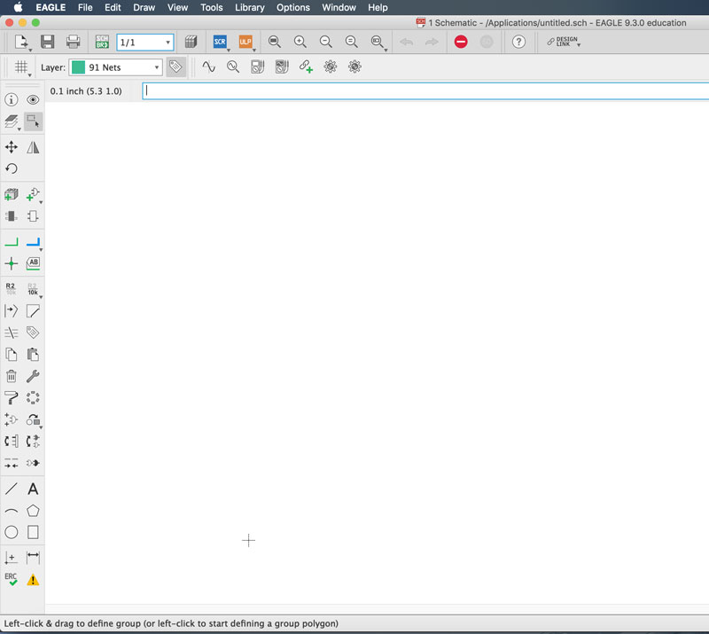
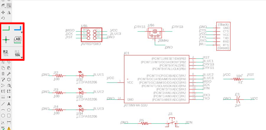
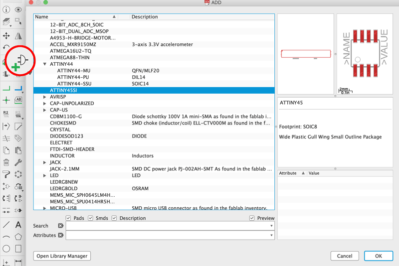 Add Components by clicking "add part" from the tool bar on the left.
That will open your library. Click on the component from the list and place them.
You can place multiple of the same components. You can stop by pressing "ESC".
The Software will take you back to the library, so that you can continue with other components.
You can stop by pressing "ESC" again
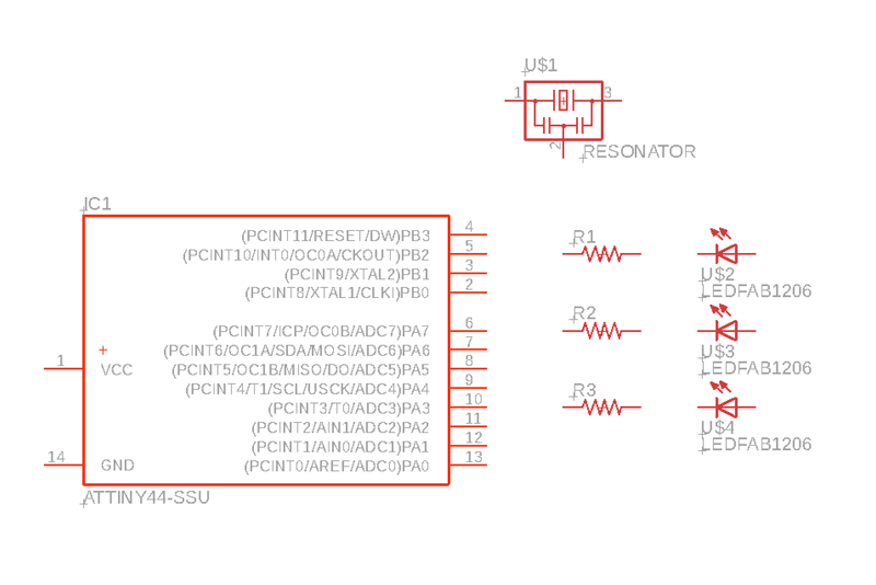 Once you've placed all your components. You can still move them around, and arrange them.
 you can turn the components around by right-clicking.
 Next, we can make the circuits. Using the line making, "NET"(green line) you can connect the components.
!! The tip I got from my instructor was instead of spending time trying to connect each one, give names to the connections with "LABEL" and it will ask you if you want to connect the lines with corresponding names.

 If you have finished making the connections,
click on the button on top tool line that generates/switches to board. It will generate and take you to your board.
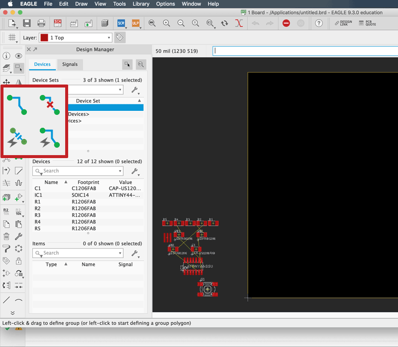 When you move to your board window, all the components are initially at the bottom left corner
You can select and move them around to organize them and connenct them like in the Schematics.
There are other ways like "Autorouter" which automatically connects them, but it is not always reliable.
!! You can adjust the width of your route, as well as the type of connection, the bend types and grid for movement flow from the tools in the upper bar.
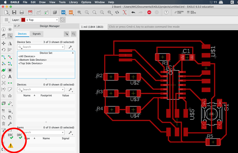
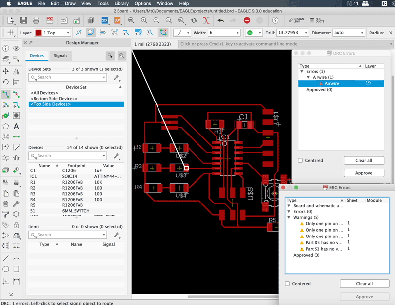 Check your ERC and DRC (electrical Rule and Design Rule Check)
If you have errors that pop up, fix them. and export you file.
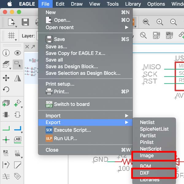
You have choices of exports I was advised to export as image. But I had trouble with the size in the process of making adjustments and resaving from Illustrator (needed to do that to make the cut file). Everything worked fine when I exported as dxf file, it keeps the paths and the setting for keeping the original size make sure that the size is the same. You can make adjustments, make the cut file and save them all as png to use in fabmodules.
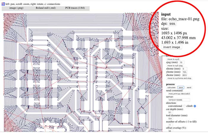
Check your image size and the mill path to make sure that the traces are all cut well and that there are no glitches.
Make your PCB
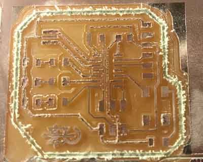
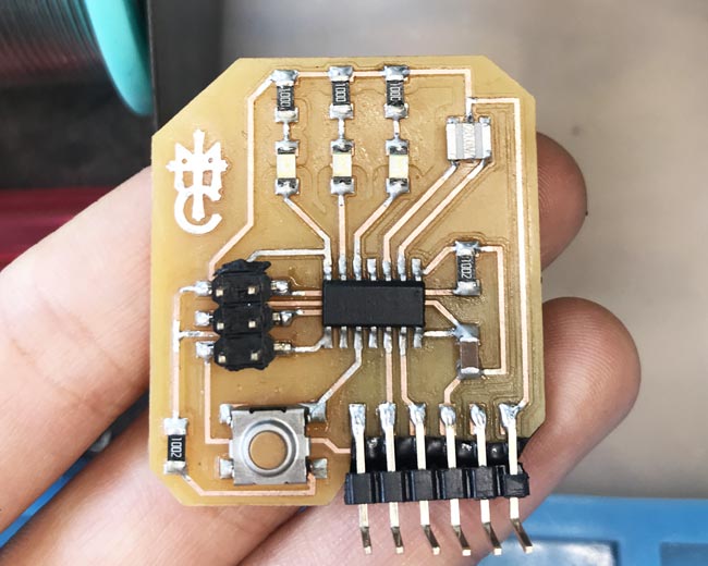
There were some complications when it was milling. The copper board that was taped on the bed had popped up a little while it was milling. So I had to pause the process every now and then to push it back down. Because of this, there were some areas that are cut a little bit deeper than the rest. But it didn't cause too much problem.
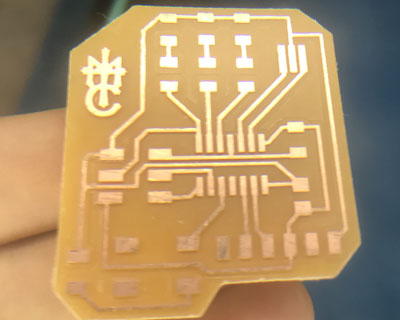
When it is done, you can see that the traces are not very clean. you can clean your
I had to pause here for a bit because I needed to figure out the resistor for the LEDs and for the Button. I got help from [Sparkfun] about that.
I used blue LEDs because I didn't like the other colors (I would have used purple if we had any, but we didn't so I stuck to blue). We were told to try a design with three LEDs so that we could practice with something a little more complicated.
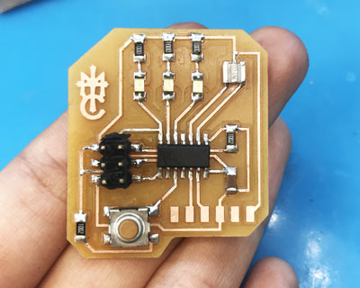
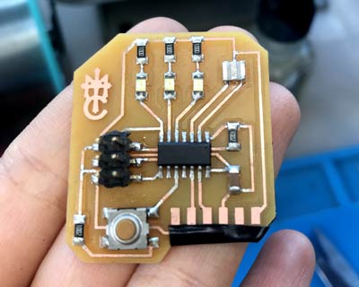
The FTDI connector part was tricky because I had a trace going below it. So as a precaution I put electric tape over the trace and put the connector over it.
EXTRA
Now to Programming
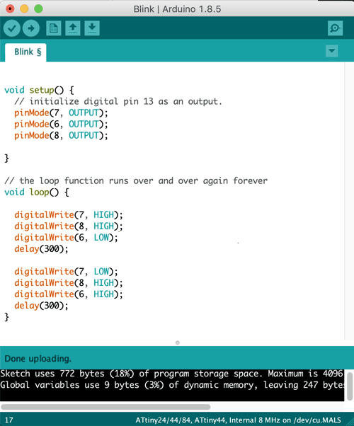
I followed the instructions from [high-low tech]. make sure to follow closely on the arduino settings for the correct Microcontroller.