Rodrigo says...

Don't give up!!!

Links

Other student's doc about HM-05

A big help on connecting your HM10

about I2C

Download

Datasheet about HM-10

ESP8266 Arduino Code

My Master Code

My Slave Code

TinyWireMaster

TinyWireSlave

Boulder Trace(Master)

Boulder Cut(Master)

Pebble Trace(slave)

Pebble Cut(slave)

...

Week 14: Networking & Communications

Assignment

BRAINSTORMING

What we are trying to do is...

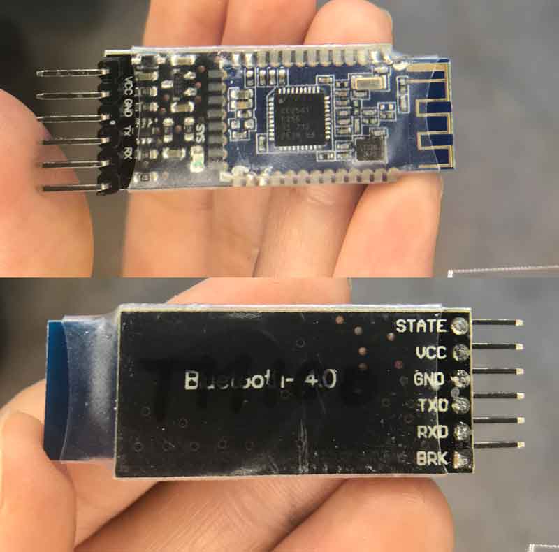
I was had taken a workshop class before using HM-10. I wanted to recycle it.

The circuit is so simple and small , there is only few connection to be made Arduino Pins Bluetooth Pins RX (Pin 0) ———-> TX TX (Pin 1) ———-> RX 5V ———-> VCC GND ———-> GND

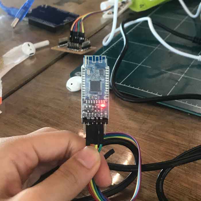
Connect your bluetooth to the FTDI serial.
Once it is connected properly, the red LED on the module will start blinking.
and it will stay solid when the connection is made to a device.

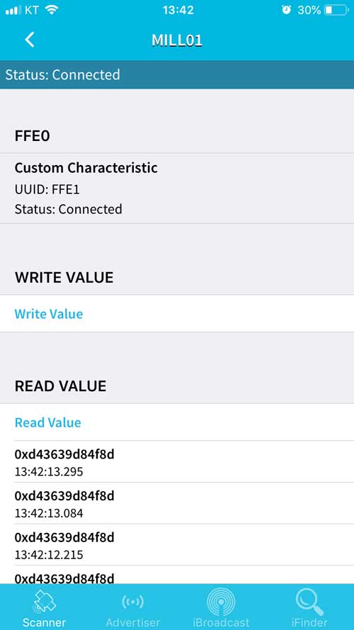
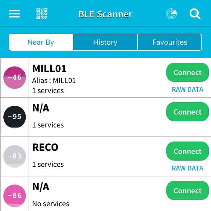
Go to the App store and download [BLE Scanner]

Your Bluetooth should pop up on your scanner.
Default name is [HMSoft]
(Mine pops up as Mill01 because I changed the name)

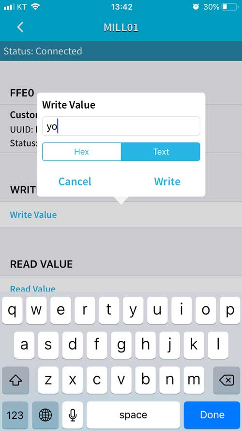
Write your text and press the [Write] button.

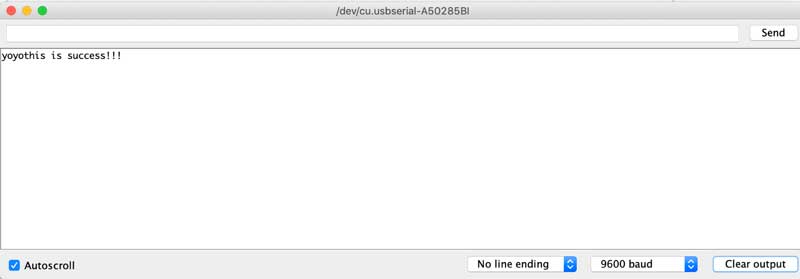
Your Serial Monitor should be able to read and communicate
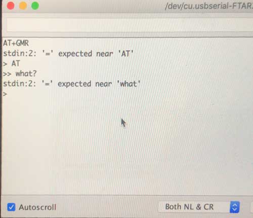
Getting an Arduino talking to the HM-10
Next we will connect the HM-10 to an Arduino and try basic serial communication and AT commands.
**Note: AT commands only work when the HM-10 is not connected.
After a connection is made the commands are treated as data.
“AT” is the exception, the “AT” command breaks the connection.

Circuit
Connect the modules as per the following:
– HM-10 TX pin to Arduino D8
– HM-10 RX pin to a voltage divider and then to Arduino D9*
– HM-10 GND to GND
– HM-10 VCC to +5V

Common AT commands Here is a list of the main AT commands. Remember that commands should be in uppercase and not include line ending characters (\r\n) unless you are using the above sketch in which case it does not matter if you include line end characters or not. AT Test Command or Disconnect Command If the module is not connected to a remote device it will reply: “OK” If the module has a connection then the connection will be closed. If the notification setting is active, the module will reply with “OK+LOST” AT+NAME? Query the name Returns the name the module broadcasts such as HMsoft. AT+NAMEnewname Change the name of the module Changes the name broadcast by the module. For example: [AT+NAMEmyBTmodule] changes the name to myBTmodule. The maximum length for a new name is 12 characters. AT+ADDR? Queries the HM-10s mac address Returns the address as a 12 digit hexidecimal number. For example: OK+ADDR:606405D138A3 AT+VERS? AT+VERR? Queries the firmware version number For example: HMSoft V540 AT+RESET Restarts the module. Returns OK+RESET Will close an active connection while restarting. AT+RENEW Restores the default factory settings. A quick and easy way to reset all settings. AT+BAUD? Query the baud rate used for UART serial communication. This is the speed a host device like an Arduino uses to talk to the BT module. It is not the the speed used to send wireless signals between different modules. Returns the value 0-8, For example: OK+Get:0 0 – 9600 1 – 19200 2 – 38400 3 – 57600 4 – 115200 5 – 4800 6 – 2400 7 – 1200 8 – 230400 The default setting is 0 – 9600. Remember that both devices, the Arduino and the HM-10 need to use the same baud rate. Garbage characters are usually a sign of mismatched baud rates. AT+NOTI Set the notification status If notifications are turned on, the HM-10 will reply to commands with a confirmation message or send out a message when certain events take place, like “OK” for the AT command and “OK+LOST” when a connection is broken. AT+NOTI0 – turn off notifications AT+NOTI1 – turn on notifications AT+NOTI? Query the notification status Returns either 0 or 1: 0 – notifications are off 1 – notifications are on AT+PASS? Query the password used for pairing. Replies with a 6 digit number like “OK+Get:123456″ or whatever the current password is. AT+PASS Set a new password. The password must be 6 characters long. AT+PASS123456 Sets the new password to 123456

Design and Build your own

Networking was hard as it was but now I had to design, build, program on my own. great.

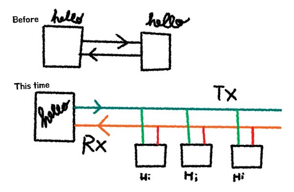
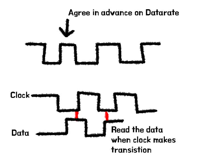
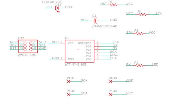
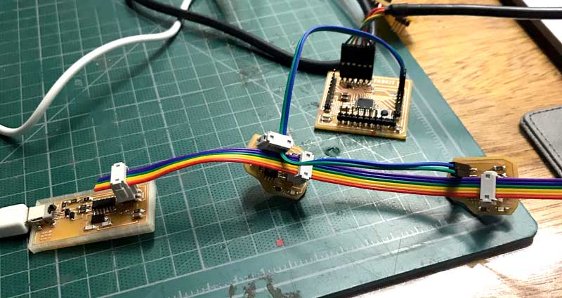
I decided to go for a simple one where I can learn and practice.
So I went for I2C bussing

The Inter-integrated Circuit (I2C) Protocol is a protocol intended to allow multiple "slave" digital integrated circuits ("chips") to communicate with one or more "master" chips. Like the Serial Peripheral Interface (SPI), it is only intended for short distance communications within a single device. Like Asynchronous Serial Interfaces (such as RS-232 or UARTs), it only requires two signal wires to exchange information. *source sparkfun (Pamela's website)


referring back to Niel's sketch, we need to bus.
...
but using I2C connection. It only requires 2 signal wires: a Clock pin and a Data pin.
which is simple compared to RS-232

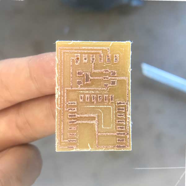
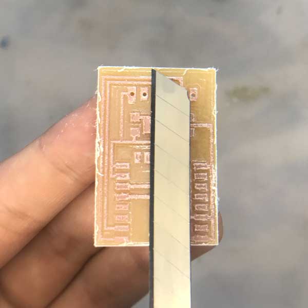
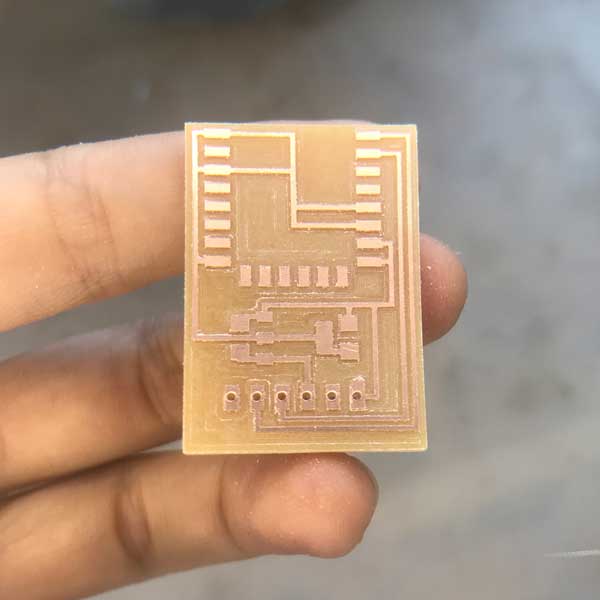
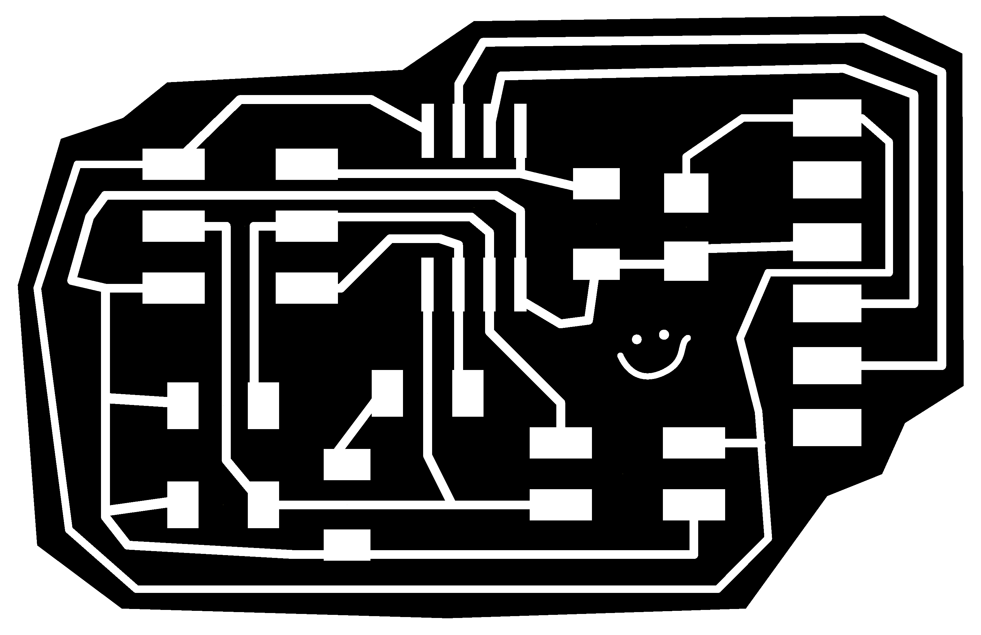
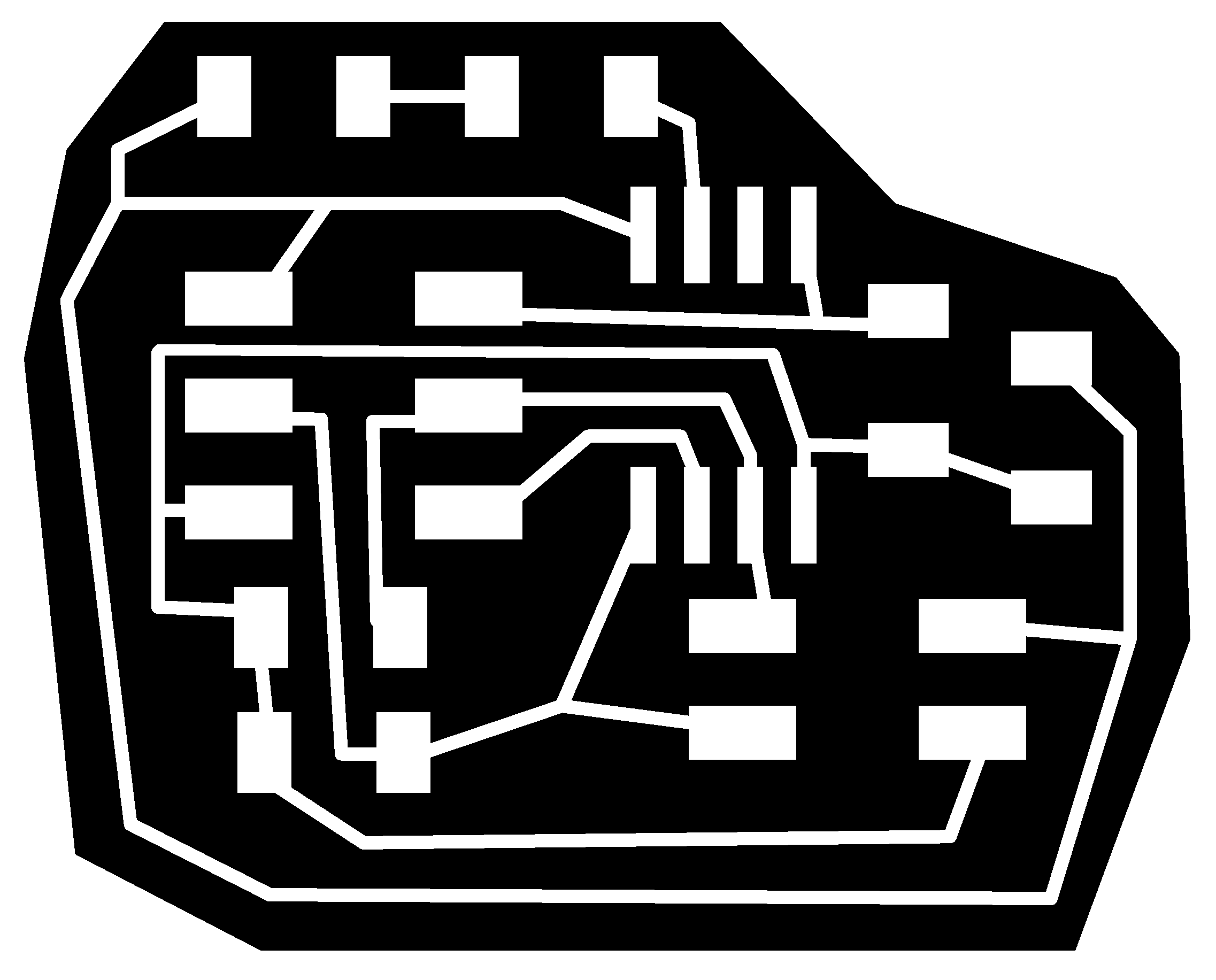
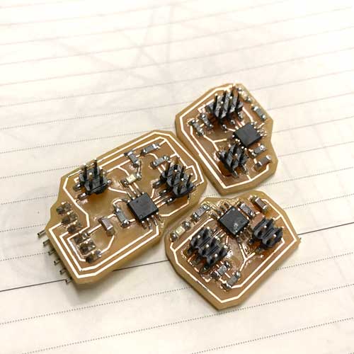
Using Niel's example board, I designed a small simple nodes and a bridge with LED.

Programming

First, you need to download TinyWire Libraries (Master and Slave) and put them in your Arduino Library (in the sidebar)
For some reason I could not get my code compiled for my Bridge to work like a Master, So I decided to use Wire.h library with my Fabkit. You need two different codes for the Master and the Slave.

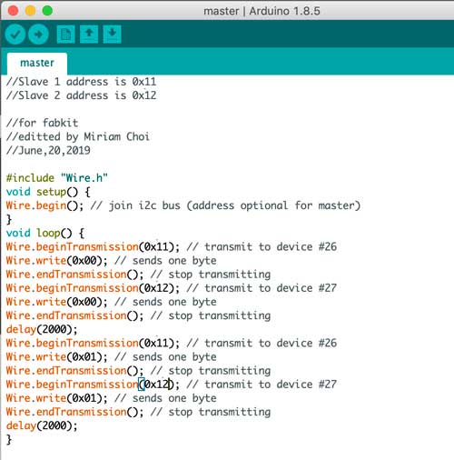
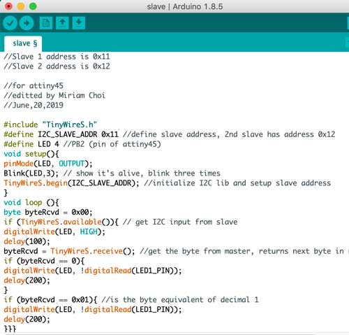
Loaded the codes into the corresponding PCB. Connect them, and hoped it works!
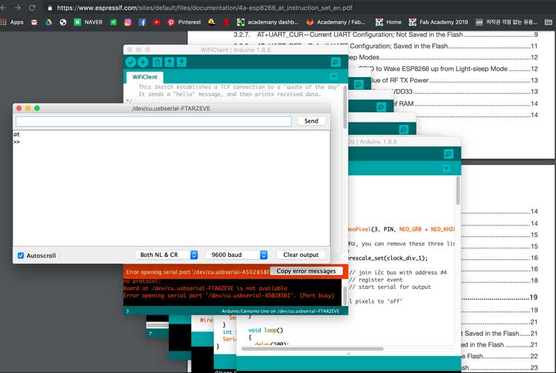
Trouble

Still don't understand fully, and I need to play around with the code more to make it work. 
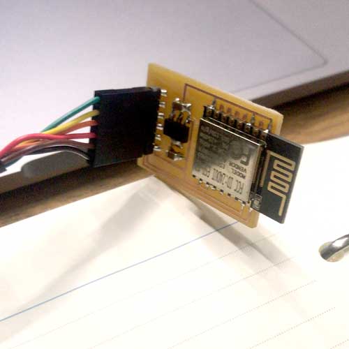
I was able to make a WiFi module using ESP8266,
and I tried to change some settings, but it was not very successful.