Assignment: Read a micro-controller data sheet. Program your board to do something, with as many different programming languages and programming environments as possible. For extra credit experiment with other architectures.
What Is an Embedded System?
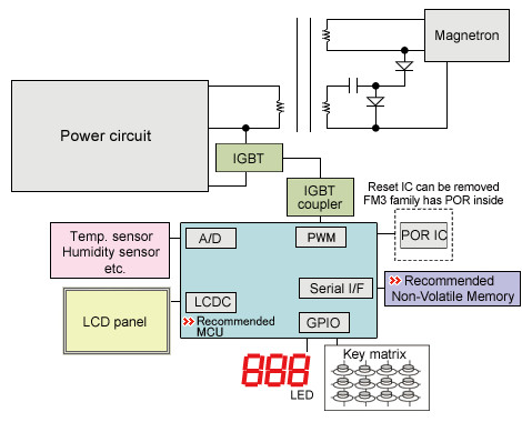
An embedded system is a combination of computer hardware and software—and perhaps additional parts, either mechanical or electronic—designed to perform a dedicated function. A good example is the microwave oven and tens of millions of them are used every day, but very few people realize that a computer processor and software are involved in the preparation of their lunch or dinner.
Group assignment
Compare the performance and development workflows for other architectures
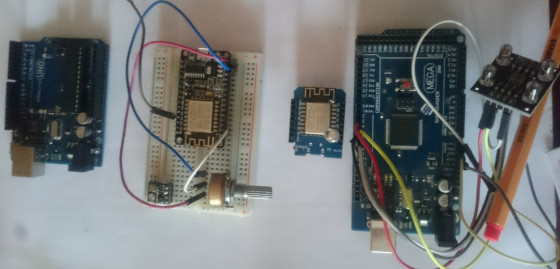
These are the different microcontroller boards we compared
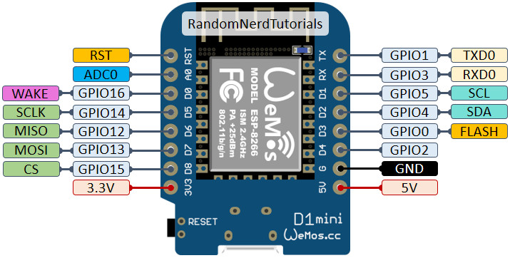
Wemos D1 Mini Technical Overview
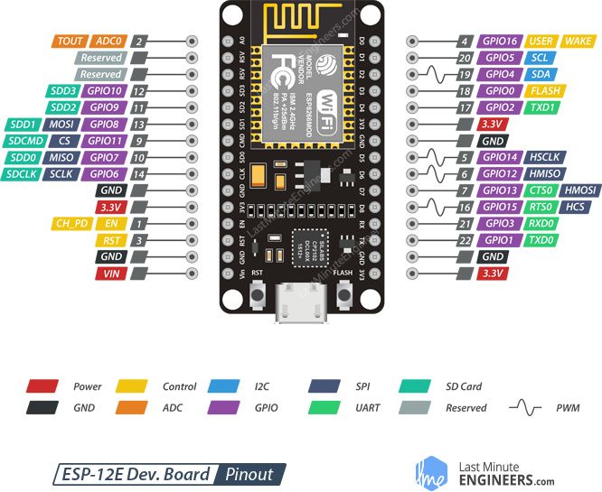
The D1 Mini is a 4MB flash controller based on the ESP8266 chip. It includes 11 digital input/output pins (I/O) each with an interrupt, PWM, I2C (except D0). There’s also 1 analog pin (A0). It’s compatible with Arduino, NodeMCU, and MicroPython. And, it also has a built-in Micro USB port, which you can use for power or to download programs.
Wemos D1 Mini & MicroPython
To understand the application of the python in the embedded system we used the following tutorial
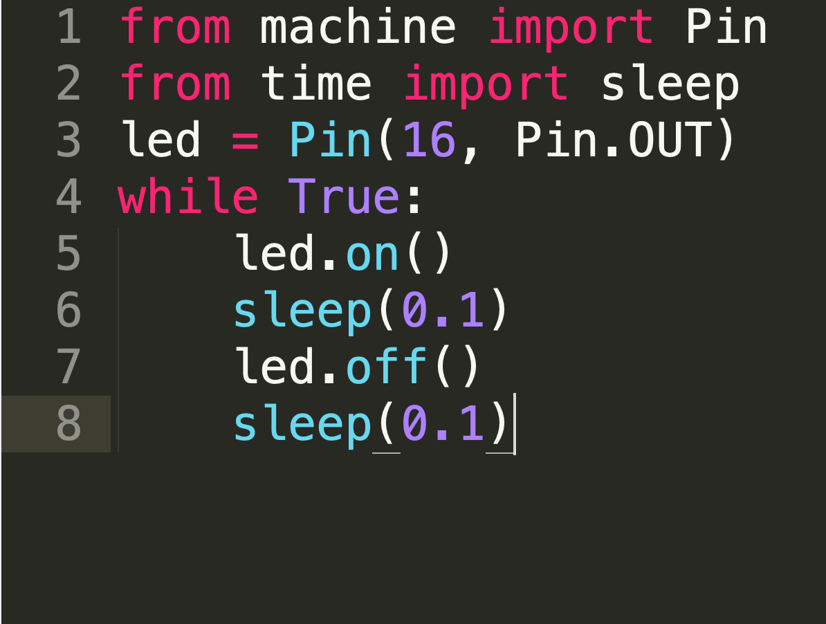
MicroPython’s goal is to make programming digital electronics as simple as possible, so it can be used by anyone. Currently, MicroPython is used by hobbyists, researchers, teachers, educators, and even in commercial products.
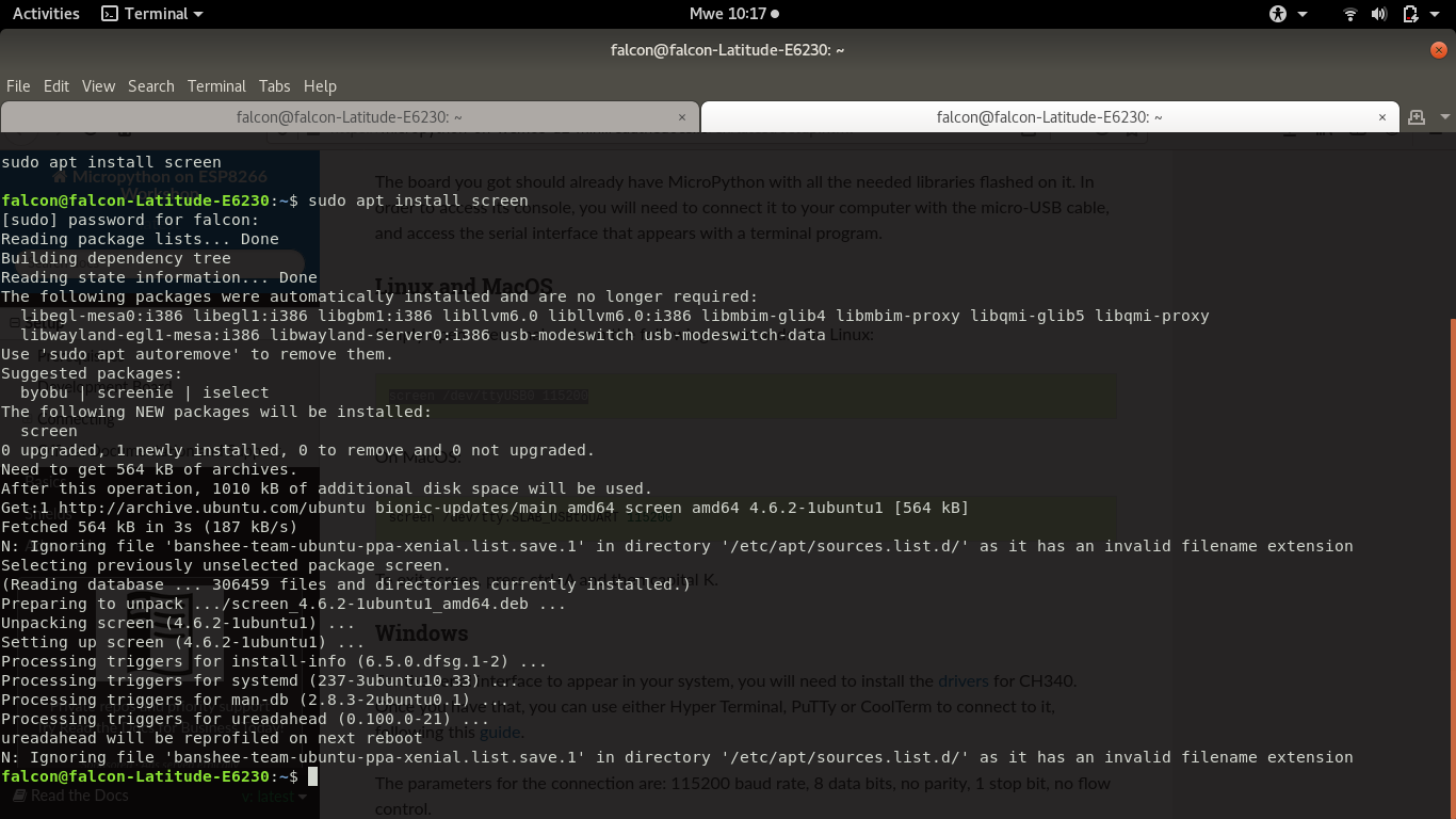
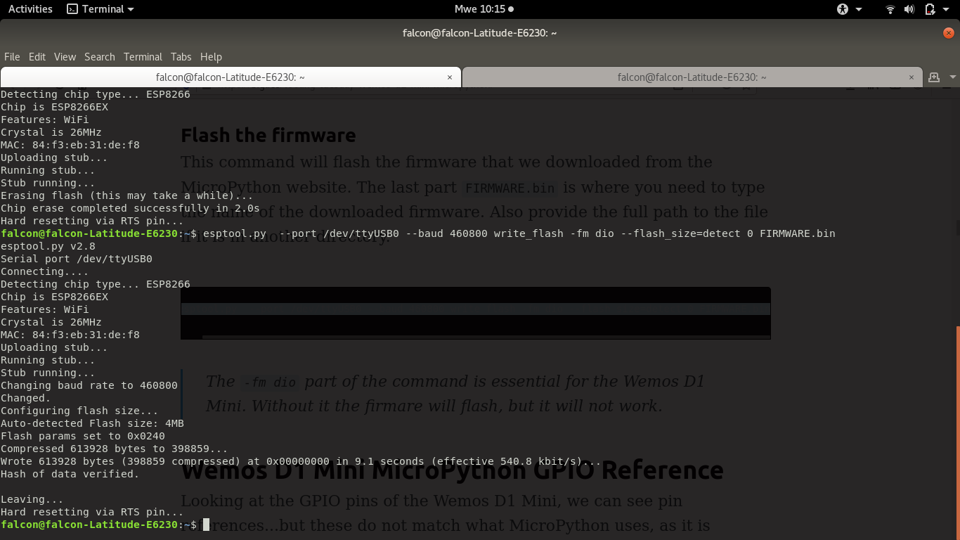
Before programming the board with micropython, we installed the farmware that can help us to upload python based file.

NodeMCU
The NodeMCU (otherwise known as the ESP8266) can run the familiar Arduino architecture. What makes it more versatile is the ability to program in Lua directly on the board. Combine this with onboard Wi-Fi and a similar pin layout to Arduino boards, and you can see why many consider these miniature microcontrollers to be a powerful alternative.
- Microcontroller: Tensilica 32-bit RISC CPU Xtensa LX106
- Operating Voltage: 3.3V
- Input Voltage: 7-12V
- Digital I/O Pins (DIO): 16
- Analog Input Pins (ADC): 1
- UARTs: 1
- SPIs: 1
- I2Cs: 1
- Flash Memory: 4 MB
- SRAM: 64 KB
- Clock Speed: 80 Mhz
- Wi-Fi: IEEE 802.11 b/g/n:
- Integrated TR switch, balun, LNA, power amplifier and matching network
- WEP or WPA/WPA2 authentication, or open networks
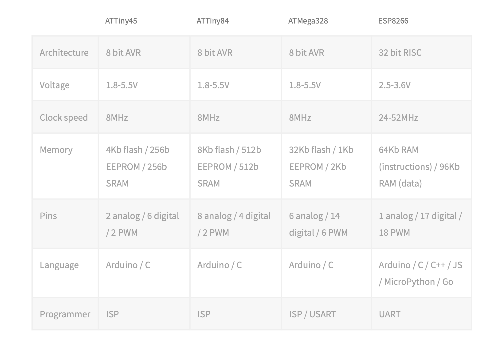
Here is a table comparing 4 different architectures:
Individual assignment
- Read a microcontroller data sheet.
- Program your board to do something, with as many different programming languages and programming environments as possible. 4
Read a Microcontroller Datasheet
A datasheet, data-sheet, or spec sheet is a document that summarizes the performance and other characteristics of a product, machine, component (e.g., an electronic component), material, a subsystem (e.g., a power supply) or software in sufficient detail that allows a buyer to understand what the product and a design engineer to understand the role of the component in the overall system. Therefore, I had a look at two datasheets of already used microcontrollers. One was The Atmel datasheet Attiny45 which is built as the microcontroller on the 'Fab-ISP' in assignment 4. The other one was the Atmel datasheet ESP12 (NODEMCU) which is used to implement the application & implication and the final project.ESP12 Datasheet
Attiny 45/85 Data-sheet Review
Literally, ATtiny85 is a scaled-down version of the Atmega microcontroller on Arduino boards with just a few I/Os (five usable pins) that can listen to or talk to most sensors and transducers. The CPU is based on RISC architecture and is mainly called low power controller that stands fit for the real-time applications that can operate on minimum power.Furthermore, they can be programmed in the Arduino IDE with the help of an Arduino board or through a cheap yet dedicated TinyAVR programmer. From the datasheet, we can see that it has an 8-MHz internal RC oscillator (which can be used as the default clock), 8 KB of flash, and 512 bytes of EEPROM and SRAM. We get two 8-bit timer/counters, one high-speed, with four pulse-width modulation (PWM) outputs total and a four-channel 10-bit ADC. Of course, there are some key features left off, such as I2C hardware, which would need to be enforced in software if indispensable. Attiny45 Datasheet
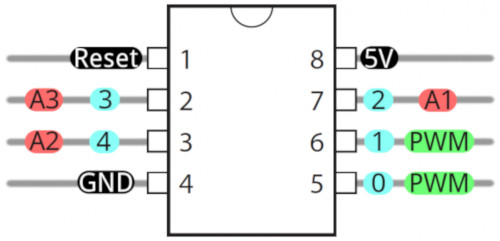
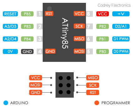
Attiny 45/85 Pinout and Description
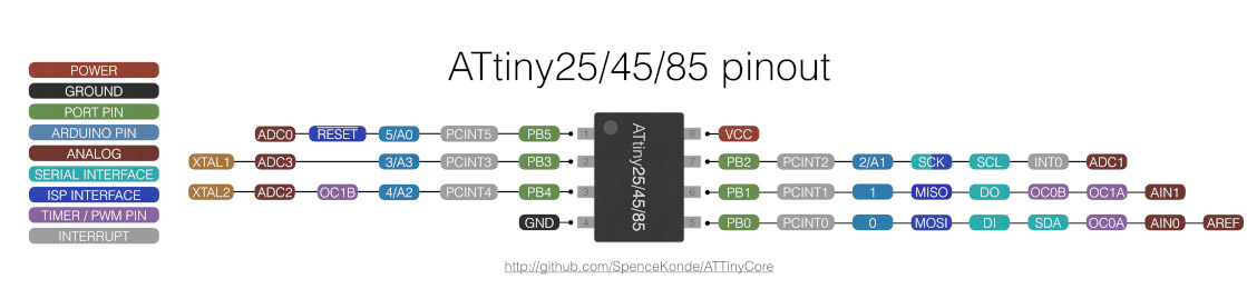
This module comes with only one port called Port B that is a bi-directional port and contains 6 I/O pins with internal pull-up resistors. The output buffers on PORTB are designed with symmetrical drive characteristics that come with both high sink and source capability. It is important to note that, Port B pins are externally pulled low and tri-stated that will source current if the pull-up resistors are activated. External and internal interrupts are available on the board, while 32 general purpose registers are included in the device that are mainly called data holding spaces. Two 8-bit timers are added in the device where one timer comes with compare modes and can be used both ways i.e. timer as well as a counter while other is high-speed timer/counter.
Attiny 45/85 Block Diagram
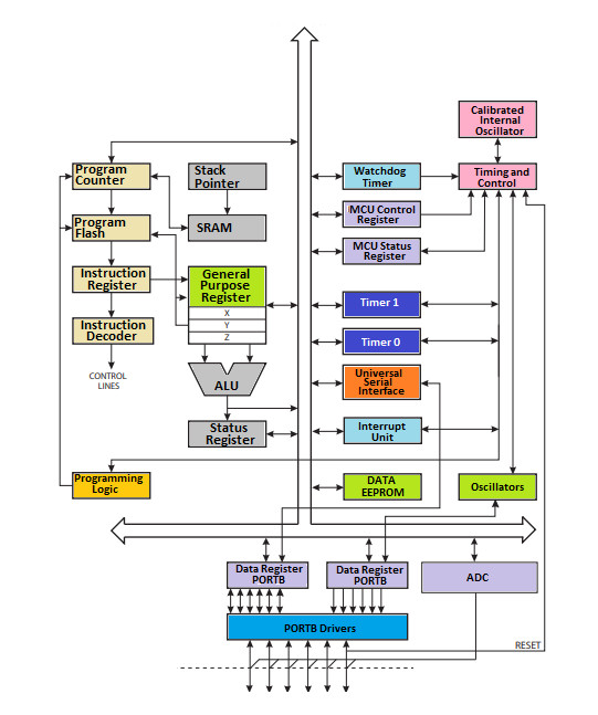
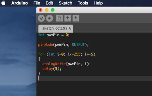
Attiny 45/85 basic PWM
The ATtiny85 microcontroller allows us to generate an analog output using PWM. The ATtiny85 microcontroller has two timers that can be used to generate PWM signals. The first is Timer 0, an 8-bit timer capable of phase-correct and fast PWM used for functions such as delay() and millis(). The second is Timer 1, another 8-bit timer capable of two fast PWMs with complementary outputs. Looking on, the ATtiny85 clock uses its internal oscillator running at 8 MHz, pre-scaled to 1 MHz by default (it’s okay to use an external clock, though). Also note that the ATtiny85 microcontroller provides two timers/counters, each providing two PWM comparators (OCR0A, OCR0B, OCR1A, and OCR1B), so in theory, we should be able to get up to four PWM outputs.
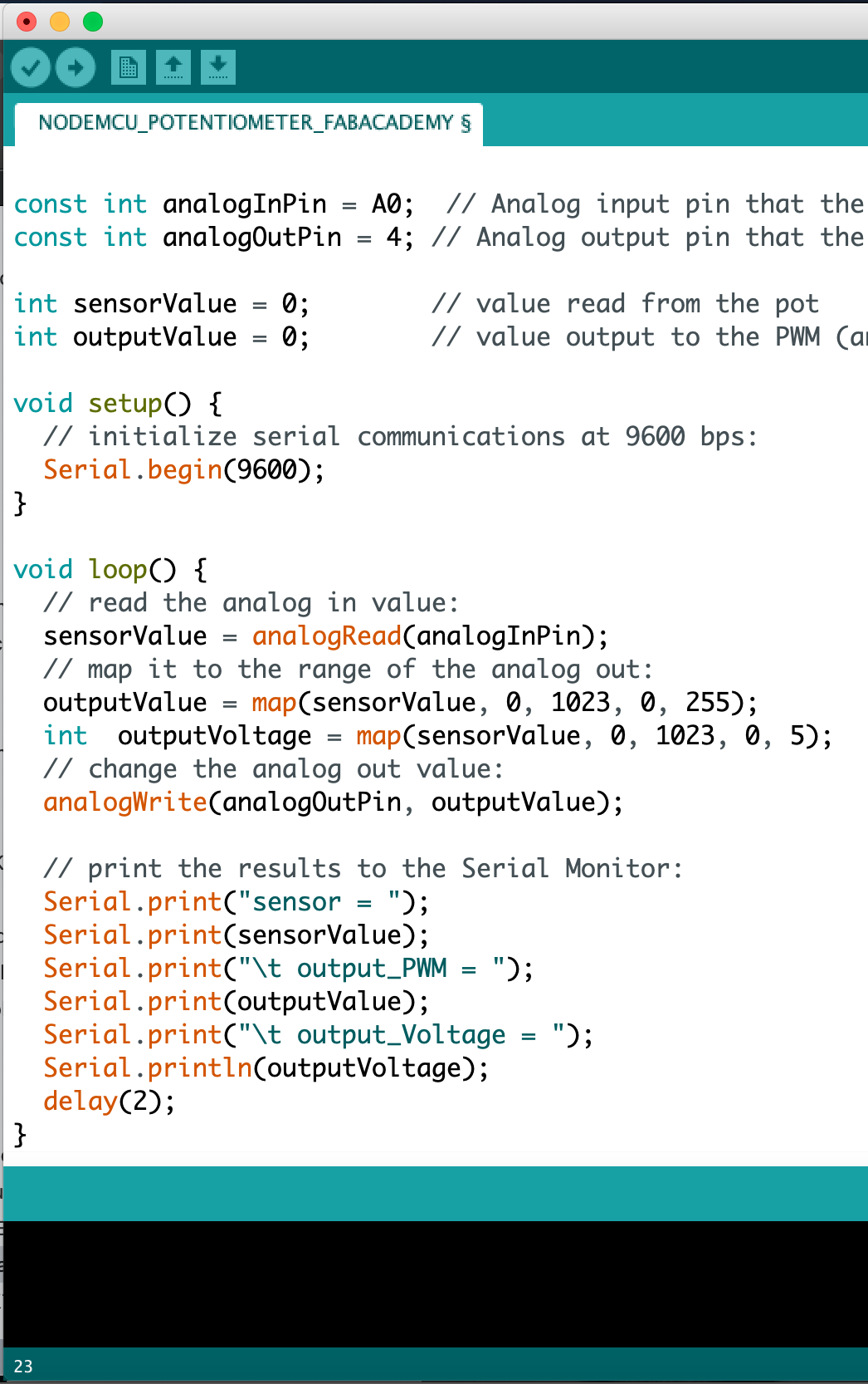
Analog Input and Output
Each of the I/O pins on the ATtiny85 are capable of digital input and output. Beyond that, some pins have special functionality.
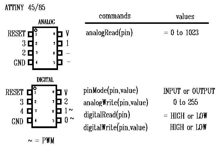
According to the datasheet, there are two analog outputs (PB0 and PB1) and three analog inputs (PB3,PB4 and PB5). Use them just as you would with any Arduino board. Use analogWrite([pin], [0-255]) to do PWM output. This functionality is available on pins 0 and 1. <
And use analogRead([pin]) to read an analog voltage between 0 and 5V, and turn it into a 10-bit representation of that voltage. Pins 2, 3, and 4 are capable of analog input, but, when using them as such, they should be referenced as A1, A3, or A2 respectively.
No Serial (UART). Yes SPI and I2C.
You may notice, on the listing of special pin functions there are no UART RX's or TX's. That's because the ATtiny85 doesn't have a built in hardware UART. If you try to compile any Arduino code with Serial.begin(9600)'s or Serial.print()'s you'll get an error.You can't print to the Serial Monitor. But the ATtiny85 does still have I2C and SPI, which are much more commonly used for sensor communication these days.
Interfacing ATtiny85 with Arduino
You can connect ATtiny85 with the Arduino following way.
- Arduino Pin 10 …………………. ATtiny85 Pin 1
- Arduino Pin 11 …………………. ATtiny85 Pin 5
- Arduino Pin 12 …………………. ATtiny85 Pin 6
- Arduino Pin 13 …………………. ATtiny85 Pin 7
- Arduino +5V…………………. ATtiny85 Pin 8
- Arduino Ground …………………. ATtiny85 Pin 4
Programming Languages
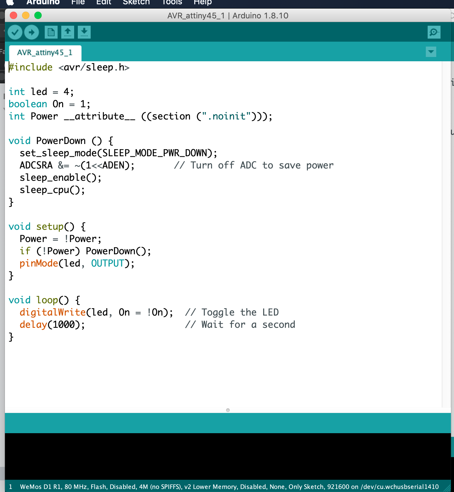
You can program the ATtiny in C This is very comfortable and amazing that a compiler manages to squeeze the code into the tiny chip.In order to use the chip as efficiently as possible, you have to understand how exactly the system works.
The CPU only understands numbers. Each number represents a specific function and sometimes triggers quite complex electronic processes in the CPU. Thanks to the instruction register, the CPU gets the numbers bit by bit from the program memory. A program for the ATtiny consists only of a long series of 2-byte blocks. A 2-byte block is called Word. The following program has a size of just 86 bytes and flashes one LED at pin 2. There are quite a few functions of the ATtiny to use: It initializes the timer and whenever the timer overflows, it turns on or off the port PB3, in addition, it puts the CPU in standby while it waits for the timer. At the end of the timer cycle, it fires an interrupt to wake up the CPU and turn on PB3:
- C using Arduino IDE libraries.Takes most space in the MC because it loads many libraries of Arduino into the chip. Easiest to use
- C using avr-gcc libraries. Takes very less space as compared to arduino c libraries as it loads only the essential c libraries from avr-gcc. Easier than assembly, it has a medium trade of between control and ease of use.
- Assembly language. Lowest level language, that give maximum control. You are literally wiring the logic manually inside the chip. Takes least amount of space as there are no external libraries to load. You need to know the internal working of the chip if you want to use it to maximum extent possible and it is used in cases where you want to use the chip to its maximum potential.
Things learned from Datasheets
For gaining knowledge about the pinouts of a microcontroller the datasheet is necessary, i.e. which pins are analog and which one are digital. Because for certain components e.g. a switch a digital output is suitable as it is either on or off. If you need an analog output for e.g. a potentiometer. Another aspect mentioned in the datasheet are the clocks of a microcontroller. They have an internal clock but if you want to make sure e.g. that when you communicate between two microcontrollers both have the same clock you can add an external one. The datasheet also shows you how to integrate this external clock into the circuit. Furthermore, a datasheet gives you information about the registers that are used when programming in plain C. I am using plain later in this assignment.
For my final project I need more pins than the Attiny 44 or 45 provides. For that reason I also started to read other microcontroller datasheets. For example I had a look at the ESP12. This ESP-12E is a miniature Wi-Fi module present in the market and is used for establishing a wireless network connection for microcontroller or processor. The core of ESP-12E is ESP8266EX, which is a high integration wireless SoC (System on Chip). It features ability to embed Wi-Fi capabilities to systems or to function as a standalone application. It is a low cost solution for developing IoT applications.
PROGRAMMING OF MICROCONTROlLER
After reading the datasheet there are new information I gained, which I will use to program the chip. There are may ways to program this chip, I will start with Arduino which is easy and popular.
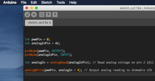
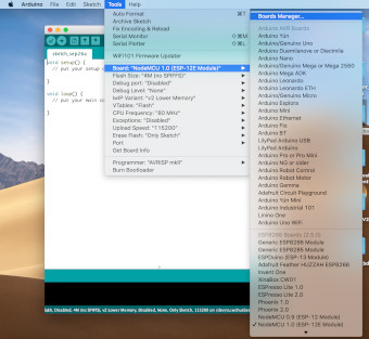
Arduino
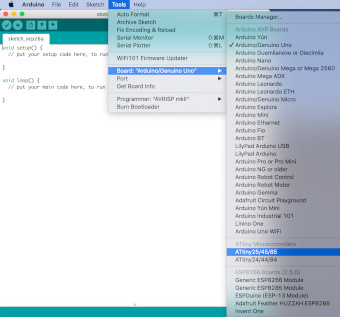
I started configuring arduino IDE to be able to program this chip. I searched for Third party boards for arduino IDE, and followed the first search result provided and looked for a way to add a board which supports ATtiny45.
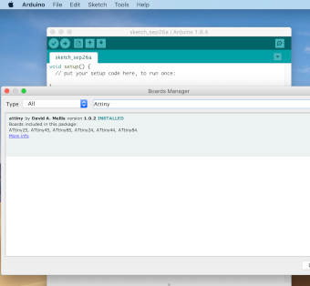
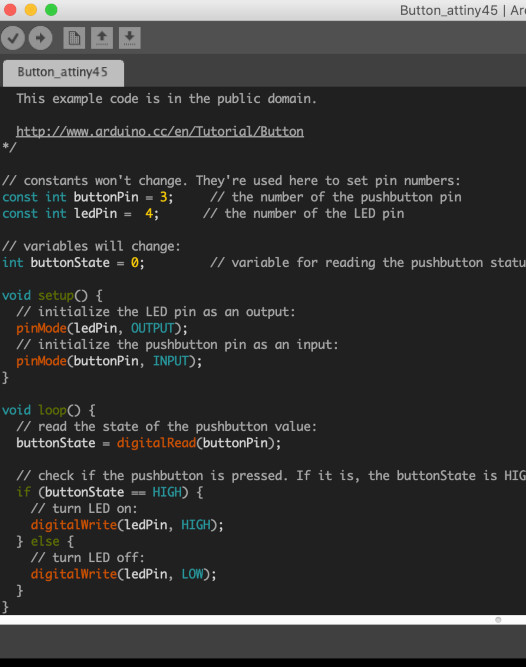
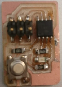
After Installing I was ready to start programming the board. In arduino I used its API to program the chip. The intent of this program is for turning ON the LED when the push button is pressed. PCB board is indicated below.
AVR libc
I have also programed the chip using AVR libc only and VIM as text editor. when programming with AVR libc there is a big difference with arduino, because now you are able to manupulate registers directly. AVR libc occupies small space on the chip compared to arduino API.
This tutorial help me to understand how to program an AVR chip in Linux more details.
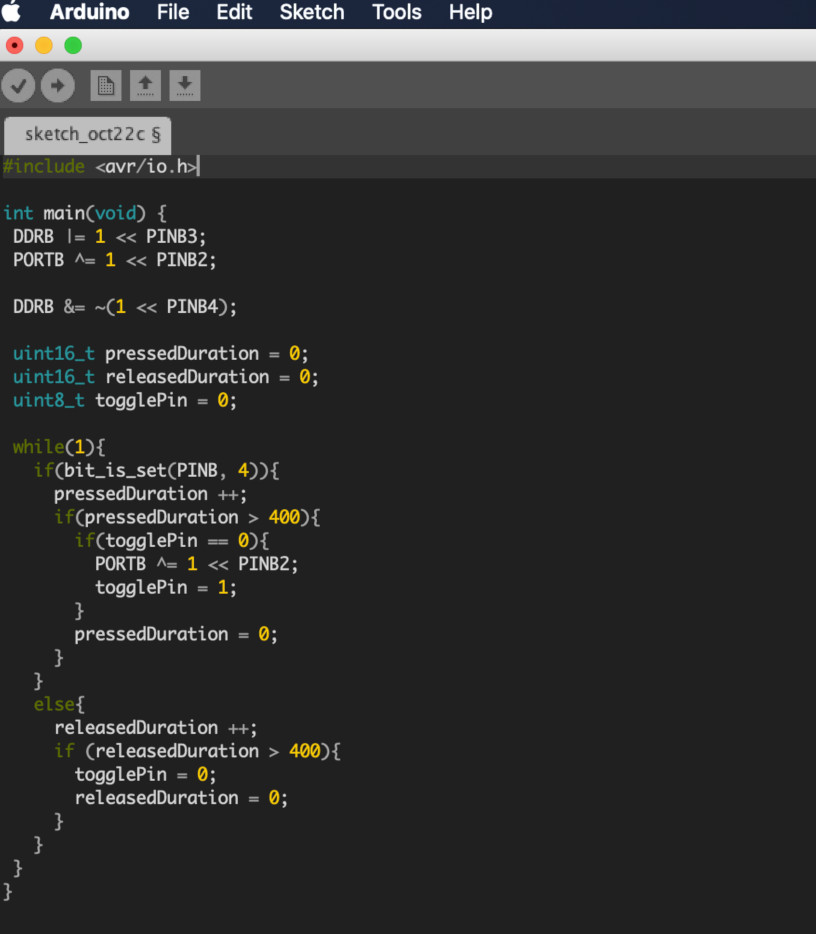
This program is for toggling the LED when the push button is pressed.
programming the board with FabTinyISP board
Used files