To accomplish my assignment, I referred to Brian’s FabTinyISP board available. The main objective of this assignment is to produce a FabISP board, which is an in-system programmer for AVR microcontrollers, designed for production within a FabLab. It allows you to program the microcontrollers on other boards you make. Here
These are three main parts:
- Milling the PCB
- Soldering components
- Programming the board
For time saving and simplicity, I decided to use Brian's ISP files (traces and outlines) available from Here
Afterwards, I generated the milling files from .PNG pictures. Here are the steps of creating Milling files with the Fab Modules.
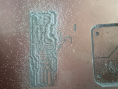
Traces
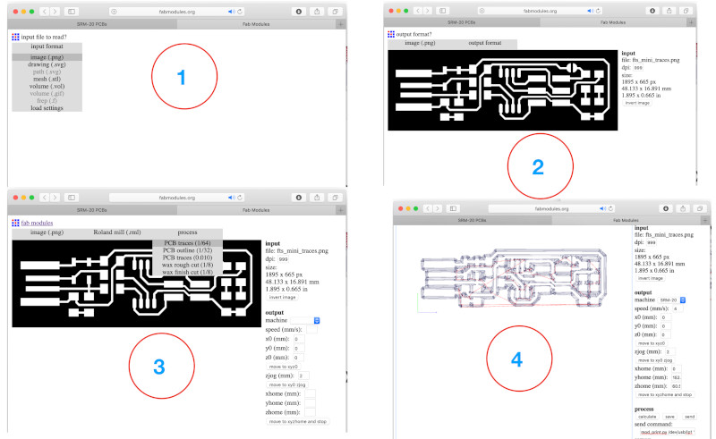
Outlines
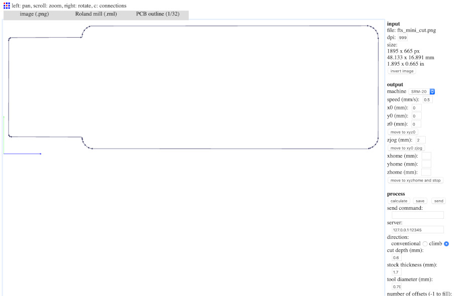
To print PCB I used Roland SRM-20 Desktop Milling Machine
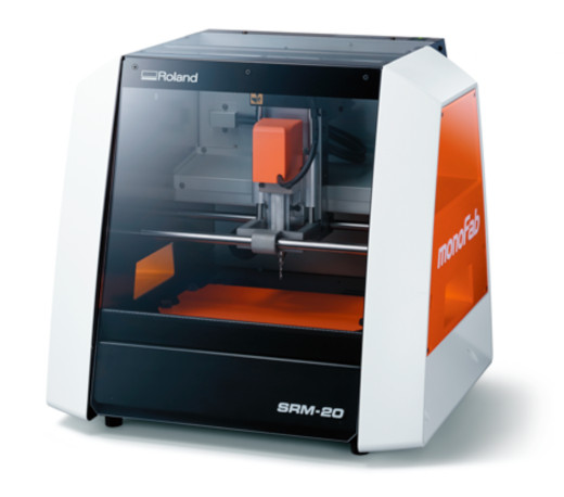
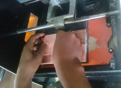
It is necessary to zero the x/y and z axis on your copper plate before running the cutting spindle. For the x/y, it is simply a matter of position the spindle by eye and selecting the set origin X/Y button: consider that the point selected is the bottom-left in your file.
To control this machine, I used its software called ”V-Panel”, it is the dedicated software for controlling this machine. Operation of this machine and various setup are performed using this software.
V-panel

The V-panel allows us to position the bit to the edge of the PCB Board, it will also help us to save the PCB board and others can still use the PCB sheet for their designs. Detailed instructions and recommendations of the milling process can be found here.
Cutting Tool Types
The SRM-2 0 supports the use of cutting tools with a shank diameter of up to 6 mm. I used the 1/64th inch bit for tracing the PCB lines and 1/32th inch for bit.
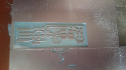
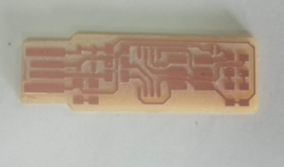
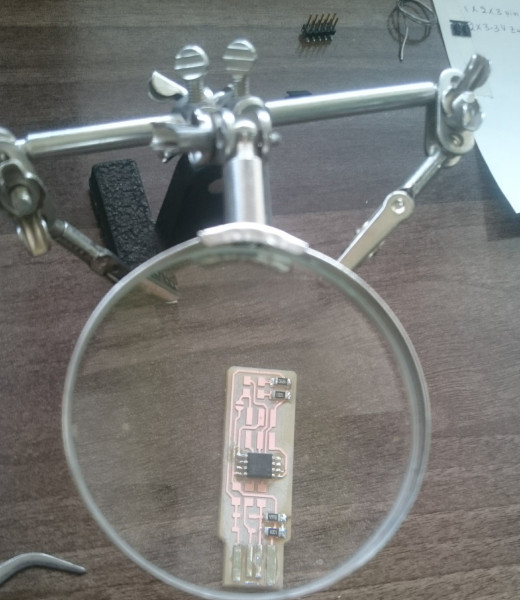
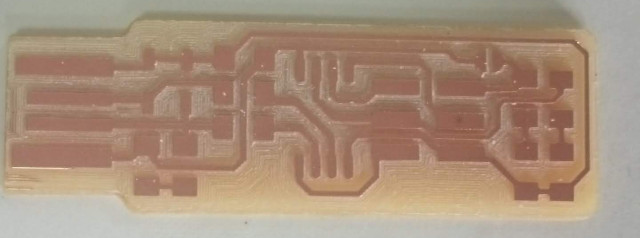
And this is the final result after cleaning the board
Electronics production
Activities:
- Making PCB for FABISP board
- Programing FABISP
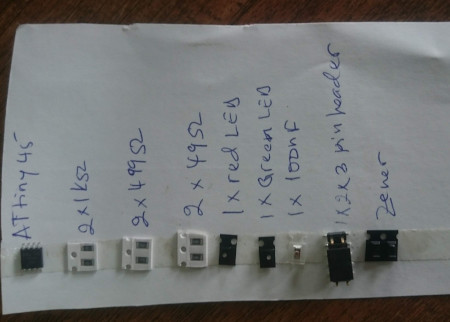
Used electronics components:
- ATtiny 45
- Resistors (2 of 1K, 2 of 499ohms, 2 of 49ohms)
- LEDs(1 of red, 1 of green)
- Capacitor (1 of 100nf)
- 1X2X3 pin header
- Zener Diode
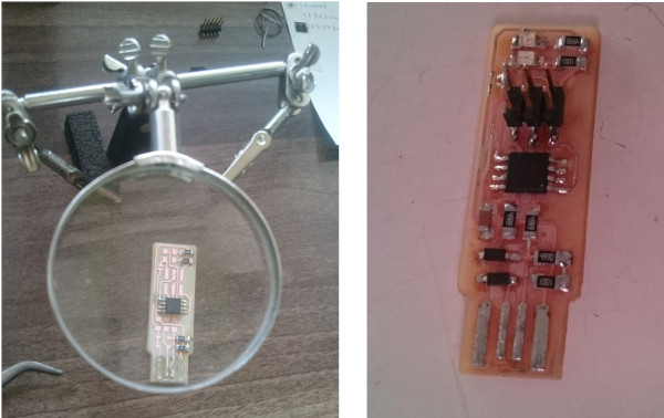
The next step is to solder the electronic devices on the printed board. After completing the soldering the is ready for programming.
Testing
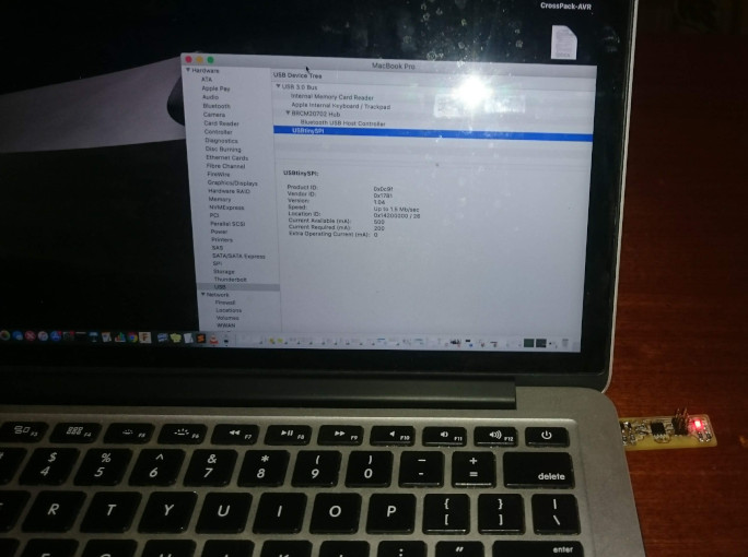
After mounting all the components I plugged it into the USB port of my laptpop, the device was detected as USBTiny SPI and Both the Red and Green LED’s lit up.
Programming
.After succesful soldering the board, the next step is to program the chip and this was the most challenging part of this assignment.
After downloading all necessary libraries and drivers, I connected another USB ISP board available in my lab to program my own FABISP board. I downloaded the firmware for ATtiny 45 from Here
Afterwards I checked if my FabISP was now recognised as a USB device by my computer. For safety reasons I used an USB hub, where I connected my FabISP. I checked under 'Apple symbol > About This Mac > System Report > Hardware > USB' if the device is shown.
After that I run the following commands.
- * make
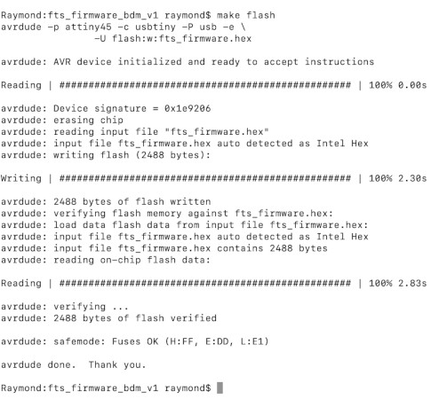
- * make flash
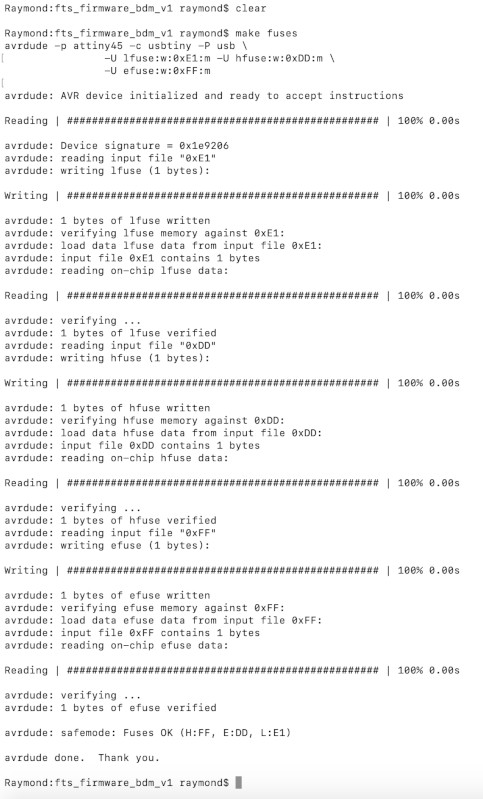
- * make fuses
Here you can see what happened after * make flash.
Challenge
It was not easy at the first trial, because after running "make fuse " command I accountered the following errors:
It was hard for me to identify the root of this error and after discussing with my supervisor Mr. Lambert, I found that I used a wrong firmare, instead of downloading firmware for ATtiny 45, I used firmware for ATtiny 44. Afterward, I uploaded the right one and everything goes well.
make flash
make fuse