Assignment 4
Electronics Production
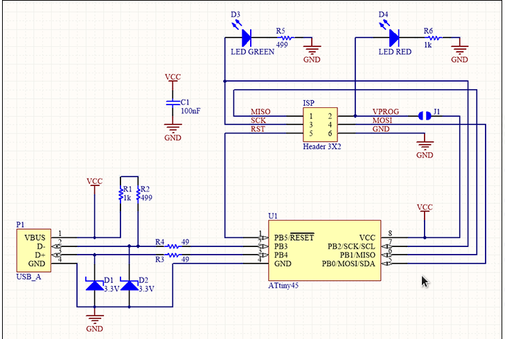
I have some theoritical information on electronics that I acquired in my 1st year of engineering. I don't know how they work altough I have an idea what some of the component do.I do find it very interesting as I have a lot of projects that could benefit from some moving parts.I wrote down the start and end points (in mm) and started milling. Because milling just .1mm of copper the dust is minimal and the dustbuster was not nescessary all the time. Though we wanted to see what the machine was doing. So I downloaded Brian's usb tiny circuit based on ATtiny44 as suggested by professor Neil I tried to understand how the circuit works with that attiny lower speed micro controllers Then I Transfered the png in fabmodules.org in order to get .rml documents:

Trace calculated in FabModules
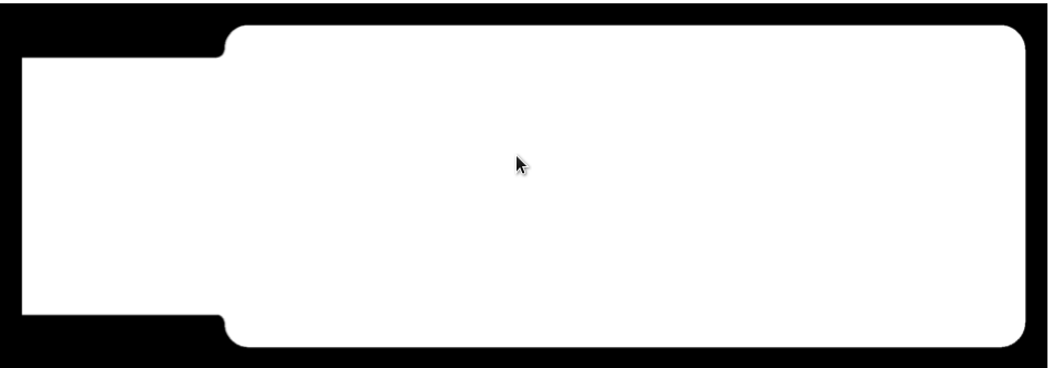
Outline calculated in FabModules
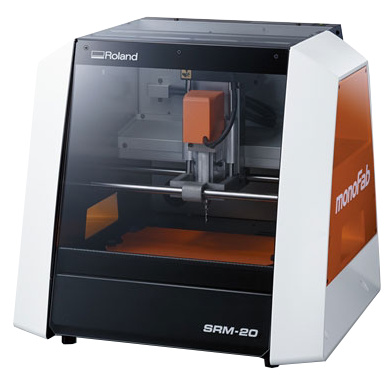
Roland milling machine SRM-20
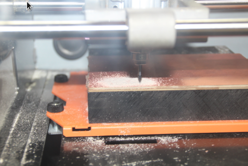
Tracing Tool already placed
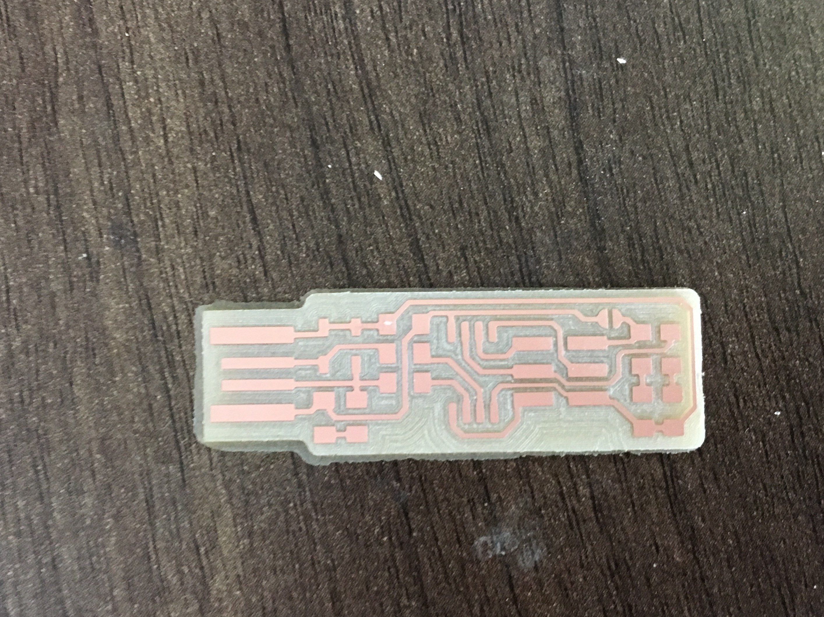
USB Done printing
Then I identified all the components stated in the document and identified where there were supposed to be soldered, then I soldered them as I have ad some practice before helping my team in soldering electronics components although the difference here is that the packages are SMD soldered on the Top surface
Componets used
1x ATtiny45 / 2x 1Kohm resistors / 2x 499Kohm resistors / 2x 49Ohm resistors / 2x 3.3v Zener diodes / 1x red LED / 1x green LED / 1x 100 nF capacitor / 1x 2x3 pin header / As mentioned above I have some knowledge in soldering although the packages I used to solder are not SMD, The SMD packages are tiny and are soldered on the surface.,So I based my self on the details that are in Brian's link
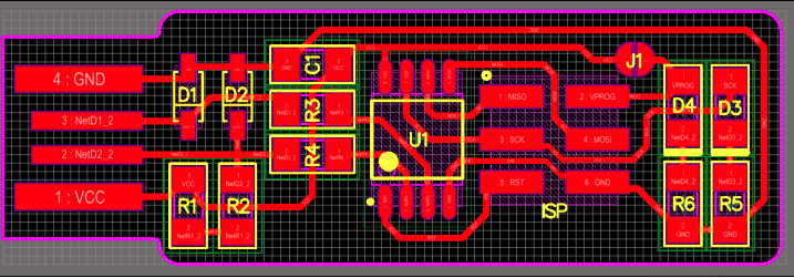
The details I based while soldering the components
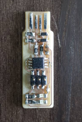
Soldered USB Tiny


also I have used Vinyl cutter machine to know how it realy work and I learnt is cut studio software. I have used google to download vector image after that you import in cutstudio the following images show you all process.


