Electronics Production: Printed Circuit Board Production
In electronics production this week we had to try and test the PCB milling machine in our lab as introduction to electronics and introduction to PCB production. For this assignment we were provided with the design of the circuit board, however, we were suppose to fabricated using a milling machine, then do an initial programming for the PCB to work.
Group Assignment
For the group assignment this week we are suppose to test the designs rules of electronics production. To do that we used the following PCB template and fabricated using Roland MDX-50 which is the machine we have in the lab.
The original image size is extremly big so we scale it down and fabricate it, however the final PCB turned out extremly small, and the designs rules cannot be validated with this size.
However, after we adjusted the size of the PCB image, the resulted PCB turned out good, and here is the final results.
The Milling Process
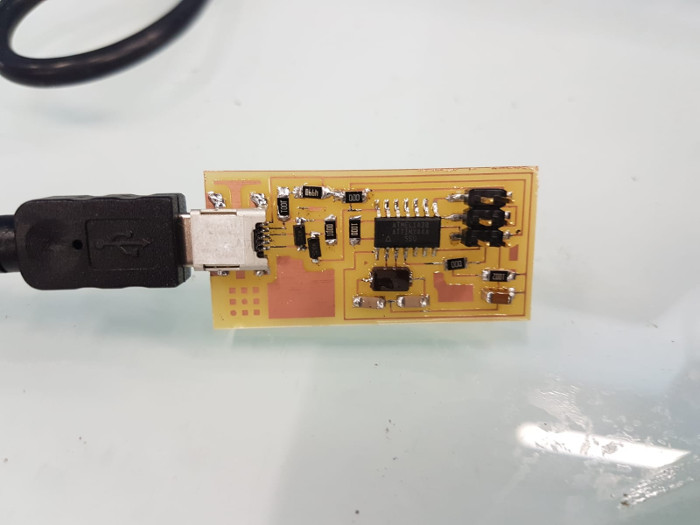
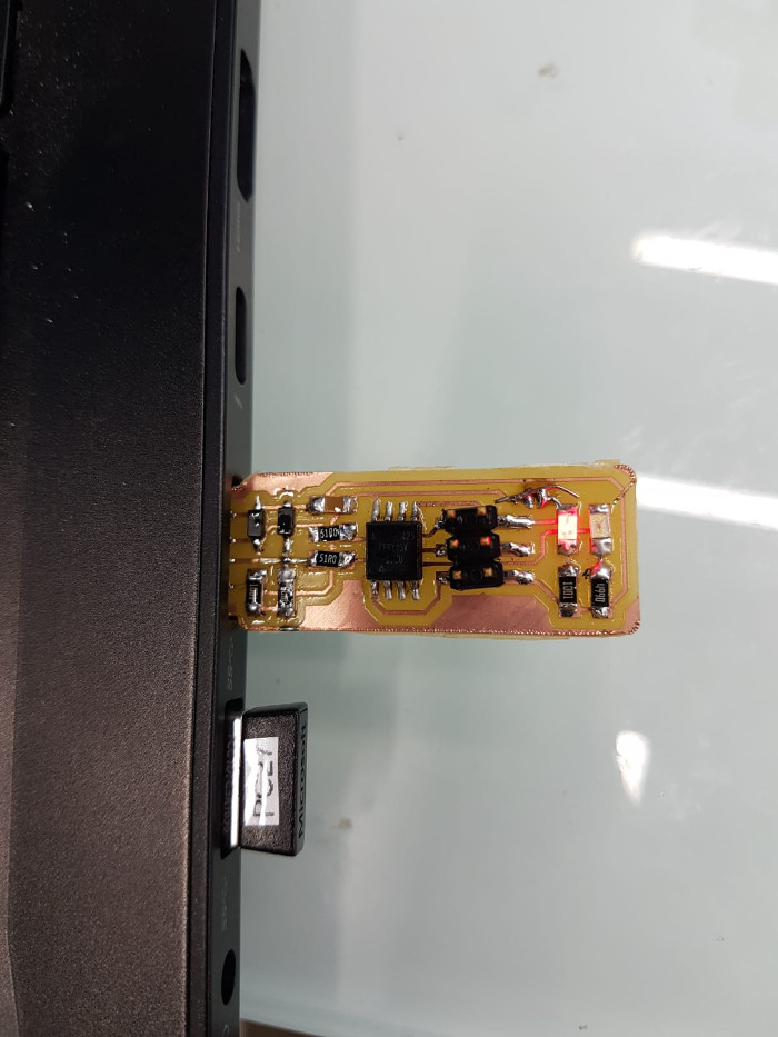
In this assignment we are supposed to try the process of milling a ready designed PCB, solder it, and then finally program it. There are two PCBs to mill, solder, and program. The first PCB is the FabTinyISP, and the second PCB is the FabISP, both PCBs traces and outlines images can be downloaded from Fab Academy tutorial website.
The milling machine we have in QBIC Fab Lab is the Roland MDX-50, which is one of the powerfull milling machine available in market. It is very realiable, accurate, and user friendy. It has a lot properties, but the main and the most handy property is that it has an tool change method, which is very handy when it comes to milling a PCB, because you need to use one tool for the traces, and other tool for the outline.

Moving on, the first thing to do after downloading the files of the PCBs is to go to Fab modules to prepare the files for the milling process. As I mentioned above there are two PCBs, meaning I will have to prepare four files in fab modules to use with the machine, two for the outlines, and two for the inner traces.
Therefore, there are two different process for preparing the files:
- 1. Traces Settings:
- * When first open the software, it asks to specify the type of the imported file, which is in this case is PNG.
- * Then the type of the file needed to be generated using fab modules, and for this it is going to be ".rnl" which is the formate that the machine takes.
- * Finally, the tool that is going to be used during the milling process. Ans since I am starting with milling the traces of the PCB, the tool to use is (1/64).
- * After adjusting the parameters required to prepare the imported file, now it is time to adjust the output settings, which will appear on the side screen of fab modules. Here we need to add the machine details in terms of machine name, speed (mm/s), origin coordinates and homing. The input data should be as shown below. taking consideration the following: The machine selection, MDX-50 is not available but MDX-40 is similar to it. The Zjog represents the Z level of the machine when it is traveling to a different location.
- * Also by selecting the process “PCB traces (1/64)”, automatically the process details will show on the right side. The tool diameter needs to be changed from 0.4mm to 0.09mm which approximately corresponds to the diameter of the V- tool shown in the picture. However, the V- tool is usually defined by angle (i.e. 45 degrees).
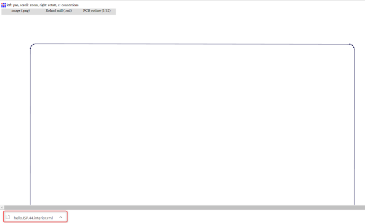
- * Finally click on “Calculate” to generate the RML file for the MDX-50. The circuit traces will be created with directed blue lines representing the machine milling path and red lines represent the jogs between different paths.


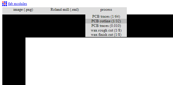
- 2. Outline Settings:
- * For outline setting the first two stages are somilar to traces settings, will have to upload the image of the circuits outline, and then we should choose the output file, which in our case is (.rnl)
- * However, when it comes to the type of tool, it should be (1/32) since now will be milling the outline, and not the traces.
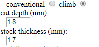
- * For the output settings, in the left side of fab modules screen, the machine details parameters are exactly the same as the traces values. However, now we should adjust the cutting depth parameter, in order for the machine to completely cut the copper pieces to completely create the PCB.
- Check the Stock thickness which is the thickness of the material e.g. 1.7mm. Cut depth is the depth the tool will cut in one pass. This can be done in one go when selecting the depth to be equal or slightly bigger than the material thickness (e.g. 1.8mm cut depth can give very good cut through). Tool diameter is kept as the default 0.79mm for 1/32” tool. Then, Click “Calculate”.
- * Finally click on “Calculate” to generate the RML file for the MDX-50. The circuit traces will be created with directed blue lines representing the machine milling path and red lines represent the jogs between different paths.
- *The above process is to prepare the files for the FabISP board. Similar process will be followed to prepare the FabTinyISP, for the traces and outline.
Moving on, After downloading the file, the machine should be settled up with the copper board mounted and the needed tools. First, prepare the copper plate sheet and make sure it is clean.
Then the machine need to be prepared to perform the milling process. The machine setups are the following; z-origin, x-origin, and y-origin.
To adjust the z-orging, the z-probe need to be ready and should be snapped over the special socket as shown. Also the detection pin need to be loaded to tool slot number 6.
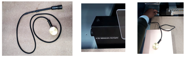
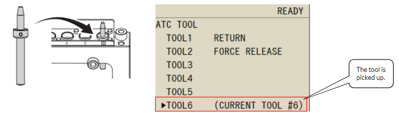
Then from the machine Keypads click on "Menu" button many times until you get “ATC TOOL MENU” for the automatic Tool Changer. Use the hand wheel to select the tool with where the bit is attached to the tool holder. E.g. here TOOL6 which is the detection pin is selected. The spindle will move to get the selected tool then it will show on the screen that the selected tool is tool #6.
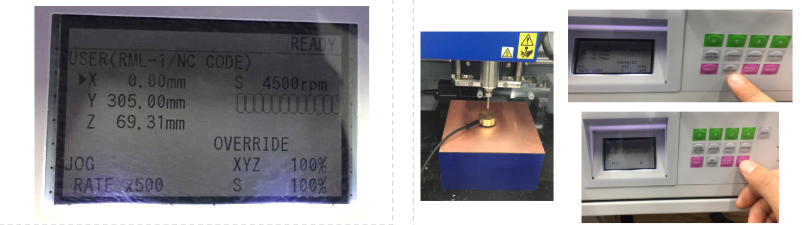
From the Menu button we click multiple times until to go to “USER (RML-1/NC CODE)” menu. This will help in adjusting the location of the machine spindel until the Z-prope, to adjust the z-orgin. For instance to change the x-coordinate, we should select it by hand wheel and then hit enter, after that with the hand wheel it moves to the positive or negative direction.
From the hand wheel move, the x and y to have the spindle directly facing the z-probe metallic piece. After that, click on Z0 SENSE from the panel. There will be a message displayed on the screen, to confirm Z0 SENSE click ENTER.
Before start with the milling process, the X and Y origin coordinate needs to be determined and the spindle speed needs to be asjusted. From the laptop and using VPanel softwar, select the gear icon. This will allow you to access the machine setting window. Select “Origin” tap and modify the XY positions to suit the position of the material. When you reach the desired point, select “XY” to be the origin position and click on “Set”.
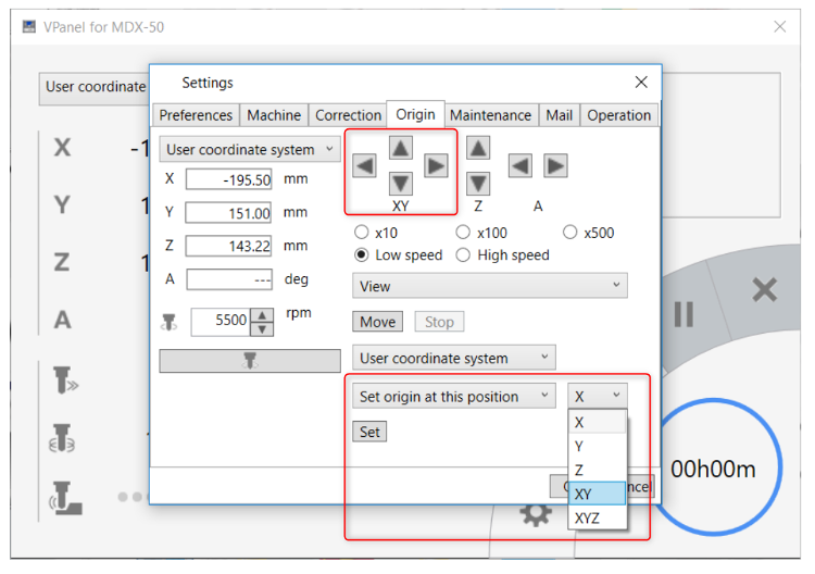
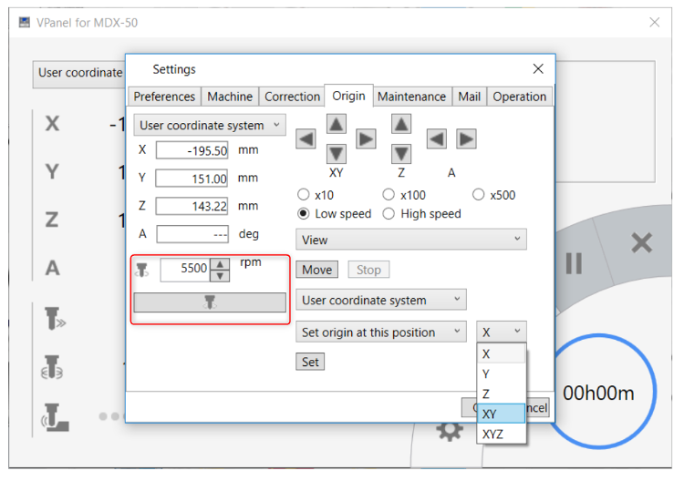
Then the speed of the spindle should be increased by increasing RPM from 4500 to 5500 rpm. Then from the spindle icon fix the new speed. Finally, click OK.
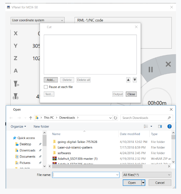
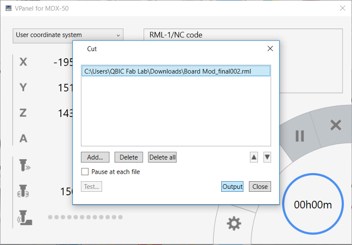
Finally from VPanel software, select “Cut” icon, to upload the (.rml) file for the PCB generated earlier.
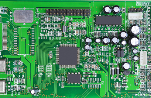
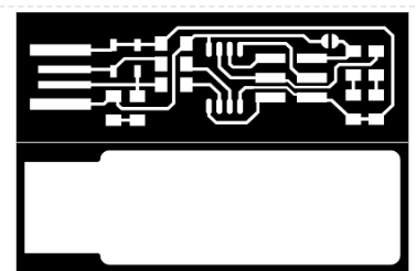
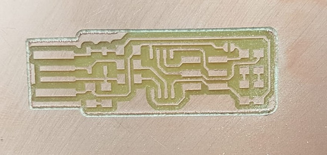
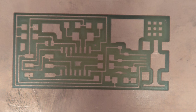
Here are the results of the milling process for FabTinyISP, and FabISP repectively. By following the exact process it was eas to mill the PCB without any issues.
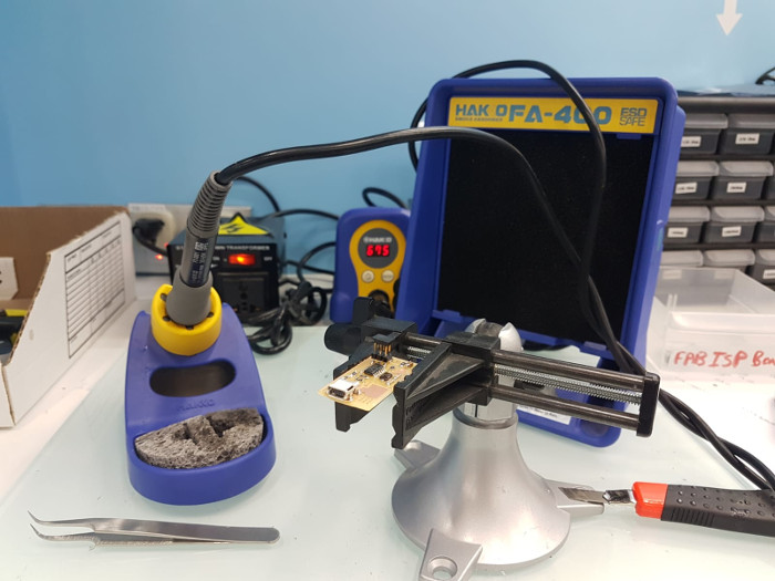
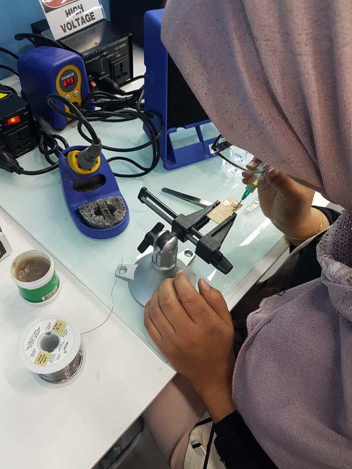
PCB Soldering Process
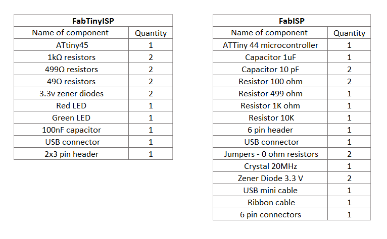
After completeing the PCB milling process. It is now time to solder the both PCBs. For this assignment the list of components was provided so the only thing left for us to do was to learn how to solder, using the two PCBs.
The components lists are the following for FabTinyISP, and FabISP respectively.
The soldering process went smooth and easy, my soldering iron tempreature was setted on 675 degree celsius, and since I was soldering SMDs, I used flux to me in securing the components on their places and to insure that the soldering wire would only stick to the copper board and not cause any miss in the PCBs.