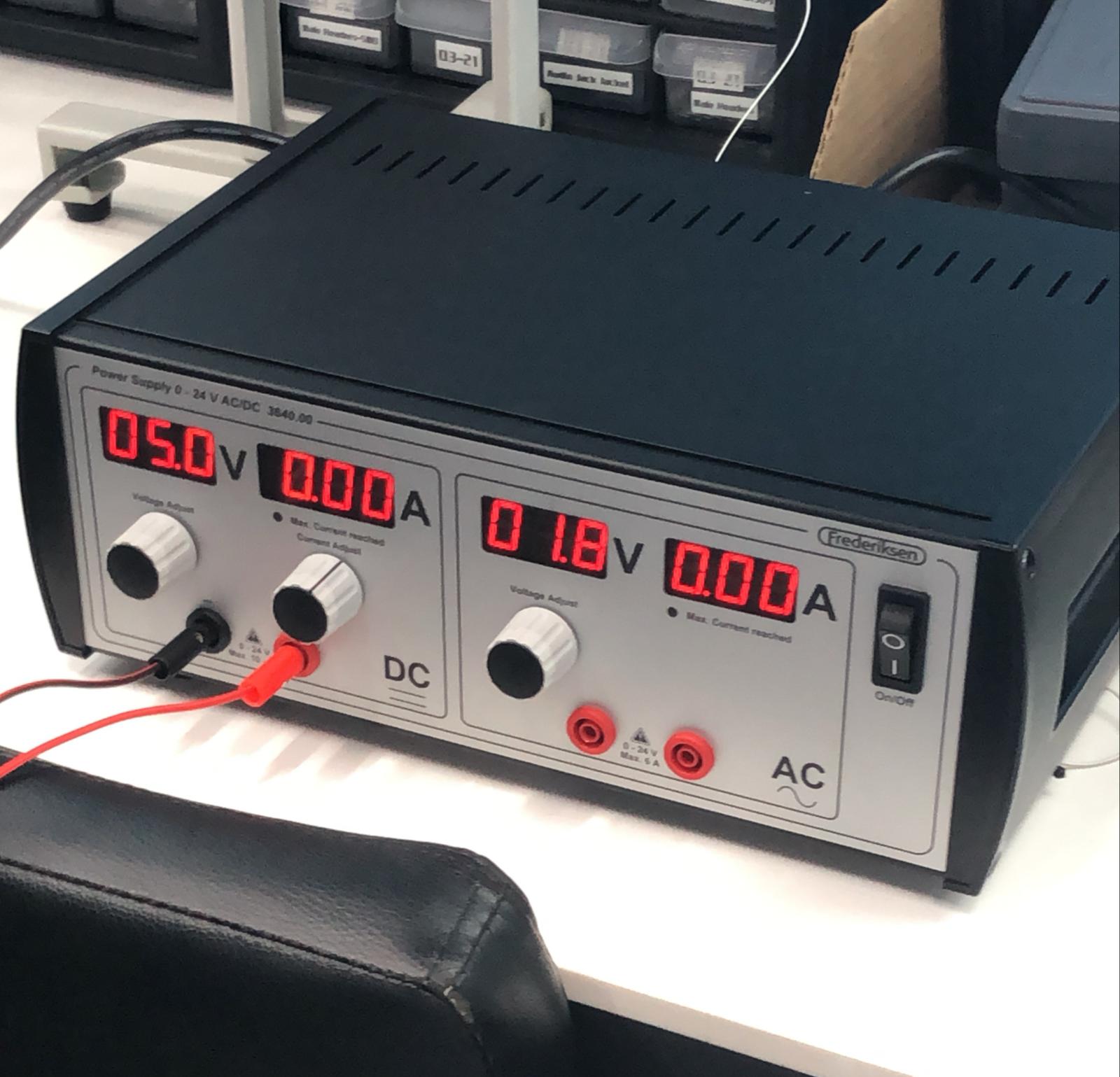
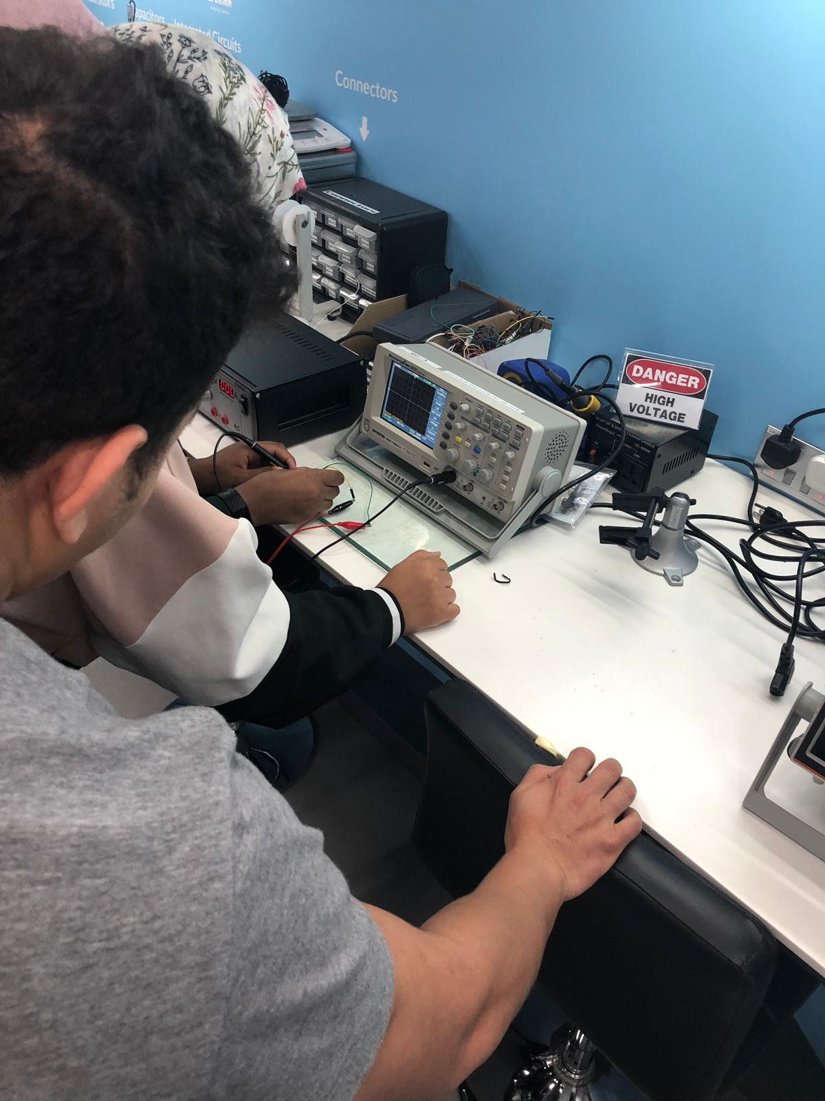
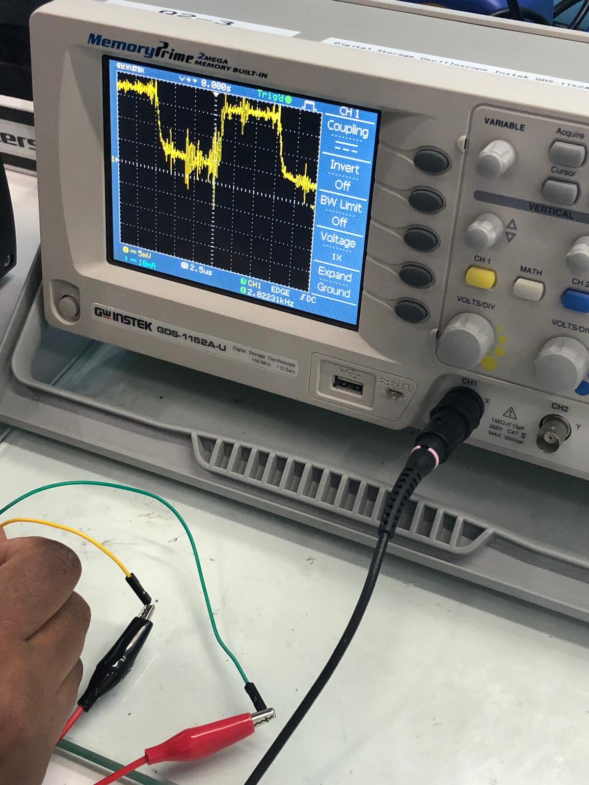
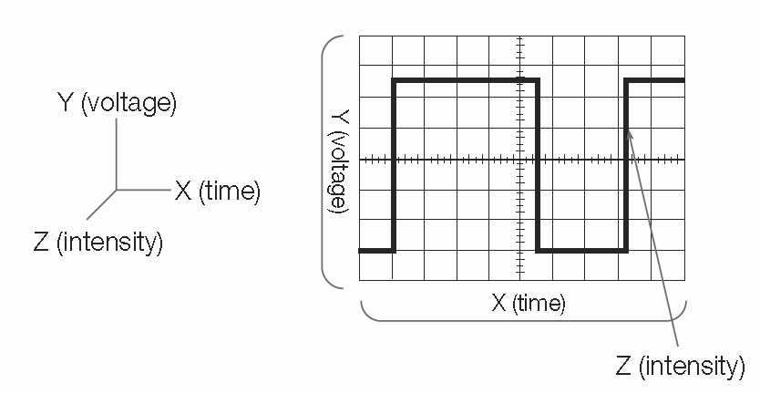
so the group assinemnt was to test to observe the microcontroller board. we decided to work with oscilloscope and voltage source. the oscilloscope is a laboratory instrument commonly used to display and analyze the waveform of electronic signals. In effect, the device draws a graph of the instantaneous signal voltage as a function of time. and the voltage source is a two-terminal device which can maintain a fixed voltage. An ideal voltage source can maintain the fixed voltage independent of the load resistance or the output current.
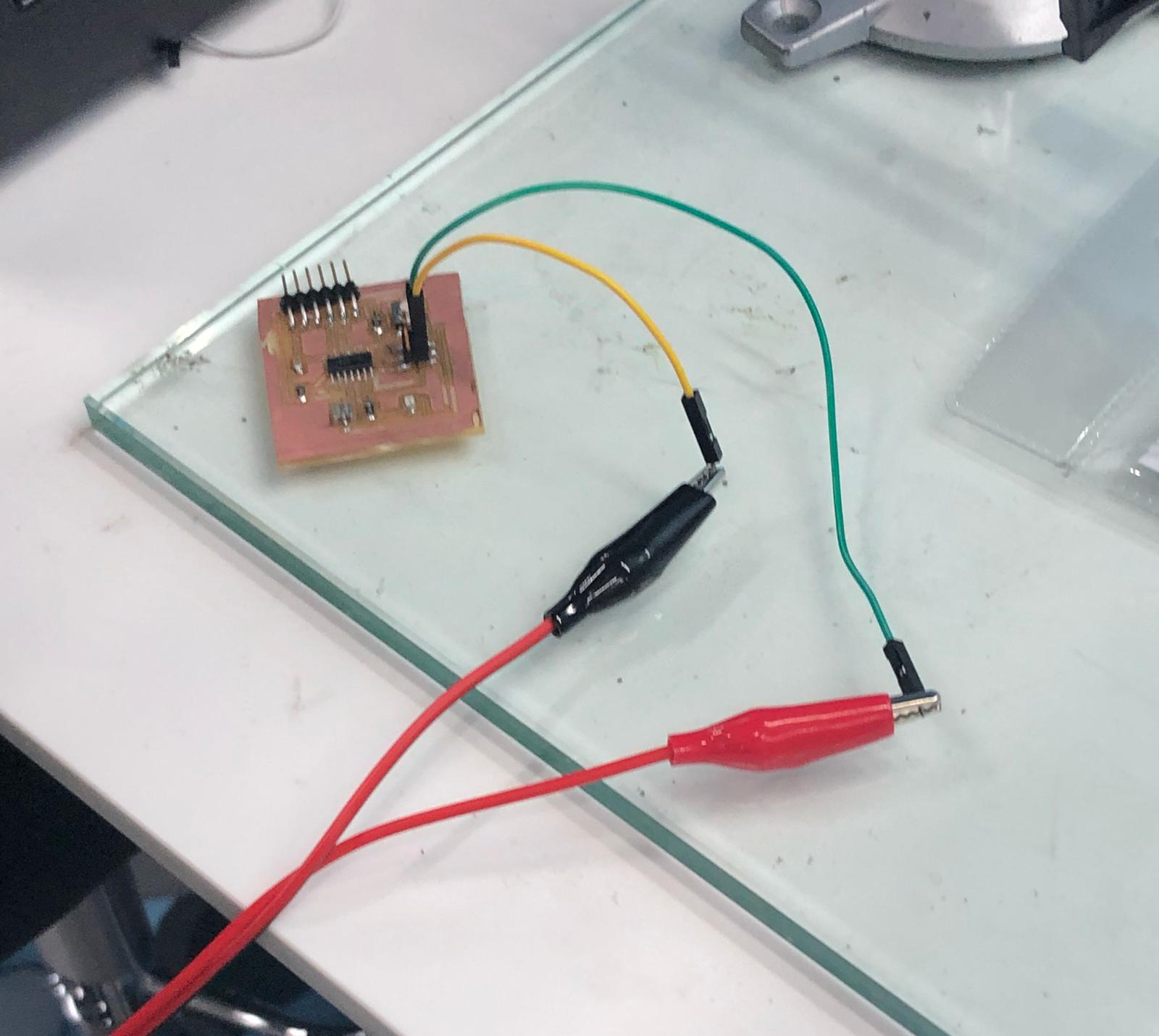
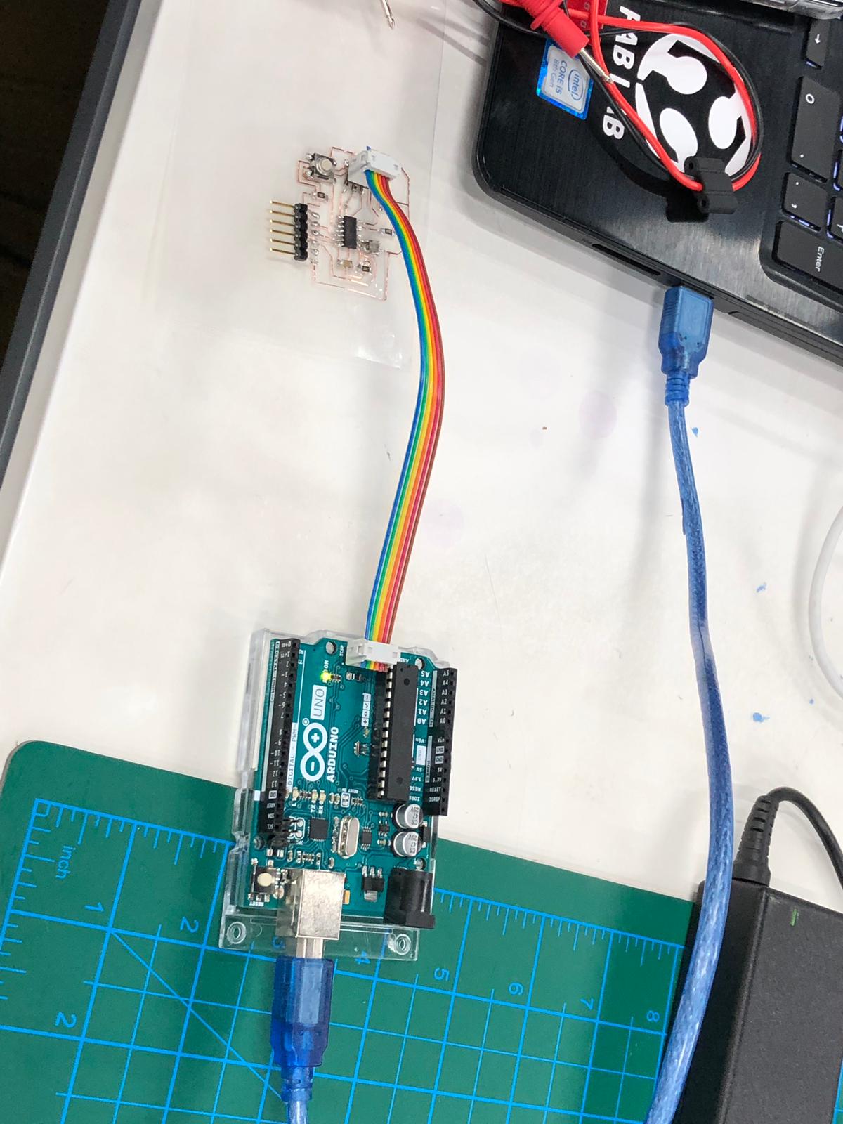
the oscilloscope will be used to observe the crystal oscillator and the voltage supply will be used to suplay power for the crystal oscillator. so we connected the voltage supply to the hello world board and connected the oscilloscoppe to both ends of the crystal oscillator and started the device to observe the signal.
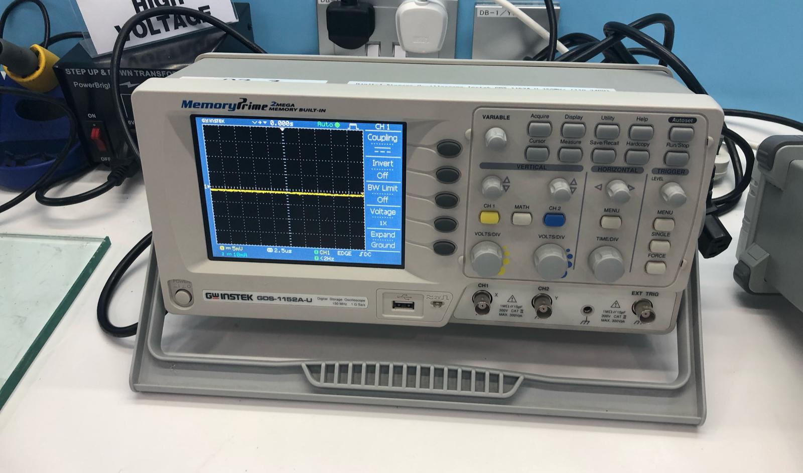
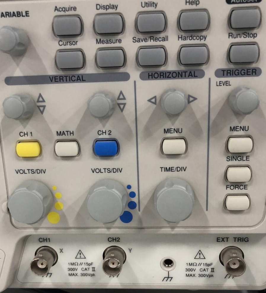
we had to adjust the settings by rotating the nobes on the device. we change the Volt/Div and Time/Div to make the signal clearer.
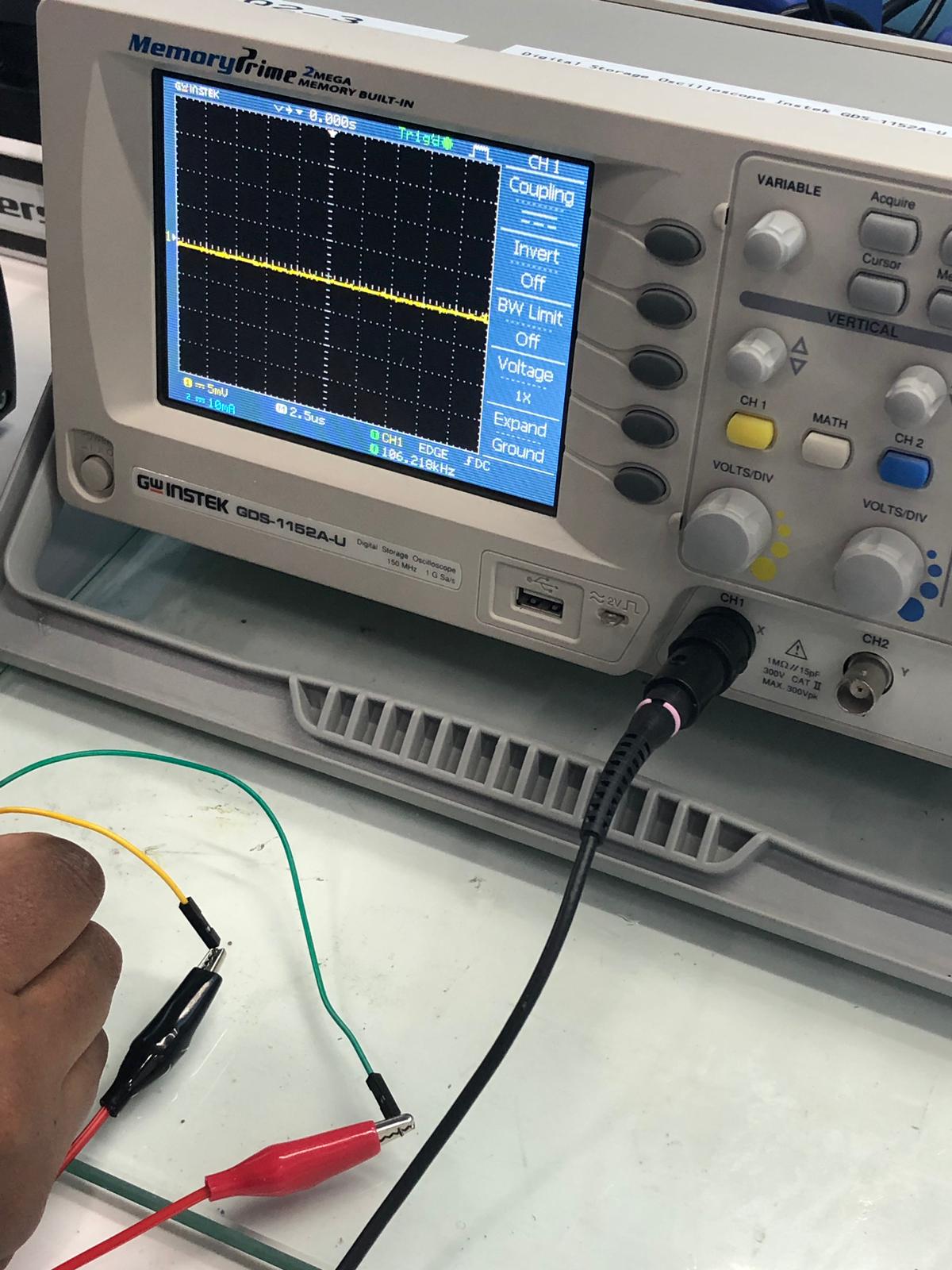
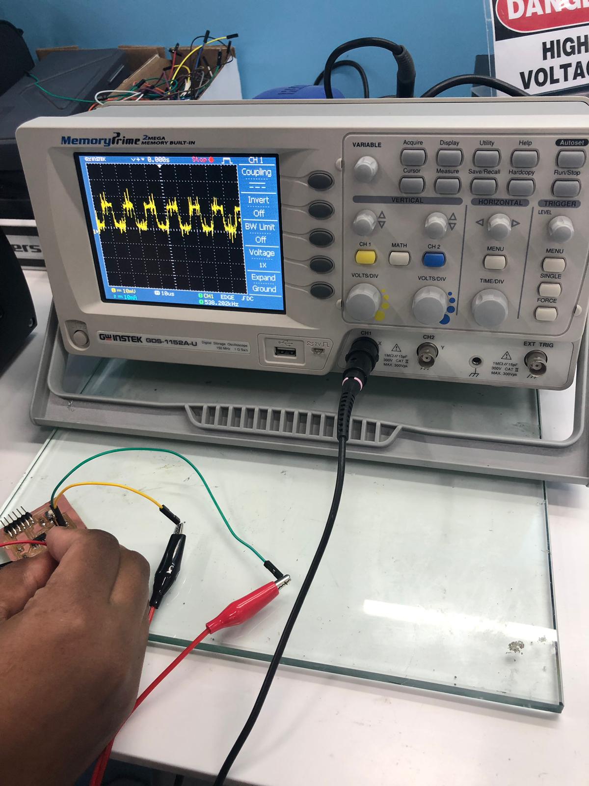
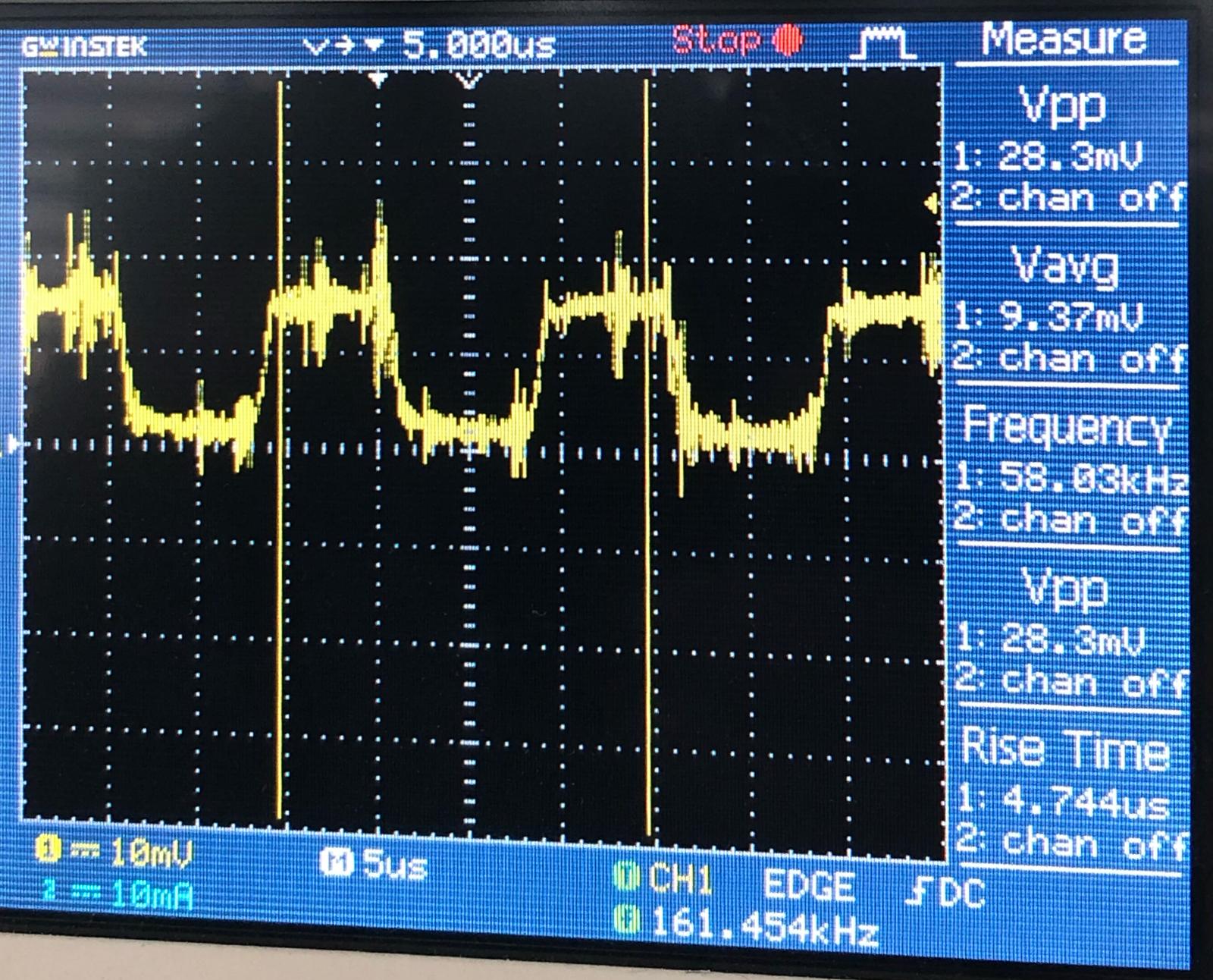
we were able to see the pulse signals comming form the oscillator so then we used the cursor to select one period and calculate its frequancy.
the device showed that the frequancy is around 60 KHz when in reality it is suppose to be 20 MHz we tried it on multiple boards but it was giving the same our instructor advised that this machine is not relaiable when it comes to calculating frequencies we should use one that have forier analysis.
Designing The PCB
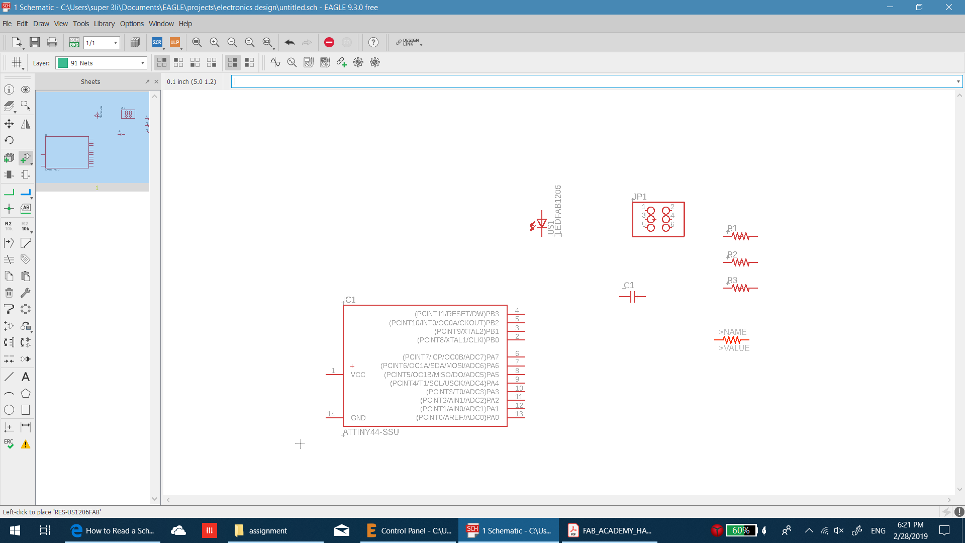
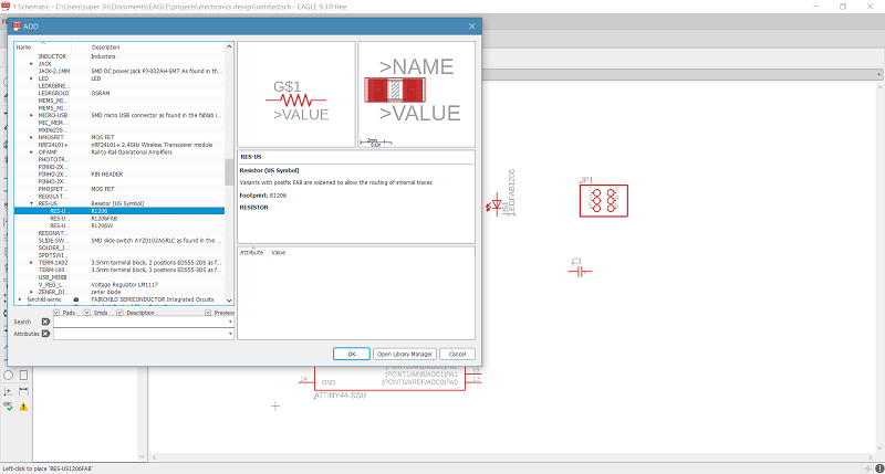
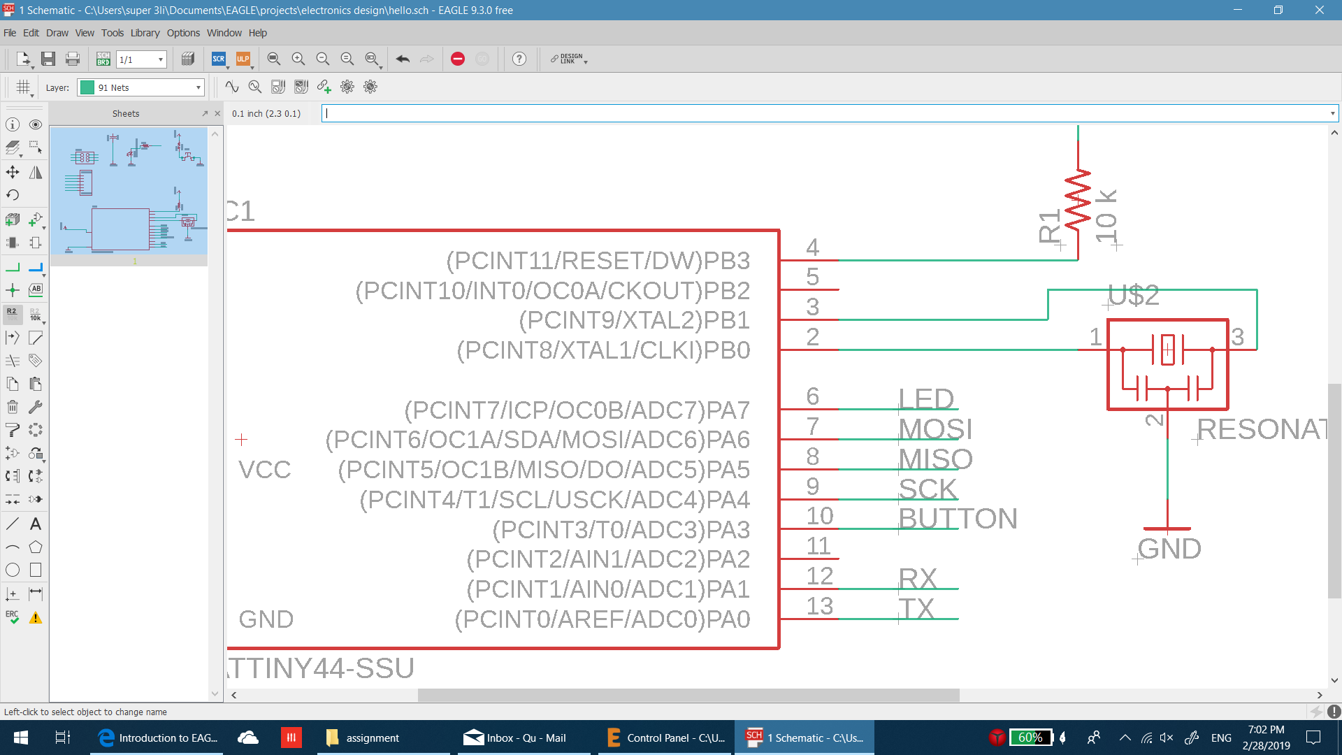
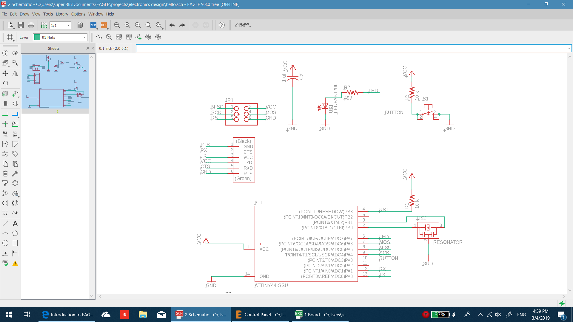
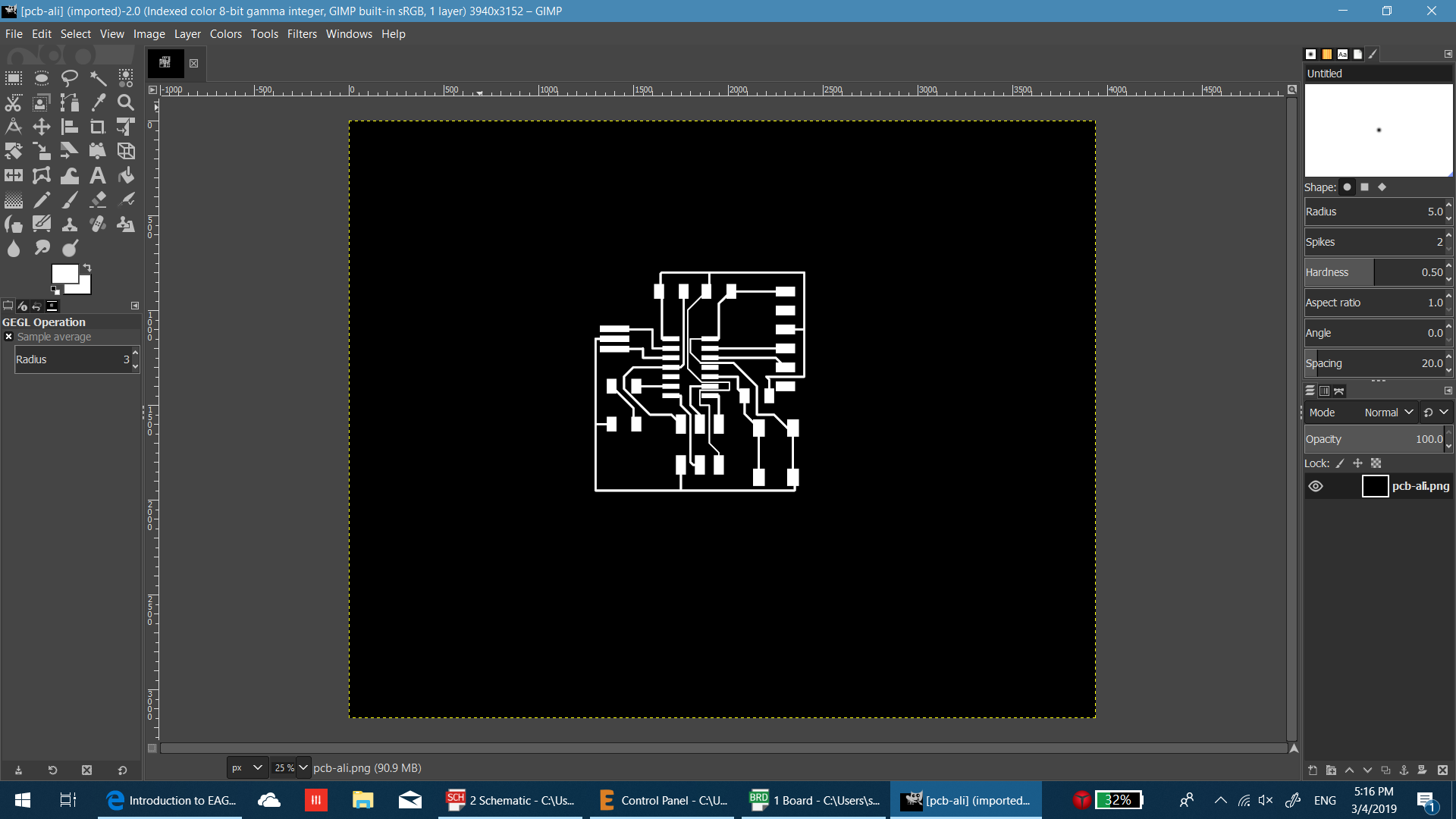
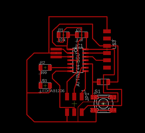
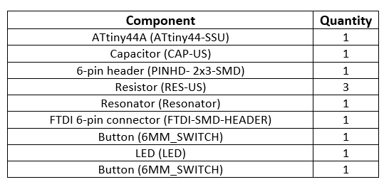
In this assignment i followed the tutorials to design a pcb. its again the first time for me to design an electric circuit. so first thing is to import all the required componants. for that a library must be installed first. its called fab. its bretty easy to do that you just have to manage laibrary and add the required files.
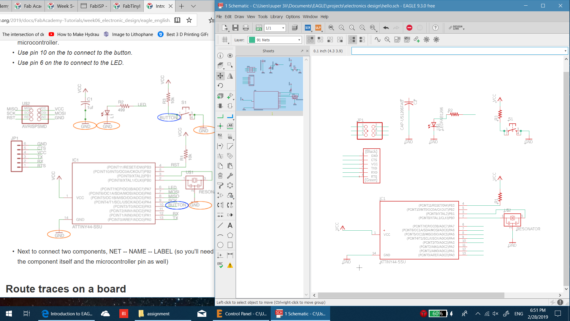
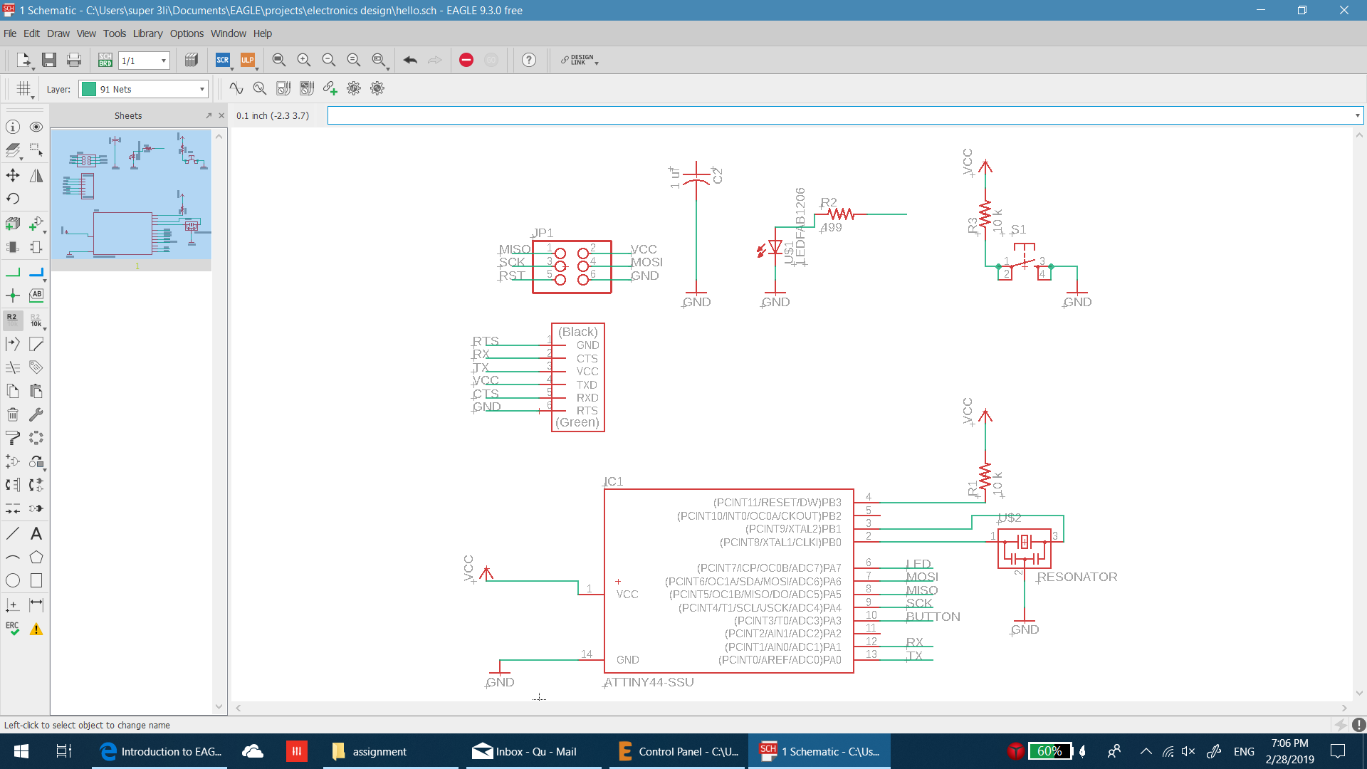
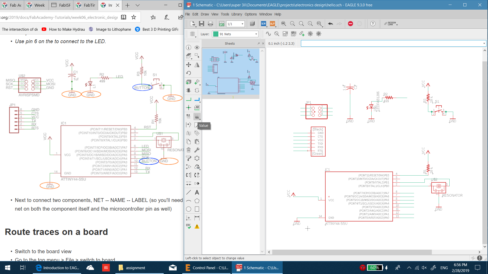
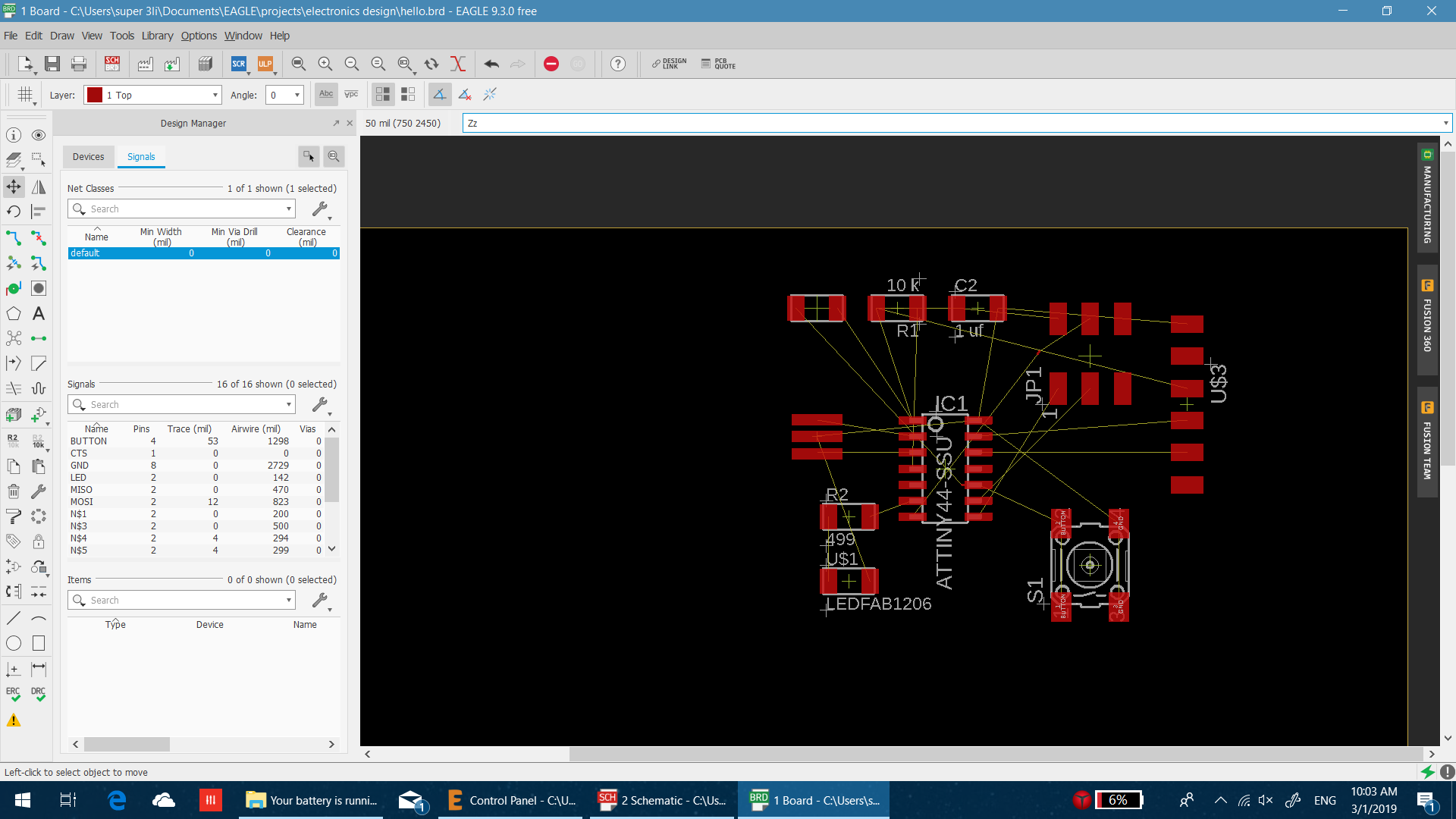
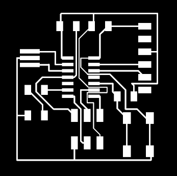
once i got all the required componants infront of me i started connecting each part to its counter part. i used labeling to assign names to some ports and the program can understands if to componants must be connected by these labelig. the other command i used is to assign the values and its just for my referance. once its ready i took the design scematic to board view and it gave me the design with all the componants. the good thing it showes lines that need to be connected.
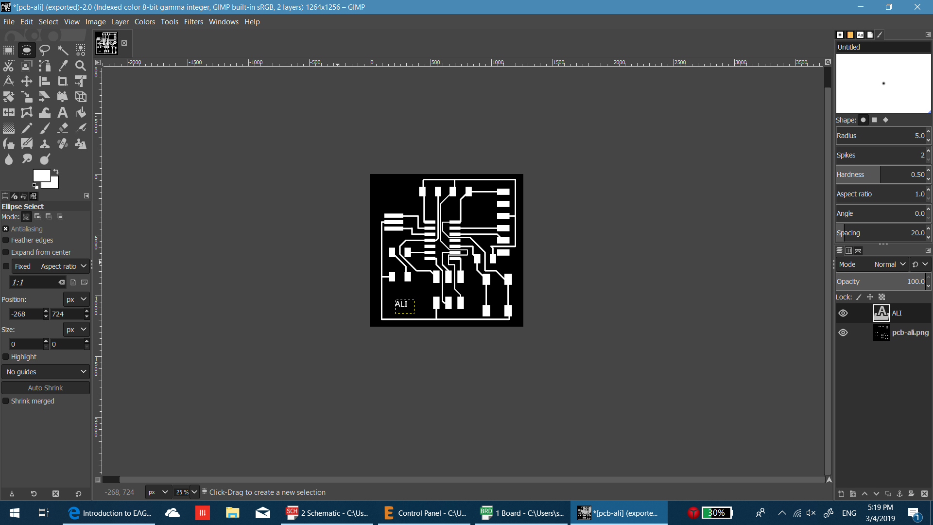
Making The PCB
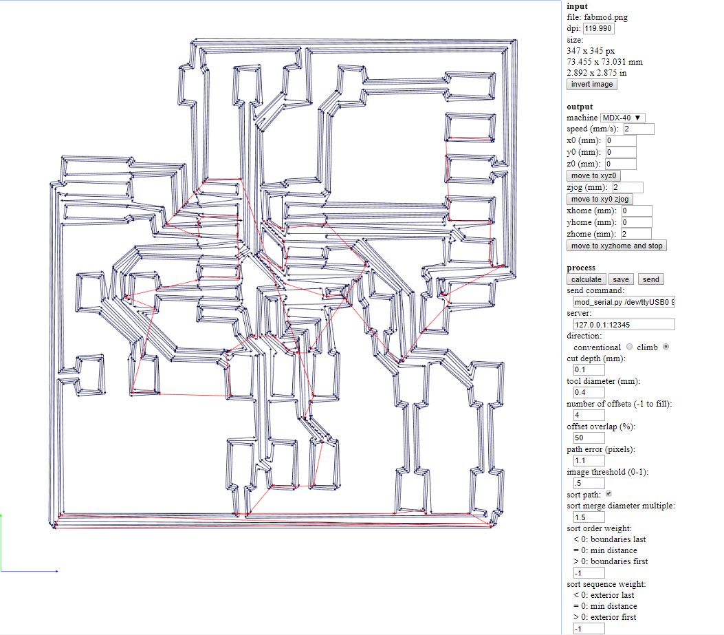
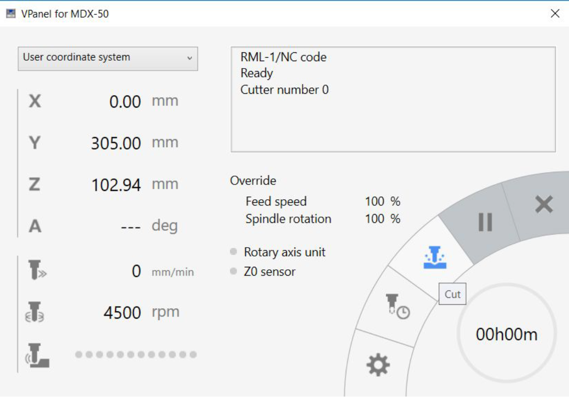
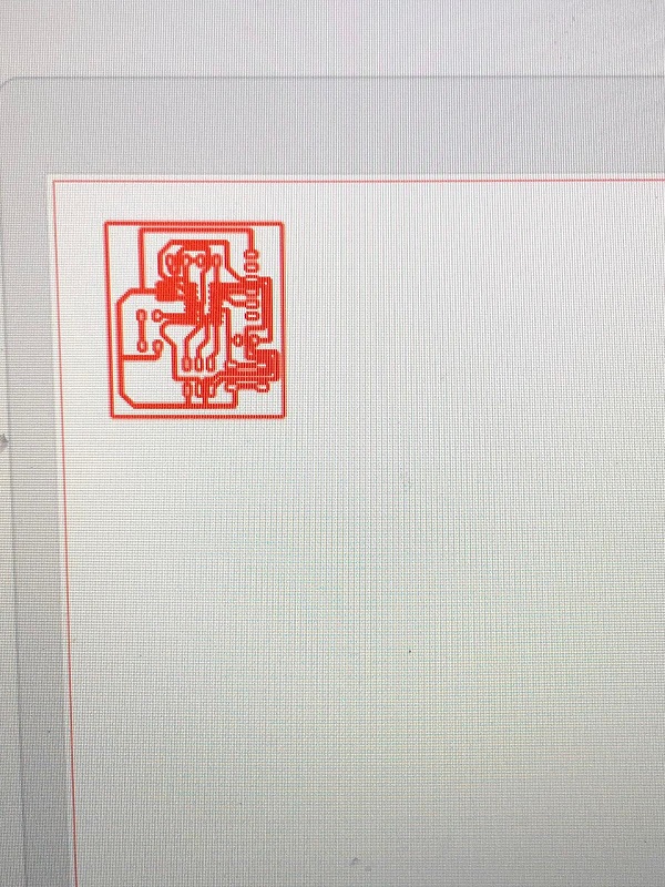
so to make the pcb i worked on Roland MDX-50. but before that i took the image to fabmodules to prepare it for the machine and i set the parameters as it appers below.after that i just uploded to vpanel by chossing the cut option and selecting the file. i homed the machine from where i want it to start. and loaded the proper tool for the operation which is V-tool.
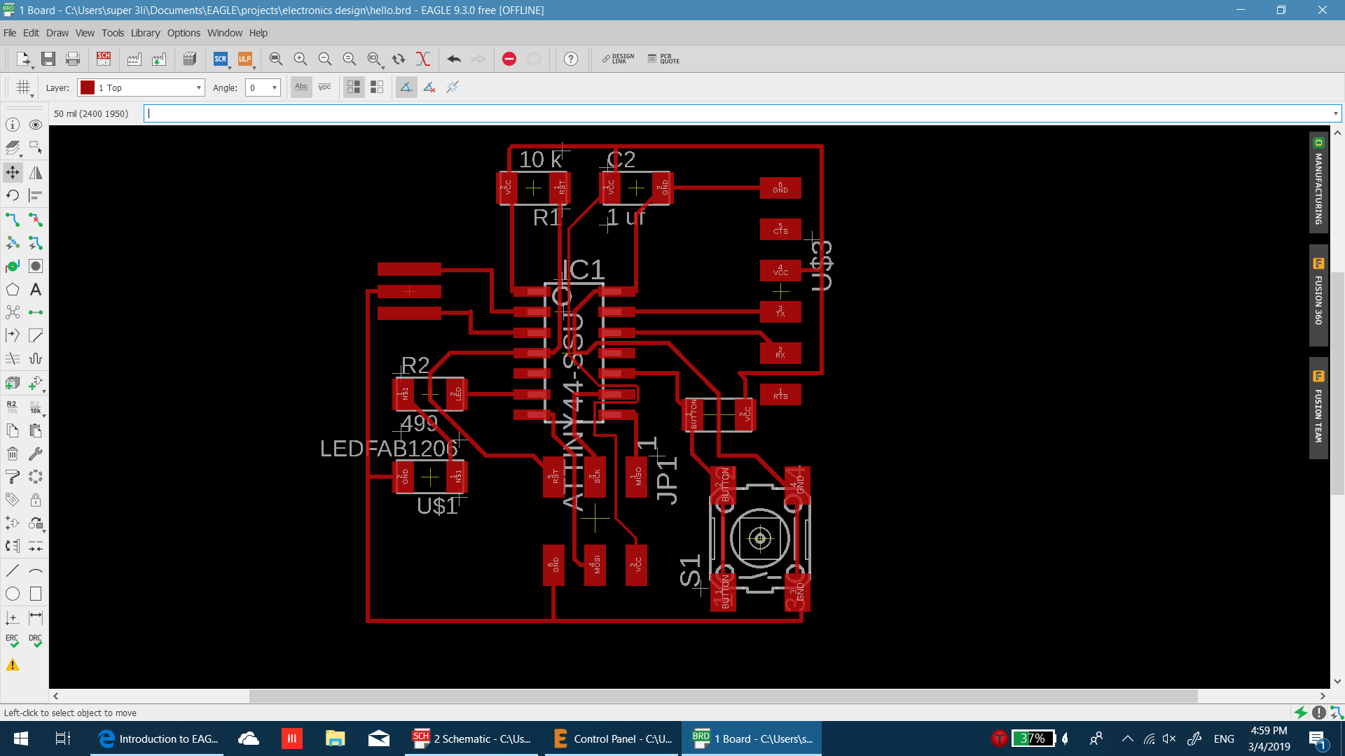
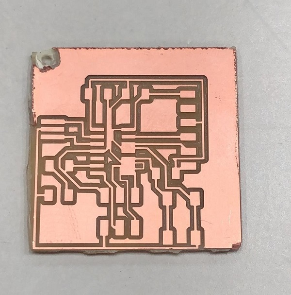
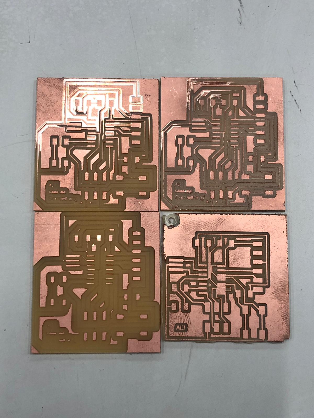
the milling went wrong ig got short circuit in alot of palces. i think its because i used very thing trace width in eagle. i used 5 for the thin lines and 12 for the thick lines. the other thing i used v tool in the milling process. although it leave a neat surface but most of the traces are not complete.
i reapeated the process with 1/64 tool but unfortunatly after many attempets every time i would get something wrong.
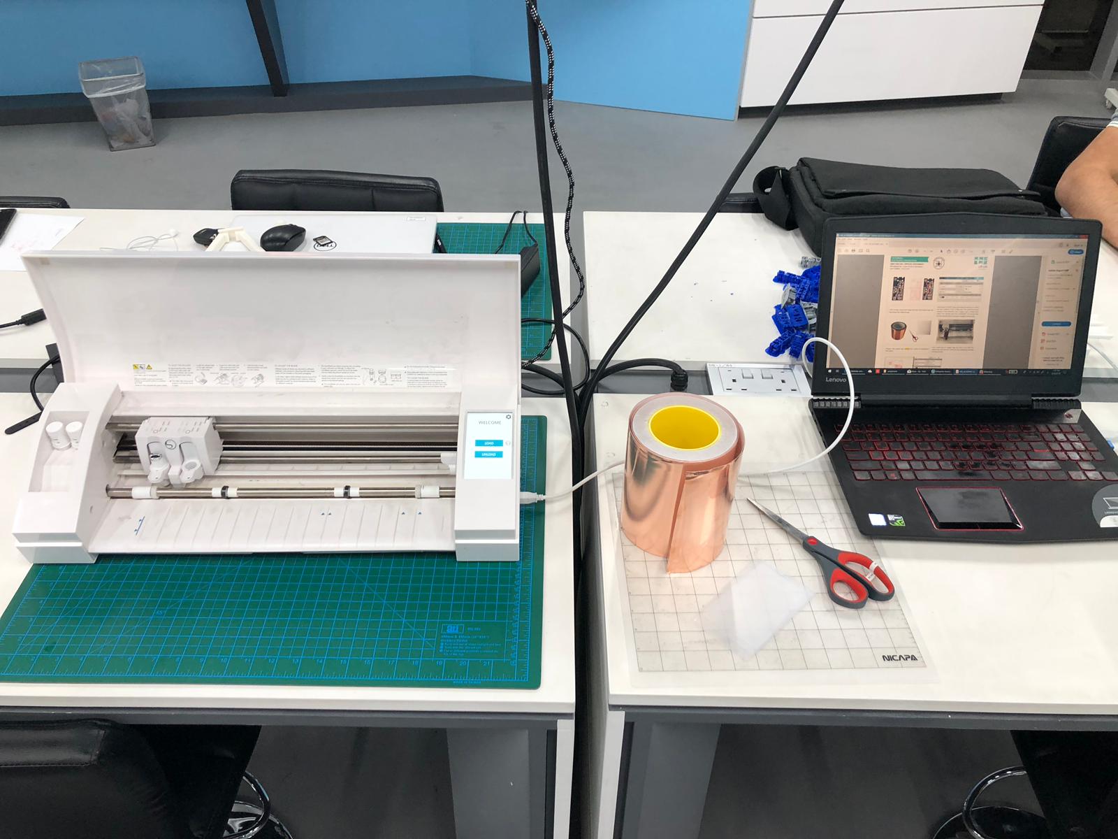
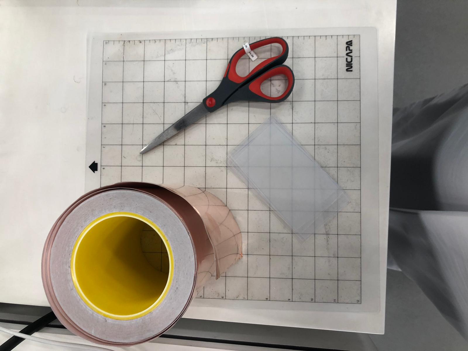
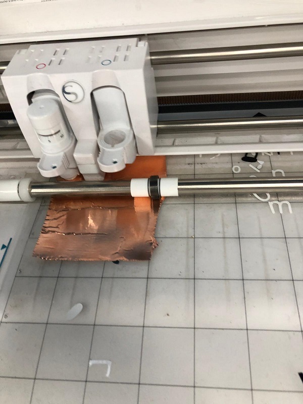
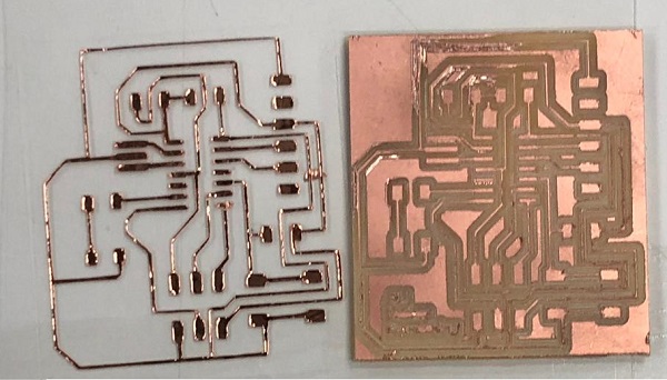
i tweeked the design a little bit and reapeated the process vynal cutter this time. i used the Silhouette cameo 3. and the software for that is the Silhouette studio. i just uploded the picture on the software i scaled it to its actual size and then chose the trace option. this got the toolpath around the traces to form the board. then i start cutting.
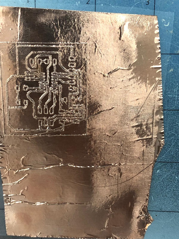
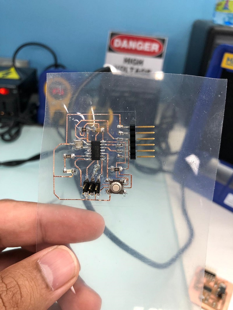
i got very beautiful board but the process of taking it out is very difficult and you need to be super carfull with it. i then started soldering the componants on the board again this was tougher then the usuall board soldering because the traces would come out if the heat is high. i somehow managed to put everything together.
