Week 7
Feb 27. Electronics Design
Group Assignment
Use the test equipment in your lab to observe the operation of a microcontroller circuit board.
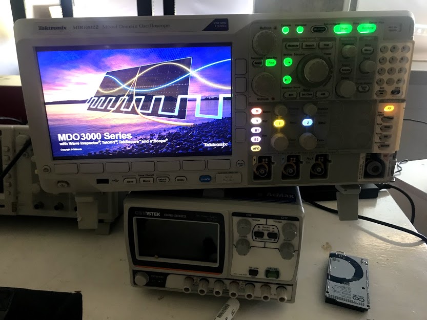
Oscilloscope
Start the oscilloscope and connect the tips.
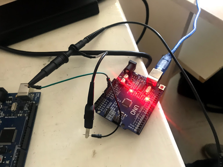
PCB to Test
Connect the tips to a PCB that will send a pulse or series of pulses.
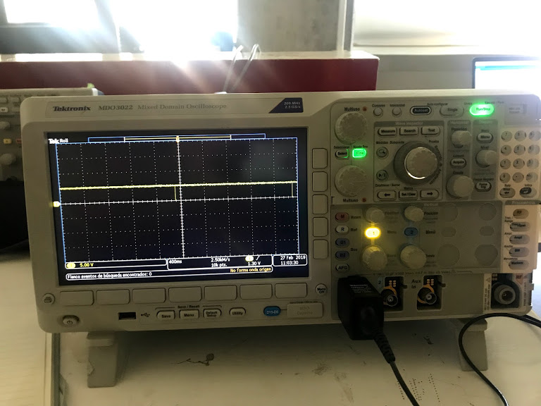
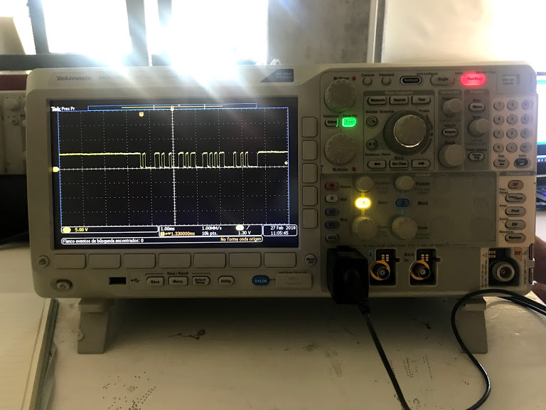
Pulse Testing
Binary pulse on screen over time.
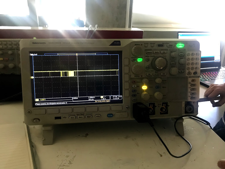
123 abc Testing
Pulse sent by a 123 abc signal.
Elongated 123 abc tesitng
Elongated sent by the 123 abc signal.
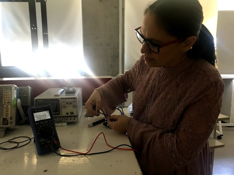
Testing Amperage
Amperage testing of a PCB with an ammeter.
Instructions
- Connect the oscillometer tips to the oscillometer
- Start the oscillometer
- Connect the tips to a PCB to test
- Send a binary pulse and observe
- Send a 123 abc pulse and observe
- Elongate in time the 123 abc wave pulse and observe
- Use an ammeter to test the amperage of the PCB's input current
Individual Assignment
Redraw the echo hello-world board, add (at least) a button and LED (with current-limiting resistor) check the design rules, make it, and test it. Extra credit: simulate its operation
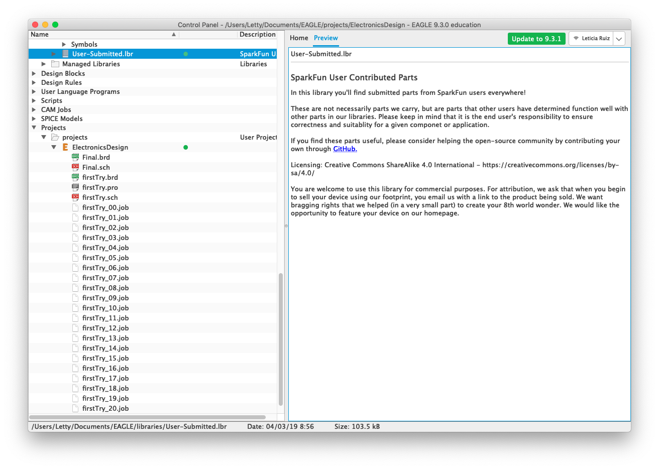
Eagle Control Panel
Add Sparkfun libraries (or any other you need) to guarantee that you have all the ocmponents in stock at your FabLab.
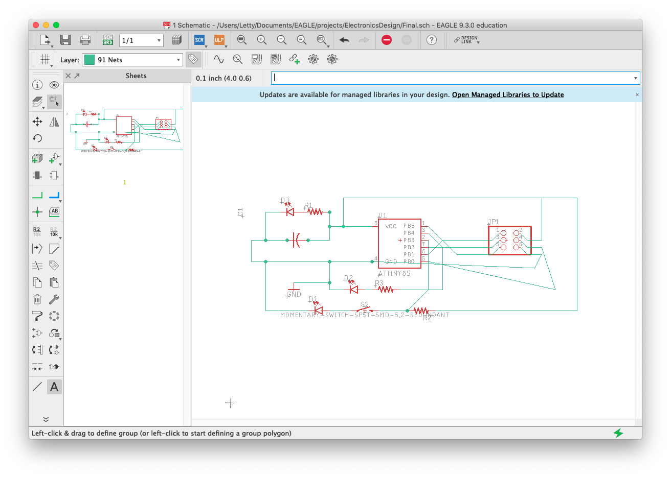
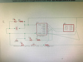
Eagle Schematic
Create your schematic trying not to cross lines to help a bit the automatic process.
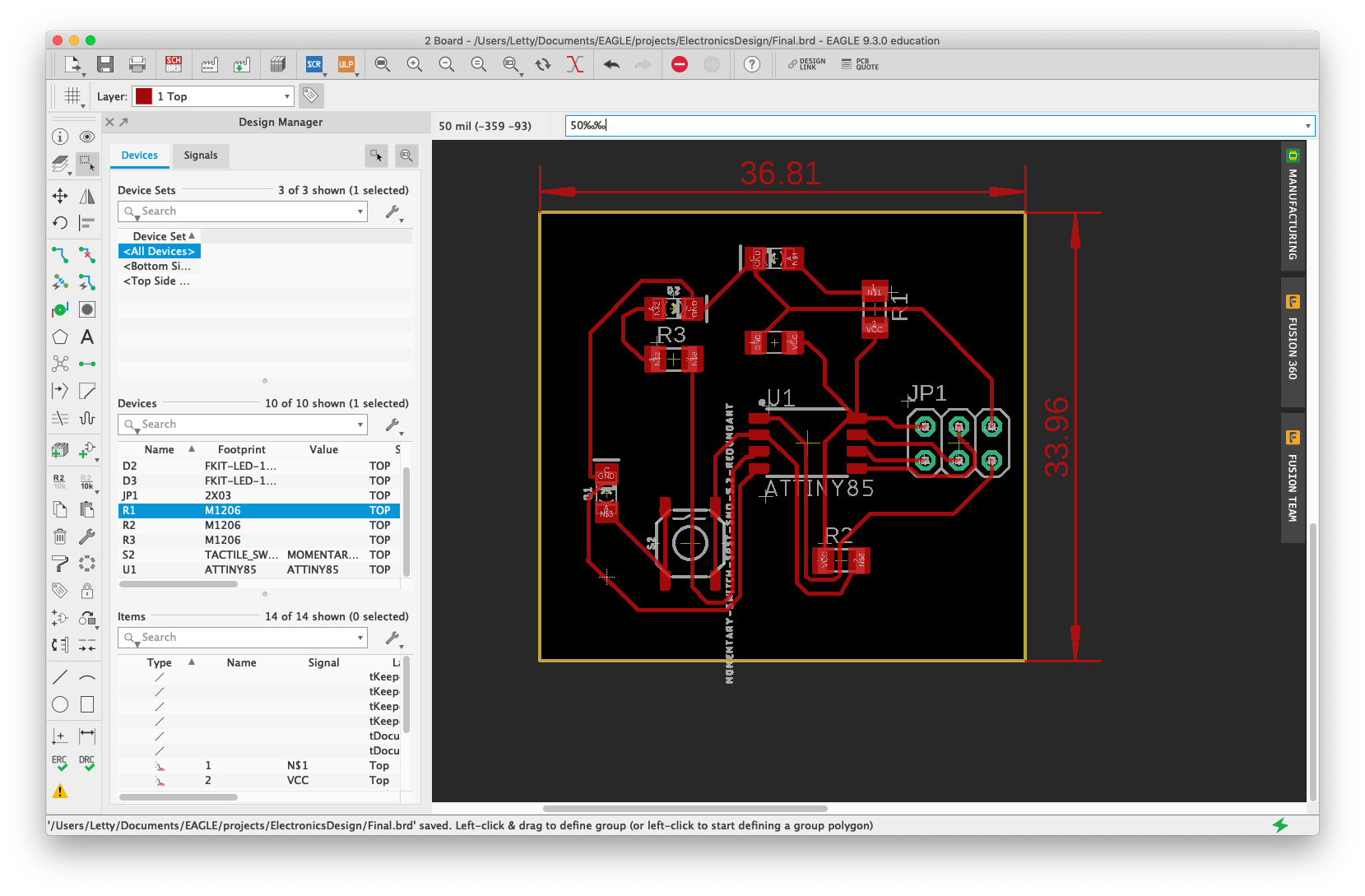
Eagle Board
Create board and include within the canvas, run the automatic line tool and correct any errors left.
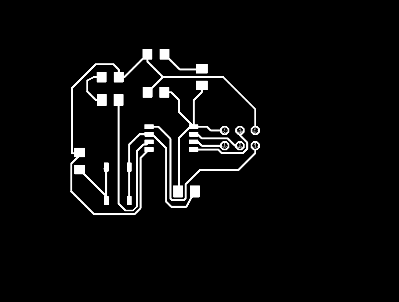
Final Inner Engraving
PNG used to created rml file to engrave.

Final Outer Cut
PNG used to create rml file to cut.
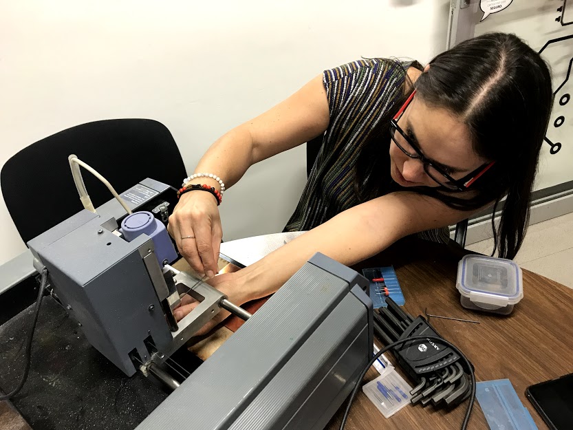
Changing Tool
Including the engraving tip on the Rolan Mill
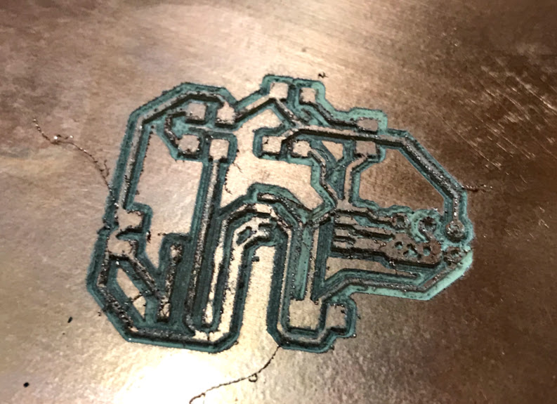
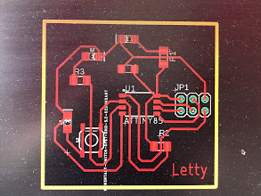
Engraved PCB
Final Engraved PCB, still a long way from being finished
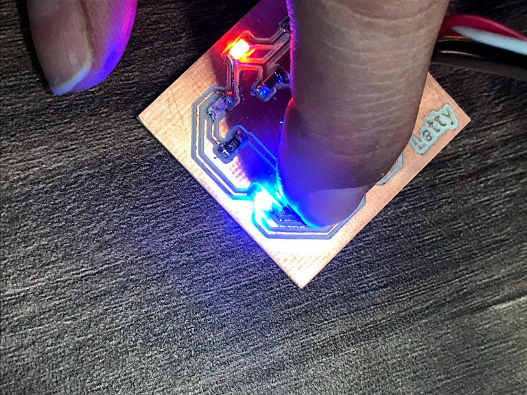
Color image
Color image of the PCB
Instructions
- Define components to be used: three LEDs, three resitors, one capacitor, one tiny45 microcontroller, 6 pin piece, one push button.
- Define your schematics on paper
- Open AutoDesk Eagle
- Look for the tiny45 microcontroller and include it in your schematics
- Add the 6 pin piece, connect to the pins you'll need
- Add the resistors and connect to VCC
- Add the LEDs after the resistors, one of them will go on when connected, another one will be programmed and the third one will be lighted by the button
- Add the capacitor rigth after VCC and on parallel with resistors
- Add the button before a LED
- Connect all components
- Go to the Board on Eagle
- Move your components into the PCB canvas (within the yellow lines)
- MOve the ocmponents as close to each other as you feel comfortable, remember you'll need to solder afterwards
- If you feel lucky try the automatic connection generator
- If you don't, move the ocmponents around (rotate, change positions, etc) to eliminate any lines crossing
- After you see very few lines crossing, or none at all, run the automatic connection generator
- Once you have zero error in the alert section you are finished (it can take several trials)
- Eliminate all the layers from the view except the top/engraving one (red) and export to image to make inner PNG
- Eliminate all the layers from the view except the dimensions one (yellow) and export to image to make the outer PNG
- Run the inner PNG by fab modules to create inner rml file
- Run outer PNG by fab modules to create outer rml file
- Run the inner rml file through the RolanMill to engrave
- Our equipment is having a bit of trouble cutting still
- We finally were able to cut using a mini mill, same process than for the Roland mill just adjusted parameteres
- After engraving and cutting the next process is solding the components following your schematics to the PCB
- Program the PCB to recognize the button and the different LEDs
- Test the PCB connected to your USBTiny previously programmed