Week 11
March 27. Input Devices
Group Assignment
Probe an input device's analog levels and digital signals

Program
we used the analogRead() function

Test
After running the program.
Test
Video of the group test.
Instructions
- Download the Arduino IDE Serial Library, this allows you to use the serial ports TX and RX.
- The serial communication speed needed for the test is 9600 bits per second
- Code a program to test the serial port
- We used an attiny45 se needed to use SoftwareSerial Library
- The main idea is to make use a macbook keyboard as the input device , by pressing the A key to turn a LED on, you can find the code in the document section of the page.
Individual Assignment
Measure something: add a sensor to a microcontroller board that you have designed and read it
 13.22.00.png)
Final Inputs Schematics
The microcontroller to be used is an Attiny85 with a magenetic sensor and a LED to verify the signal.
 13.21.41.png)
Final Inputs Board
Copper lines and component placement are marked in red and pins are depicted green. The pins correspond from left to right to 6, 5, 4, 3, 2, 1.

PCBs
Different attempts, the first one (with my name) had a short circuit, the next one I took part of the copper accidentally, the last one i sready to be soldered.

Soldered Piece
All the components have been soldered.
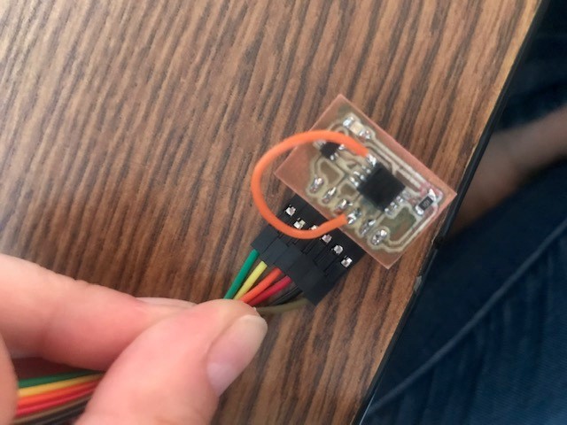
Corrected piece
After the first try I found out that I missed to connect one pin (MOSI) to the Attiny, so I connected it artificially, the files are correct now, but I didn't want to lose any time and or components making another PCB.
Video Working
After a lot of tewsting and frowning because I couldn't find the missing pin (corrected now in the files) Iit finally works.
Instructions
- Components needed:
 19.09.33.png)
- Design your input PCB, I used Eagle software
- Engrave, cut and drill the final piece, I used a mini mill
- Solder all of the components in place
- Code your test to check if your PCB works
- Compile and upload
- Test to your heart's content.
- Update:
- My first problem was actually short circuitting the first board beacuase I cabled everything wrong, so I had to do it all over again. Don't recommend it.
- My second attemp, when sanding it to take of any pieces of material I actually took more material than necessary leaving an incomplete connection, had to cut again.
- The third effort was a success! Until I realized I left a pin without connection, actually aprogramming pin. Not wanting to redesign, cut and solder a new piece (again!) I sodlered a piece of cable from the pin to the microcontroller to be able to program it.
- You would think that by now I would remeber to take a picture and video of everything, well you would guess worng, Iwas so excited to see my inputs device work that I took several videos of the actual device and none of the screen showing the data.
- The microntroller data sheet shows you which pin to use to program, which is VCC and which one is ground, by now all of my electronic pieces have used the same microcontroller, and have reused a lot of the code to test between individual assignments.
- One thing I learned is that the hall sensor can work by hardware and by software so testing the program was tricky to guarantee it was fucntioning via software.