Task 17
Machine design
In this week, I was given a task to have a group assignment. The group assignment was to actuate and automate our machine of Week 15 and to document the group project and the individual contribution. The details can be found on the group page Group Page.
Individual Contribution
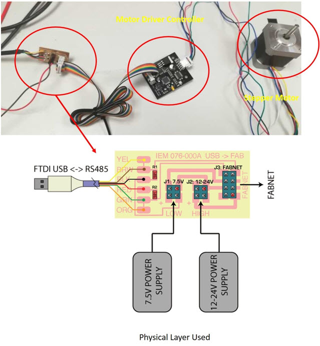
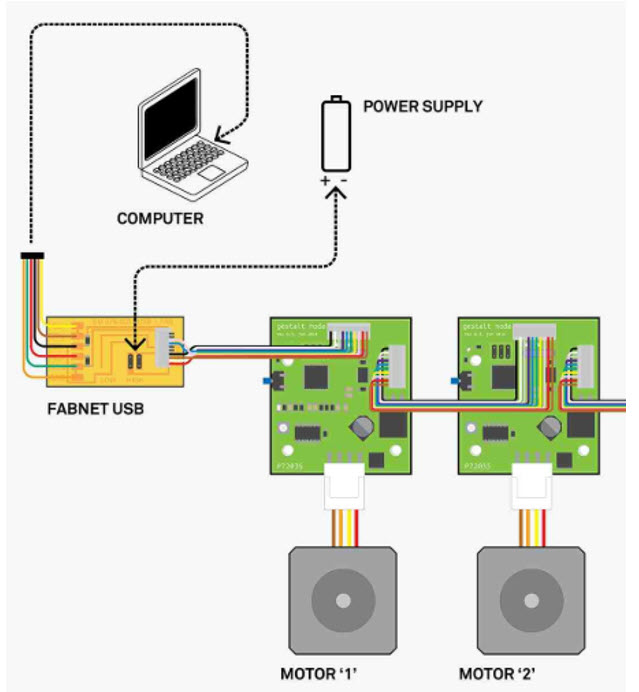
After, Alok Sethi was able to program the single node movement using the Gestalt module, I started to work on the 2 nodes movement i.e X an Y Axis seperately. The code of the single node was utlized from the gestalt module repository as the code that was given to us by Alok. The Code is simple to use and requires understanding of the necessary chnages to be made that can result in the particular direction of movement. The below pictures represent the connectivity of one node and two nodes.
Understanding and Modifying the Code
I started with the Example code and started modifying the code.
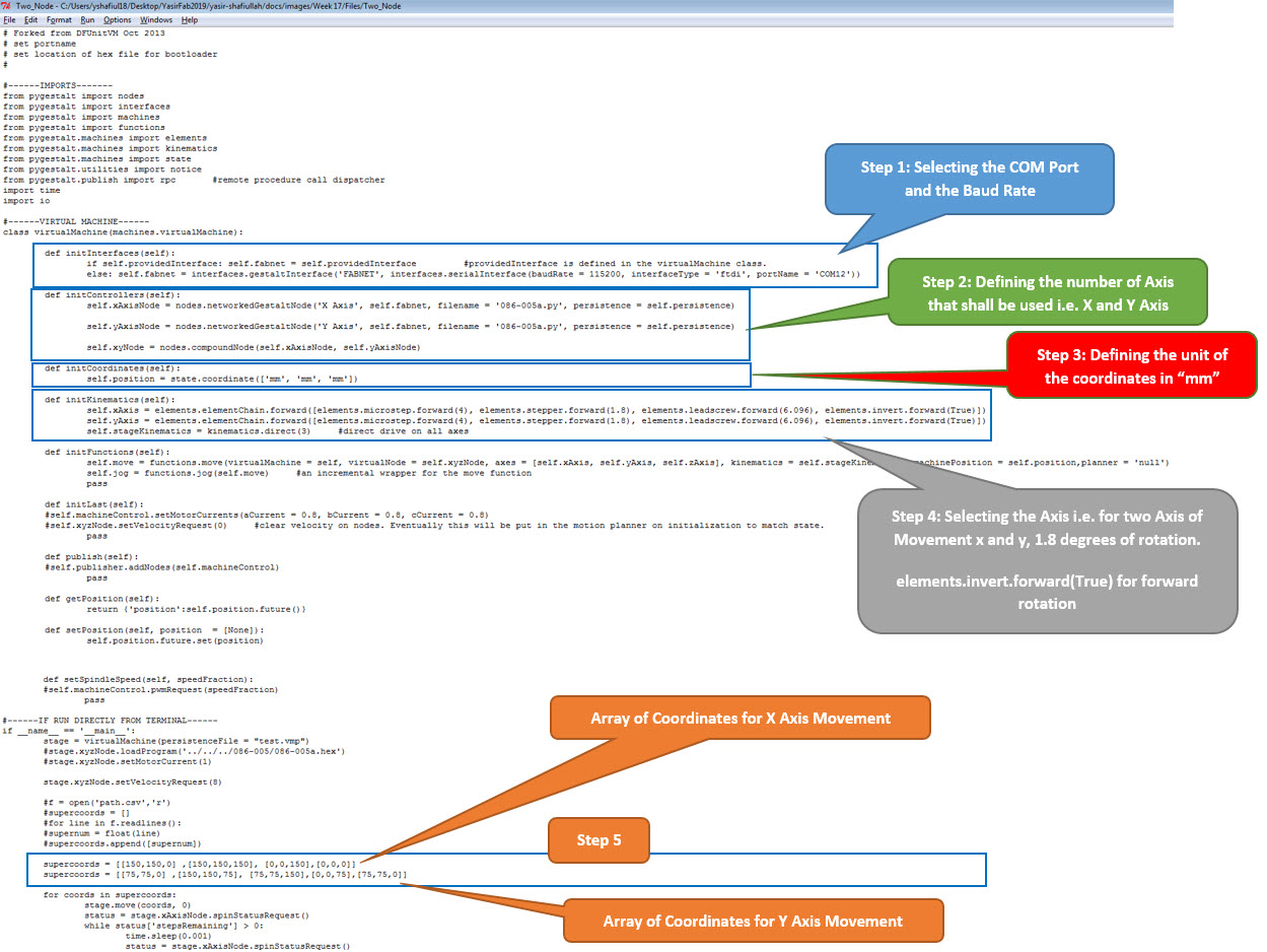
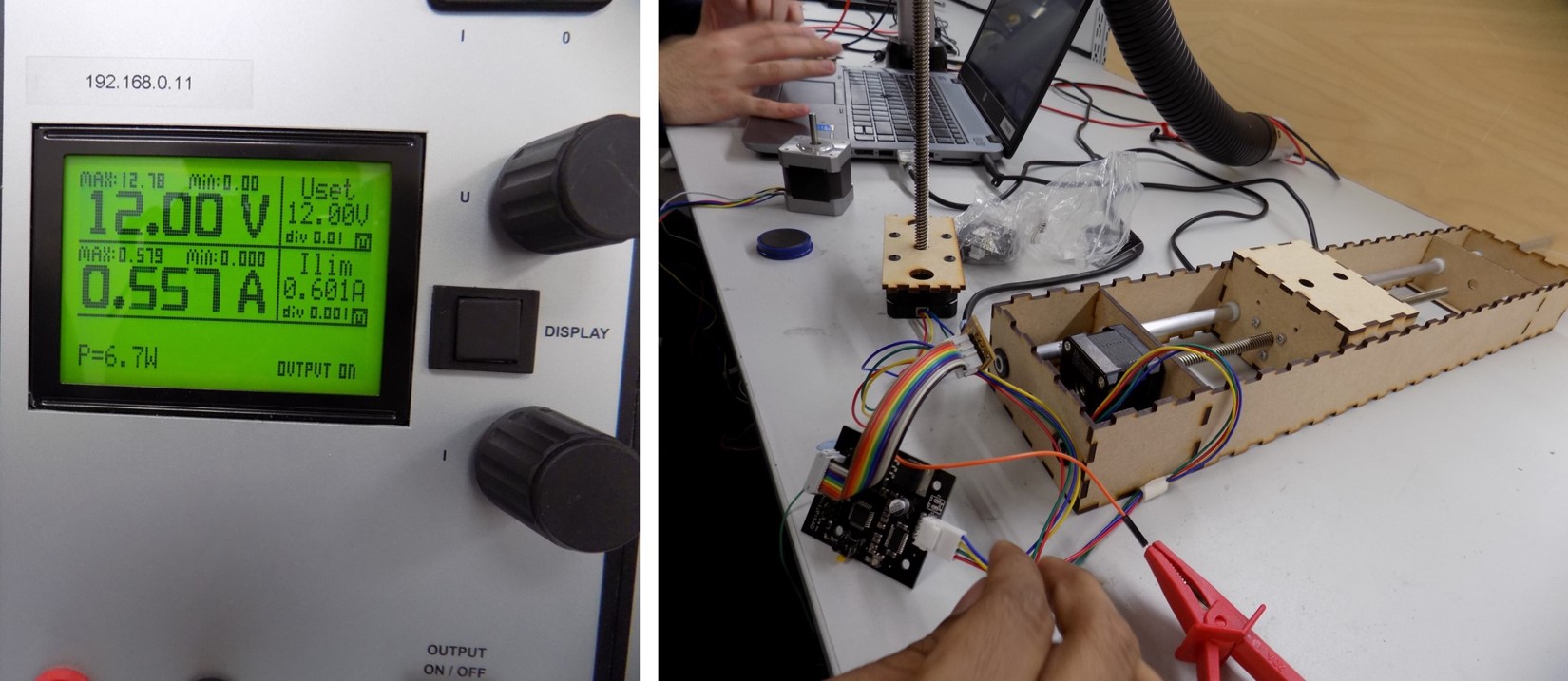
The code worked extremely fine, after couple of trial and errors it was finally a success. After the success with two nodes, Sahan moved to the next stage of modifying the code for three axis movement.
Resources Utilized
- I utilized these resources for this task:
- Python 2.7.14