Mechanical parts
Frame
Since the very beginning of the course I was thinking about the best way to make the frame. I considered laser cutting from acrylic, casting from plastic and 3d printing. After some investigation about those processes I decided to print the frame. ABS plastic seems to be a nice material for my purpose. I did all design in Autodesk Fusion 360.
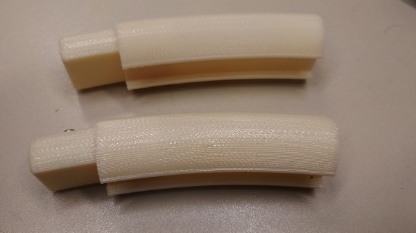
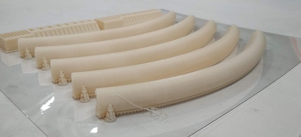
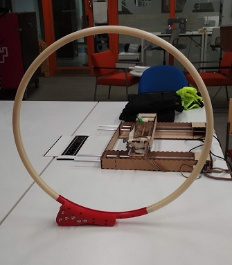
First task is to make a ring 60 sm in diameter. Revolve tool is the first thing that comes to mind. So I created a sketch of the profile I wanted with slots for LED strip and cover plastic. It's impossible to print a part so big in one piece so I divided it into six 60 degree segments. To connect the segments I created a joint with a slot for M2 nut.
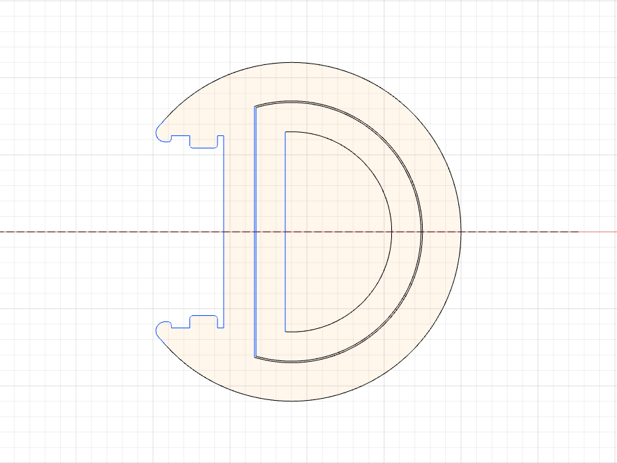
I printed a couple test pieces to check the design. First one was 20 mm in diameter and had 0.2mm tolerance in the joint. The diameter was too small and the joint wasn't so perfect. Second one was 25 mm in diameter and 0.1mm tolerance. The connection felt just great, but now it seemed to be too big. For the final print I made a file 22mm in diameter.
Mounting plate
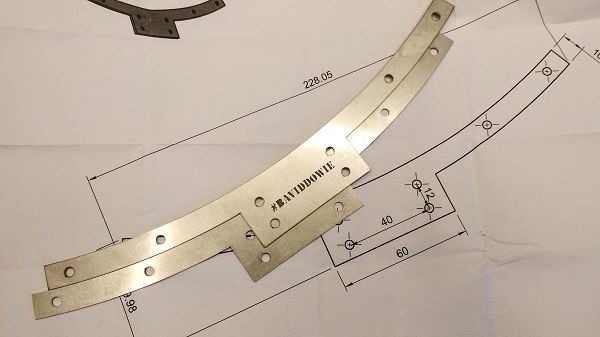
On a Wildcard week I designed and laser cut a mounting plate. It must secure the tripod mounting part. My frame will have five identical segments and one special, where all the controls will be located. Inside that part I'll attach this mounting plate with M4 screws. I was goint to use the water jet cutter and cut it from 2mm steel, but I used lasercutter insead and cut two 1mm plates.
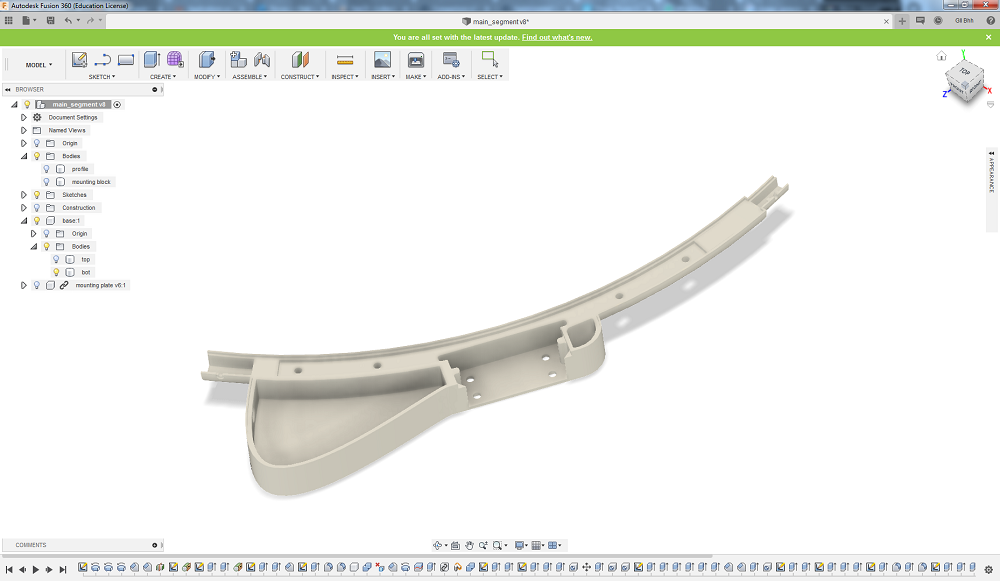
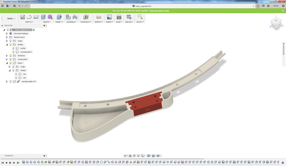
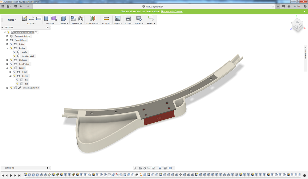
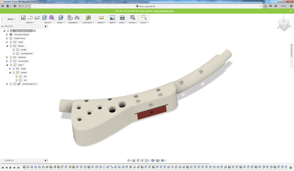
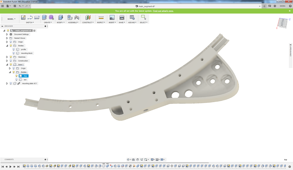
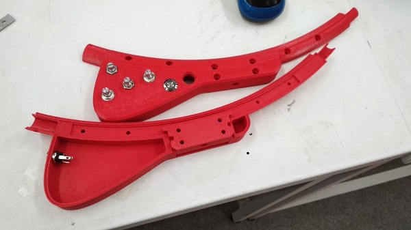
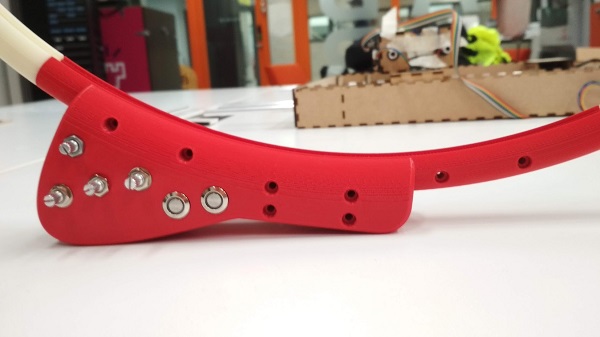
Base part
I admit, I overdesigned this part. At the end of the day the mounting plate and mounting block just made things more complicated. Now I see a better way to do this, but...
In Fusion360 I designed a base segment with a box for all electronic parts and attachment holes for the buttons and potentiometers. I saved a couple of a segment of the ring, sketched and extruded box as a new body, applied Filet to the edge next to the ring segment, combined the bodies, deleted parts of the box from the slot and using construction plane cut it in half.
Printed pats
I printed all the parts in ABS-M30 on Stratasys Fortus380 in FabLab Oulu. Total material used around 350 sm3. According to the cost of one cartridge, building sheet, and some support material it adds more then 100 EUR to the project cost. So I can cross cheap from the project features.
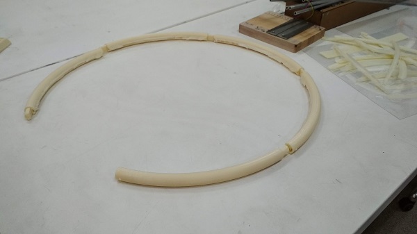
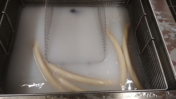
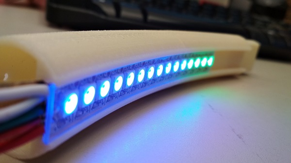
After that, I faced a problem. I tested the slot for the LED strip with a short piece. When I tried to put in the whole 257 LEDs piece, the friction was too big. So, I spent a few hours enlarging the slot. And Instead of 1mm acrylic, I got 1.2mm transparent plastic. So, the slot width wasn't so nice as it seemed to be.
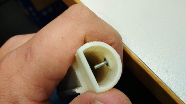
Using soldering iron I melted into plastic all metal nuts and a tripod mounting part.
Despite some problems, all mechanical parts worked as planned. I'm quite satisfied that I was able to design, print and assemble it all together.