Week 6. 3D Scanning and Printing
Go to:
1. Group Assignment
Task: Test runout, alignment, speeds, feeds, and toolpaths for your machine.
In collaboration with:
Machines used
|
|
|
Specifications
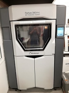
Stratasys Fortus 350mc
Technology: Fused Deposition Modeling (FDM), additive manufacturing process printing from bottom to top, layer-by-layer (each layer with each corresponding model material and support material).
Most common defect in FDM is warping: it happens when the extruded material cools during solidification, its dimensions decrease. Design considerations for preventing warping.
Solution: Avoiding large flat areas, thin protruding features and sharp corners.
Max build size: 355x305x305 mm
Typical layer height in FDM: varies between 50 and 400 microns
Material: ABS
Software: Insight
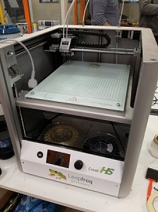
Leapfrog Creatr HS
Technology: Fused Filament Fabrication (FFF), additive manufacturing process printing from bottom to top, layer-by-layer (each layer with each corresponding model material and support material).
Most common defect in FFF is warping: it happens when the extruded material cools during solidification, its dimensions decrease. Design considerations for preventing warping.
Solution: Avoiding large flat areas, thin protruding features and sharp corners.
Max build size: 280x270x180 mm
Typical layer height in FDM: varies between 20 and 350 microns
Material: PLA
Software: slic3r
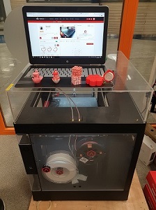
Raise3D Pro2
Technology: Fused Deposition Modeling (FDM), additive manufacturing process printing from bottom to top, layer-by-layer (each layer with each corresponding model material and support material) or Fused Filament Fabrication (FFF), printing process that uses a continuous filament of a thermoplastic material. Filament is fed from a large coil through a moving, heated printer extruder head, and is deposited on the growing work. The print head is moved under computer control to define the printed shape.
Most common defect in FDM is warping: it happens when the extruded material cools during solidification, its dimensions decrease. Design considerations for preventing warping.
Solution: Avoiding large flat areas, thin protruding features and sharp corners.
Most common defect in FFF is weakness of filaments: it happens when designed object has too thin walls/lines or nozzle is small Design considerations for preventing warping.
Solution: Avoiding thin outlines, walls and lines, use reasonable nozzle size and printing speed.
Specifications:
Max build size: 305x305x300 mm
Typical layer height in FDM: varies between 10 and 250 microns
Material: ABS
Software: Built-in
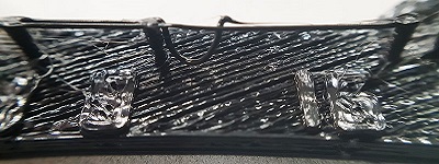
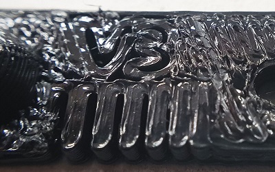
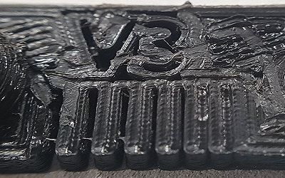
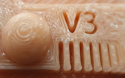
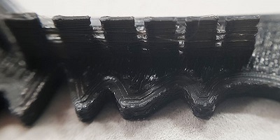
We tested our machines by printing the same test model. To make it fair we didn't print any support material.
Test parts:
1. Nut, Size M4 Nut should fit perfectly
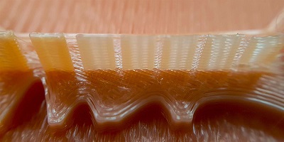
2. Wave, rounded print
3. Star, Sharp Edges
4. Name, Complex Shapes
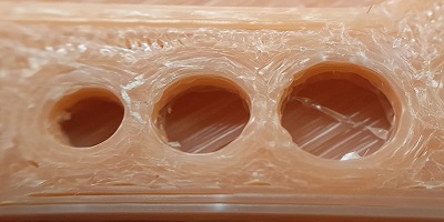
5. Holes, Size 3, 4, 5 mm
6. minimal Distance: 0.1, 0.2, 0.3, 0.4, 0.5, 0.6, 0.7 mm
7. Z height: 0.1, 0.2, 0.3, 0.4, 0.5, 0.6, 0.7, 0.8, 0.9, 1.0, 1.1 mm
8. Wall Thickness: 0.1, 0.2, 0.3, 0.4, 0.5, 0.6, 0.7 mm
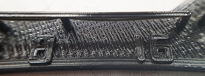
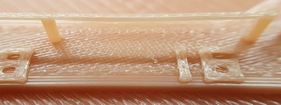
9. Bridge Print: 2, 4, 8, 16 mm
10. Sphere, Rounded Print 4.8mm height
11. Sphere Mix, 7 mm height
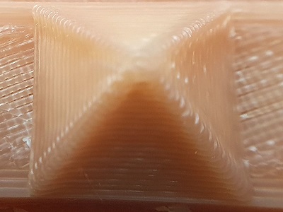
12. Pyramide, 7 mm height
13. Overhang: 25, 30, 35, 40, 45, 50, 55, 60, 65, 70°
14. Warp, does it bend?
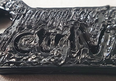
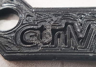
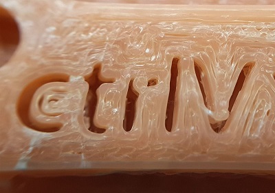
15. 3D Print Font, optimized for 3D printing
16. Surface, Flatness
17. Size, 100 x 100mm x 23.83 (10mm width)
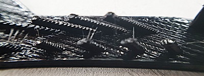
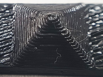
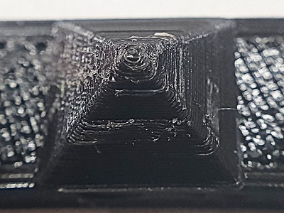
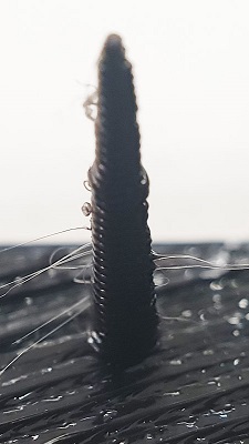
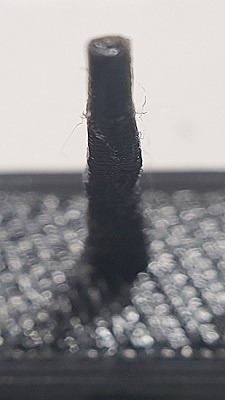
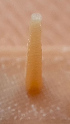
18. Spike, minimum Layer Time, 21 mm height from Bottom (include Baseplate)
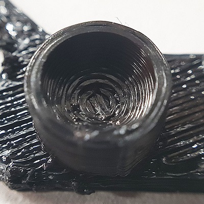
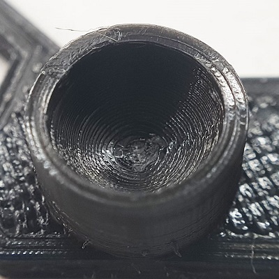
19. Hole in Wall, 4 mm diameter, check for proper print
20. Raft Test, raft should be just under the model
21. Retract Travel, check retract settings for longer travel
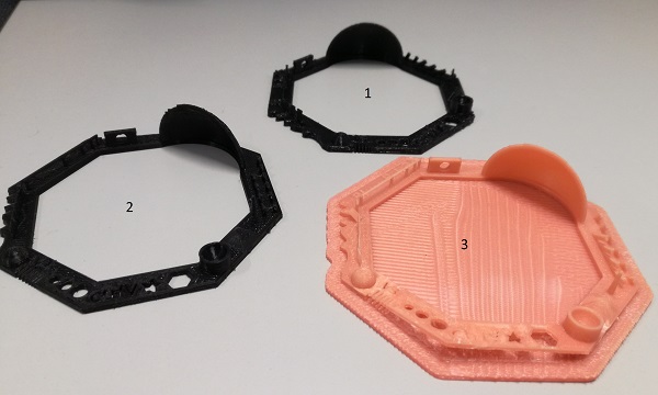
| Stratasys Fortus 380mc | Leapfrog Creatr HS | Raise3D Pro2 | |
| Material | ABS | PLA | Bulk ABS |
| Nozzle diameter | 0.4mm | 0.4mm | 0.4mm |
| Layer height | 0.254mm | 0.3mm | 0.3mm |
| Printing temperature | 200C | 200C | 250 |
| Printing time | 25min | 1 h 15min | 2 h |
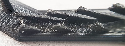
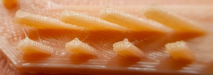
| Bridge Print |
|
|
|
| Overhang |
|
|
|
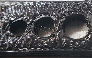
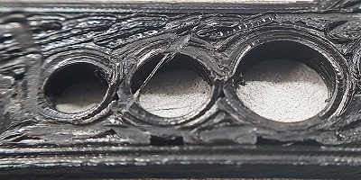
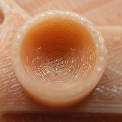
| Holes |
|
|
|
| Sphere |
|
|
|
| minimal Distance |
|
|
|
| Wall Thickness |

|
|
|
| Pyramid |
|
|
|
| Spike |
|
|
|
| Letters |
|
|
|
Raise3D Pro2 showed the best results during the tests. Leapfrog Creatr HS is on the second place and Stratasys Fortus 380mc in on the third, but it is not completely fair: a)Stratasys Fortus 380mc is designed to print with support material, b) the result is totaly different if you use a fresh building sheet. We used an old one and it affected the result, c) the purpose of this machine is a mass production at the first place. You can run this beast 24/7 and it will give you a good result.
Now, when we know the designing rule for the machines (I'm going to focus on printing Stratasys Fortus 380mc because this printer is the most used in our FabLab), I can start working the individual assignment.
2. 3D Design and 3D printing
Task: design and 3D print an object (small, few cm3, limited by printer time) that could not be made subtractively
I find Maker's Muse YouTube channel very useful and informative. For this week assignment I hardly recommend this one. I've found it after I made my design, but I really would like to print some of Angus Deveson's models.
Another inspiring video I've found after designing my piece is here. Caution! Causes immediate desire to print something!
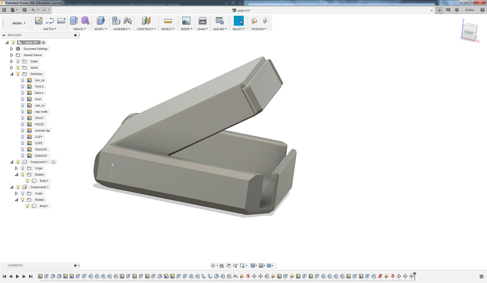
After a several hours with Fusion 360 I created a small box with a hidden pin joint. The box consists of two parts, but it can be printed in one piece. There are two round pins which create an axis of rotation on one part and holes in another. The clearance in-between the pin and the hole is 0.2mm. And there is a clip on the other side to secure the box in closed position.
This model cannot be made subtractively because of hidden pins: it is easy with printing layer by layer (with a right clearance), but totally impossible with milling process because of the joint hidden in solid stock of material.
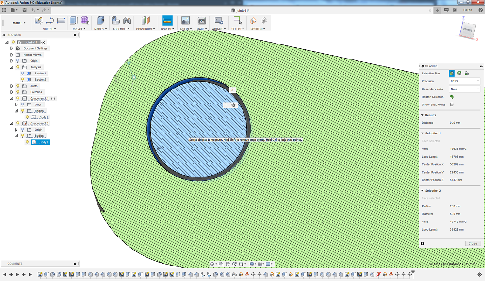
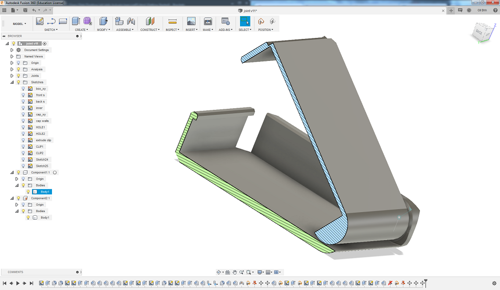
On the pictures above you can see Section Analysis tool. It is super helpful in situations like that. To use it go to Inspect/Section Analysis and choose a face which you want to inspect.
Stl model
To print the model you need to create an STL file. It's very easy in Fusion360. Go to Make/3D Print, select body or component you want to print, choose Refinement(Low/Medium/Hight) and press OK. Name and save your STL file to your computer. Optionally, you can send it to 3D Print Utility, but usually, you need to save it to memory stick and take it to 3D printer.
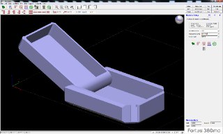
Next thing is to create a toolpath for the printer. There are multiple ways to do it, but Stratasys Fortus380 works Insight slicer (not only, but in FabLab Oulu we use this one).
There are many options in slicer. Choosing the right ones is important for a good result. My model is rather simple and small, so I chose:
Part interior style: solid
Visible surface style: enhanced
Support style: SMART (default)
There are much more options, You can scale your model, rotate it or define bottom/top face, choose infill style or support and etc.
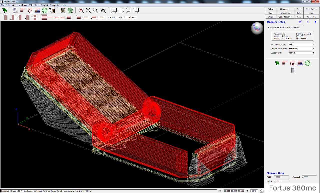
Model is ready to be printed!
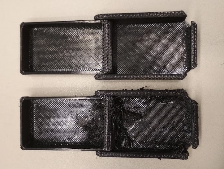
I printed two copies of my model. One of them was on unused space of building sheet and one on already used once. Guess where is which xD
This print is from my previous STL file, where the cap was placed in parallel to the main part. The slicer didn't create support material in between them and it was really hard to make the parts move as planned. But in a new file this problem is solved. Anyway, the box works as planned. It closes with a really nice click and stays closed until you pull the clip back.
3. 3D Scanning
This week I was lucky to use Kreon Ace-skyline measuring arm.
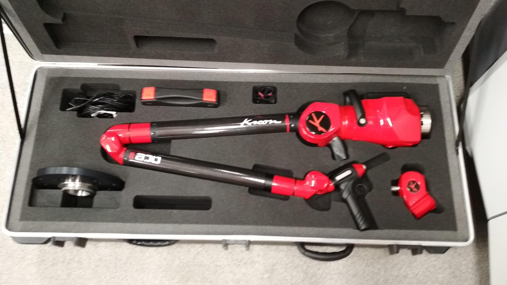
Ace Skyline combines the Ace measuring arm and the Skyline 3D scanner, providing a high performance system for contact and non contact 3D measurements. Accurate, fast, flexible…it replies to all your requirements and can scan the most challlenging parts.
*description from the official website
Speed*: 600,000 pts/sec
        Accuracy*: 09 µm
        Laser line width*: 200 mm
        Frequency*: 300 Hz
*maximum values depending on the Skyline scanner model

It is precise, accurate, fact etc., but...
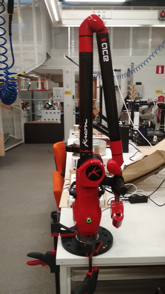
Nothing strange? Super accurate thing is just clamped to the table. To get a good result It must be super stable. When I was scanning objects, even a slight touch to the table spoiled the result. Anyway, This thing is super nice!
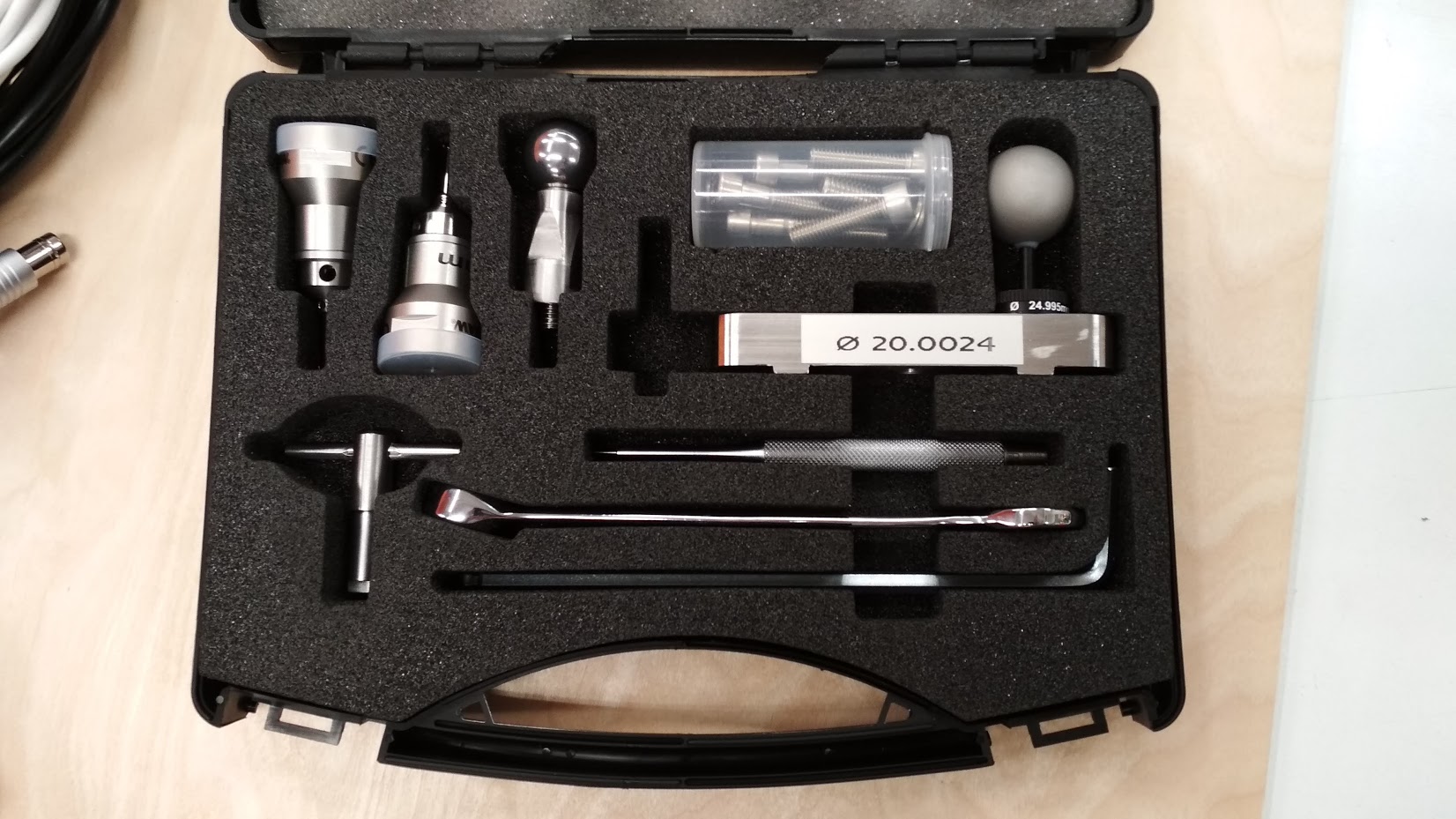
It has not only a 3D scanning nozzle, but two probe nozzeles, calibration sphere and some mounting tools.
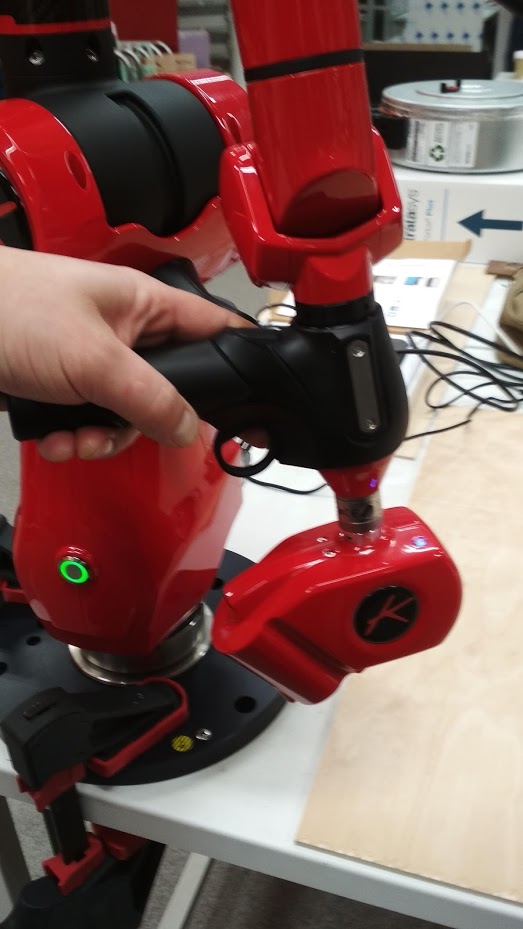
Scanning an object is easy in theory: take a pistol-shaped handle, choose the distance (it makes 3 types of sounds: too close, good, too far; feels totally like an arcade game), push the trigger and scan. With me it worked differently, but it does not mean it does not work. It's just a non perfect mounting with clamps.
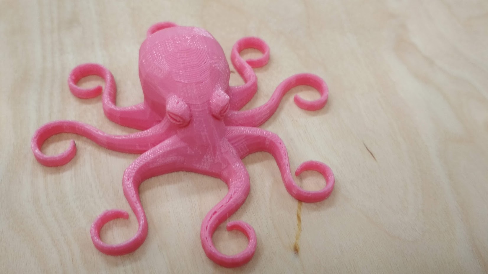
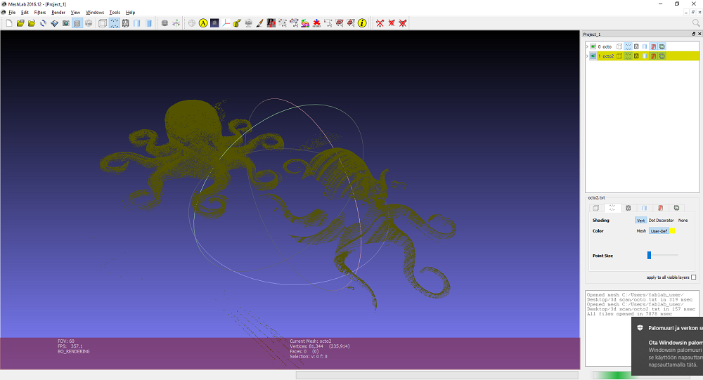
As you can see from the picutre, the point cloud I got is not dence enough to make a nice Mesh from it. But at the same time, you can see the advantage the 3D scanning technology gives us: we can transfer physical object into digital space. It can find use in very different areas: 3D printing (who will refuse a miniature model of himself, for exemple), game industry, virtual reality, different types of simulations etc. Modeling a complicated shape - if a difficult and time consuming task. 3D scanning is not so easy, but it works better and better day by day. I tried a 3D scanning app for Android as well, but I didn't really like it, so I don't want to advertise it. The idea of it is nice: you take a lot of pictures of an object from a certain distance and angles, and the app gives you a point cloud or ready mesh. The app I used had export only in the premium version. Anyway, the result I got from it does not worth publishing.
4. Results of the week
- I designed and printed a very nice and useless box
- I explored new features in Fusion360 (Section Analysis and Joint)
- I used super fancy 3D scanner
- I got super lousy 3D scan