Week 4. Computer-controlled cutting
Go to:
1. Kerf. Group assignment
Group:
Equipment:
|
|
|
Before touching laser cutter read the Manual. At least the Safety and Main features part.
Important!
- DO NOT run the Laser Unvented
- DO NOT engrave or Cut PVC or vinyl
- DO NOT run the Laser Unattended
- Check where are fire extinguisher and fire blanket (on the wall next to the sink in our FabLab Oulu)
About the machine
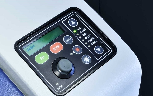
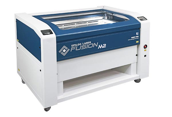
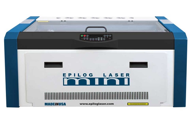
Epilog Fusion M2 40 and Epilog Mini 24 are CO2 laser cutters operating in infrared range. The cutting starts from the upper-left corner of the drawing until it's defined differently. By Up and Down buttons you can choose parameter you want to set. Then you can adjust it by joystick.
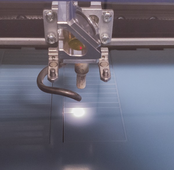
FOCUS is the distance between the laser source and the surface of the material. To set the same distance every time we use an aluminum spacer which we put on the laser source and then we lift/lower the working space until the spacer touches the surface of the material. Don't forget to press on the middle of the joystick to set the zero (if you don't do that it'll return to the zero point automatically when the cutting starts).
JOG is the position of the laser source. You can't see in infrared range (cool if you can but the most humans can't) so there's a red laser which helps to define the position of the laser source. To turn it on/off press the button with a red light pic on it. With the joystick you can move it to the position where you want start the cutting/engraving (upper left corner of the drawing) and then press on the middle to set the zero.
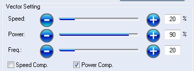
SPEED, POWER and CONFIG you can adjust here as well but it's easier to set then from the software.
File format we use for laser cutting is PDF. For the cutting the thickness of the lines must be 0.02mm (0.001"). Thicker lines will not be cut in Vector mode. To create my drawings during this week I used Inkscape and Fusion 360
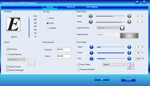
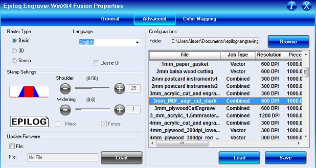
To put your drawing into cutting you need to open (the PDF file) it on the machine connected to the cutter (special driver should be installed) and press Ctrl+P and open Settings. From the General page you can choose Raster (for engraving), Vector (for cutting) or Combined (for both) mode.
Choose the Resolution as in your original image for better result.
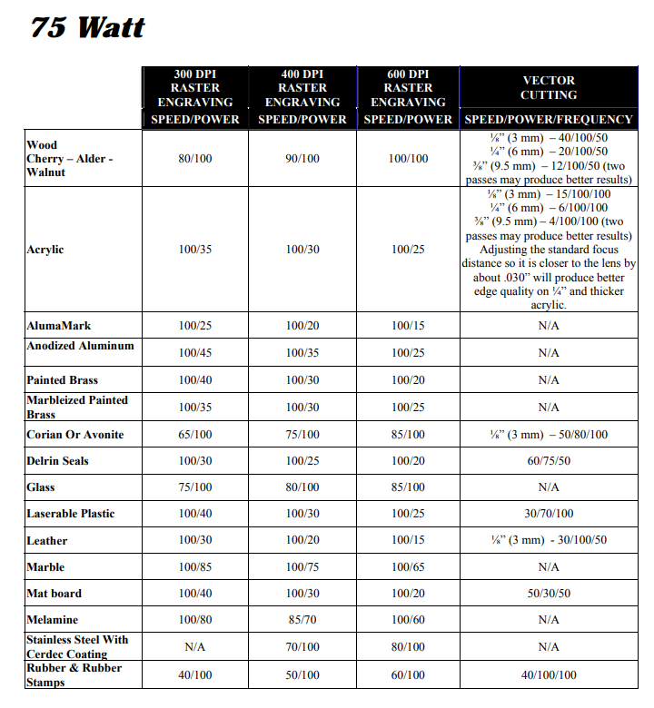
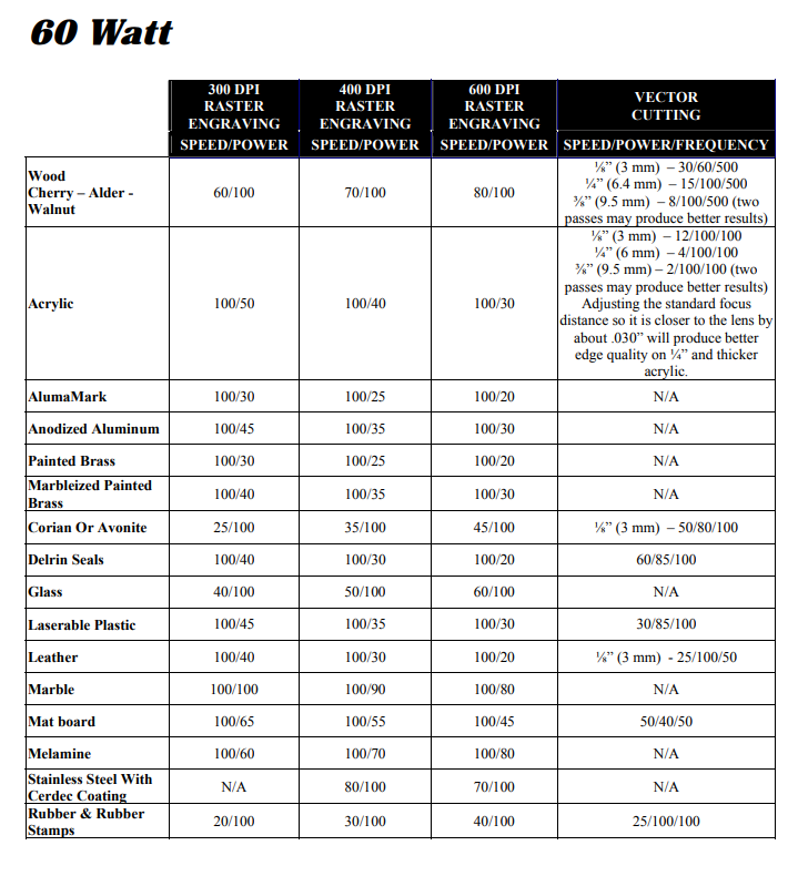
Set the Raster and Vector setting according the material. Below you can find a table with recommended parameters from the manual.
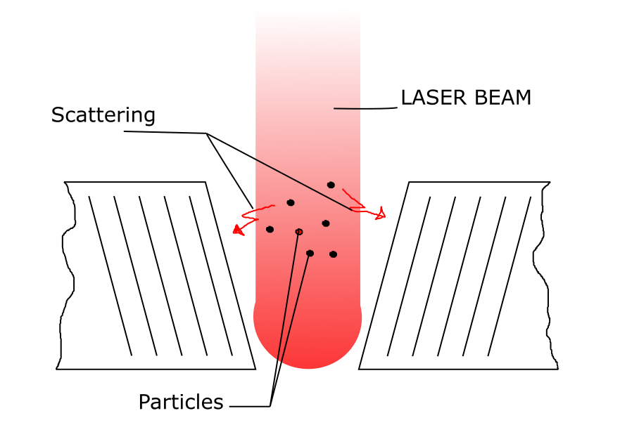
Kerf
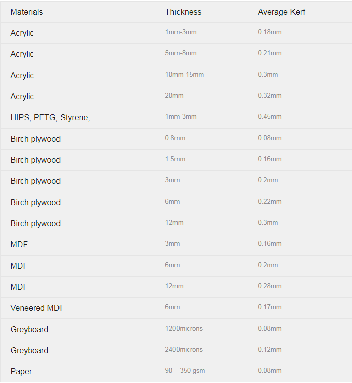
Kerf is the width of material that is removed by a cutting process. Laser beam has width. The width is minimal in focus point. There are different processes going with the material: vaporasing, burning, blasting. So some of the particles stay in the laser beam scattering it.
Kerf depends on the material, speed, power, frequency, moon position and other parameters but there's average value for each material. It's important to take account of kerf in the drawing. You can use the offset tool or make a Parametric Design
|
|
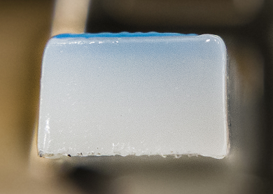
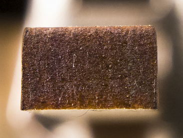
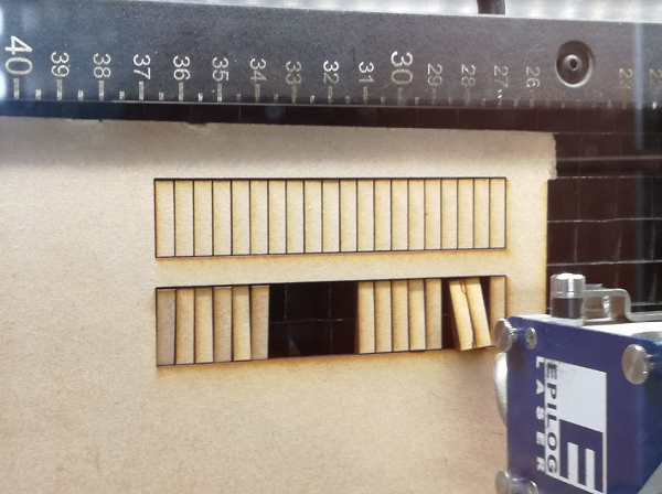
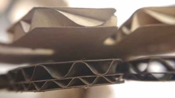
Here you can see that the upper part of the cut piece is slightly smaller than lower.
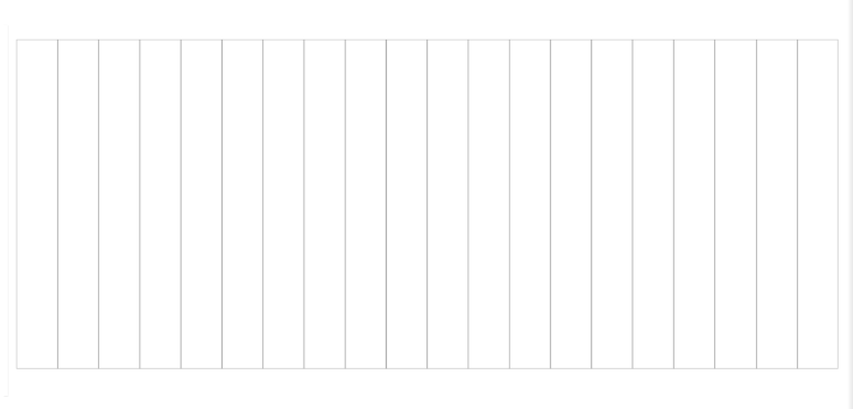
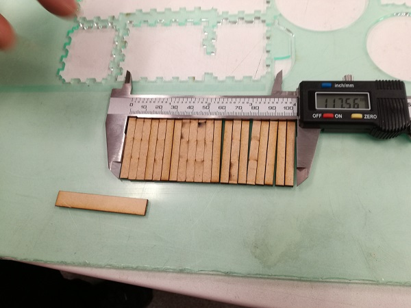
To measure the Kerf we decided to cut 20 small pieces and measure them all together. The difference between measured number and the number in the drawing will be Kerf*20. We chose 3mm Acrylic and 3mm MDF as our test samples. We used Inkscape to make a simple drawing. The drawing is a rectangle 100x40mm devided in 20 5x40mm pieces.
To measure the Kerf we decided to cut 20 small pieces and measure them all together. The difference between measured number and the number in the drawing will be Kerf*20. We chose 3mm Acrylic and 3mm MDF as our test samples. We used Inkscape to make a simple drawing. The drawing is a rectangle 100x40mm devided in 20 5x40mm pieces.
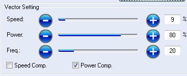
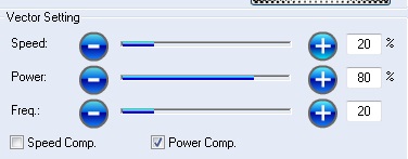
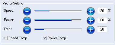
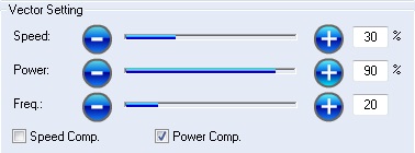
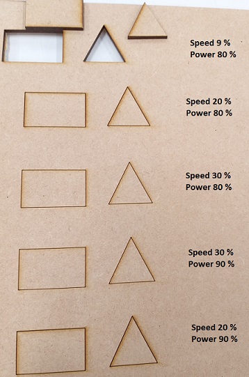
Comparing Speed and Power
We had a simple design created with Inkscape and saved as pdf for the cutting, 0,02 mm line width. We used 3 mm MDF.
2. Parametric Design
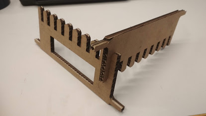
I started by drawing a test pice in Inkscare just to test the pressfit joint. The design is a crest with 0.1mm step between teeth. I cut it from 6,5 mm cardboad and it was the first issue. 6,5 mm cardboard was a tough guy. I failed to cut it 5-6 times. I even removed numbers from the drawing because the laser just burned areas with a small details (even with power compression on).
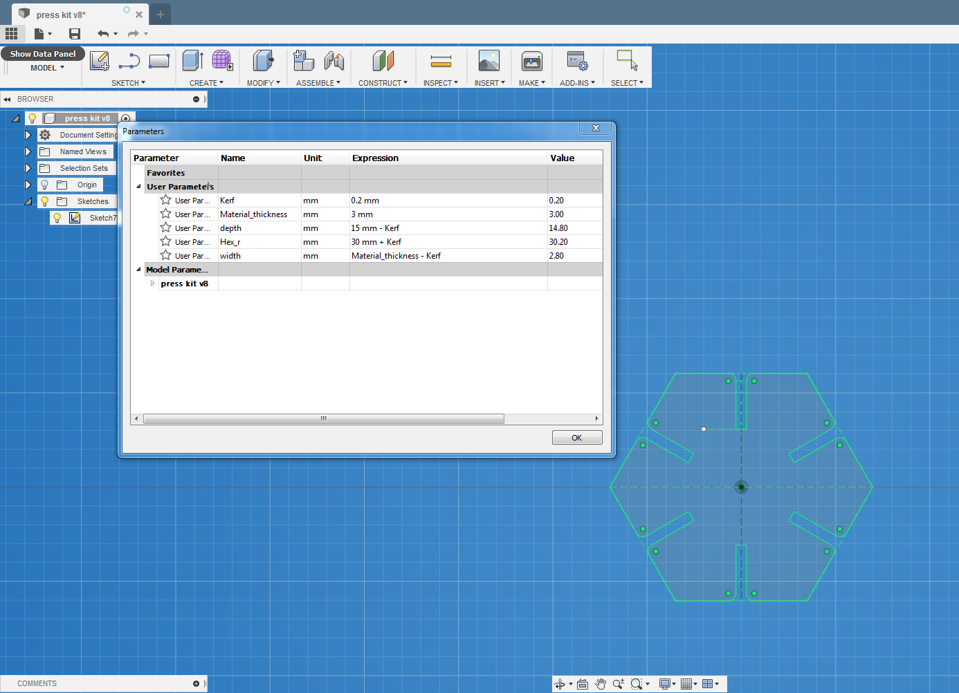
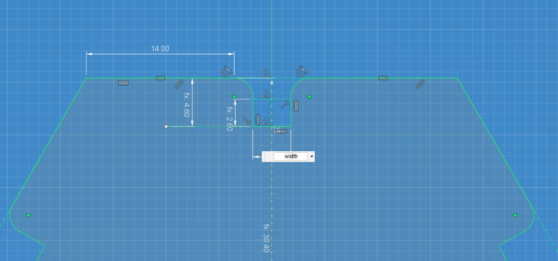
I used Fusion 360 to make the design for this week. I've like Hexagonal form so i had an idea how to start. After only 11-12 attemps I drew a proper sketch where I could change parameters of my piece.
Parameters in my design:
- Kerf - set according to the material
- Material thickness - set according to the material
- Slot depth = constant value-Kerf
- Hex radius = constant value+Kerf
- Slot width = material thickness-Kerf
The constant values define the dimensions of the part. Width of the slot depends on the material thickness.
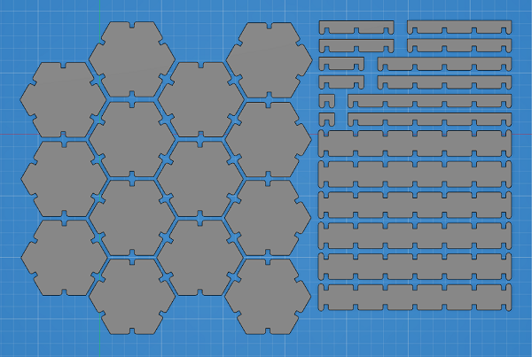
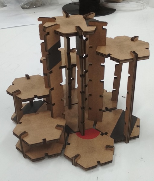
Then I created a drawing from the design and saved it as a PDF file (unmark lineweigth) for lasercutting. And I cut it from 3mm MDF on the Epilog Fusion M2 40 (75W). It was a perfect fit. Round corners of the joint helped to press one part into another. The connection was just right.
.jpg)
|
.jpg)
|
.jpg)
|
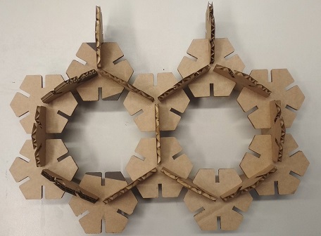
Then I found 4 mm cardboard. I changed the design by changing the parameters (kerf 0.4, material thickness 4mm, depth 15mm) and cut it as well.
3. Vinyl Cutting
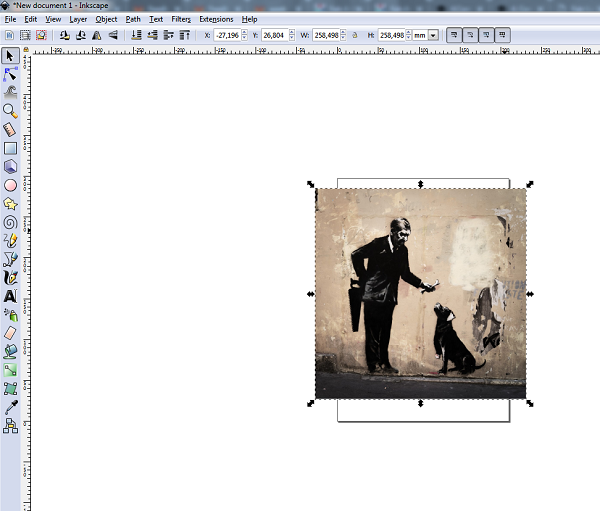
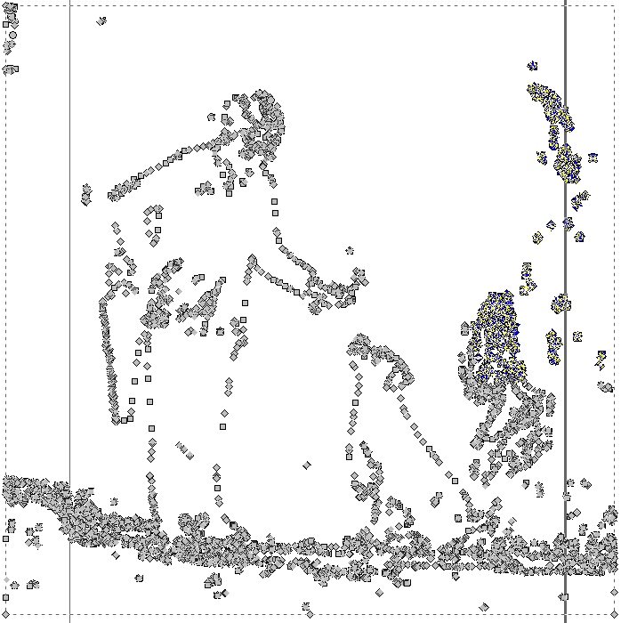
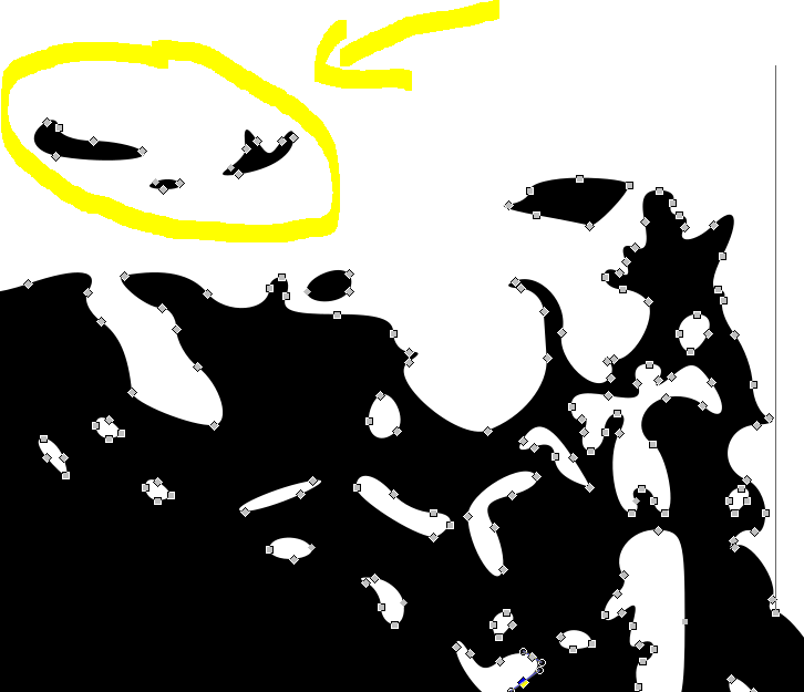
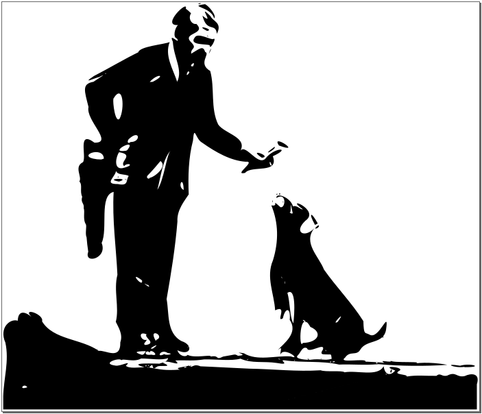
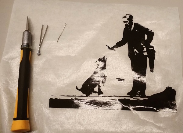
Fo vinyl cutting I decided to prepare something from a rester image. I chose a photo of a Banksys's graffity from my own collection.
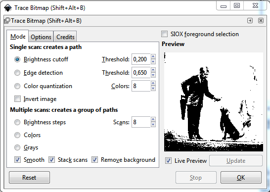
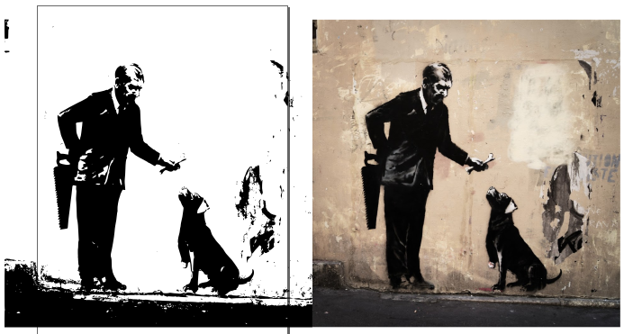
To convert a raster image into vector in Inkscape:

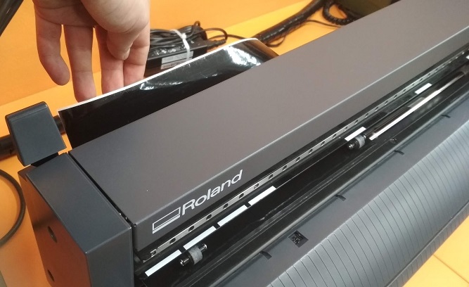
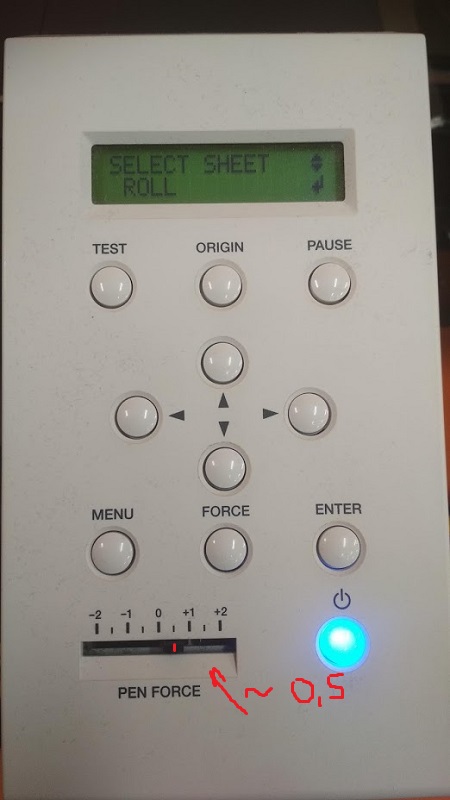
Now it's time to cut our image fron black vinyl on our Roland GS24.To cut the image
- Open the inkscape .svg file
- Open the lever on the left hand side of the machine
- Put the vinyl roll in the designated place behind the machine and put the edge in its place
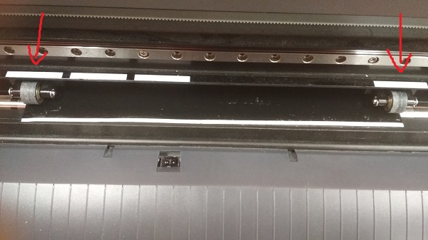
- Pinch rollers should be aligned on grit marks
- Close the lever
- Switch on the vinyl cutter.
- Choose between roll (the machine assumes you are using a big enough roll), edge (the machine will look for the edge to start) or piece. I chose Edge
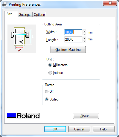
- Check the drawing is positioned on the bottom left hand corner of the document. What I actually did, was resize the document to the size of the drawing: From the Document Settings menu, click resize the document to the image size. Then, in the printer settings dialog, (shown in the image on the right), set the correct length for your case. For the width you need to keep the one given by the machine (Get from machine)
4. Results of the week
- Laser cutting is a complicated process. I got not full but good impression how the speed, power and frequncy affect the result. Now, if there are any issues with the lasercutting process I can adjust the setting for the current job.
- Vinyl cutting is a little bit less complicated, but realy fun process. I learned how to make a vector image from a raster.
- Vectorasing raster image is a nice but not 100% precise process. But it was fun to try it.
- Parametric design is handy, but it took a lot of time to do it properly. I'm satisfied with the result.
- It's better to cut a test piece before the main one than find out that the whole drawing isn't cut.
- The site was reworked a little bit.
- Lenovo cares about their equipment. But the cardboard from Thinkpad box doesn't suit laser cutting well.