Final Project: Stage 1
About 40% of my time during the project was predicted to be spent on the table and the gear design. Since I will be work at a relatively large scale and with the CNC machine, I want to get myself as ready as for the final design as possible. Stage 1 is mainly about prototype design and modeling. Here is a list of tasks I need to complete for this stage:
Prototype Design
Computer-Aided Design and Mechanics Design:
-Mechanics in Fusion 360 plug-in and/or Gear Generator
-CAD in Rhino
Laser Cutting:
-Prep laser cut file in Rhino and Illustrator
-Cut with 0.4mm plywood
Revising Design:
-Modify Gear Design
-More Laser Cutting
Computer-Aided Design and Mechanics Design
I began with the gear design. First, I look at the gears in the orrery I've bought. I will be basing many of the gears on this orrery, however, there are some parts I do not like 1) the sun rotates 2) the moon always faces the earth in the same direction. I talked with Saverio for more suggestions for making gears that allow: the center to stay still 2) the moon orbits around the earth and self-rotates 3) the earth self-rotates.
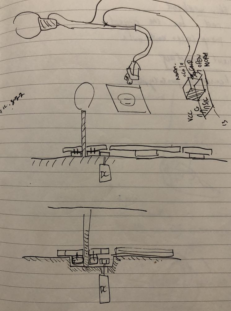
Here are some suggestions Saverio gave:
Make a two-layer gear design with:
-underneath the flat surface of the table, meaning the table has a hole in the middle that contains a box with two gears
-gear A1: its center connected to the DC motor and sends stresses to A2
-gear A2: receives force from gear A1 movement, that sends stresses to Layer 2 since gear B1 would also be moving (see below)

Layer 2:
-gear B1: glued to A2, which automatically moves at the same rate as A2; sends stresses to gear B2
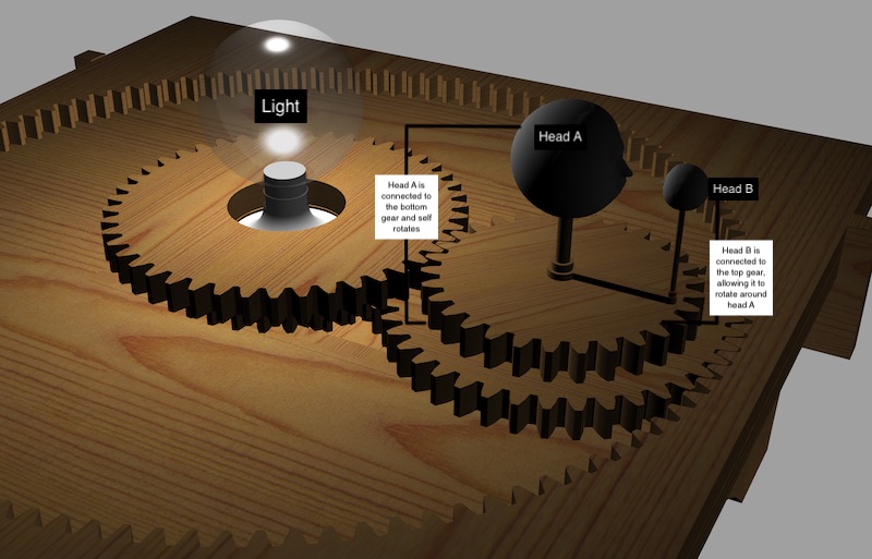
-gear B2: receive forces from B1; Head 1 (earth); sends stresses to gear B3
-gear B3: receives forces from B1; Head 2 (moon); sends stresses to the edge of the orbit (internal gear)
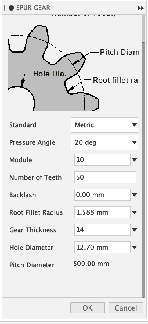
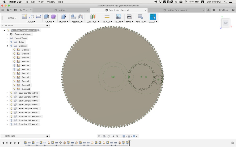
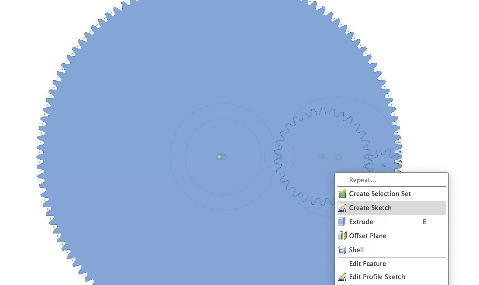
Based on the plans, I generated gears using a fusion plug-in called Spurgear based on a 600mm*600mm table top. Every time I generated a gear, I Right Click on the gear/Create Sketch to save the outline of the gear as .dxf for adapting it into my CAD.
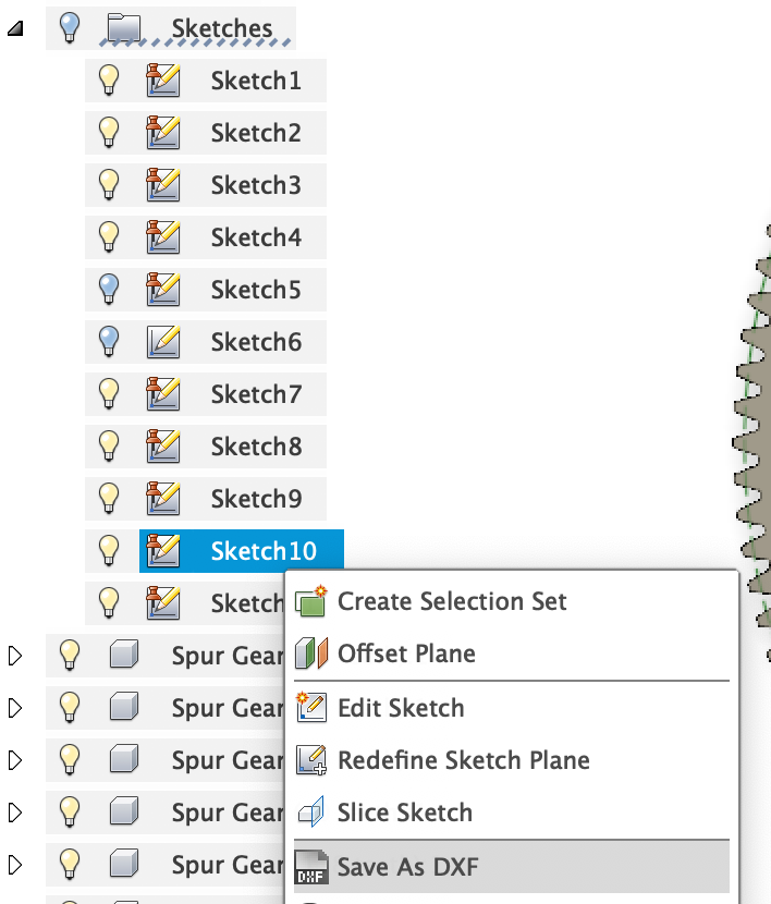
Working from the gear design, I designed the table. Although I already had a vision for the table design, I did some more research to narrow down the constraints for the table. Having an overview of the gear design also allow me to make my design specific to my needs. Here is the inspiration board of mine when I worked on my CAD, considering the structure of the table itself:

Design Constraints:
1. It is meditation table composed of two-layer gear; gear movement is triggered by a DC motor.
2. The first layer of the gear is underneath the table, and therefore the table needs to have an opening for placing a flat platform where the first layer can sit.
3. The position of the light bulb is fixed; the hole in the middle of the gear at the center of the table needs to
4. The meditation table comes with a kneeing platform: needs to be able to place a 450mm x 230mm cushion
5. In front of the kneeing platform comes with a pedestal in the shape of two hands (see image HERE for the shape of the hand) where the hand can rest on and also triggers the pulse sensor
6. The gear needs to have a part that fixes it in place
7. All designs are parametric (based on a sheet of 18mm-thick-plywood)
This is the first version of the CAD model:
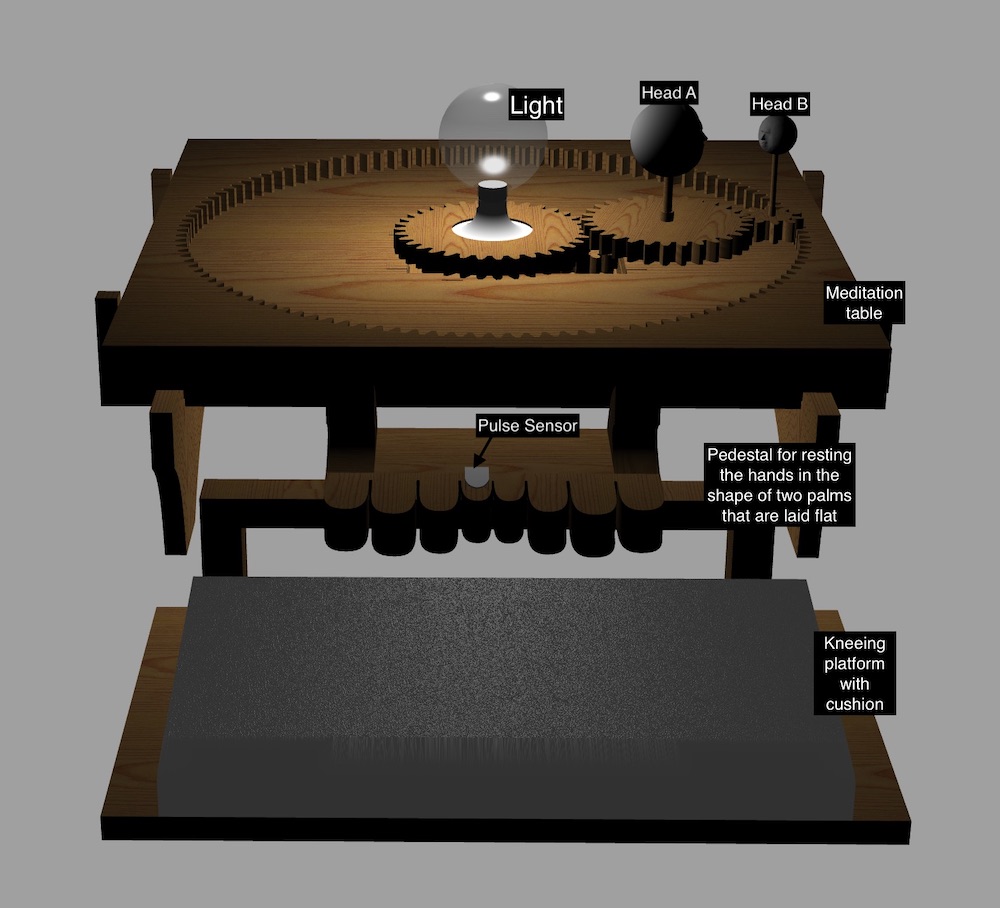

There are several problems with this current design:
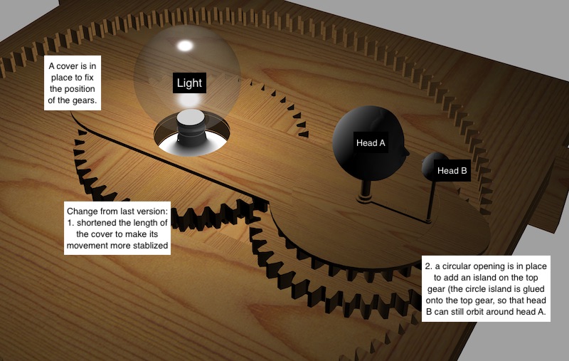
1. A bigger piece of material/cover for fixing all the gears in places is needed
2. The moon (small head) do not orbit around the earth (big head)
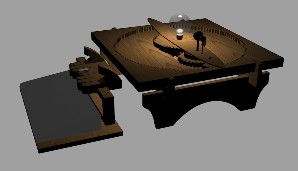
From this model, Saverio suggested me to make the gears into three-layer, with an additional layer to trigger the orbit of the moon around the earth. Here is the second CAD design, which I used to base the model laser cut file on:

Laser Cutting
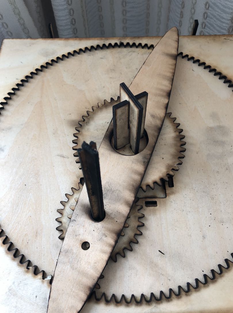
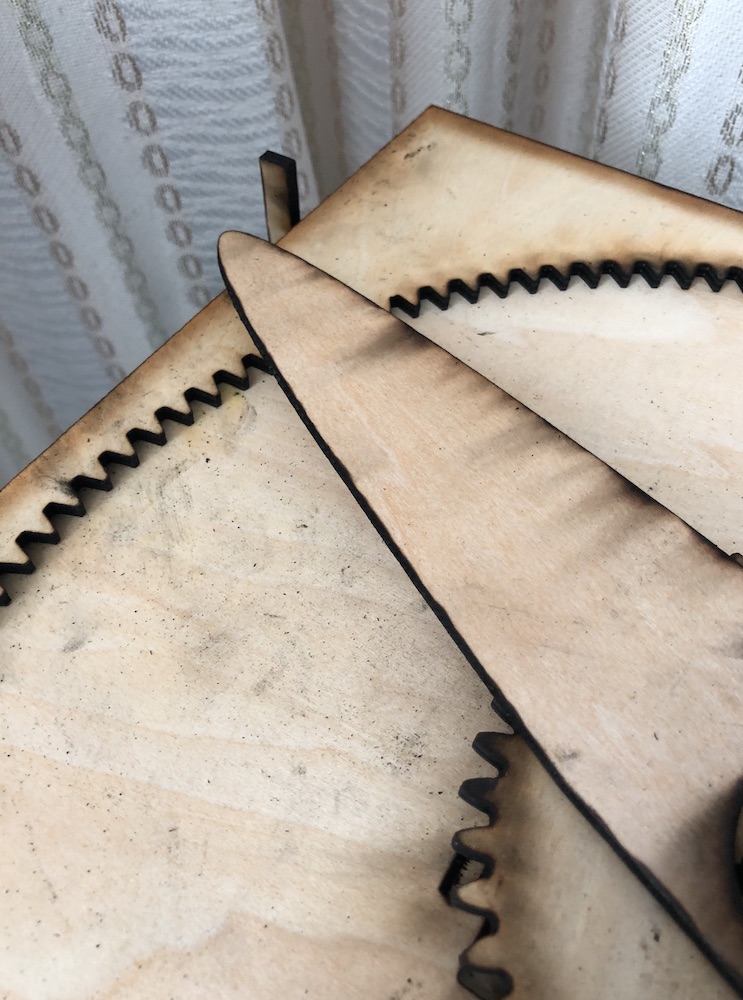
Then I made a prototype of the table by reducing the dimension of all the components in half. I made some stands as placeholders for the earth, moon and sun as well. All the design is based on a sheet of 4mm thick plywood.
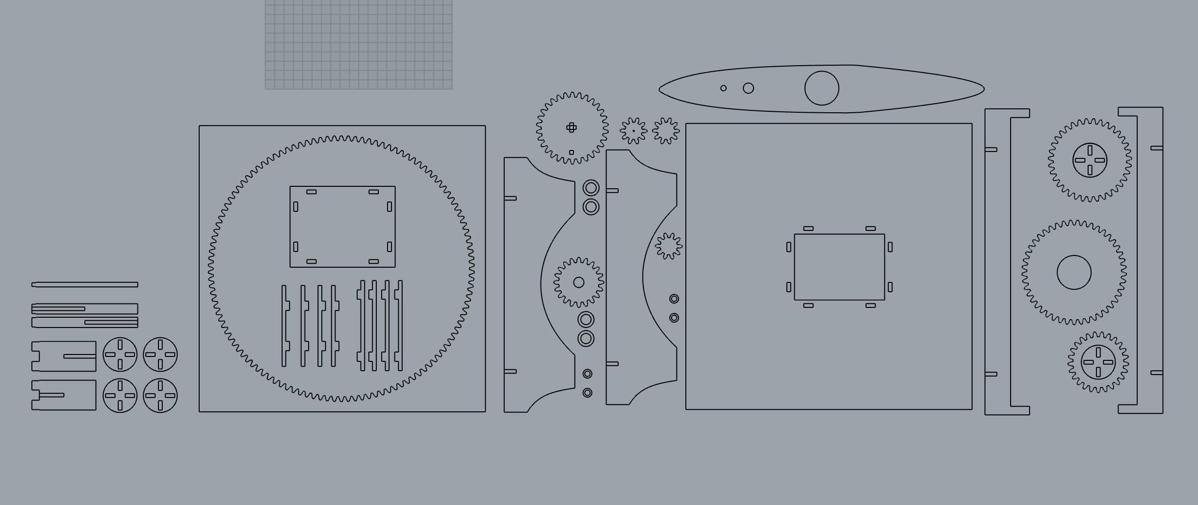
Here is the outcome... with many problems:



Problems recognized from prototype:
1. The stand for the table hits on the placeholder -> needs to be shorter
2. The placeholder is too big -> maybe out of balance on large scale
3. Made a mistake with the position of the earth and the moon
4. BUT also realized I do not need an additional gear that sends stresses to the internal gear, I can use the gear for the earth or else the space between the earth and the moon is too close
5. I made the platform for the gear at the opening too complicated; my current design is also 2x the material thickness of the gear
6. Very hard to identify where to place what gear when the DC motor hole is not drilled -> Laser 1 becomes not visible once the three layer gear is placed
Modification
Here is the second prototype, based on the problems encountered from modeling:
Second prototype in MOTION: