Week 14: Interface and application programming
The task this week is to write an application that interfaces with an input and/or output device I made few weeks ago. I am freaking out about the assignment, because I don’t relate to the beauty Neil finds in the beautiful programming languages he mentioned in class… D: Saverio mentioned to use Blynk, a mobile interface that allows to control Arduino boards without the need to have knowledge in C or Python.
How does Blynk work?
To make an application with Blynk, it is important to know the three components that are involved in the platform. Blynk App (android or IOS) is the interface for writing onto or reading from your hardware, which is my SIYUno in this case. Blynk Server is responsible for the communication between the App (smartphone) and the hardware. The Blynk libraries enables communications, commands from which are written and uploaded onto the hardware. When the hardware is connected through USB, Ethernet, Bluetooth or WiFi, commands are communicated to the Server, which activates the communication between the Blynk App and the hardware.

Turn ON/OFF an LED light
To get started, my first task is to turn ON/OFF a LED light on my SIYUno using Blynk APP. Here are the steps I have followed. I referred to Jun Kawahara's website for debugging some of the issues I have encountered during the process:
Working from Blynk APP
1. Download and sign up on the Blynk IOS APP.
2. Create a new interface, where you can select your device (Arduino UNO) and connection type (USB).
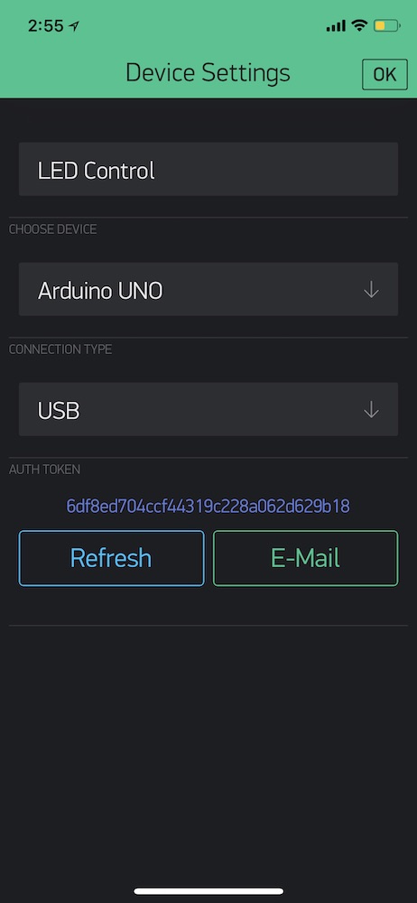
3. At this point, you will be able to see a auth token that later you will copy and paste into your Arduino code. You can send the code to your computer via Email.
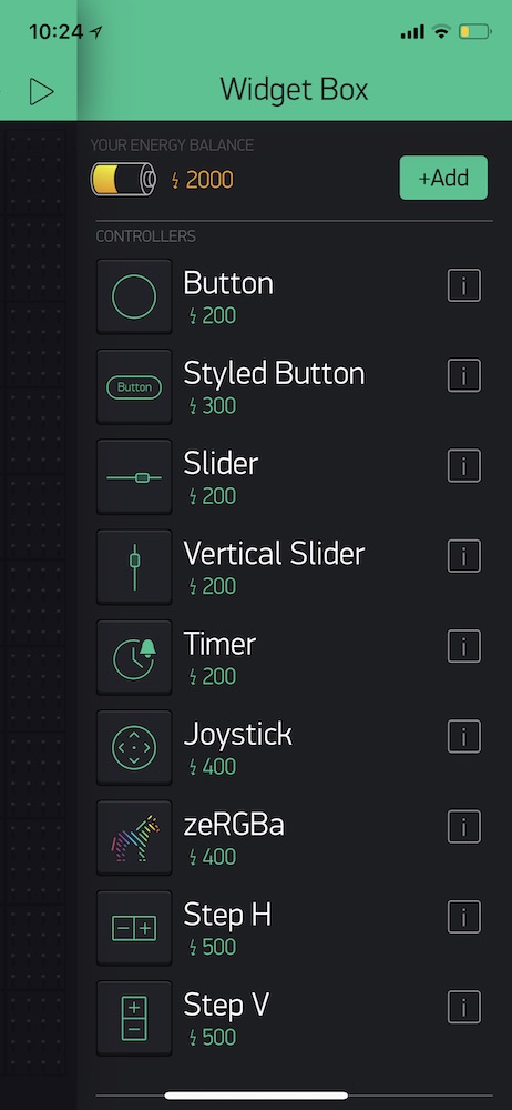
4. Under Widget Box, select Button as type of controller.
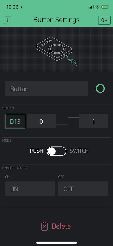
5. Click on the Button in the interface panel and set the LED output pin number, which is pin 13.
Getting SIYUNo ready
1. First, download and install the Blynk library.
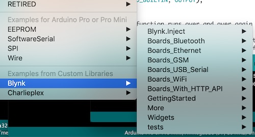
2. On THIS site, you can generate Arduino sample codes to use for your interface according to your device and connection type. Here is the code for turning ON/OFF a LED using a button from the APP.
/* Comment this out to disable prints and save space */ #define BLYNK_PRINT SwSerial #includeSoftwareSerial SwSerial(10, 11); // RX, TX #include // You should get Auth Token in the Blynk App. // Go to the Project Settings (nut icon). char auth[] = "YourAuthToken"; // Select your pin with physical button const int btnPin = 1; WidgetLED led3(V3); BlynkTimer timer; // V3 LED Widget represents the physical button state boolean btnState = false; void buttonLedWidget() { // Read button boolean isPressed = (digitalRead(btnPin) == LOW); // If state has changed... if (isPressed != btnState) { if (isPressed) { led3.on(); } else { led3.off(); } btnState = isPressed; } } void setup() { // Debug console SwSerial.begin(9600); // Blynk will work through Serial // Do not read or write this serial manually in your sketch Serial.begin(9600); Blynk.begin(Serial, auth); // Setup physical button pin (active low) pinMode(btnPin, INPUT_PULLUP); timer.setInterval(500L, buttonLedWidget); } void loop() { Blynk.run(); timer.run(); }
3. Change the auth token that was sent to you via Email.
// You should get Auth Token in the Blynk App.
// Go to the Project Settings (nut icon).
char auth[] = "YourAuthToken";
4. Push the code onto SIYUno.
Setting up for hardware over USB
1. Open Terminal and run the scripts folder from the Blynk library folder that was installed in the previous step. I've typed:
cd /Users/siyu/Documents/Arduino/libraries/scripts
2. Run
sudo sh./blynk-ser.sh
3. If
This script uses socat utility, but could not find it. Try installing it using: brew install socatappears, you will need to install homebrew, and then install socat.
NOTE: Homebrew is an opensource package management system that simplifies the process of installing softwares on MacOS system. Socat is a multi-purpose relay tool to communicate with remote Serial over TCP/IP.
4. Then, I ran the scripts again and typed the serial port I use:
Siyus-MacBook-Pro-2:scripts siyu$ sudo sh ./blynk-ser.sh
       1 ports found. You can specify port manually using -c option
-n Select serial port [ ]:
/dev/cu.SLAB_USBtoUART
Resetting device /dev/cu.SLAB_USBtoUART...
If your hardware is connected to the USB port, on the Blynk APP you device will be shown as ONLINE:
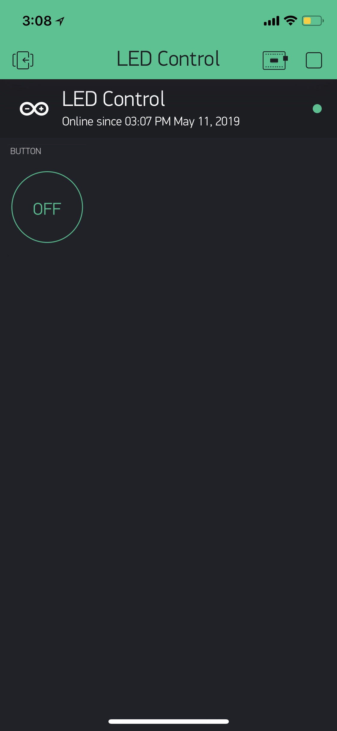
Now, the LED can be turned ON/OFF via Blynk APP:
Reading from Pulse Sensor
Then, I want to write data from a sensor onto Blynk with numerical and graphic display. I choose to use the Pulse Sensor I have used during Input Week and will be using for the final project. My goal is to have a numerical and graphic display of beats per minute (BPM). This is a task that has been done before with Blynk, but using different pulse sensor. I studied the process and the code from THIS YouTuber extensively:
#define heartratePin A0 #include "DFRobot_Heartrate.h" #define BLYNK_PRINT Serial #includeI went back to study the sample code for printing BPM through Serial Monitor with the pulse sensor I have:#include #include //including the library of SimpleTimer DFRobot_Heartrate heartrate(DIGITAL_MODE); SimpleTimer timer; char auth[] = " 0943b4b2b46c414391967788e8c0d8a0"; // You should get Auth Token in the Blynk App. // Go to the Project Settings (nut icon). char ssid[] = "Roboshala"; // Your WiFi credentials. char pass[] = "12345678"; // Set password to "" for open networks. void setup() { Serial.begin(115200); Blynk.begin(auth, ssid, pass); timer.setInterval(2000, sendUptime); } void sendUptime() { uint8_t rateValue; heartrate.getValue(heartratePin); ///< A1 foot sampled values rateValue = heartrate.getRate(); ///< Get heart rate value if(rateValue) { Serial.println(rateValue); Blynk.virtualWrite(V0,rateValue); } delay(20); } void loop() { Blynk.run(); timer.run(); }
/* Getting_BPM_to_Monitor prints the BPM to the Serial Monitor, using the least lines of code and PulseSensor Library. * Tutorial Webpage: https://pulsesensor.com/pages/getting-advanced * --------Use This Sketch To------------------------------------------ 1) Displays user's live and changing BPM, Beats Per Minute, in Arduino's native Serial Monitor. 2) Print: "♥ A HeartBeat Happened !" when a beat is detected, live. 2) Learn about using a PulseSensor Library "Object". 4) Blinks LED on PIN 13 with user's Heartbeat. --------------------------------------------------------------------*/ #define USE_ARDUINO_INTERRUPTS true // Set-up low-level interrupts for most acurate BPM math. #include// Includes the PulseSensorPlayground Library. // Variables const int PulseWire = 0; // PulseSensor PURPLE WIRE connected to ANALOG PIN 0 const int LED13 = 13; // The on-board Arduino LED, close to PIN 13. int Threshold = 550; // Determine which Signal to "count as a beat" and which to ignore. // Use the "Gettting Started Project" to fine-tune Threshold Value beyond default setting. // Otherwise leave the default "550" value. PulseSensorPlayground pulseSensor; // Creates an instance of the PulseSensorPlayground object called "pulseSensor" void setup() { Serial.begin(9600); // For Serial Monitor // Configure the PulseSensor object, by assigning our variables to it. pulseSensor.analogInput(PulseWire); pulseSensor.blinkOnPulse(LED13); //auto-magically blink Arduino's LED with heartbeat. pulseSensor.setThreshold(Threshold); // Double-check the "pulseSensor" object was created and "began" seeing a signal. if (pulseSensor.begin()) { Serial.println("We created a pulseSensor Object !"); //This prints one time at Arduino power-up, or on Arduino reset. } } void loop() { int myBPM = pulseSensor.getBeatsPerMinute(); // Calls function on our pulseSensor object that returns BPM as an "int". // "myBPM" hold this BPM value now. if (pulseSensor.sawStartOfBeat()) { // Constantly test to see if "a beat happened". Serial.println("♥ A HeartBeat Happened ! "); // If test is "true", print a message "a heartbeat happened". Serial.print("BPM: "); // Print phrase "BPM: " Serial.println(myBPM); // Print the value inside of myBPM. } delay(20); // considered best practice in a simple sketch. }
Making sure Serial Monitor reads the BPM accurately:
A few weeks ago, the number printed onto the Serial Monitor from the pulse sensor was based on the 0-1023 analog value range. This code has converted analog value into BPM with the
int myBPM = pulseSensor.getBeatsPerMinute();command at the beginning of void loop:
Based on the two codes, I modified the code to work with my SIYUno using USB Serial connection. Here is my code:
/* Comment this out to disable prints and save space */ #define BLYNK_PRINT DebugSerial #define BLYNK_PRINT Serial #define USE_ARDUINO_INTERRUPTS true // Set-up low-level interrupts for most acurate BPM math. #include// Includes the PulseSensorPlayground Library. #include //including the library of SimpleTimer #include SoftwareSerial SwSerial(0, 1); // RX, TX #include // You should get Auth Token in the Blynk App. // Go to the Project Settings (nut icon). SimpleTimer timer; char auth[] = "6df8ed704ccf44319c228a062d629b18"; // Variables const int PulseWire = A0; // PulseSensor PURPLE WIRE connected to ANALOG PIN 0 const int LED13 = 13; // The on-board Arduino LED, close to PIN 13. int Threshold = 550; // Determine which Signal to "count as a beat" and which to ignore. // Use the "Gettting Started Project" to fine-tune Threshold Value beyond default setting. // Otherwise leave the default "550" value. PulseSensorPlayground pulseSensor; // Creates an instance of the PulseSensorPlayground object called "pulseSensor" void setup() { // Debug console SwSerial.begin(9600); // Blynk will work through Serial // Do not read or write this serial manually in your sketch Serial.begin(9600); Blynk.begin(Serial, auth); // Configure the PulseSensor object, by assigning our variables to it. pulseSensor.analogInput(PulseWire); pulseSensor.blinkOnPulse(LED13); //auto-magically blink Arduino's LED with heartbeat. pulseSensor.setThreshold(Threshold); timer.setInterval(2000, sendUptime); } void sendUptime() { int myBPM = pulseSensor.getBeatsPerMinute(); // Calls function on our pulseSensor object that returns BPM as an "int". // "myBPM" hold this BPM value now. if (pulseSensor.sawStartOfBeat()) { // Constantly test to see if "a beat happened". Serial.println(myBPM); // Print the value inside of myBPM. Blynk.virtualWrite(V0,myBPM); } delay(20); } void loop() { Blynk.run(); }
I tried to upload this code onto a Shanghaino, since when I uploaded it onto siyUno successfully, Blynk still showed device offline. However, when I uploaded it onto a Shanghaino, I had the same issue. There might be some more complicated procedure that I missed out, but I was not able to figure out. I was told Blynk work well via a WiFi module like NodeMCU or ESP. I will try them out in the future.
Processing
I also try to make a LED turn on and off by making an interface on Processing. Since the structure from programming in Processing is quite similar to Arduino, it was fairly easy to get started. I began with drawing in processing following THIS tutorial.
The language of programming is based on Arduino, which allows this two softwares to synchronize easily.
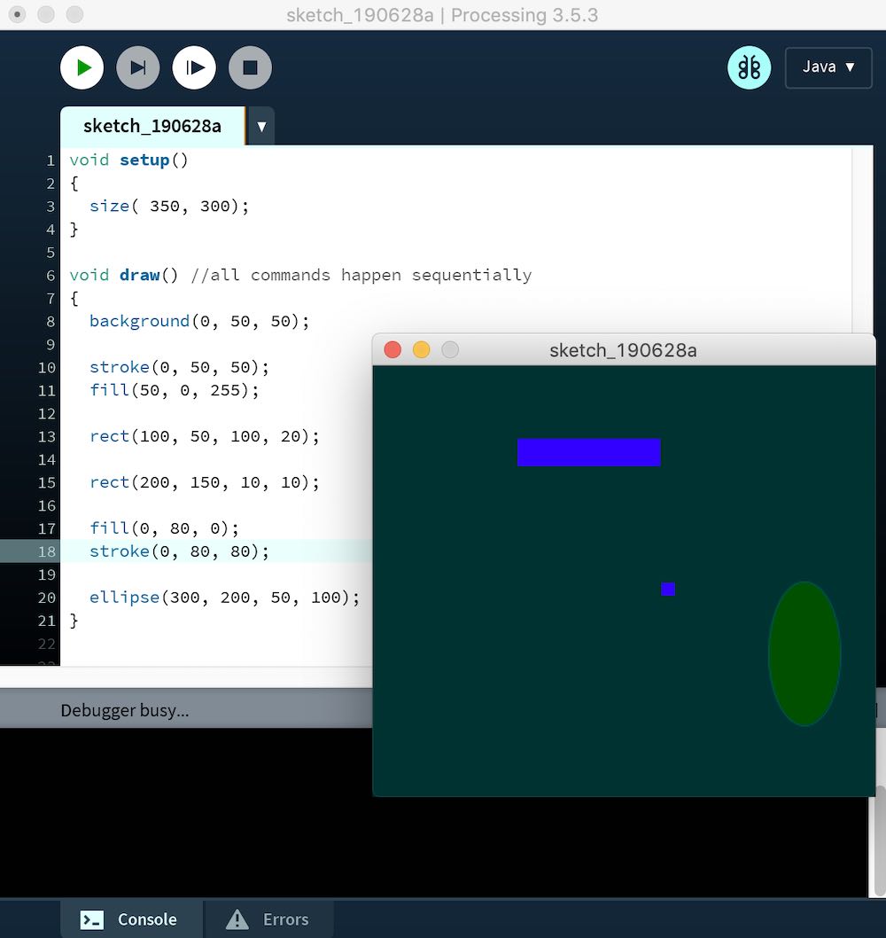
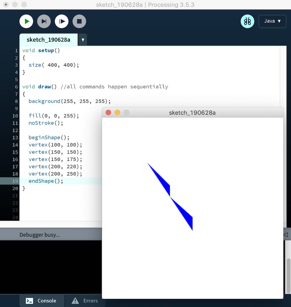
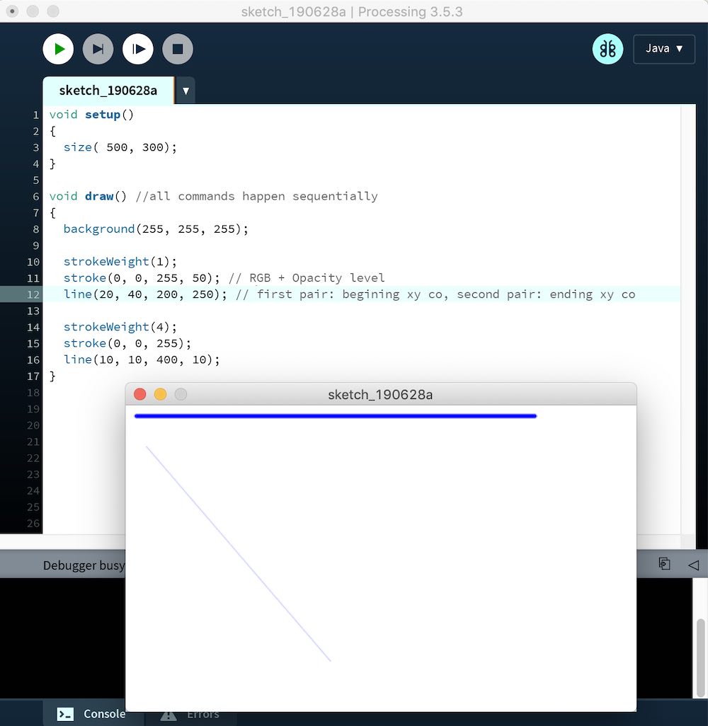
I tried to customize background, create shapes and lines with different commands:
Turning an LED ON/OFF via Processing
Then, I went through THIS tutorial with lighting up an LED on Arduino through an interface created on Processing.
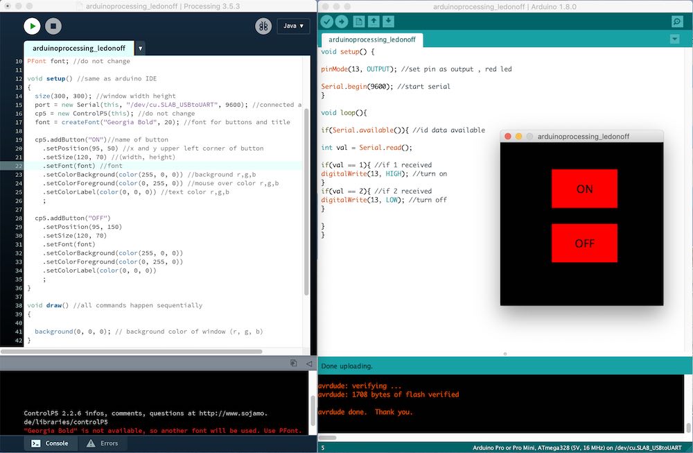
Here is the code for the interface:
//LED ON/OFF Interface with Processing
//Modified from Z-HUT
//by Siyu Chen
//June 28, 2019

import processing.serial.*; //for processing serial control
import controlP5.*; //for button control
Serial port; //do not change
ControlP5 cp5; //create controlP5 object
PFont font; //do not change

void setup() //same as arduino IDE
{
  size(300, 300); //window width height
  port = new Serial(this, "/dev/cu.SLAB_USBtoUART", 9600); //connected arduino port
  cp5 = new ControlP5(this); //do not change
  font = createFont("Georgia Bold", 20); //font for buttons and title

  cp5.addButton("ON")//name of button
    .setPosition(95, 50) //x and y upper left corner of button
    .setSize(120, 70) //(width, height)
    .setFont(font) //font
    .setColorBackground(color(255, 0, 0)) //background r,g,b
    .setColorForeground(color(0, 255, 0)) //mouse over color r,g,b
    .setColorLabel(color(0, 0, 0)) //text color r,g,b
    ;

  cp5.addButton("OFF")
    .setPosition(95, 150)
    .setSize(120, 70)
    .setFont(font)
    .setColorBackground(color(255, 0, 0))
    .setColorForeground(color(0, 255, 0))
    .setColorLabel(color(0, 0, 0))
    ;
}

void draw() //all commands happen sequentially
{

  background(0, 0, 0); // background color of window (r, g, b)

}

void ON() {
  port.write(1);
}

void OFF() {
  port.write(2);
}
CP5 is a user interface library that this code uses. As you see, the On and Off rectangles are recognized as buttons.
This part of the code synchronizes with the Arduino if command:
void ON() {
  port.write(1);
}

void OFF() {
  port.write(2);
}
Arduino code with the if command:
void setup() {

pinMode(13, OUTPUT); //set pin as output , red led

Serial.begin(9600); //start serial
}

void loop(){

if(Serial.available()){ //id data available

int val = Serial.read();

if(val == 1){ //if 1 received
digitalWrite(13, HIGH); //turn on
}
if(val == 2){ //if 2 received
digitalWrite(13, LOW); //turn off
}

}
}
Here is the result: