Week 10: Input Device
During the embedded programming week, we programmed our hello world with a code for the LED light and the button. However, we were very limited in what we could do on the hello world board with a 14 legs attiny 44, especially if we want to work with various sensors. The hello world board still requires an ISP even after burn bootloader. It also has limited pin headers for connecting sensor boards.
Arduino Board
The goal of this week is to design a microcontroller board, add a sensor to it and read it. The board would need to be able to read sensor inputs, and eventually turning inputs into outputs. For example, reading a person in motion as input and outputing LED on; reading a person still as input and outputting LED off. An Arduino board is an existing board that would allow one to upload program onto its microcontroller, and reads digital or analog input and output. Here is the anatomy of a Arduino UNO board:
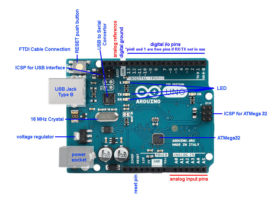
Major Components:
USB
•powers and loads program onto the board
Two ICSP
Voltage Regulator
•controls the amount of voltage that is let into the board
•turns away extra voltage that harms the circuit
•has to work with two capacitors
22pF capacitors
•works with VR
•coupling capacitors that regulates spikes
•makes voltage clean
16MHz Crystal
Female pins
•Digital I/O, Analog, Power (including RESET), AREF, GND
RESET button
Power LED
RX TX LED
Breadboard Arduino
In class, we made a breadboard Arduino as a mock up (tutorial we followed).
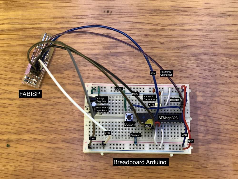
Although I find the breadboard a way to sketch a working circuit before working on an eagle file, I find this method really messy with the wires (I can understand why Neil hates breadboard lol). Also, if you mess up the VCC and GND connection on the breadboard, you can overheat the microcontroller and break it. I am really excited about making my own Arduino by this point*A*! P.S. MY LOVE HATE RELATIONSHIP WITH ELECTRONICS OFFICIALLY BEGINS HERE.
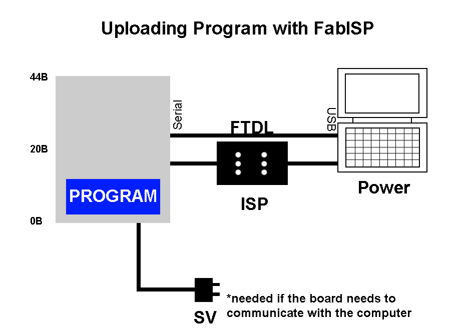
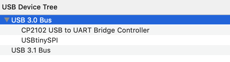
After I made the connection between my breadboard and FabISP, I attached it onto my computer and upload a simple blink code to test the LED light.
/*
  Blink
  Turns on an LED on for one second, then off for one second, repeatedly.

  Most Arduinos have an on-board LED you can control. On the UNO, MEGA and ZERO
  it is attached to digital pin 13, on MKR1000 on pin 6. LED_BUILTIN is set to
  the correct LED pin independent of which board is used.
  If you want to know what pin the on-board LED is connected to on your Arduino model, check
  the Technical Specs of your board  at https://www.arduino.cc/en/Main/Products

  This example code is in the public domain.

  modified 8 May 2014
  by Scott Fitzgerald

  modified 2 Sep 2016
  by Arturo Guadalupi

  modified 8 Sep 2016
  by Colby Newman
*/


// the setup function runs once when you press reset or power the board
void setup() {
  // initialize digital pin LED_BUILTIN as an output.
  pinMode(LED_BUILTIN, OUTPUT);
}

// the loop function runs over and over again forever
void loop() {
  digitalWrite(LED_BUILTIN, HIGH);   // turn the LED on (HIGH is the voltage level)
  delay(1000);                       // wait for a second
  digitalWrite(LED_BUILTIN, LOW);    // turn the LED off by making the voltage LOW
  delay(1000);                       // wait for a second
}
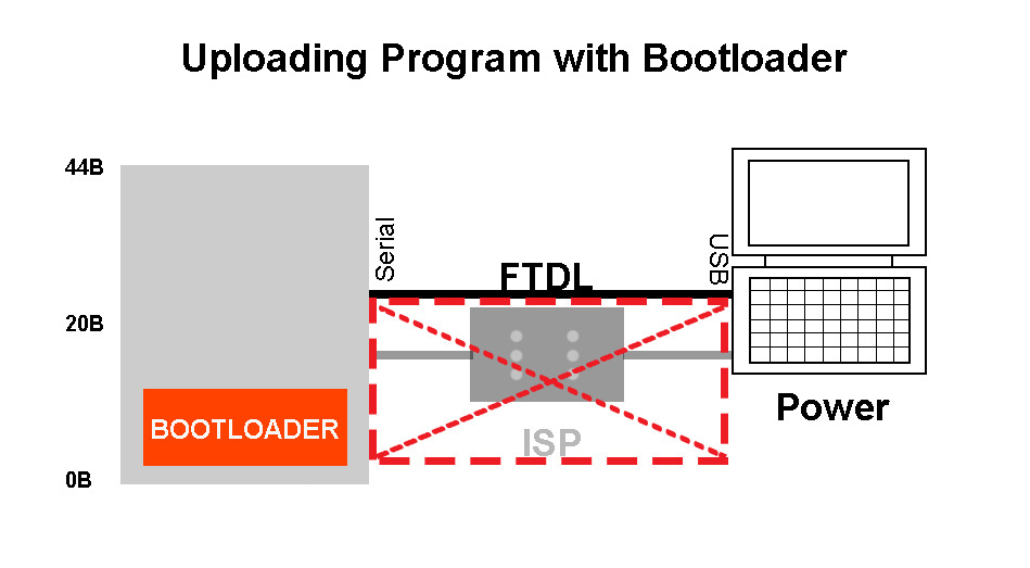
Also, in order to upload program onto my microcontroller without a FabISP in the future, I burnt the bootloader onto the AtMega328.
Test with motion sensor
I am really excited about this week, since learning how to sync sensor with LED light is one of my reasons for attending Fab Academy. In class this week, I used the HC-SR501 PIR Motion Sensor that we have at Fab Lab O to sync motion input with LED light output.
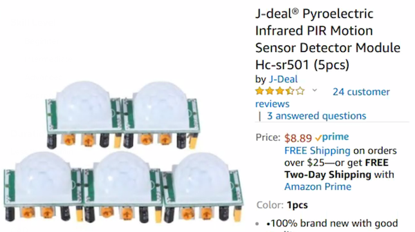
Here is the layout of the board on this motion sensor:
The motion sensor is controlled by one Sensitivity screw and one Time delay screw. According to THIS summary, “for the sensitivity goes: Clockwise=>High sensitivity CCW=> low sensitivity (3-7 m). for the Output timing it is CW=>long, CCW=> short (3-300 sec)”.
“The right prong of the connector is for Vcc (+5-20V), the middle one is signal out and the left one is ground. The output is either high (3.3V) or low (0v)”.
There is also a Jumper on the board: “If it is in its top position (H) it is in auto reset mode. If set to Auto-reset the sensor will stay high until the motion stops. After motion is no longer detected the output will go low. If set to No reset (L) the sensor will stop sensing once it has triggered, and stays high for the preset time period."
Here is the example code I have used:
                    /*
 * //////////////////////////////////////////////////
 * //making sense of the Parallax PIR sensor's output
 * //////////////////////////////////////////////////
 *
 * Switches a LED according to the state of the sensors output pin.
 * Determines the beginning and end of continuous motion sequences.
 *
 * @author: Kristian Gohlke / krigoo (_) gmail (_) com / https://krx.at
 * @date:   3. September 2006
 *
 * kr1 (cleft) 2006
 * released under a creative commons "Attribution-NonCommercial-ShareAlike 2.0" license
 * https://creativecommons.org/licenses/by-nc-sa/2.0/de/
 *
 *
 * The Parallax PIR Sensor is an easy to use digital infrared motion sensor module.
 * (https://www.parallax.com/detail.asp?product_id=555-28027)
 *
 * The sensor's output pin goes to HIGH if motion is present.
 * However, even if motion is present it goes to LOW from time to time,
 * which might give the impression no motion is present.
 * This program deals with this issue by ignoring LOW-phases shorter than a given time,
 * assuming continuous motion is present during these phases.
 *
 */

/////////////////////////////
//VARS
//the time we give the sensor to calibrate (10-60 secs according to the datasheet)
int calibrationTime = 10;

//the time when the sensor outputs a low impulse
long unsigned int lowIn;

//the amount of milliseconds the sensor has to be low
//before we assume all motion has stopped
long unsigned int pause = 1000;

boolean lockLow = true;
boolean takeLowTime;

int pirPin = 2;    //the digital pin connected to the PIR sensor's output
int ledPin = 13;


/////////////////////////////
//SETUP
void setup(){
  Serial.begin(9600);
  pinMode(pirPin, INPUT);
  pinMode(ledPin, OUTPUT);
  digitalWrite(pirPin, LOW);

  //give the sensor some time to calibrate
  Serial.print("calibrating sensor ");
    for(int i = 0; i < calibrationTime; i++){
      Serial.print(".");
      delay(50);
      }
    Serial.println(" done");
    Serial.println("SENSOR ACTIVE");
    delay(50);
  }

////////////////////////////
//LOOP
void loop(){

     if(digitalRead(pirPin) == HIGH){
       digitalWrite(ledPin, HIGH);   //the led visualizes the sensors output pin state
       if(lockLow){
         //makes sure we wait for a transition to LOW before any further output is made:
         lockLow = false;
         Serial.println("---");
         Serial.print("motion detected at ");
         Serial.print(millis()/1000);
         Serial.println(" sec");
         delay(50);
         }
         takeLowTime = true;
       }

     if(digitalRead(pirPin) == LOW){
       digitalWrite(ledPin, LOW);  //the led visualizes the sensors output pin state

           }
       }
However, I was still unable to figure out the best Sensitivity and Time adjustment at this point. Later, I figured out that it might be because the board did not have enough power for the motion sensor to response fast enough (please see section below for the motion sensor working with the board I made this week).
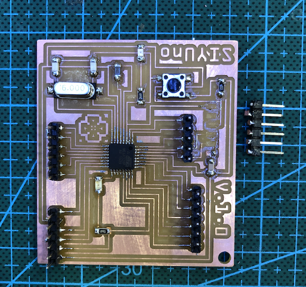
Make SIYUno
SIYUno, named after my name (Siyu) and number one in Italian (Uno) just like the Arduino Uno board, is the board I am making in replacing an Arduino board. At first I was extremely overwhelmed by designing my own schematics for the board. I looked at an Arduino Uno schematic and the schematic of satkshakit (a board designed by a Fab Academy student few years ago during the Input Device week, which was reused by many student in the past) to understand the connections between the microcontroller and the components.
The Board
The schematic of satkshakit was helpful, but I decided to include also separate FTDI and ISP connection pinheaders. This is the initial schematic of SIYUno:
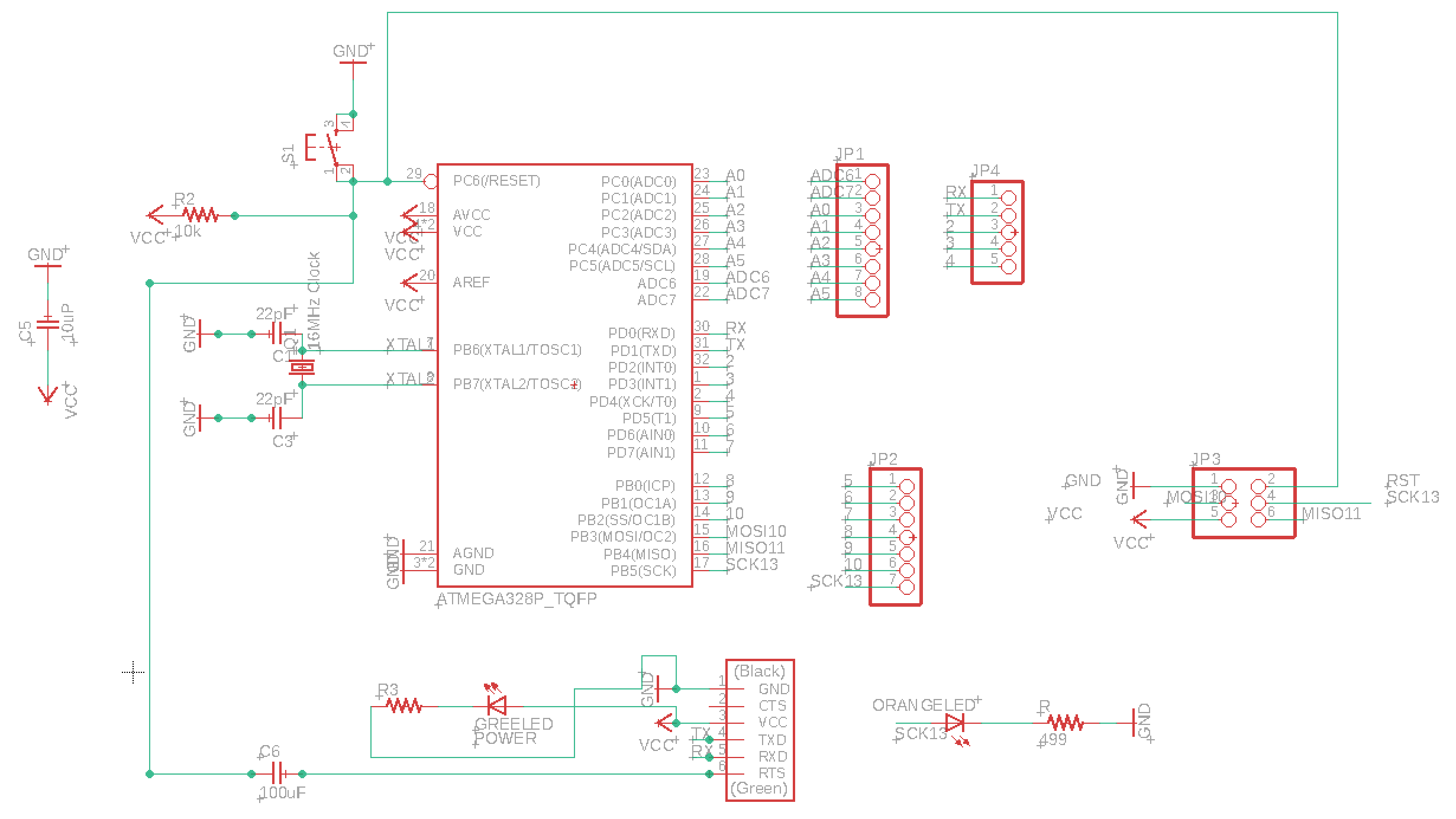
Once I began to work on the board wires, I found it difficult to connect the 2x3 ISP port with the microcontroller. One of MISO/MOSI/SCK was always in the way. I decided to use a 1x6 pinhead. Here is the modified schematic:
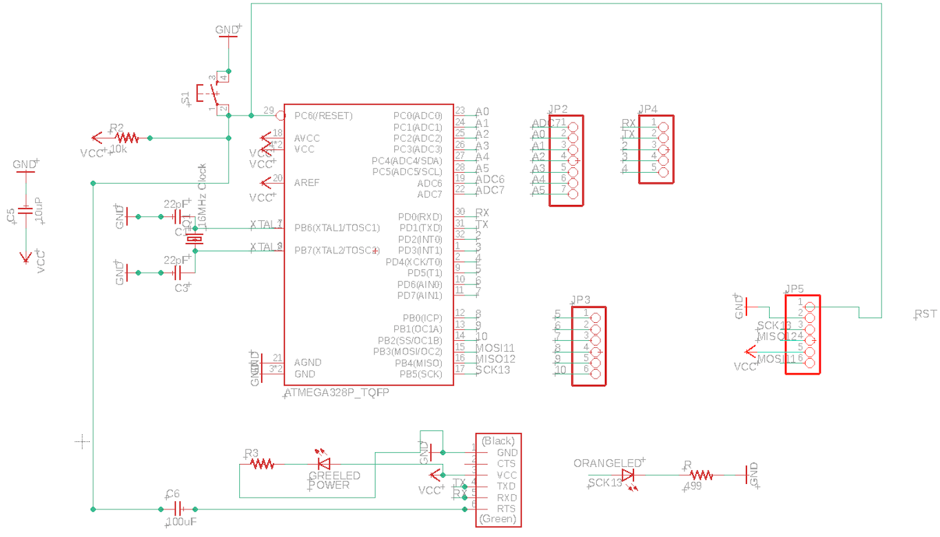
Note: later during the regional meeting, Rodrigo (Instructor at Fab Lab Seoul) recommended me to solder jumper wires to resolve connections that are impossible to make without touch the other wires, I will look further into that for my future designs.
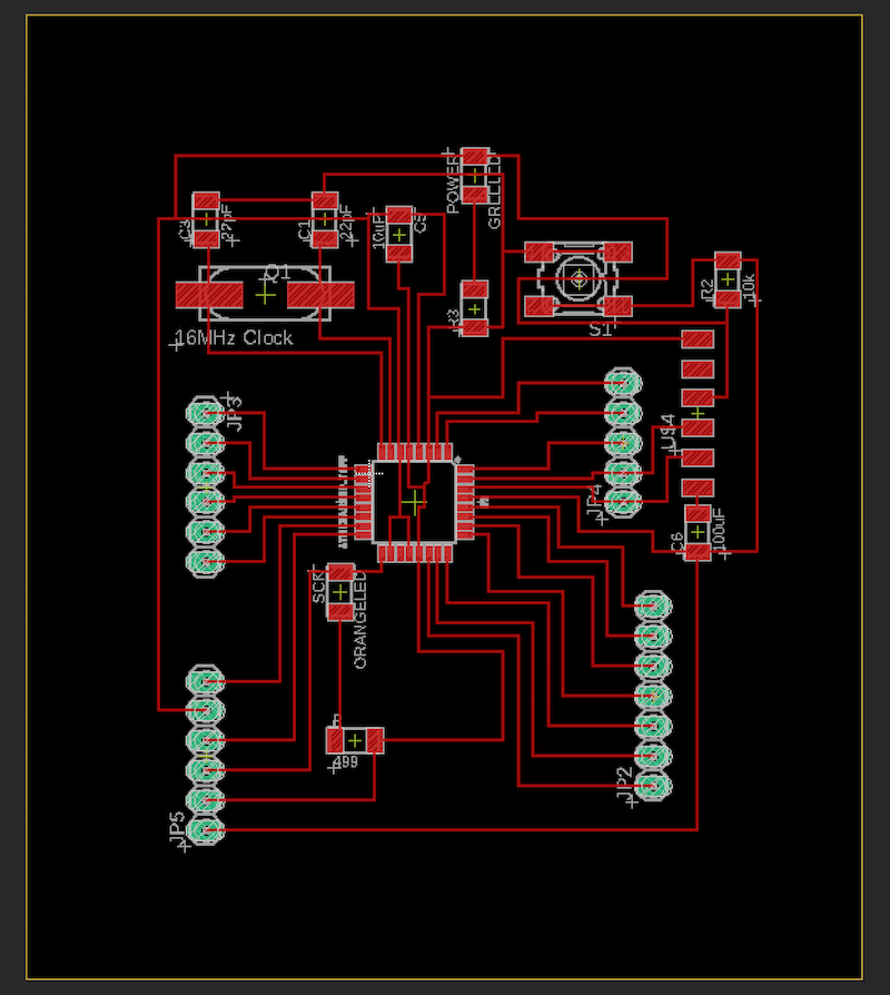
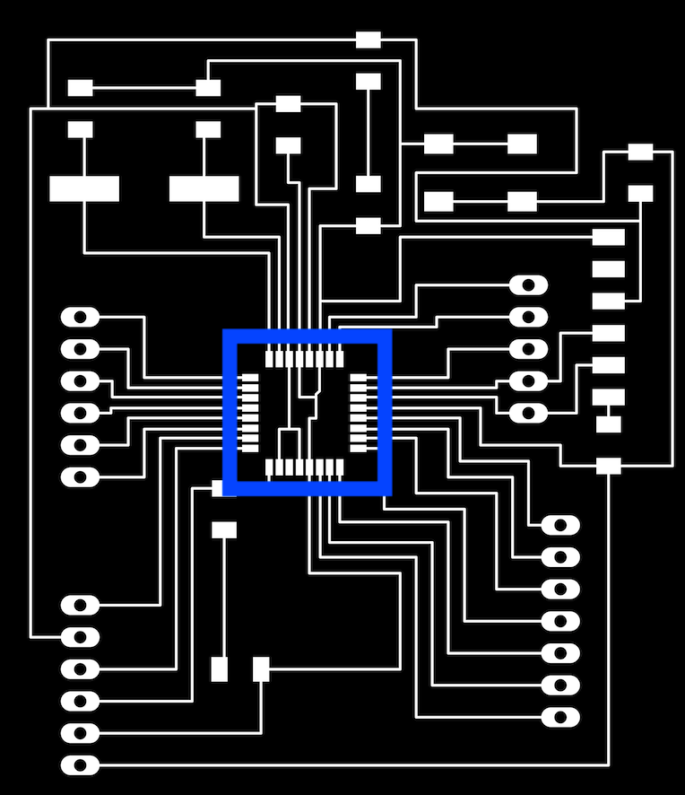
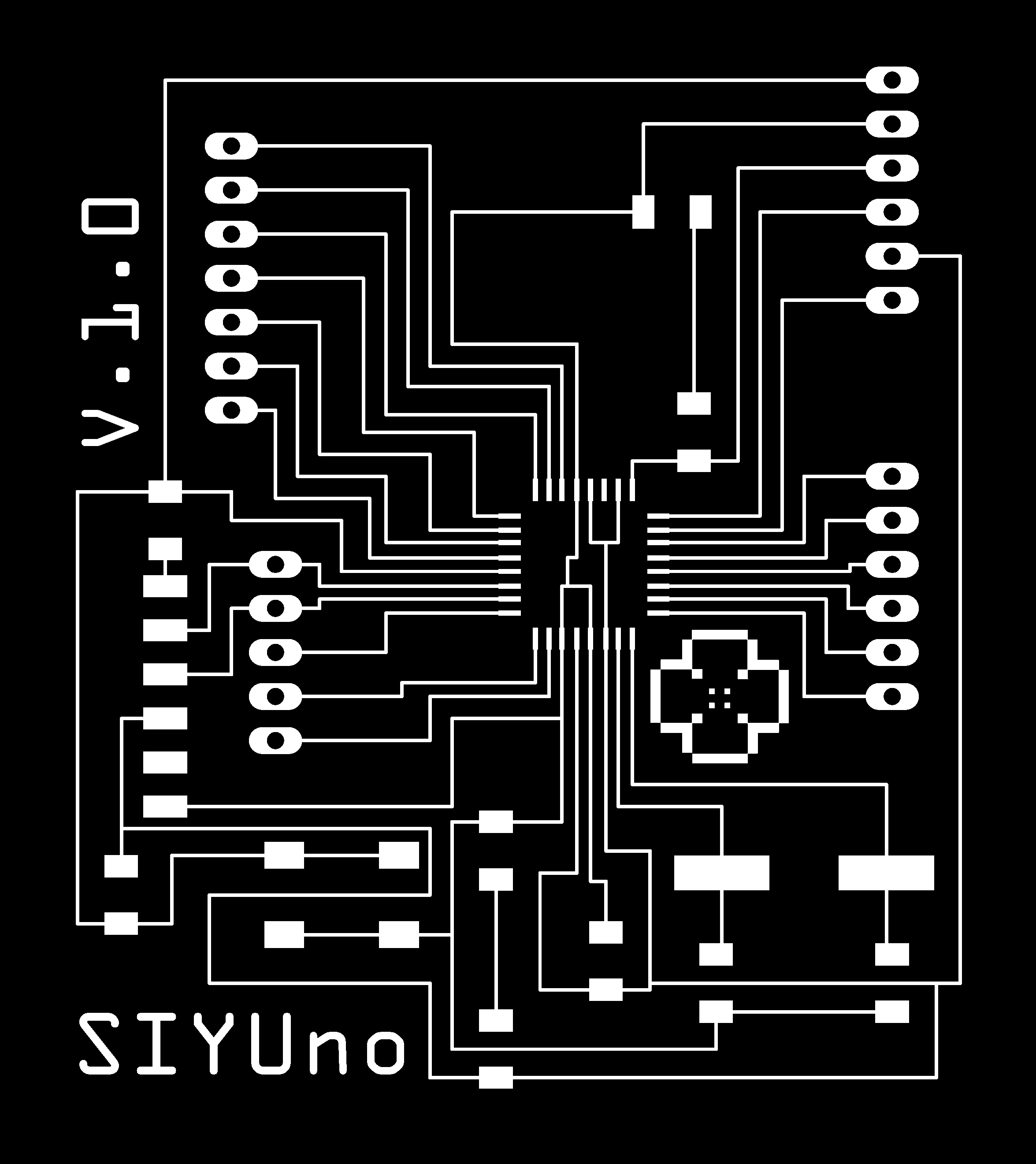
From this schematic, I finalized my board design:
My classmate Pamela suggested to measure the gap between the atMega legs on Photoshop. On her first pcb board, the gap was 0.2mm, which was impossible for the 0.4mm endmill to cut. After checking on Photoshop, I realized I had the same issue as Pamela. So I manually modified the gap:
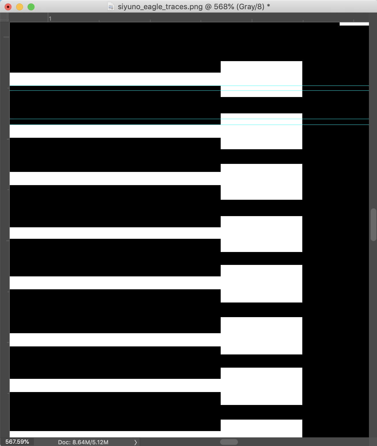
Note: during the regional meeting, Rico (student at Fab Lab Kamakura) suggested me to change the dimension of the microcontroller in Eagle. Here is the process:
1. Select the microcontroller legs and click on Change/SMD/..
2. Put in the size for the leg in mil
3. Then right click on the selected leg in the board window and right click Change:Group
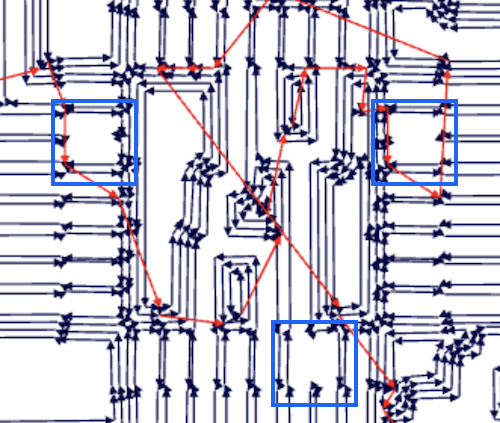
When I imported the image to fabmodule, I still had the gap issue. In the blue boxes you can see some of the legs are merging into the neighboring legs:
Then I went back into Photoshop and made further modifications. Here is the final bitmap images I have used for making my trace and outline path in fab module:
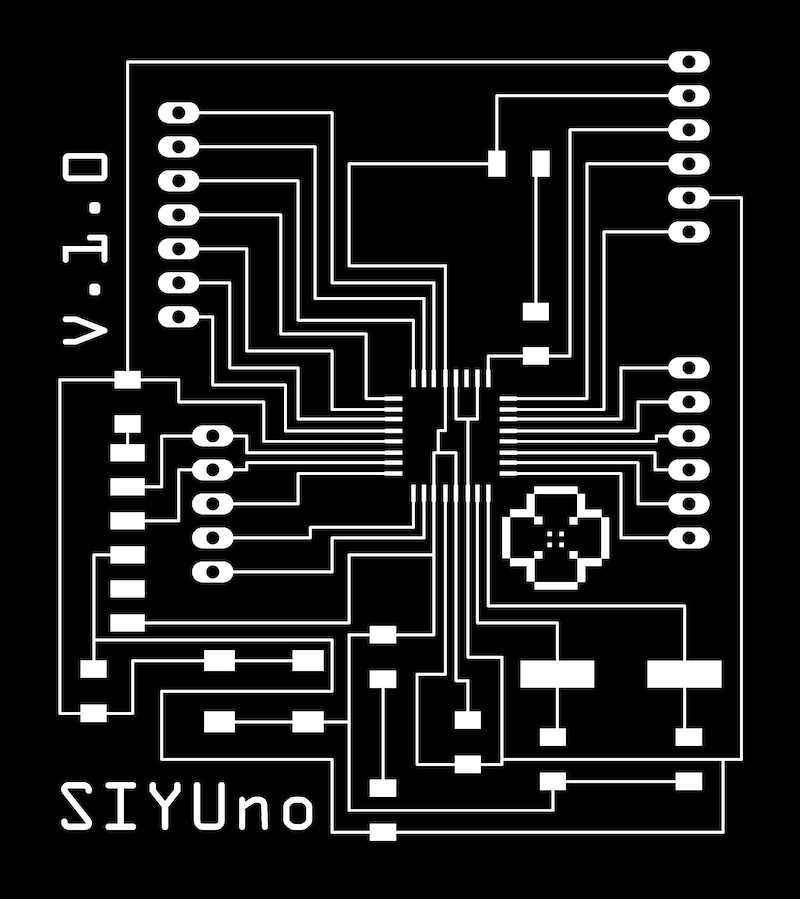
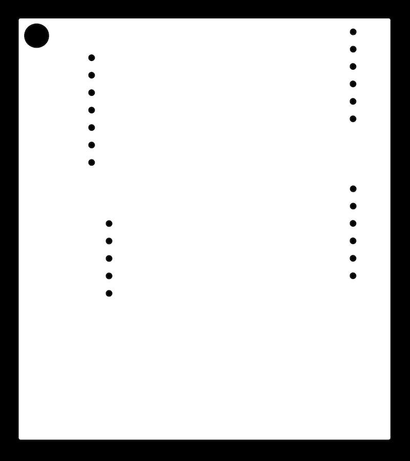
Note: since I am using through-hole components this week, I included the holes that need to be drilled in the outline. The big hole on the top left is there, because I want to make SIYUno into a necklace :D!
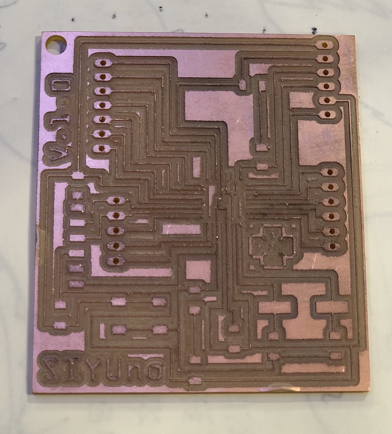
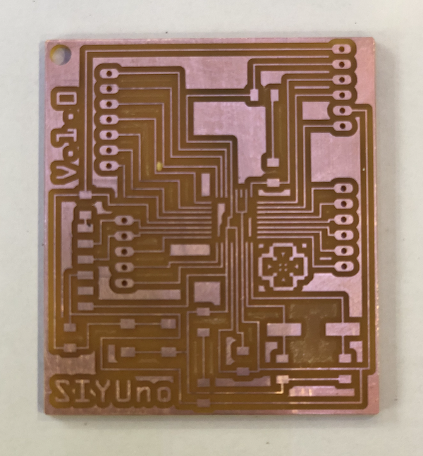
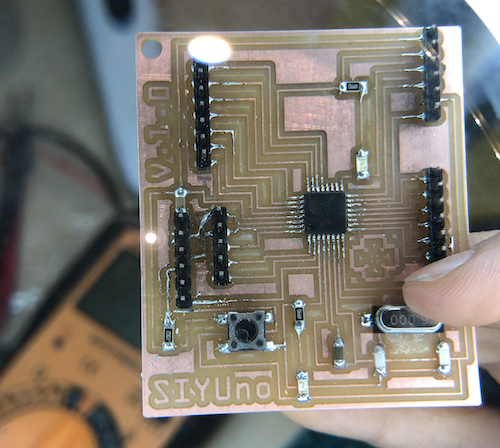
Then I made my path files in fabmodule and output them onto the Roland milling machine (see week 04 for further information on fabmodule and the milling machine). This first board did not came out well since the endmill was really worn out. Many wires connecting to the atmega were gone :……….( Then I found a perfect 0.4mm endmill with a bigger shank diameter and changed the collar on the milling machine (THANKS TO THE CNC WEEK, I LEARNT HOW TO CHANGE THE COLLAR!) This time the pcb board came out beautifully!!!
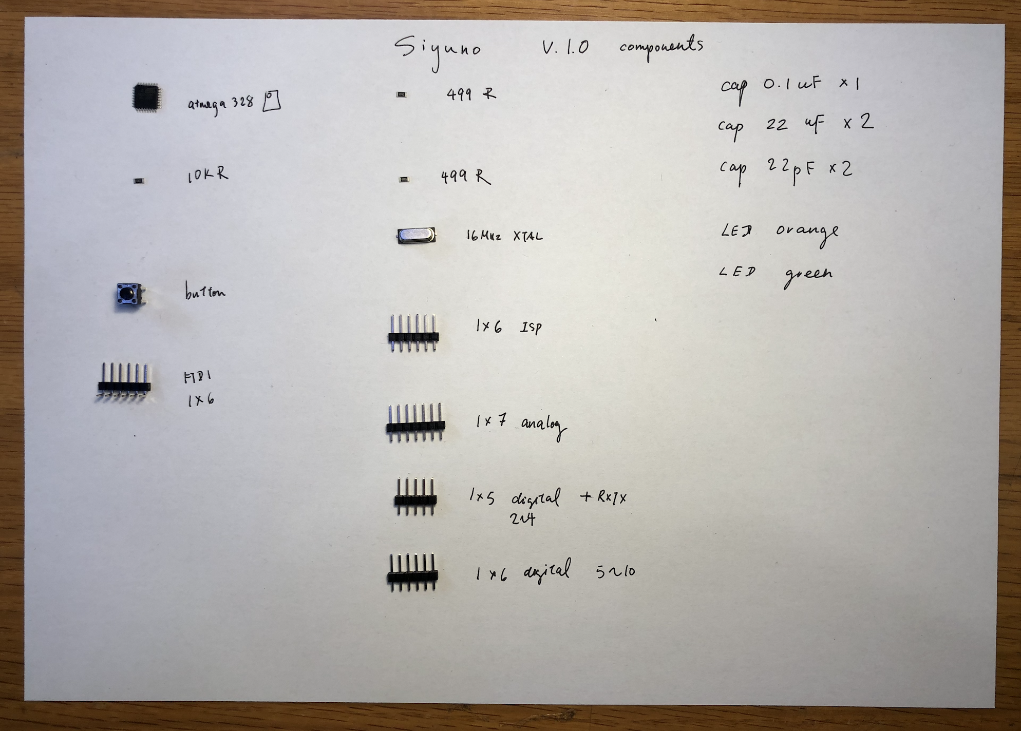
To make soldering process easier, I mapped out all the components on my board based on my eagle file. I also made a list of all the components I need for soldering. NOTE: the direction of the actual PCB board is flipped.

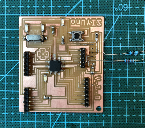
After making seven failed board few weeks ago, my soldering skill improved significantly! Soldering also went smoothly :D
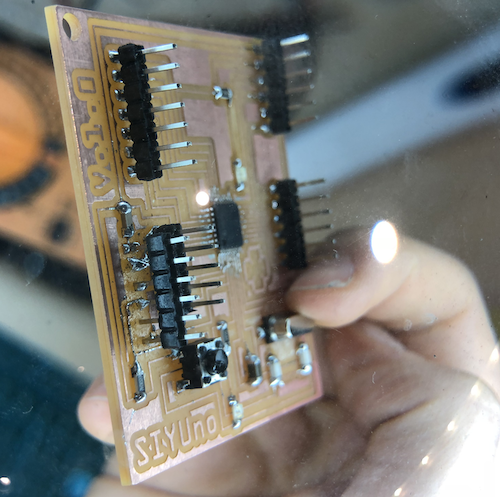
Everything sounded too perfect at this stage. Then, when I tried to straighten the FTDI 1x6 pins with a tweezer, I ripped off the FTDI pins off the board together with the copper underneath……
ACCIDENT! BROKEN COPPER
Saverio suggested me to fix the connections by cutting off wires from a capacitor in replacement of the copper and then add solder. Also, he suggested me to drill holes onto the board and put a 1x6 through-hole male pin headers for the pin headers to sit in still while soldering.
Before fixing the FTDI connection, I first checked whether the board works with the FabISP. When I tried to upload a blick program onto the board, it failed at initialization. I was ABLE TO UPLOAD after cleaning excess solder of the atmega legs and adding more solder onto other components.
Then I started to fix the broken copper for my FTDI component :(
1. Add solder onto the edge of the missing wire. Then, add a piece of capacitor. Make sure the piece of capacitor expand a bit over the pin header holes since you would need to connect the wire with the component. You can always use a tweezer to wrap the extra capacitor wire around the pin header legs before soldering.
2. Solder. It sounds simple, but the solder falls off constantly from the thin capacitor legs, which causes it to move. Use a tweezer to hold the wire!
3. Once you finished fixing, check t he connections under a magnifier and with a multimeter.
Eventually, my computer could read my FTDI! YAH! However, I was unable to upload program without my ISP due to some underlying FTDI connection issue. Here is the error message I get:
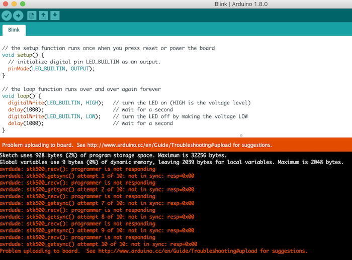
I will try to: 1. Use another RX/TX leg on my board to see whether if it’s the RX/TX leg not working (in the section below you can see my FTDI VCC and GNC connection works with a sensor); 2. Make a new board.
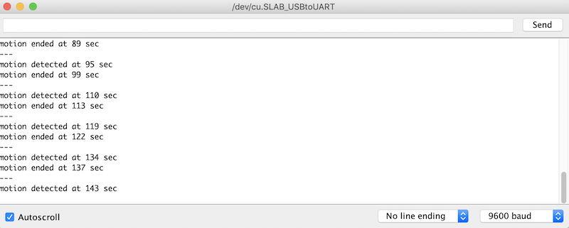
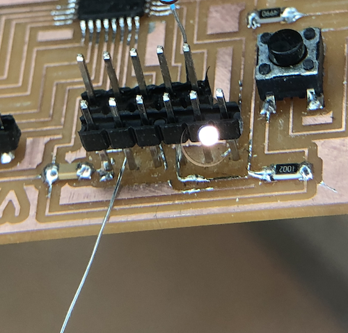
SIYUno IN ACTION!!!
I imported the same code onto the board. At first, the delay was too long. Then I adjusted the screws on the motion sensor board (left is sensitivity; right is time delay):
Here is the board in ACTION!!
Also, I have realized the motion sensor only works when my computer is connected to the charger. It seems the power of the FABISP on its only is not enough for the motion sensor to work.
Conclusion
The week has been filled with ups and downs. I have many things I wanted to try, but I spent way too long on making and fixing my board. I am happy to know I still have the output week to experiment with the sensors. For the coming week, I aim to make another board with my ftdi connections properly soldered, understand analog i/o, and try heart beat sensor and sound sensor, since one of them might be used in my final project.