_week 9
Embedded programming
Group assignment
For this week we have to compare the performance and development workflows for other architectures.
But what is the meaning of this? what is an architecture?
From my understanding, just as in architecture there is a process to design and planify the construction
of a building/site, in computer science there is also a planification, a set of rules, an organization,
an implementation, behind the computers systems.
I find the following definition easy to understand for a beginner and outsider to this new world of
electronics like me, to what a computer architecture means:
Computer architecture, like other architecture, is the art of determining the needs of the user of a
structure and then designing to meet those needs as effectively as possible within economic and
technological constraints.
--source from Wikipedia--
Harvard architecure and von Neumann architecture are very important. The first one based on the Harvard Mark I computer and the second one is based on the work of John von Neumann called First Draft of a Report on EDVAC that described the architecture of a digital computer.
For me, right now it's still a very complex terminology and description of how different computer
architectures works but I learned that many architectures have been developed throughout the years, many
and mainly based on the architectures mentioned above.
And these architectures are crucial to understanding how a system works but also it's limitations and/or
implications.
For example reading the data sheet of our ATtiny44 we can know the type of architecture it uses, here is the specs overview of the ATtiny44: (information extracted from the data sheet)
ATtiny24A/44A/84A are low-power CMOS 8-bit microcontrollers based on the AVR enhanced RISC architecture. By executing powerful instructions in a single clock cycle, the ATtiny24A/44A/84A achieves throughputs approaching 1 MIPS per MHz allowing the system designer to optimize power consumption versus processing speed.
RISC architecture means Reduced Instruction Set Computer and it is another type of architecture that is the succesor of the CISC architecture (Complex Instruction Set Computers)
There are several differences among these two architectures, noting down here two of the main ones:
1_CISC includes multi-clock for complex instructions, vs RISC that uses a single-clock for reduced
instructions
2_CISC has transistors used for storing complex instructions, vs RISC that has more transistors for
storing the memory
For a deeper understanding between this two architectures, check out this links where i took the
information from:
1_What is RISC and CISC Architecture with Advantages and
Disadvantages
2_RISC vs CISC
3_What is RISC and CISC, Their
Architecture and the Difference Between Them
To know more about the group assignmet about the documentation on the different types of architectures, chec out my classmate Flavie website.
Individual assignment
For this week's assignment we have to read the data sheet of the ATtiny44 and program our board to do something using different programming languages and environments.
_ABOUT THE DATA SHEET
The data sheet of the ATtiny44 is a complete manual about the whole world behind this tiny but huge
universe.
It is a complex manual with many definitions and concepts that are hard to understand if you are giving
your first steps in the world of electronics, just like me.
I was a bit lost reading throughout some pages, but I came to the conclusion that this assignment of
reading the data sheet was very useful to me to learn how to read the manual to find the information we
need to use.
When using our MCU we will have to refer to the data sheet back and forth most of the time, so it's
important to give it a read to at least know the structure of the data sheet and quickly find what you
are looking for.
At the stage we are of the course and for the assignments we've been doing, it's important to understand and know the pins of the ATtiny44 and their meaning.
Some new things I learnt reading the data sheet are:
1_The ATtiny44 is based on the AVR enhanced RISC architecture, which is based on the Harvard
architecture.
2_It is an 8 bit microcontroller, meaning it is capable ot transfer eight bits of data at the same
time.
3_It has twelve programmable I/O Lines (input/output)
4_The ports B (PB0-PB3) are 4-bit bi-directional I/O port with internal pull-up resistors.
5_The ports A (PA0-PA7)are 8-bit bi-directional I/O port with internal pull-up resistors.
6_***The ports that say ADC mean stands for Analog-to-Digital Converter, this means these ports
can be used to convert the digital signal into analog.
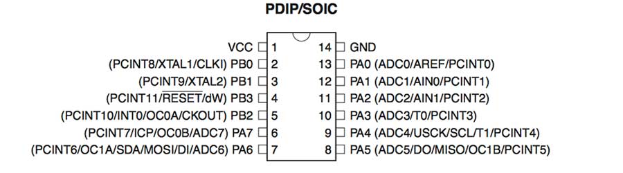
Throughout this assignment you will need to check the pinout map to see the ports where you connected your LED and button.
_WHAT IS A PROGRAMMING LANGUAGE & A PROGRAMMING ENVIRONMENT?
"hello, world"
A programming language is the communication language used in computer programming.
It is basically a series of instructions that tell a computer what to do.
There are many programming languages, some of them are: ALGOL, APPLESCRIPT, C (one of the most importants, operative systems like Windows, MacOS, iOS, Android, browsers and 3D games engines are written in C language), C++, JAVA, JAVASCRIPT, PYTHON, RUBY...
I found this useful site with information about programming languages, I know now where HELLO
WORLD comes from =P:
_SAY ‘HELLO WORLD’ IN 28 DIFFERENT
PROGRAMMING LANGUAGES
A programming environment is the environment where this language is hosted, tested and ran on.
Here is where Integrated Development Environments enter, the IDE are software applications where
you write the code to program your system/software.
They were designed to improve the developer productivity using an interface that allows them to
configurate/modify the codes with multiple development tools, among other features. (source: veracode).
The IDEs normally run under a specific language, but there are IDEs that can manage multiple languages.
Some examples of IDEs are:
_XCODE, that supports C, C++, Objective-C, Objective-C++C, Java, AppleScript, Pythin, Ruby,
ResEdit and Swift.
_Eclipse supports C, C++, Python, Perl, PHP, Java, Ruby and more
_Komodo supports Perl, Python, Tcl, PHP, Ruby, Javascript and more
_NetBeans supports Java, JavaScript, PHP, Python, Ruby, C, C++ and more
_PROGRAMMING MY BOARD
My current MCU has one button and one LED, and the idea is to program it in different languages and
environments to do something.
I plan to program different options when pressing the button and turning on and off the LED.
But before doing that, it is important to know in which pins of my MCU I have my LED, button.
Below is a diagram of my MCU and the components I will be using highlighted:
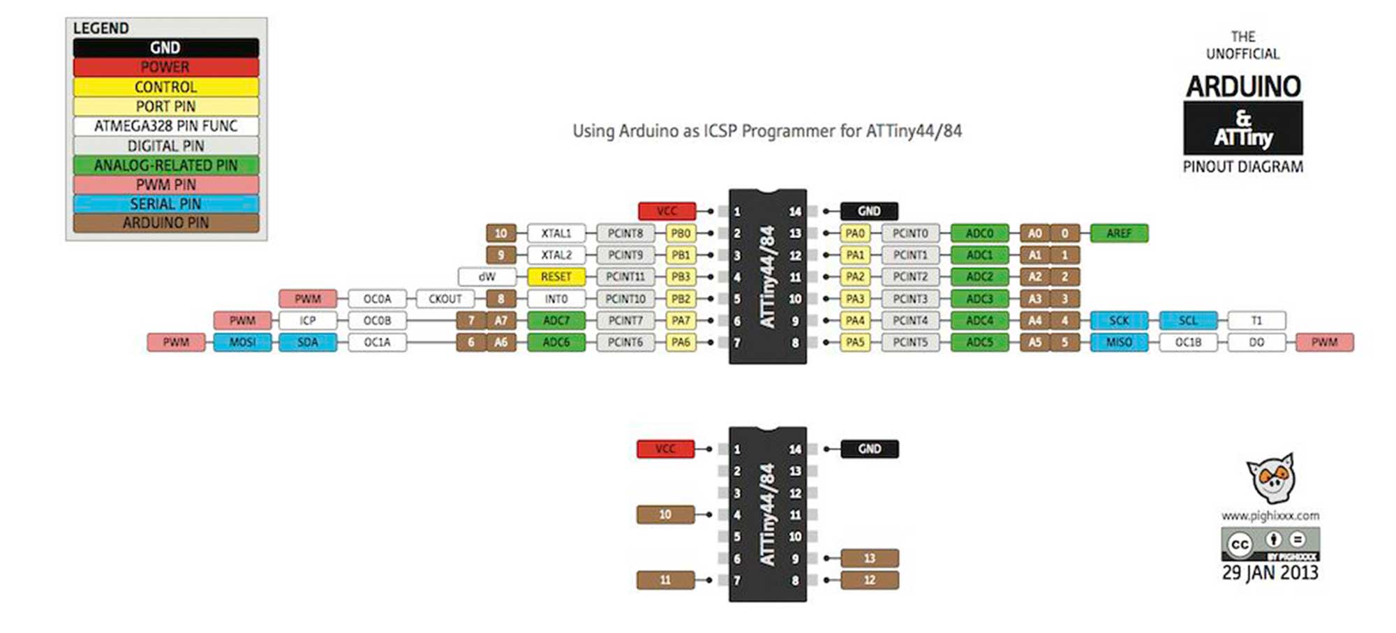
_ARDUINO PROGRAMMING
As I will start using ARDUINO IDE for the programming so it is useful to have the pins convertions table from ATtiny44 to ARDUINO pins.
For example my LED in the ATtiny is on pin number 6, and when using ARDUINO IDE the number of the pin is not the same as the one used for ARDUINO convention, so in this case pin6 in ARDUINO is pin 7(A7).
Two weeks ago I did my first programming to my MCU, and it was running the
hello.ftdi.44.echo.c file
and using the serial monitor from ARDUINO IDE I was able to display "hello, world".
You can find HERE
the documentation.
_ARDUINO BLINK PROGRAMMING
Inside ARDUINO IDE you can find a library of basic codes to program your board.
The next test I will do is the BLINK code.
First thing you need to know is that you need a programmer to load a program into your
microcontroller.
In our case, unless you have done the BURN BOOTLOADER on ARDUINO IDE, you will need an IN
SYSTEM PROGRAMMER, which in this case is our FABISP.
BOOTLADER what basically does is to write on your microcontroller memory what the FABISP
internally has written for the serial communication. This way you can write and overwrite new programs
without the need of using an ISP.
But note that the very first time you load a code you do need an ISP to program it.
The only draw back is that BOOTLOADER uses a lot of memory (as you are loading information into your memory), leaving less space to other tasks.
Ok, so for now I will be using my FABISP to load the programs, so first thing you need to do is to
connect your new MCU to your FABISP using the ISP cable, and on the FTDI pins connect your FTDI
cable, which now will serve to give power to your MCU, so you can connect it to your computer or other
USB port to get the 5V you need.
When connecting them always check inside DEVICE MANAGER (for Windows users) that your FABISP is
recognized.
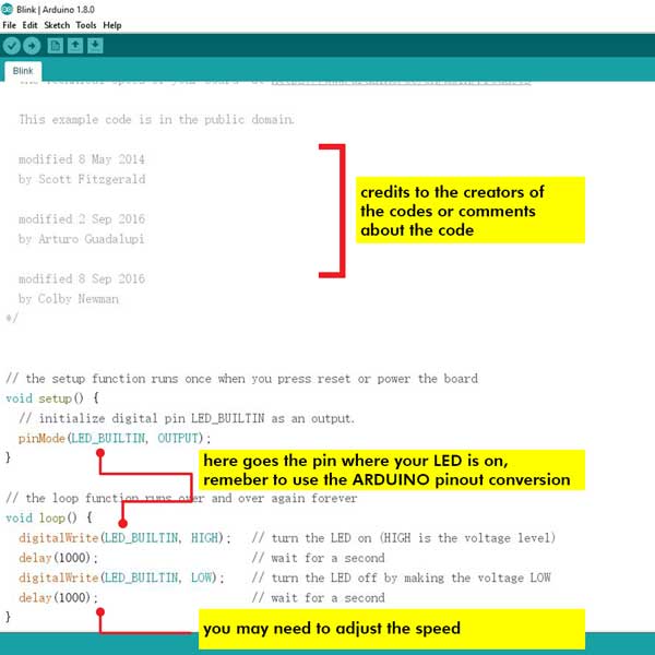
Open up ARDUINO and go to FILES > Examples > BASICS > Blink
This will open up a new window, they are called SKETCHES, as we are using a template, it already
has the code to make the LED blink (no button involved).
As you are programming your own attiny you need to change a few lines on the code and replace them with
your LED pin information:
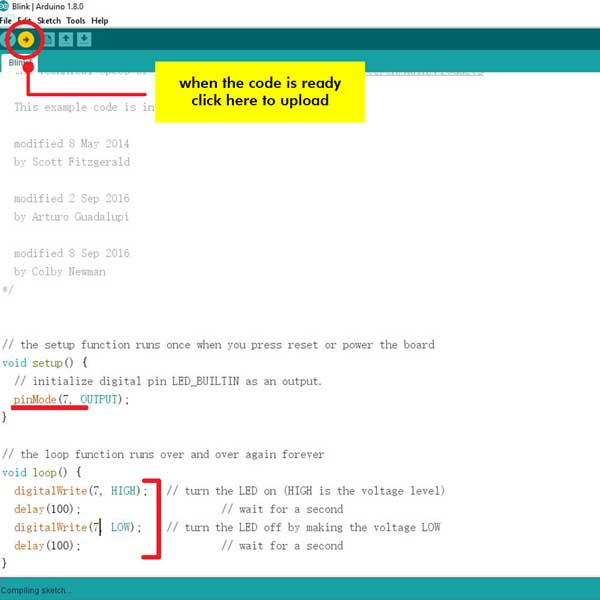
Remember to check inside TOOLS that you are using BOARD: ATtiny24/44/84, PROCESSOR: ATtiny44, CLOCK: External 20MHz, PROGRAMMER: USBtinyISP.
Now my MCU is blinking in aeternum until I unplug the current from it or I overwrite the code.
_ARDUINO SWITCH ON/OFF
Now I will run a code to use the switch button on my board.
This code when pressing it will turn on the LED, and when pressing once more will turn it off.
In ARDUINO website you can find lots of resources and codes templates.
For this exercise I used a template available in arduino website, written by
David A. Mellis.
This is the code structure and the modifications made:
/* switch
*
* Each time the input pin goes from LOW to HIGH (e.g. because of a push-button
* press), the output pin is toggled from LOW to HIGH or HIGH to LOW. There's
* a minimum delay between toggles to debounce the circuit (i.e. to ignore
* noise).
*
* David A. Mellis
* 21 November 2006
*/
int inPin = 3; // the number of the input pin
int outPin = 7; // the number of the output pin
int state = LOW; // the current state of the output pin
int reading; // the current reading from the input pin
int previous = HIGH; // the previous reading from the input pin
// the follow variables are long's because the time, measured in miliseconds,
// will quickly become a bigger number than can be stored in an int.
long time = 0; // the last time the output pin was toggled
long debounce = 20; // the debounce time, increase if the output flickers
void setup()
{
pinMode(inPin, INPUT);
pinMode(outPin, OUTPUT);
}
void loop()
{
reading = digitalRead(inPin);
// if the input just went from LOW and HIGH and we've waited long enough
// to ignore any noise on the circuit, toggle the output pin and remember
// the time
if (reading == HIGH && previous == LOW && millis() - time > debounce) {
if (state == HIGH)
state = LOW;
else
state = HIGH;
time = millis();
}
digitalWrite(outPin, state);
previous = reading;
}
NOTE:
1_Remember that when we did our board the resistor we used on our button is a pull down resistor, so
when using this code, remember to change the in state= LOW.
2_We changed the debounce time to 20, because the original MAKE file we fused into our board
doesn't have specified the option Divide clock by 8 internally; [CKDIV8=0], so the time
used between arduino platform and our board is not the same, so we have to reduce the debounce to at
least 8 times less, otherwise if we leave 200 as the original code, the time between pressing the button
and lighting the LED would be very long.
_ARDUINO CLICK ON ME! & SERIAL MONITOR
I wanted to play a bit more with Arduino and I started to search some more codes.
I found on a previous student website a code she did where every time she pressed the button she would
get the word "button" on her serial monitor.
I checked her code of Dorota Orlof that is based on the code originally made by Tom Igoe, and I decided to use it making some modifications.
The first modification I did was to change the mySerial.begin(9600), as the speed was too low.
I then decided to add another function, every time you press the button you would see the LED on and also the word displayed would be click me!.
So the first code I did was using Dorota's one but adding the variables from the SWITCH
ON/OFF code, so that the LED would turn on every time I pressed it.
I thought it would be as easy as copying and pasting both codes, but is not that simple...
The code has to be integrated, the way I was using it, it did work but it was not the correct way of
doing it.
Assisted by my instructor Saverio, we had a look into the code and analyzed it together.
We did several modifications on the code and added comments to better understand the meaning of some
variables.
The code still in progress, it doesn't work perfectly as the first time you press the button the LED
lights too fast and a bit too long, but it then works fine every time you click.
I tried changing the debounce time to see if that could help, but still doesn't work very well. I need
to figure out the right way to fix the code.
NOTE It was tricky to understand this code at first, so I had to re-read the code several times and check on Arduino website the meaning of most of the variables used.
You can find the arduino code below on DOWNLOAD FILES
_PROGRAMMING WITH C
I am attempting to use C language to run a simple task on my MCU, the task is to turn on the LED, I want to start simple task and then see if it works out.
First thing is to understand a bit more about C language and what environment to use.
After my regional review last Tuesday, one of my classmates shared a link to a video tutorial about
programming AVR microcontrollers in C.
I decided to check it out, and it was super super useful, although is a bit long and seems tedious at
first, I would strongly recommend watching this video before you even start this assignment.
It gives a lot of in-depth information and useful tips, specially on the C language but also about the
utility of the DATA SHEET, which will be our companion throughout the assignment and
probably throughout the course (if we use the same MCU, even if we use different AVR MCU we will
eventually need to check out the data sheet).
Here is the link to the video, CLICK HERE
Another super useful website I found out, that has great tutorials for beginners like me, is the website NEWBIEHACK, on this link you will find a clear tutorial on how to code a program to turn on your LED on your AVR micro controller.
I have to say that this website together with the webcast from O'Reilly it really helped me preparing me the "field" of where I was going to, the C programming. It's still something very new for me, but I would definetely recommend to check both resources before beginning.
Ok so the first thing was to understand the workflow, and basically (if you are not using Atmel studio
for instance) you need to create the following files:
1_Your .C code: this is the code of what task you are writing on your micro controller, and you
can type the .C code on any text editor. I will be using ATOM a free open source text and source
code editor. I already use Brackets but I want to try something different.
2_A Make file: this file serves for the configuration of the board, you can create one from
scratch but in my case I used as a base Neil's example, I will
explain later what I changed on it.
In theory if all went well with the above fies you can run make and your board should be
programmed to run that task.
So I'll explain what I did for both files.
MAKING C code & understanding it
I said I would run a program to turn ON my LED, and for the code I used as an example the one provided on
the tutorial of Newbiehack website (I shared the link above).
The original code goes something like this:
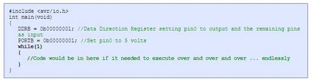
But what exactly all the code means? and what is the structure???
I scratched my head a bit for a while but after reading and listening both tutorials I understood the structure of the code, plus I found a very well documented week from a previous student where he also explains in depth about C programming, Sreejith Mohanan.
Even though it is a simple task to turn on an LED, for me was a new world, here are some of my notes that helped me to understand what was going on:
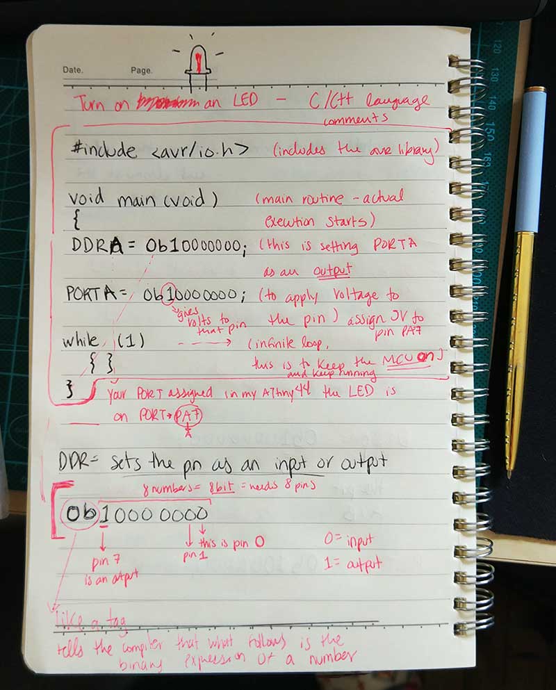
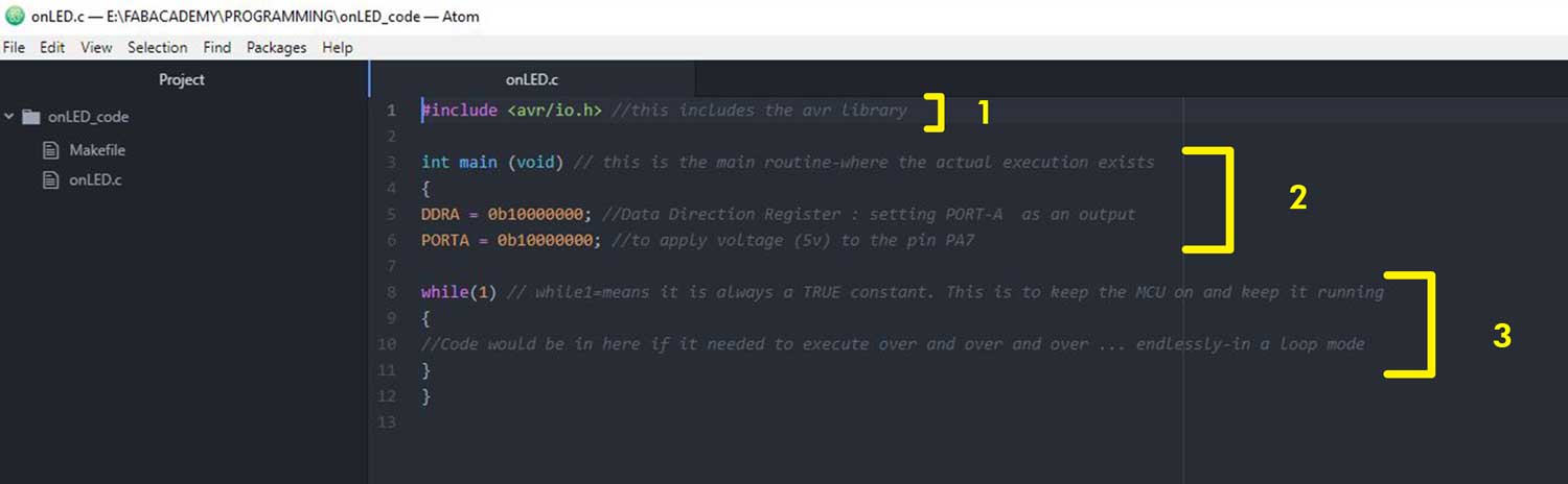
In this case the code has 3 parts:
PART1_here you include the libraries, avr/io.h includes the necessary codes and
definitions for the Atmel AVR microcontrollers. (source from: newbiehack)
PART2_This is the main routine, where the execution starts. In this example, here is wheren you
specify DDR and PORT*
PART3_ This part is to keep running the micro controller, in this code we have no loop but here
is where you would run an infinite loop. Number 1=TRUE.
*DDRA = this is the Data Direction Register, serves to select the mode for the output . A or B
depends on the port your LED is on, in my case is on pin PA7, therefore I type DDRA.
*PORTA = this statement is to supply the voltage to the pin, in this case pin PA7.
And what is all this number meaning? 0b10000000
In binary 0b00000001 means 0, if you shift the 1 towards the left, you are shifting from 1 to 7 which matches your pins on your board from 1-7.
"There are 8 pins for port B; pins 0 though 7. There are also 8 digits in our line of code. So each digit represents a pin on the port, and we can use the individual digits to specifically refer to any one of the pins in port B." -source from newbiehack.com
If you check on minute 54:23 of this video, you can find a detailed explanation about the binary digits in the code when using C language.
Ok, so once I typed my code inside ATOM using the information above, I jumped into modifying the
Makefile.
I forgot to mention, set up the language to C inside ATOM before you begin coding it.
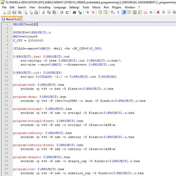
Doing Makefile
Remember that I will be using Neil's example, but there is a part of the code that you should change, and
that is changing the very first line of the code where it says PROJECT=hello.ftdi.44.echo, change
it to the name of your new .C file, in my case I called it onLED.C, so PROJECT=onLED.
Also if you are not using the same ATtiny44 as Neil's example don't forget to change it for your MCU
type.
I copied the code and using NOTEPAD++ I modified the code.
Once it's done save it as Makefile without ANY extension. We do this so that when you run
the task make you can just type make and not the name of the file, so it's better to stick
to Makefile name, keep it simple and easier.
Here are both my onLED.C file and my Makefile:
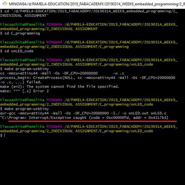
Remember that both files should be inside a folder, once you have ready the files, connect both the FABISP and your MCU and you can run on your terminal (or gitbash) the make command:
make program-usbtiny
If everything went well my LED should turn on and two new files will be generated on the same folder, one .hex file (file for the mcu to understand your .C language programming) and one out file.
Outcomes
I still have the same issue when running MAKE COMMAND in my computer, and I get this error message:
"C:\Program: Interrupt/Exception caught (code = 0xc00000fd, addr = 0x4217b3)"
I tested the code in another computer and it showed an error...
I quickly realized it, as the code is so simple, I went to check what was the issue and I noticed I
typed a different port inside my code, I typed:
DDRA = 0b10000000;
PORTB = 0b10000000;
when it has to be:
DDRA = 0b10000000;
PORTA = 0b10000000;
After solving this small issue, I changed the code and tested it once again in a different computer, and
this time it worked!!!!
My very first C code worked! it is a super simple code to program but I was so happy that I was able to
code it and understand each part of the code.
I didn't upload the video of the result not because of time but because I would like to solve the issue with my MAKE and be able to program it from my computer, and once I do that I will upload the video of the results made from my computer.
_EXTRA NOTES
I am still figuring out how to use Atmel Studio, so hopefully if I have some extra time, I will do some tests using Atmel Studio 7 and will upload the outcomes once I have them.
Also, a friend mentioned me about another IDE called GREAT COW BASIC , I think is similar to Arduino IDE and I would like to give it a try and see how it works.
_DOWNLOAD FILES
Codes used for this assignment:
_BLINK_CLICK_ME (arduino)
_onLED (C code)
_onLED (Makefile)