_stage 3
PCB fabrication
FROM SARDUINO TO CATccess to almost working JOHN TRAVOLTAGE
So far for all the prototyping of my project I've been using my Arduino compatible "SARDUINO" PCB (with
an ATmga328).
I decided I would do two new boards for my project:
_1 One new board based on my SARDUINO that would integrate only the pin outs of the sensors I will use
(leaving aside those I won't be needing from the original SARDUINO)
_2 An external power supply to provide 3.3V & 5V to my sensors.
CATccess board
Having used an arduino compatible board until this point, I decided I would be using an ATmega328 for my
MCU, just as the Satshakit and Sarduino boards.
Before beginning the schematic on Eagle I checked the list of the pins I would be using for this new
PCB:
RFID:
VCC (3.3V)
PB1
GND
MISO
MOSI
SCK
PB2
SERVO MOTOR
PD3 (signal pin, PWM pin)
VCC (5V)
BLUETOOTH
RX (pin PD7)
TX (pin PD6)
VCC (5V)
GND
FTDI (for programing)
GND
VCC
TX
RX
DTR/RST
IR sensor*
VCC (5V)
GND
PC0 (analog pin)
* I wanted to integrate an IR sensor if I had the time, so I decided I would leave the pin out for it on the board and only if I had enough time I would add this sensor.
CATccess board v1
Having a clear understanding of what I needed I started working on my schematic and board.
I have to add that I did a first attempt of a CATccess board that integrated on the same board two
voltage regulators to provide 5V and 3.3V.
From the list of components above I added one
LM3480IM 3.3V 100MA LDO VREG
, and one
LM3480IM 5.0 100MA LDO
VREG.
But this first attempt didn't work out very well... I did a couple of mistakes.
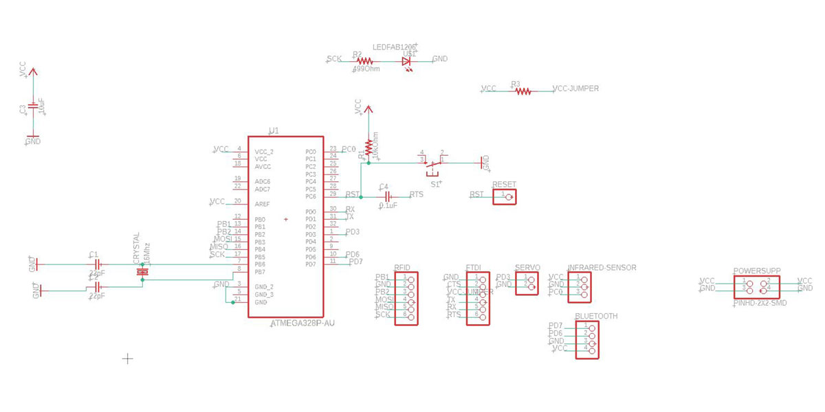
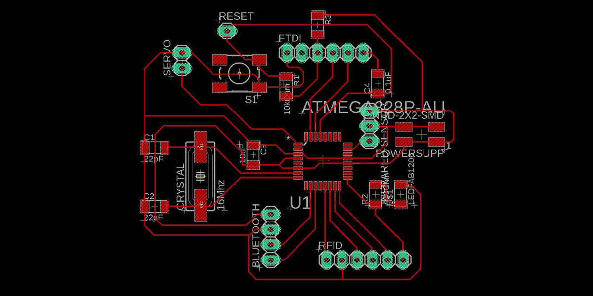
Here are both the schematic and the board designof the first CATccess version I did
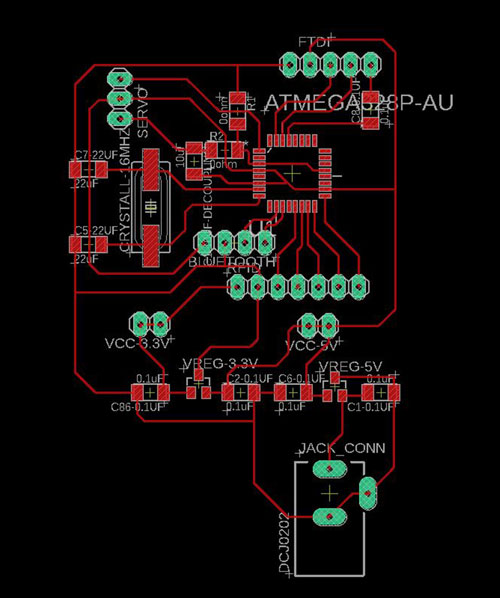
_ERRORS & advices
As you can see from the schematic, I forgot to add the RST pin connected to the 0.1uF
capacitor...
Secondly, when I first powered this module with the FABISP the 5V regulator was extremely hot, I still
haven't figure out the problem, but that was one of the reasons why on the second iteration I decided I
would do two separate boards, one for the "brain" and one for the voltage supply.
This way I could debug the problem of the voltage and keep working in spirals.
When using the barrel connectors "jack" type, make sure you increase the size of the holes on your outlines file, as the default size from Eagle is smaller than the connector and you will struggle i you try to increase the size by hand.
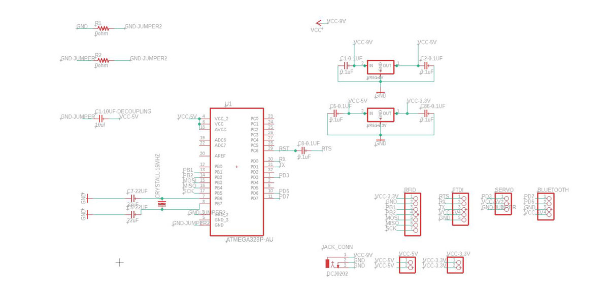
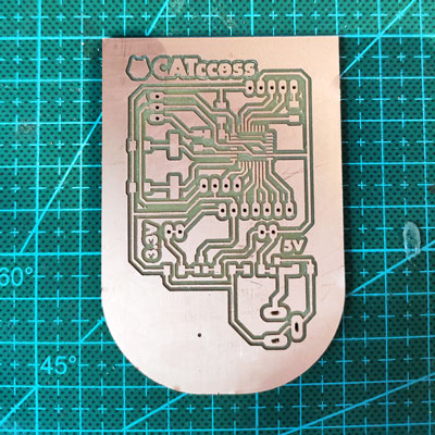
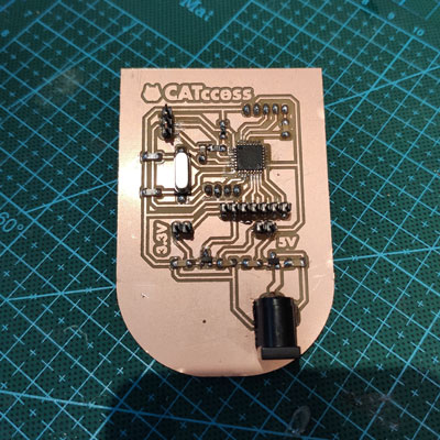
CATccess board v2
So at this point is when I decided to redo the board without the v.reg and modify the previous errors I did.
Among the improvements I did to the new board was adding an LED on pin SCK, so that I could see a light of life when loading codes, otherwise without the LED its hard to now if is breathing the sarduino/catccess.
This board worked well, without issues, I first burn the bootloader to it using the FABISP so that I
could use after the FTDI connection to program it.
So far all went good, the next step was to get done the power supply board and integrate all the
circuits into my structure.
This is a short time lapse that shows the process of soldering the very first CATccess board:
JOHN TRAVOLTAGE

The RFID-RC522 module I am using works with 3.3V only the rest of the sensors work with 5V.
My original idea was to use a 9V battery as my source of supply. This meant I would need to use two types of voltage regulators, one to low the voltage to 5V so I can use it for the servo motor, and the bluetooth module and another v. regulator to low the voltage to 3.3V for the RFID module.
I shared to my instructor what I was planning to do and he suggested to check out a type of battery
called
LiPo battery
that you can easily find of very low voltages such as 3.3V. This would mean I could provide to all
my board the same
voltage directly and to all my sensors, the only drawbacks would be that one: the servo motor works at
5V and the logic level of the bluetooth module works at 5V as well.
The second drawback is that the RFID tag reader the data sheet says that the max voltage you
can give is 3.6V, and I was afraid that the LiPo battery wouldn't give 3.3V precisely and this could
affect the module. So, I abandoned this idea and decided I would do my own power supply board that
supplies 3.3V and 5V from a 9V battery.
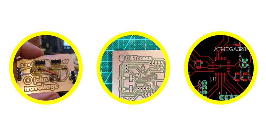
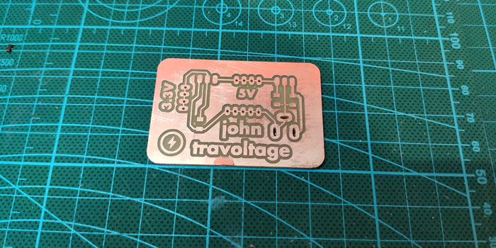
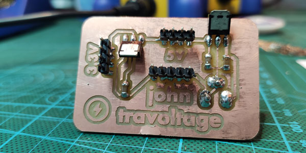
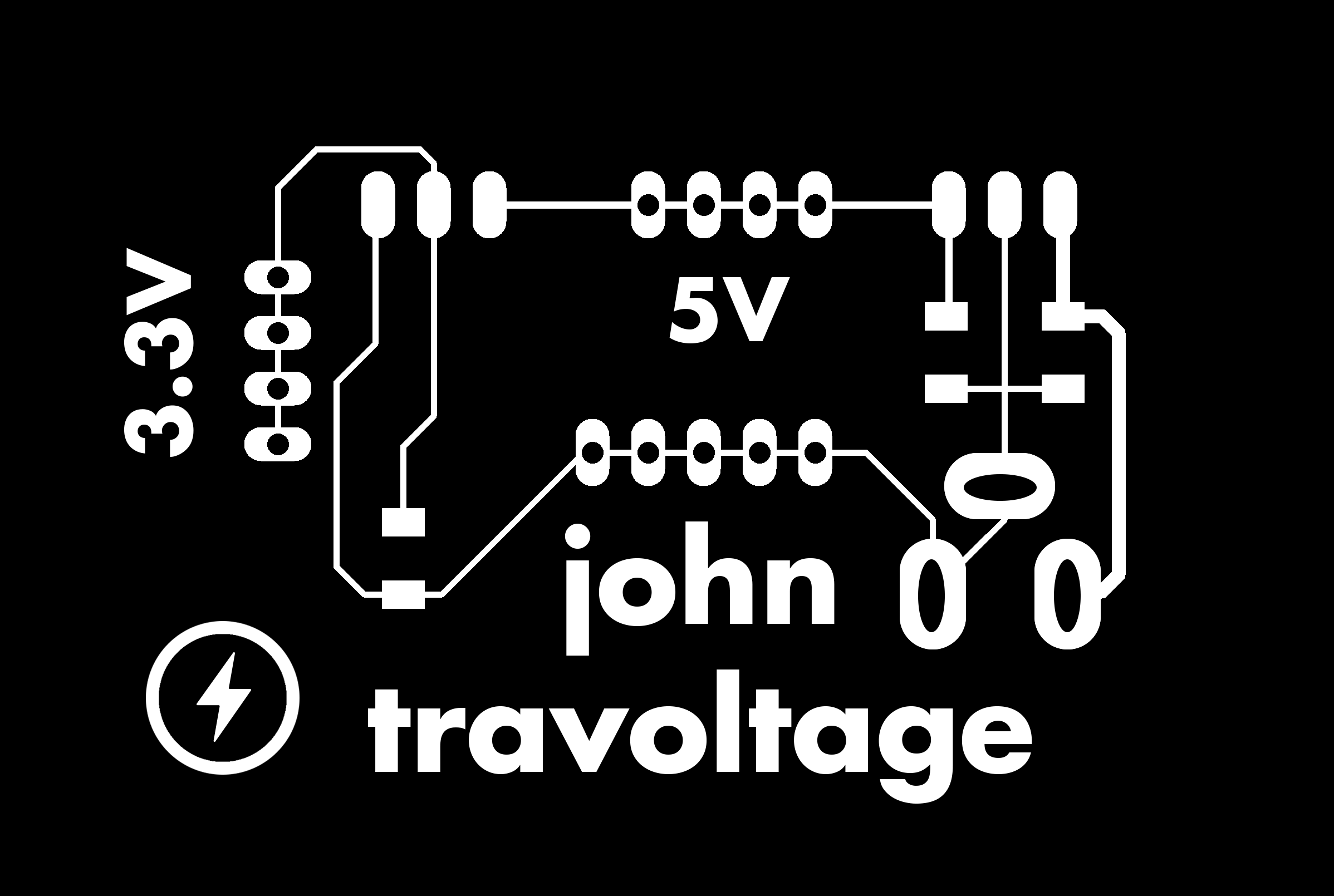
JOHN TRAVOLTAGE n1
For this first iteration I used the following regulators with the capacitors remarked:
_1 Vreg
LM3480IM 3.3V 100MA LDO
with two capacitors 0.1uF
_1 Vreg
LM3480IM 5.0 100MA LDO with
two capacitors 1uF
The barrel connector I soldered it from the bottom up, meaning you have to remember to mirror the component inside Eagle so that the connections match, otherwise you can do a mess with VCC abd GND.
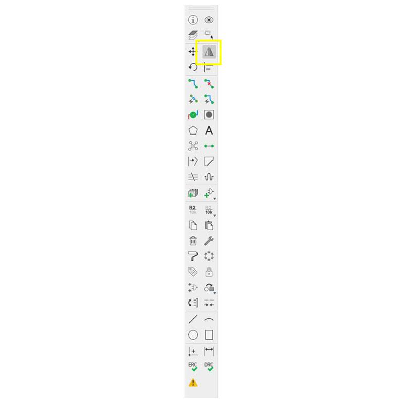
HOW TO MIRROR A COMPONENT ON EAGLE?
Go to brd view, select the component you need to mirror and click the mirror icon:
HOW TO INCREASE THE THICKNESS OF THE TRACES ON EAGLE?
Rico my classmate from Kamakura Lab, gave me the tip.
Inside brd view click on the trace you want to thicken, right click and select PROPERTIES then
set the size inside WIDTH
Here is the schematic and board of the first iteration for my power supply
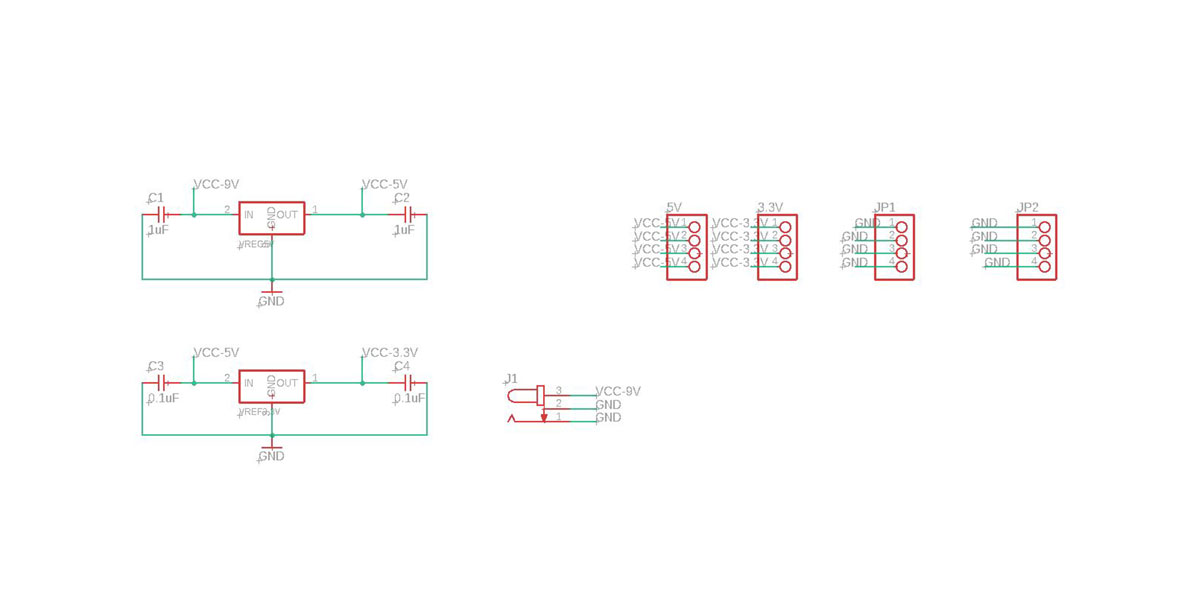
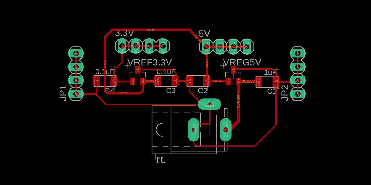
_ERRORS & advices
As you can notice from the schematic, I forgot to add any GND pin headers.
I drilled extra holes and added pin headers for GND. Also a trace fell off and I was missing connection
from the barrel GND to a capacitor and as a consequence the 3.3V reg was missing as well a connection to
GND.
I tried to re-use this board as they always advise us, before making a new one make it look like
Frankenstein, if still something doesn't work then make a new one.
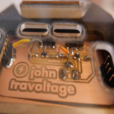
I used the multimeter to check if I was getting the correct voltage, and I got values close to what it was supposed to(around 3.7V and 5.4V), but when I connected the main board (after uploading the code from Arduino) to the power supply together withmy 9V battery, nothing happened it didn't even turn on the LED on mu board
Some of my classmates where having issues with this Vreg as well, so I decided to check other options for
the power supply.
I found out I could use other vreg and as a collague had several of those I decided to redo a new board
using different components.
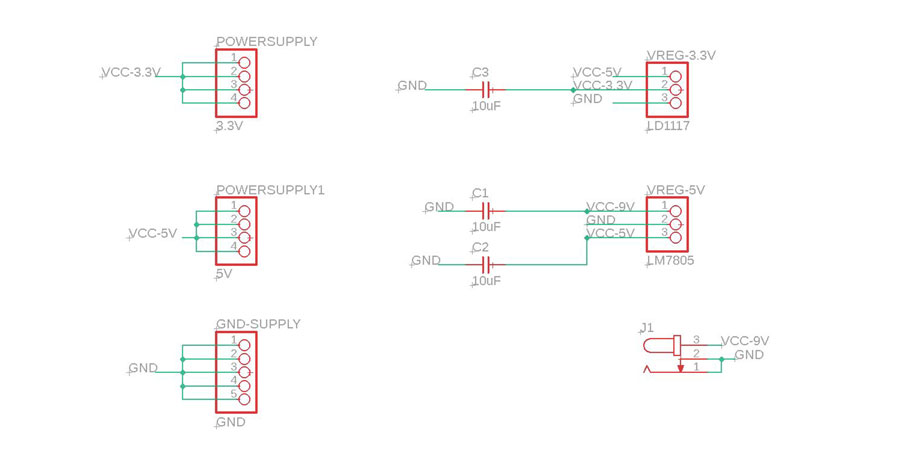
The new Vreg I would be using are:
IC 7805 Voltage
Regulator
, to provide 5V
LD1117 Voltage
Regulator to supply
3.3V.
I found that a previous FabAcademy student had some documentation about these
same Vreg, it served me as a base to create my new PCB (exchange eyes
project
).
I drew some diagrams to understand how the connections work as this components are quite big and the legs
are super tiny, so the best way to solder them is flipping them, meaning you have to be careful when
drawing the board and connecting all the components.
So to make it easier and to avoid confusions I did some diagrams of the connections before working on
the new board.
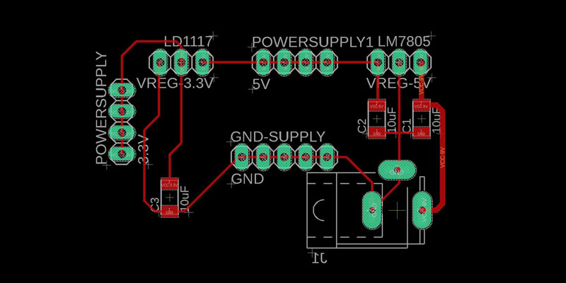
JOHN TRAVOLTAGE n2
So after doing my diagram and understanding the connections I drew a new pcb based on the previous power supply adding the missing GND pin headers and on the new Vreg components and connections from the documentation of the student that I found.
Once finished I connected the main board, the 9V to the power supply and I tried it, and....
not working... At this point I thought (and I still think) working with different voltages can be quite
challenging and delicate.
I was working at the lab and I asked to my peers to have a look to the problem I was facing, and I have
to say proudly that all together the team we solved the mistery, it felt nice because we were alone
without our instructor and we tried to workout the problem as Saverio would have suggested us.
We decided to connect the board to the power supply bench machine we have at the lab giving it the same
power and current as the battery was giving and then we increased the current to 2 amperes.
When we gave 9V and more than 2 amperes the board worked perfectly, seems like the 9V battery has lower
current and the board needs more current to work with.
So at this point the best solution was to use an AC/DC power adaptor of 9V/2Amperes (with jack barrel type connection) to supply power to my board and make it stand-alone the hole system.
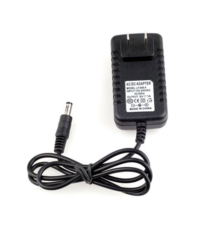
I did tests at the lab using this type of adaptor and the system worked, a couple of days after when I
had to present and prepare the whole system I noticed that every time I connected everything with the
adaptor the system would work reading the tag once and then nothing else would happen, the LED on the
board appears to be on but the servo motor doesn't go back to close position. On the other hand, if I
use the FTDI to supply 5V from my computer directly to the main CATccess board without passing through
the voltage gulators it works fine all the system.
So, I am wondering if the voltage regulator is not working properly or the Ampers are still not enough,
this is an issue I still need to solve and improve on my project.
_IMPROVEMENTS
1_Solve the problem with the voltage regulator and understand why the 9V power adaptor is not working
properly.
TASKS COMPLETED
_PCB FABRICATION ✔
_DOWNLOAD FILES
_CATcess v1 schematic
_CATcess v1 board
_CATcess v2
schematic
_CATcess v2
board
_JOHN TRAVOLTAGE V1
schematic
_JOHN TRAVOLTAGE V1
board
_JOHN TRAVOLTAGE V2
schematic
_JOHN TRAVOLTAGE V2
board
_JOHN TRAVOLTAGE
V2 TRACES
_JOHN TRAVOLTAGE
V2 OUTLINES